JP2013504468A - Radome and apparatus for attaching the radome to an aircraft - Google Patents
Radome and apparatus for attaching the radome to an aircraft Download PDFInfo
- Publication number
- JP2013504468A JP2013504468A JP2012528435A JP2012528435A JP2013504468A JP 2013504468 A JP2013504468 A JP 2013504468A JP 2012528435 A JP2012528435 A JP 2012528435A JP 2012528435 A JP2012528435 A JP 2012528435A JP 2013504468 A JP2013504468 A JP 2013504468A
- Authority
- JP
- Japan
- Prior art keywords
- radome
- locking
- airframe
- aircraft
- centering
- Prior art date
- Legal status (The legal status is an assumption and is not a legal conclusion. Google has not performed a legal analysis and makes no representation as to the accuracy of the status listed.)
- Pending
Links
Images


Classifications
-
- H—ELECTRICITY
- H01—ELECTRIC ELEMENTS
- H01Q—ANTENNAS, i.e. RADIO AERIALS
- H01Q1/00—Details of, or arrangements associated with, antennas
- H01Q1/42—Housings not intimately mechanically associated with radiating elements, e.g. radome
-
- B—PERFORMING OPERATIONS; TRANSPORTING
- B64—AIRCRAFT; AVIATION; COSMONAUTICS
- B64C—AEROPLANES; HELICOPTERS
- B64C1/00—Fuselages; Constructional features common to fuselages, wings, stabilising surfaces or the like
- B64C1/36—Fuselages; Constructional features common to fuselages, wings, stabilising surfaces or the like adapted to receive antennas or radomes
-
- H—ELECTRICITY
- H01—ELECTRIC ELEMENTS
- H01Q—ANTENNAS, i.e. RADIO AERIALS
- H01Q1/00—Details of, or arrangements associated with, antennas
- H01Q1/27—Adaptation for use in or on movable bodies
- H01Q1/28—Adaptation for use in or on aircraft, missiles, satellites, or balloons
- H01Q1/281—Nose antennas
-
- Y—GENERAL TAGGING OF NEW TECHNOLOGICAL DEVELOPMENTS; GENERAL TAGGING OF CROSS-SECTIONAL TECHNOLOGIES SPANNING OVER SEVERAL SECTIONS OF THE IPC; TECHNICAL SUBJECTS COVERED BY FORMER USPC CROSS-REFERENCE ART COLLECTIONS [XRACs] AND DIGESTS
- Y10—TECHNICAL SUBJECTS COVERED BY FORMER USPC
- Y10T—TECHNICAL SUBJECTS COVERED BY FORMER US CLASSIFICATION
- Y10T29/00—Metal working
- Y10T29/49—Method of mechanical manufacture
- Y10T29/49002—Electrical device making
- Y10T29/49016—Antenna or wave energy "plumbing" making
Abstract
【課題】本発明は、航空機用レドーム(1)に関し、より具体的には前記レドームを前記航空機の構造体に接続するための装置に関する。
【解決手段】本発明の主題であるレドームは、航空機の機体(10)とレドーム(1)の対向する面同士を接合可能な複数のロッキングユニットを含み、前記ユニットの各々が、
−取付手段を介して、前記機体の表面に対して略垂直方向に、前記表面に牽引力を発揮可能なロッキング手段(20)と、
−前記機体及びレドームの対向する面に対して略接線方向のせん断力に耐えることが出来るセンタリング手段とを含み、
−前記ロッキング手段(20)は、前記レドーム(1)内のアセンブリによって発生する曲げ応力を最小にするように前記センタリング手段にかかる合力の円錐内に位置するように配置される。
【選択図】図1The present invention relates to an aircraft radome (1), and more particularly to an apparatus for connecting the radome to a structure of the aircraft.
A radome, which is the subject of the present invention, includes a plurality of locking units capable of joining opposing surfaces of an aircraft fuselage (10) and a radome (1), each of the units comprising:
A locking means (20) capable of exerting a traction force on the surface in a direction substantially perpendicular to the surface of the airframe via an attachment means;
-Centering means capable of withstanding substantially tangential shear forces against the opposing surfaces of the fuselage and radome;
The locking means (20) is arranged to lie within a cone of resultant forces on the centering means so as to minimize bending stresses caused by the assembly in the radome (1).
[Selection] Figure 1
Description
本発明は、航空機用レドームに関し、より具体的にはレドームを航空機の構造体に接続するための装置に関する。 The present invention relates to aircraft radomes, and more particularly to an apparatus for connecting a radome to an aircraft structure.
ほとんどの航空機、より具体的には民間航空輸送機は、機体のノーズコーンに位置するレドームを含む。空気力学的役割に加えて、このレドームはレーダを保護する。結果的に、レドームは電磁波を通すことが出来る材料、一般的には複合材料からなる。レドームのこれらの機能のために、レドームの設計及び製造にはいくつかの制約が課される。即ち、
−レドームの下側に位置するレーダへのアクセスを可能にするために、レドームが、取り外し可能なものでなくてはならず、容易に取り外し又は取り付け(retract)可能なものであると有利であること、
−レドームにはレーダを保護するという役割があり、特にあらゆる衝撃にさらされる領域に位置するため、レドームは、特に耐久性がなくてはならず、また、機体への接続同然に、気密性がなくてはならないこと、
−レドームが機体と完全には水平でないがために気流に乱気流が発生するのを回避するために、レドームがノーズコーンにおいて空気力学的に位置するように、機体の形状に完全に調和しなければならないということが課される。
Most aircraft, and more specifically civil air transport aircraft, include a radome located at the nose cone of the fuselage. In addition to the aerodynamic role, this radome protects the radar. As a result, the radome is made of a material that can transmit electromagnetic waves, generally a composite material. Because of these functions of the radome, some constraints are imposed on the design and manufacture of the radome. That is,
-In order to allow access to the radar located below the radome, the radome must be removable and it is advantageous if it can be easily removed or retracted. about,
-The radome has a role in protecting the radar, especially in the area exposed to all impacts, so the radome must be particularly durable and, as well as connected to the fuselage, it is airtight. What you have to do,
-In order to avoid turbulence in the airflow because the radome is not completely horizontal to the aircraft, it must be perfectly matched to the shape of the aircraft so that the radome is located aerodynamically in the nose cone. It is imperative not to be.
これらの要件は色々な意味で相矛盾する。例えば、透磁率のためには複合材料で製造することが有利である。しかし、耐衝撃性という制約事項にふさわしい耐荷重層(plies)の形状及び定義の複雑さによって、硬化後のアセンブリが複雑に変形したり、レドームの形状を機体の形状に適応させることが困難になったりする。この適応は、二重曲率形状や高剛性部品が存在する場合には更に複雑である。 These requirements contradict each other in many ways. For example, it is advantageous to manufacture with a composite material for magnetic permeability. However, the complexity of the shape and definition of the load-bearing layer (plees) that meets the constraints of impact resistance makes it difficult for the cured assembly to deform complexly and to adapt the shape of the radome to the shape of the aircraft. Or This adaptation is more complicated when there are double curvature shapes and high rigidity parts.
先行技術によれば、基本的に、これらの様々な要件を折衷する2つの方法が用いられる。1つ目の方法は、機体との接合部分におけるレドーム内に剛性金属フレームを組み込み、前記フレームの形状を高精度に製造し、機体側の接合部分の形状に適応させる。この構成はその製造精度のためにコストがかかり、また金属部品が存在するため質量に関し悪影響を及ぼす。しかし、この周縁領域の剛性によって、開放機構を設置することが出来るようになり、その開放機構の運動学によって、レドームを取り外すことなくレーダに迅速にアクセスすることが容易になる。 According to the prior art, basically two methods are used to compromise these various requirements. In the first method, a rigid metal frame is incorporated in the radome at the joint portion with the airframe, the shape of the frame is manufactured with high accuracy, and the shape is adapted to the shape of the joint portion on the airframe side. This configuration is costly due to its manufacturing accuracy and has a negative effect on mass due to the presence of metal parts. However, the rigidity of this peripheral region allows an opening mechanism to be installed, and the kinematics of the opening mechanism facilitates quick access to the radar without removing the radome.
別の方法は、本出願人名義の特許文献1に記述されているが、剛性部品を含まないフレキシブルなアセンブリ接合部分を製造し、その円周上に複数の固締具を配置することによって機体に接続する。この構成から、接合部分の柔軟性により、複数の固定具を用いた機体の形状に順応させるという利点が得られる。一方、1つ目の方法と比較して、レドームを開閉する都度、複数の固締具を外したり締めたりしなくてはならないため、レドームを取り外す及び/又は開放するためにより長い時間を要する。これらの固締具は、特にレドームと機体端部との間の接合部分におけるレドームの柔軟性を補償するために多数配置される。
Another method is described in
本発明は、質量の点で不利益をもたらすことなく迅速に開放又は取り外し可能である点を維持しつつ、機体に適合し且つ水平になるよう向上させた嵌着/開放装置と連携する構成を有するレドームを提案することによって、先行技術の欠点を改善することを目的とする。 The invention works in conjunction with an improved fit / release device that is adapted to the aircraft and leveled while maintaining the point that it can be quickly opened or removed without causing any penalty in terms of mass. The aim is to remedy the disadvantages of the prior art by proposing a radome with.
この目的を達成するため、本発明は航空機用レドームを提案し、このレドームは、航空機の機体とレドームの対向する面同士を接合可能な複数のロッキングユニットを含み、前記ユニットの各々が、
−取付手段を介して、前記機体の表面に対して略垂直方向に、前記表面に対して牽引力を発揮可能なロッキング手段と、
−前記機体とレドームの対向する面に対して略接線方向のせん断力に耐えることが出来るセンタリング手段とを含み、
−前記ロッキング手段は、前記レドーム内のアセンブリによって発生する曲げ応力を最小にするように前記センタリング手段にかかる合力の円錐内に位置するように配置される。
In order to achieve this object, the present invention proposes an aircraft radome, which includes a plurality of locking units capable of joining the aircraft body and the opposing surfaces of the radome, each of the units comprising:
A locking means capable of exerting a traction force on the surface in a direction substantially perpendicular to the surface of the airframe via an attachment means;
-Centering means capable of withstanding substantially tangential shear forces with respect to the airframe and the opposing surface of the radome;
The locking means are arranged to lie within a cone of resultant force on the centering means so as to minimize bending stresses caused by the assembly in the radome.
このように、前記レドームにおいて、特に、レドームと機体との接合部分で曲げ応力を最小にすることによって、レドームが前記機体の形状に対して完全に水平になるように順応する柔軟性を有することが出来、レドームを嵌着/取り外しするために多大な時間がかからないようにロッキングユニットの数を減少することが出来る。 Thus, the radome has the flexibility to adapt the radome to be completely horizontal to the shape of the airframe, especially by minimizing bending stress at the joint between the radome and the airframe. The number of locking units can be reduced so that it does not take much time to insert / remove the radome.
本発明は、以下に記述する複数の有利な実施形態に従って実施可能であり、これらの実施形態は単独でも技術的に効果的な任意の組み合わせにおいてでも考慮することができる。 The invention can be implemented in accordance with several advantageous embodiments described below, which can be considered alone or in any technically effective combination.
本発明の主題であるレドームは、レドームの構造体に、機体と接合する端部から延びる長手方向スロットを含むと有利である。 The radome, the subject of the present invention, advantageously includes a longitudinal slot in the radome structure that extends from the end that joins the fuselage.
このようにして、前記接合部分の柔軟性を増加させることが出来る。 In this way, the flexibility of the joint portion can be increased.
特に有利な実施形態によれば、レドームは、レドームの構造体に、機体との接合部分の端部から延び、前記端部の円周上に配置された複数の縦方向スロットを含み、前記複数のロッキングユニットの各々が、レドームに固定されスロットの両縁部にわたる剛性支持面を含む。 According to a particularly advantageous embodiment, the radome includes a plurality of longitudinal slots in the radome structure extending from the end of the joint with the fuselage and arranged on the circumference of the end. Each of the locking units includes a rigid support surface secured to the radome and extending across the edges of the slot.
このように、これらのスロットの存在によって、機体との接合部分を形成する前記レドームの端部における形状及び周長の両方に適応性をもたらすことができ、これにより、前記レドームの前記接合部分の端部において、2つの構造体を完全に水平に且つ適応させるが出来る。 Thus, the presence of these slots can provide flexibility in both the shape and circumference at the end of the radome that forms the junction with the fuselage, thereby allowing the joint portion of the radome to be adapted. At the end, the two structures can be perfectly horizontal and adapted.
スロットの数は、機体と接合する端部の形状、性質、及び剛性に従って、この端部の形状及び周長の両方において適応可能な力量次第で決定される。実際には、スロットの数は、必要に応じて試作品試験を含めた数値シミュレーションによって確定される。 The number of slots is determined by the amount of force that can be accommodated in both the shape and circumference of this end, according to the shape, nature, and stiffness of the end joining the fuselage. In practice, the number of slots is determined by numerical simulation including prototype testing as needed.
スロットの両縁部にわたる一面を有するロッキングユニットはブラケットとして機能し、接合部分の構造的連続性を確保することが出来、且つ、一旦接合部分を適合すると、力の流れがスロットを通過せずに消散させることを可能にする。この構造的役割をロッキング機能と組み合わせることで、スロットの存在下で特定の荷重支持ブラケットによって追加される質量を制限することができる。 A locking unit with one side across the edges of the slot can act as a bracket, ensuring structural continuity of the joint, and once the joint is fitted, force flow does not pass through the slot Makes it possible to dissipate. This structural role can be combined with a locking function to limit the mass added by a particular load bearing bracket in the presence of a slot.
本発明の主題である前記レドームは、有利に、前記機体と接合する端部から、各ロッキングユニットの下に及ぶモノリシックな周縁領域を含み、レドームのその他の部分はハニカム構造体から形成される。このモノリシック領域は、構造体の残りの部分と共硬化(co−cured)すると有利であり、その結果、レドームの端部に剛性をもたらし、従って限られた数のアンカーポイント、及び開放又は閉鎖(retraction)のための単純化したオプション、特にヒンジによって、レドームを適切な位置に保持することが出来るようになる。先行技術とは異なり、この剛性周縁領域は、特別精密に製造されるものではなく、複数のスロットによって機体に適応可能であり、これによって、前記レドームは経済的に製造することが可能になる。 The radome, which is the subject of the present invention, advantageously comprises a monolithic peripheral region extending from the end joining the fuselage and under each locking unit, the other part of the radome being formed from a honeycomb structure. This monolithic region is advantageously co-cured with the rest of the structure, resulting in rigidity at the end of the radome and thus a limited number of anchor points and open or closed ( A simplified option for retraction), in particular a hinge, allows the radome to be held in place. Unlike the prior art, this rigid peripheral region is not specially manufactured, but can be adapted to the fuselage by means of a plurality of slots, which allows the radome to be manufactured economically.
この剛性周縁領域を有利に使用し、特にこの周縁領域に溝を形成し、機体に固定された変形可能なシールの端部を収容することによって、レドームを確実に気密封止することが出来る。この封止機能を実行する手段をレドームの壁の厚みに組み込むことによって、複数のロッキング手段を壁に対して半径方向により近接させ、これにより、これらのロッキング手段上の力の作用点とこれらのロッキング手段が固定されるレドームの壁との距離によって引き起こされる寄生的な(parasite)曲げ及びせん断効果を制限することが出来るようになる。 This rigid peripheral region can be used advantageously, in particular by forming a groove in this peripheral region and accommodating the end of a deformable seal fixed to the fuselage, so that the radome can be reliably hermetically sealed. By incorporating the means for performing this sealing function into the wall thickness of the radome, the plurality of locking means are brought closer to the wall in the radial direction, so that the point of action of the forces on these locking means and these It becomes possible to limit the parasitic bending and shearing effects caused by the distance from the wall of the radome to which the locking means is fixed.
センタリング手段は、レドームを閉じたとき機体側の複数のリセプタクルに嵌着する複数のセンタリングデバイスによって構成されると有利である。レドームの位置決めを容易に繰り返すことができるという利点に加え、レドームが開閉される都度、これらのセンタリング装置は、接合部分の平面に略平行なせん断力に耐える。 The centering means is advantageously constituted by a plurality of centering devices that fit into a plurality of receptacles on the airframe side when the radome is closed. In addition to the advantage that the radome positioning can be easily repeated, each time the radome is opened and closed, these centering devices withstand shear forces that are substantially parallel to the plane of the joint.
このように、ロックには位置決め機能を果たす役割はないため、ロックは、特に牽引フックロックなどの先行技術で既知の「すぐに取り外し可能な」タイプのロックから選択可能であり、レドームの外面に対して同一平面にあるレバーの一回の操作でロック又はアンロック(ロック解除)することが可能になる。従って、レドームの外側から上記ロックをアンロックすることが出来るので、業務時間を短縮させてレーダにアクセスすることが容易になる。このタイプのロックは、ロッキング軸に対して高い抵抗を示すが、この軸に対して垂直な抵抗は低減するので、低減した抵抗は複数のセンタリングデバイスの存在によって補償される。 In this way, since the lock has no role to perform the positioning function, the lock can be selected from “ready to remove” type locks known in the prior art, such as tow hook locks in particular, on the outer surface of the radome. On the other hand, it is possible to lock or unlock (unlock) by one operation of a lever on the same plane. Therefore, since the lock can be unlocked from the outside of the radome, it becomes easy to access the radar while reducing the work time. This type of lock exhibits a high resistance to the locking axis, but since the resistance perpendicular to this axis is reduced, the reduced resistance is compensated by the presence of multiple centering devices.
複数のロッキングユニットは、複数のセンタリング装置を支持するように使用すると有利であり、これによって、部品数を制限でき、質量の点で利益を得られ、とりわけ、複数のセンタリング装置を複数のロッキング装置の取付けポイントにより近接させることが可能になるため、前記ロッキング装置を容易に支持することができ、結果的にロッキングを安全にすることが可能になる。 A plurality of locking units can be advantageously used to support a plurality of centering devices, which can limit the number of parts and benefit in terms of mass, in particular, a plurality of centering devices can be used with a plurality of locking devices. The locking device can be easily supported, and as a result, the locking can be made safe.
少なくとも2つのロッキングユニットが、機体に対してレドームを予め位置決めするための装置を含み、この装置がエラストマー製ワッシャに嵌着するピンによって構成されると有利である。これらの装置によって前記レドームの嵌着がより容易になる。エラストマーワッシャによって、レドームが機体上に複数のセンタリング装置によって位置決めされてしっかりと固定される前に、機体に対する前記レドームの相対的な配置及び保持が確実に行われる。この事前位置決め装置を前記複数のロッキングユニットに組み込むことによって、機体上に設置されるブラケットの数を制限し、質量を減少させることが可能になる。複数のユニットは、複数の事前位置決めピン又はエラストマーワッシャのいずれかを収容することが出来、この構成はユニットごとに変更可能である。レドームの寸法又は重量に対してこの構成が必要となる場合、このタイプの事前位置決めピンは4つ使用される。 Advantageously, the at least two locking units comprise a device for pre-positioning the radome relative to the fuselage, which device is constituted by a pin that fits into an elastomer washer. These devices make it easier to fit the radome. Elastomeric washers ensure that the radome is positioned and retained relative to the fuselage before the radome is positioned and secured by the plurality of centering devices on the fuselage. By incorporating this pre-positioning device into the plurality of locking units, it is possible to limit the number of brackets installed on the airframe and reduce the mass. The plurality of units can accommodate either a plurality of pre-positioning pins or elastomer washers, and this configuration can vary from unit to unit. If this configuration is required for the radome size or weight, four pre-positioning pins of this type are used.
少なくとも2つのピンが、接合部分の平面に略平行な軸に沿ってレドームを連結するように設計された形状を有すると有利である。レドームが位置決めピンを2つのみ含む場合、これらのピンはこのタイプのピンであると好ましい。従って、これらのピンは、レドームを取り外すことなく迅速に開放するためのヒンジとして機能する。本発明に従うレドームが軽量であるため、前記のように連結させるためのブラケット及びフレームを設置することなく、複数のエラストマーワッシャによってこのような連結が実現可能になる。複数のピンが前記複数の剛性のユニットに接続され、複数の剛性のユニットも同様に剛性のモノリシック周縁領域に固定されているので、これら2か所の取付けポイントより、レドームが自重によって損傷する危険がなく、レドームを開放位置に十分に維持できる。 Advantageously, the at least two pins have a shape designed to connect the radomes along an axis substantially parallel to the plane of the joint. If the radome includes only two locating pins, these pins are preferably this type of pin. Thus, these pins function as hinges for quick opening without removing the radome. Since the radome according to the present invention is lightweight, such a connection can be realized by a plurality of elastomer washers without installing a bracket and a frame for connection as described above. Multiple pins are connected to the rigid units, and the rigid units are similarly fixed to the rigid monolithic peripheral area, so the risk of damage to the radome due to its own weight from these two attachment points The radome can be sufficiently maintained in the open position.
本発明は、上述した複数の実施形態のいずれかに対応するレドームを含む航空機にも関連する。 The present invention also relates to an aircraft including a radome corresponding to any of the embodiments described above.
図1乃至図11に示す本発明の好適で非制限的な複数の実施形態に即して、本発明を以下により正確に記述する。 In accordance with the preferred and non-limiting embodiments of the present invention shown in FIGS. 1-11, the present invention will be described more precisely below.
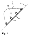
図1及び図2において、本発明に従うレドーム(1)は、電磁波を通す材料、好ましくはハニカムタイプの複合材料から作られた二重曲率面(12)を含む。航空機の機体に固定される接合部分端(10)から、前記レドームは、複数のロッキング装置(20)の位置まで及ぶ剛性モノリシックリング(11)を含む。この剛性モノリシックリングは、特にレドームが開放している間、例えば、レドームの下側に配置されたレーダの検査又はメンテナンス作業の間、レドームの形状を維持する。 1 and 2, the radome (1) according to the present invention comprises a double curvature surface (12) made of a material that transmits electromagnetic waves, preferably a honeycomb type composite material. From the joint end (10) secured to the aircraft fuselage, the radome includes a rigid monolithic ring (11) that extends to the location of a plurality of locking devices (20). This rigid monolithic ring maintains the shape of the radome, especially while the radome is open, for example during inspection or maintenance work of the radar placed under the radome.
また、このリング(11)の剛性により、より少ない数の機体アンカリング及びロッキングポイントでレドームを機体に対して固定した状態で維持することが出来る。一方、前記リングの剛性のために、接合部分端(10)の形状を機体の形状に対して完全に水平に且つ適応させることが出来ない。レドームの接合部分のリングの形状及び周長を航空機の機体に適応可能にするため、レドームの構造体に複数のスロット(100)を形成し、これらのスロット(100)は、接合部分端(10)から、モノリシックリング(11)内へと続き、モノリシックリング(11)の端を越えて延びている。前記複数のスロット(100)は、このアセンブリの接合部分に対して略垂直であり、従ってこれらのスロットによってレドームの形状及び周長を適応させることが出来る。 Further, the rigidity of the ring (11) allows the radome to be maintained in a fixed state with respect to the airframe with a smaller number of airframe anchoring and locking points. On the other hand, due to the rigidity of the ring, the shape of the joint end (10) cannot be adapted to be completely horizontal and adaptable to the shape of the airframe. In order to adapt the ring shape and circumference of the radome joint to the aircraft fuselage, a plurality of slots (100) are formed in the radome structure, and these slots (100) are joined to the joint end (10 To the monolithic ring (11) and extends beyond the end of the monolithic ring (11). The plurality of slots (100) are generally perpendicular to the interface of the assembly, so that the shape and circumference of the radome can be accommodated by these slots.
図3において、スロット(100)は、2つの部分からなる。その内の第1の部分(200)は、略矩形であって、ロック(20)、好ましくはトグルファスナを有するクランプ型ロックを収容可能であるが、この部分(200)は、接合部分端から、適切なロッキング装置を収容するのに十分な長さに渡って延出する。このノッチ(200)を延長して狭スロット(100)が形成される。 In FIG. 3, the slot (100) consists of two parts. The first portion (200) therein is generally rectangular and can accommodate a lock (20), preferably a clamp-type lock having a toggle fastener, which portion (200) extends from the end of the joint portion. Extending over a length sufficient to accommodate a suitable locking device. This notch (200) is extended to form a narrow slot (100).
レドームを搭載予定の航空機上又はテンプレート上で直接機体に対してレドームをレドームの形状及び周長を適応させることが出来る。雌型のテンプレートを使用することが出来ると有利であり、この雌型のテンプレートに対してレドーム(1)の外面がモノリシックリング(11)のレベルでプレスされる。複数のスロットによって、テンプレートの全周囲に沿ってリングをテンプレート上に着座させるように制御することによる較正を行うのに十分な柔軟性がもたらされる。較正後、複数のロッキングユニット(30)が、図3及び図4に示すように、複数のスロットに沿ってレドームの内面上に固定される。 The shape and circumference of the radome can be adapted to the airframe directly on the aircraft or template on which the radome is to be mounted. Advantageously, a female template can be used, against which the outer surface of the radome (1) is pressed at the level of the monolithic ring (11). The multiple slots provide sufficient flexibility to calibrate by controlling the ring to sit on the template along the entire perimeter of the template. After calibration, a plurality of locking units (30) are secured on the inner surface of the radome along the plurality of slots, as shown in FIGS.
図4において、ロッキングユニットは、ロック配置ノッチ(200)及びスロット(100)にわたるぐらい十分に幅広の基部(31)を備える。ユニットは、一旦固定されると、リング(11)を環状方向に剛性化し、複数のスロット及びノッチによって得られた柔軟性を解消する。その結果、レドームはテンプレートの形状を保持する。 In FIG. 4, the locking unit comprises a base (31) that is wide enough to span the lock placement notch (200) and the slot (100). Once fixed, the unit stiffens the ring (11) in an annular direction, eliminating the flexibility gained by the multiple slots and notches. As a result, the radome retains the shape of the template.
次に、レドームはテンプレートから取り出され、複数のロック(20)が夫々の位置に設置される。接着及び樹脂性ウェッジ(22)が、ノッチ(200)を閉塞するように各ロックの前方に配置され、スロット(100)は、短繊維を含むポリスルフィド系マスチック又はエポキシ樹脂によって閉塞される。 The radome is then removed from the template and a plurality of locks (20) are installed at each position. An adhesive and resinous wedge (22) is placed in front of each lock to occlude the notch (200), and the slot (100) is occluded by a polysulfide-based mastic or epoxy resin containing short fibers.
ロッキングユニットの基部(31)がスロット(100、200)にわたるので、一旦ユニットがレドーム上に固定されると、円周方向及び縦方向の力の流れが、スロット(200、100)に圧力を加えることなく複数のユニットを通過する。ユニット(30)は、これらの力の流れに抵抗するように設計される。この荷重伝達を促進するために、レドームの接合部分端にあるモノリシック部分(11)は、ロッキングユニットの基部(31)の下に延出することが好ましい。各ロッキングユニットに関して、レドーム上への基部の着座は、ユニットの基部とレドーム上のユニット支持表面との間に樹脂を介在させることによる補償較正によって調整される。 Since the base (31) of the locking unit spans the slot (100, 200), once the unit is secured on the radome, the circumferential and longitudinal force flow applies pressure to the slot (200, 100). Pass through multiple units without. The unit (30) is designed to resist these force flows. In order to facilitate this load transmission, the monolithic portion (11) at the end of the joint portion of the radome preferably extends below the base (31) of the locking unit. For each locking unit, the seating of the base on the radome is adjusted by compensation calibration by interposing a resin between the base of the unit and the unit support surface on the radome.
ロッキングユニットは、7000系から選択された高性能アルミニウム合金から作られ、且つ機械加工によって得られると有利である。この実例によれば、ロッキングユニットは、500×300×300mm3の体積を占める略プリズム状中空要素の形状を有する。ユニットの壁の典型的な厚みは、1.5mm〜2.5mmである。このようなユニットの環状剛性は、レドームの構造的完全性に一部貢献し、航空機の構造体に対するアンカーポイントを補強し、従って、これらのアンカーポイントの数を減少することが可能になる。典型的には、このタイプのアンカー個所の数は、接合部分端の直径が2メートルの広胴型航空機の前記レドームでは8つにまで減少出来る。 The locking unit is advantageously made from a high performance aluminum alloy selected from the 7000 series and obtained by machining. According to this example, the locking unit has the shape of a substantially prismatic hollow element occupying a volume of 500 × 300 × 300 mm 3 . The typical thickness of the unit wall is 1.5 mm to 2.5 mm. The annular stiffness of such a unit contributes in part to the structural integrity of the radome and can reinforce anchor points for the aircraft structure and thus reduce the number of these anchor points. Typically, the number of anchors of this type can be reduced to eight for the radome of a wide-body aircraft with a joint end diameter of 2 meters.
図4において、ユニットの剛性を利用して、航空機構造体上でレドームをセンタリングしてロッキングするための全ての機能をこれらの要素に集合させると有利である。 In FIG. 4, it is advantageous to take advantage of the unit's stiffness to aggregate these elements with all the functions for centering and locking the radome on the aircraft structure.
有利な一実施形態によれば、レドームは、複数の球状センタリング装置(40)及び複数のラッチフック(21)によって航空機に接続される。好ましくは、これらは両方とも複数のリセプタクルブラケット(50)を用いて航空機構造体に接続され、各リセプタクルブラケットは、対向するロッキングユニットのセンタリング球体(40)を収容するように設計されたγ/2の円錐角を有する円錐状リセプタクル(510)と、フック(51)用接続ブラケットを収容する線条領域(520)とを含む。リセプタクルブラケット(50)は、例えば、チタンT40から作られ、同様にチタン製の複数のねじによって航空機構造体に固定される。 According to an advantageous embodiment, the radome is connected to the aircraft by means of a plurality of spherical centering devices (40) and a plurality of latch hooks (21). Preferably they are both connected to the aircraft structure using a plurality of receptacle brackets (50), each receptacle bracket designed to accommodate the centering sphere (40) of the opposing locking unit. A conical receptacle (510) having a conical angle and a line region (520) for receiving a hook (51) connection bracket. The receptacle bracket (50) is made of, for example, titanium T40 and is similarly secured to the aircraft structure with a plurality of titanium screws.
球状センタリング装置は、好ましくは、チタンとの摩擦係数が小さい銅、錫、及び鉛を含む可鍛ブロンズ系材料から作られ、静荷重に耐えることが出来る。センタリング装置(40)の球状部分の典型的な直径は14〜22mmである。 The spherical centering device is preferably made from a malleable bronze-based material containing copper, tin and lead with a low coefficient of friction with titanium and can withstand static loads. The typical diameter of the spherical part of the centering device (40) is 14-22 mm.
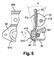
複数のセンタリング装置は、ボルトによって複数のユニット(30)の端部に固定される。この目的のため、図6に示すように、センタリング装置の球状部分とともにショルダ(420)を形成するように、センタリング装置の球状部分を延長してねじ付きピン(410)が形成される。ピン(410)は、航空機構造体との接合部分側のロッキングユニット(30)の端部にある孔(340)に適応され、このピンの端部にねじ止めされたナット(42)によって適切な位置に保持される。センタリング装置のショルダ(420)は、ロッキングユニット(30)の前面(320)に接触する。この前面(320)は、レドームの組付け平面(10)と平行であり、理想的にはこの平面に含まれる。 The plurality of centering devices are fixed to the ends of the plurality of units (30) by bolts. To this end, as shown in FIG. 6, the spherical portion of the centering device is extended to form a threaded pin (410) so as to form a shoulder (420) with the spherical portion of the centering device. The pin (410) is adapted to a hole (340) at the end of the locking unit (30) on the side of the interface with the aircraft structure, and is secured by a nut (42) screwed to the end of this pin. Held in position. The shoulder (420) of the centering device contacts the front surface (320) of the locking unit (30). This front face (320) is parallel to and ideally included in the radome assembly plane (10).
フック用接続ブラケット(70)は、ロッキングピン(710)の半径方向距離をレドームの長手軸に対して調整可能にする溝付き接合部分面(520)を用いてリセプタクルブラケット(50)に接続される。フックの取付けポイントは、レドームの表面に対して半径方向に出来るだけ近接して配置されると有利である。レドームの長手方向には、ロッキングピン(710)が、複数のユニット(30)の前面上の複数のセンタリング装置のベアリング面(320)に出来るだけ近接して配置される。理想的には、所与のユニットに関して、ロッキングピンの長手方向は、図5に示すセンタリング球体にかかる合力の方向円錐内に配置される。この円錐角γの頂点は、球体の長手軸と前記ユニット上の球体のベアリング面(320)との交差点に位置される。これらの位置決め原理は、レドームの構造体における曲げモーメントを減少出来、従って、取付装置の質量を減少可能であることを意味する。実際的観点から、ロッキングユニット上の前記球体のベアリング面(320)と前記フック受けピン(710)との長手方向距離が30mm未満の場合にこの条件が満たされる。 The hook connection bracket (70) is connected to the receptacle bracket (50) using a grooved joint surface (520) that allows the radial distance of the locking pin (710) to be adjusted relative to the longitudinal axis of the radome. . Advantageously, the hook attachment points are located as close as possible to the radome surface in the radial direction. In the longitudinal direction of the radome, the locking pins (710) are arranged as close as possible to the bearing surfaces (320) of the centering devices on the front face of the units (30). Ideally, for a given unit, the longitudinal direction of the locking pin is located within a directional cone of resultant force on the centering sphere shown in FIG. The apex of this cone angle γ is located at the intersection of the longitudinal axis of the sphere and the bearing surface (320) of the sphere on the unit. These positioning principles mean that the bending moment in the radome structure can be reduced and thus the mass of the mounting device can be reduced. From a practical point of view, this condition is met when the longitudinal distance between the bearing surface (320) of the sphere on the locking unit and the hook receiving pin (710) is less than 30 mm.
球体(50)によって、航空機構造体とレドームとの間で、半径方向位置決め、及び半径方向及び環状方向の力の伝達が確実に行われる。フックを用いるロック(20)によって、長手方向取付けが確実に行われ、気密性及び空気力学的連続性が確保されるようにレドームと航空機構造体との接合部分が圧迫される。フックの取付けピン(710)をユニット上の球体のベアリング面(320)に長手方向により近接させることによって、フックが操作される時の複数の球体の、そのハウジング内での支えを得ることが出来る。センタリング装置は、ロッキングフックが牽引力を加えている時、レドームを軸方向に保持することにも寄与する。 The sphere (50) ensures radial positioning and transmission of radial and annular forces between the aircraft structure and the radome. A lock (20) using a hook ensures a longitudinal attachment and compresses the joint between the radome and the aircraft structure to ensure hermeticity and aerodynamic continuity. By placing the hook mounting pin (710) closer to the ball bearing surface (320) of the sphere on the unit in the longitudinal direction, it is possible to obtain support within the housing of the spheres when the hook is operated. . The centering device also contributes to holding the radome in the axial direction when the locking hook is applying traction.
このように、航空機構造体と完全に水平な状態を確保しつつ、レドームを容易且つ迅速に開放可能であるように、これらの様々な手段が協働する。実際には、航空機構造体に対するレドームのセンタリングは、スロット(200、100)によってもたらされるレドームの形状の順応性によって確実に行われる。このように、これらのセンタリング装置(40)は、調整可能なリセプタクル(510)に取付け可能であり、結果的に遊びを含まず取付けられる。従って、センタリング装置は、航空機との接合部分に効果的にせん断力を伝達することが出来、従って、レドームが、迅速且つ容易に操作可能な一連の牽引フックロックによって航空機の機体に接続されることが出来る。 In this way, these various means work together so that the radome can be opened easily and quickly while still being perfectly level with the aircraft structure. In practice, the centering of the radome relative to the aircraft structure is ensured by the conformability of the radome shape provided by the slots (200, 100). In this way, these centering devices (40) can be attached to the adjustable receptacle (510) and consequently free of play. Thus, the centering device can effectively transmit shear forces to the aircraft interface, so that the radome is connected to the aircraft fuselage by a series of tow hook locks that can be operated quickly and easily. I can do it.
図7及び図8において、航空機機体と前記レドーム接合部分端との間の接合部分の周縁上にはシール(80、81)が配置される。好ましくは、シールを固定するために構造体に形成された溝又は孔内へのクリッピングによってシールは航空機構造体(C0)に固定される。シール(80、81)の他端は、レドームの端部のモノリシック部分(11)に接合部分平面(10)に対して垂直に形成された溝(110)に収納される。レドームの端部を航空機に対して長手方向に近接させるという複数のロック(20)の作用によって、溝上のシールが押し込まれ、従って、レドームの周縁の密閉性が確保され、更にシールが溝(110)内で保護される。 7 and 8, seals (80, 81) are arranged on the periphery of the joint portion between the aircraft body and the radome joint portion end. Preferably, the seal is secured to the aircraft structure (C0) by clipping into a groove or hole formed in the structure to secure the seal. The other end of the seal (80, 81) is accommodated in a groove (110) formed in the monolithic portion (11) at the end of the radome perpendicularly to the joint portion plane (10). The action of a plurality of locks (20) that bring the end of the radome closer to the aircraft in the longitudinal direction pushes the seal on the groove, thus ensuring the sealing of the periphery of the radome, and the seal is further on the groove (110 ) Protected within.
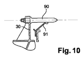
図9及び図10において、航空機構造体上へのレドーム(1)の設置は、事前センタリング装置によってより容易になる。これらの事前センタリング装置は、各々、ピン(90)、及びこのピン(90)を収容するように設計された中心孔を含み且つこの孔に対する位置及び方向が僅かにずれているピン(90)を支持するのに十分な半径方向の柔軟性を示すエラストマー製ワッシャ(91)を含む。図9に示すように、事前センタリングピン(90)は、航空機構造体上に設置され、複数のエラストマーワッシャ(91)はロッキングユニット上に設置される。或いは、図10に示すように、事前センタリングピン(90)はロッキングユニット(30)に固定され、エラストマーワッシャ(91)は航空機構造体に固定される。ピン(90)及びエラストマーワッシャ(91)の長さ及び位置は、球状センタリング装置が夫々のリセプタクルに進入する前にピンがワッシャに進入するような長さ及び位置である。このタイプの少なくとも4つの事前センタリング装置を接合部分端でレドームの円周周りに配置し、分布させると有利である。 9 and 10, the installation of the radome (1) on the aircraft structure is made easier by the pre-centering device. Each of these pre-centering devices includes a pin (90) and a pin (90) that includes a central hole designed to receive the pin (90) and is slightly offset in position and orientation relative to the hole. It includes an elastomer washer (91) that exhibits sufficient radial flexibility to support. As shown in FIG. 9, the pre-centering pin (90) is installed on the aircraft structure and the plurality of elastomer washers (91) are installed on the locking unit. Alternatively, as shown in FIG. 10, the pre-centering pin (90) is secured to the locking unit (30) and the elastomer washer (91) is secured to the aircraft structure. The length and position of the pin (90) and the elastomer washer (91) are such that the pin enters the washer before the spherical centering device enters the respective receptacle. Advantageously, at least four pre-centering devices of this type are arranged and distributed around the circumference of the radome at the junction end.
図11において、有益な実施形態によれば、好ましくは前記レドームの上部に位置する事前センタリングピン(900)のうちの2つが、フック形状を有し、対応するロッキングユニット(300)の基部に固定される。これらの特殊なピンは、他の事前センタリングピン(90)を収容するワッシャ(91)と比較して、半径方向の弾性が減少したエラストマーワッシャ(93)の中心に配置される。これらのピン(900)の特殊な形状とは、ピン(900)がレドームを開放するためのヒンジとして使用可能であるということであり、従って、レドームを取り外すことなくレーダにアクセスできるようにレドームを開放可能である。 In FIG. 11, according to an advantageous embodiment, two of the pre-centering pins (900), preferably located at the top of the radome, have a hook shape and are fixed to the base of the corresponding locking unit (300). Is done. These special pins are placed in the center of an elastomer washer (93) with reduced radial elasticity compared to a washer (91) that houses other pre-centering pins (90). The special shape of these pins (900) is that the pin (900) can be used as a hinge to open the radome, so the radome can be accessed so that the radar can be accessed without removing the radome. It can be opened.
以上の記述は、本発明の様々な特徴及びその利益を介して、本発明がそれ自体で設定した目的を実現することを明確に説明するものである。特に、本発明は、質量の点で不利益をもたらすことなく迅速に開放又は除去可能である点は維持しつつ、機体に適応させ且つ水平に保たせる質を向上させたレドームを製造可能にする。 The foregoing description clearly illustrates that the present invention achieves its intended purpose through the various features and benefits of the present invention. In particular, the present invention makes it possible to produce a radome with an improved quality that can be adapted to the aircraft and kept level while maintaining the point that it can be quickly opened or removed without penalizing in terms of mass. .
1 レドーム
10 (機体の)接合部分端/組付け平面
11 (剛性)モノリシックリング
12 二重曲率面
20 ロッキング装置(ロック)
21 (ラッチ)フック
22 接着及び樹脂性ウェッジ
30 (ロッキング)ユニット
31 基部
40 (球状)センタリング装置
42 ナット
50 リセプタクルブラケット/球体
51 フック
70 フック用接続ブラケット
80 シール
81 シール
90 (センタリング)ピン
91、93 エラストマー製ワッシャ
100 スロット
110 溝
200 スロット/(ロック配置)ノッチ
300 ロッキングユニット
320 (ロッキングユニットの)前面/(球体の)ベアリング面
340 孔
410 ピン
420 ショルダ
510 (円錐状)リセプタクル
520 線条領域(溝付き接合部分面)
710 ロッキング(取付け)ピン
900 (事前センタリング)ピン
1 radome 10 (of the fuselage) joint end / assembly plane 11 (rigid)
21 (Latch)
710 Locking (mounting) pin 900 (pre-centering) pin
Claims (13)
−取付手段を介して、前記機体の表面に対して略垂直方向に、前記表面へ牽引力を発揮可能なロッキング手段(20、21、70、710)と、
−前記機体とレドームの対向する面に対して略接線方向のせん断力に耐えることが出来るセンタリング手段(40、510)とを含み、
−前記ロッキング手段(20、21、70、710)は、前記レドーム(1)内のアセンブリによって発生する曲げ応力を最小にするように前記センタリング手段(40、510)にかかる合力の円錐内に位置するように配置される、レドーム(1)。 An aircraft radome (1), comprising a plurality of locking units (30) capable of joining opposite surfaces of the aircraft body and the radome (1), each of the units (30) comprising:
A locking means (20, 21, 70, 710) capable of exerting a traction force on the surface in a direction substantially perpendicular to the surface of the airframe via the attaching means;
-Centering means (40, 510) capable of withstanding shear forces in a substantially tangential direction with respect to the opposing surfaces of the airframe and radome;
The locking means (20, 21, 70, 710) are located within a cone of resultant forces on the centering means (40, 510) so as to minimize bending stresses generated by the assembly in the radome (1). A radome (1), arranged to
−前記レドームの端部をテンプレートに配置し、接合部分端の形状及び周長をテンプレートに適応させるステップと、
−前記レドームの端部の形状を固めるように前記レドームが前記テンプレート上にある間に前記各スロットに沿って複数のロッキングユニット(30)を固定するステップと
を含む、請求項1乃至10のいずれか1項に記載の複合材料のレドーム(1)の製造方法。 Cutting the plurality of slots (200, 100) by machining at the end of the radome;
-Placing the end of the radome into the template and adapting the shape and circumference of the joint end to the template;
Fixing a plurality of locking units (30) along each of the slots while the radome is on the template so as to consolidate the shape of the end of the radome. A manufacturing method of the radome (1) of the composite material according to claim 1.
−この構造体の端部にモノリシックリング(11)を接合するステップと、
を含む請求項11に記載の方法。 Molding the composite structure (12) into the shape of the radome constituted by two thermoplastic or thermosetting matrix composite panels separated by a honeycomb core;
Joining the monolithic ring (11) to the end of the structure;
The method of claim 11 comprising:
Applications Claiming Priority (3)
| Application Number | Priority Date | Filing Date | Title |
|---|---|---|---|
| FR0956267 | 2009-09-11 | ||
| FR0956267A FR2950199B1 (en) | 2009-09-11 | 2009-09-11 | RADOME AND DEVICE FOR FIXING THIS RADOME TO AN AIRCRAFT |
| PCT/FR2010/051896 WO2011030078A1 (en) | 2009-09-11 | 2010-09-10 | Radome and device for attaching said radome to an aircraft |
Publications (1)
| Publication Number | Publication Date |
|---|---|
| JP2013504468A true JP2013504468A (en) | 2013-02-07 |
Family
ID=41268206
Family Applications (1)
| Application Number | Title | Priority Date | Filing Date |
|---|---|---|---|
| JP2012528435A Pending JP2013504468A (en) | 2009-09-11 | 2010-09-10 | Radome and apparatus for attaching the radome to an aircraft |
Country Status (7)
| Country | Link |
|---|---|
| US (1) | US8816916B2 (en) |
| EP (1) | EP2476162B1 (en) |
| JP (1) | JP2013504468A (en) |
| CN (1) | CN102576931B (en) |
| CA (1) | CA2773532C (en) |
| FR (1) | FR2950199B1 (en) |
| WO (1) | WO2011030078A1 (en) |
Families Citing this family (12)
| Publication number | Priority date | Publication date | Assignee | Title |
|---|---|---|---|---|
| US8773300B2 (en) * | 2011-03-31 | 2014-07-08 | Raytheon Company | Antenna/optics system and method |
| US9614272B2 (en) | 2013-04-09 | 2017-04-04 | The Boeing Company | Aircraft antenna mounting system |
| US9537207B2 (en) | 2014-12-11 | 2017-01-03 | Thales, Inc. | Antenna assembly with a multi-band radome and associated methods |
| US9531064B2 (en) | 2014-12-11 | 2016-12-27 | Thales, Inc. | Antenna assembly with attachment fittings and associated methods |
| RU2599078C1 (en) * | 2015-07-06 | 2016-10-10 | Российская Федерация, от имени которой выступает Министерство обороны Российской Федерации | Aircraft with antenna radome |
| US9835425B2 (en) * | 2015-08-14 | 2017-12-05 | Raytheon Company | Metallic nosecone with unitary assembly |
| US10059426B2 (en) * | 2016-04-29 | 2018-08-28 | Embraer S.A. | Quick connection assemblies especially useful for coupling aircraft antenna fairings to airframe structures |
| CN106143871A (en) * | 2016-07-09 | 2016-11-23 | 精功(绍兴)复合材料有限公司 | A kind of radome of fighter double leval jib opener |
| RU178019U1 (en) * | 2017-10-12 | 2018-03-19 | федеральное государственное бюджетное образовательное учреждение высшего образования "Национальный исследовательский университет "МЭИ" (ФГБОУ ВО "НИУ "МЭИ") | AERODYNAMIC VEHICLE VEHICLE |
| US11495880B2 (en) | 2019-04-18 | 2022-11-08 | Srg Global, Llc | Stepped radar cover and method of manufacture |
| CN110775247A (en) * | 2019-10-25 | 2020-02-11 | 中航西飞民用飞机有限责任公司 | Waterproof sealing structure and sealing method for aircraft radar cabin |
| CN114435581A (en) * | 2020-11-06 | 2022-05-06 | 空客直升机德国有限公司 | Radome housing and opening kinematics |
Citations (2)
| Publication number | Priority date | Publication date | Assignee | Title |
|---|---|---|---|---|
| US2894777A (en) * | 1956-12-03 | 1959-07-14 | Clark Hartwell | Preload latch |
| US20070045467A1 (en) * | 2004-06-29 | 2007-03-01 | Airbus France | Device and method for fastening an aircraft radome |
Family Cites Families (5)
| Publication number | Priority date | Publication date | Assignee | Title |
|---|---|---|---|---|
| JPH0885497A (en) * | 1994-09-16 | 1996-04-02 | Oomori Seikouki Kk | Positioning device for heavy article |
| US5820077A (en) * | 1995-09-26 | 1998-10-13 | Mcdonnell Douglas Technologies, Inc. | Aircraft radome and integral attaching structure |
| US6271464B1 (en) * | 1996-12-18 | 2001-08-07 | Raytheon Company | Electronic magnetic interference and radio frequency interference protection of airborne missile electronics using conductive plastics |
| FR2782495B1 (en) * | 1998-08-19 | 2000-11-10 | Aerospatiale | FRONT OF AIRPLANE STRUCTURE |
| EP1642139A1 (en) | 2003-07-08 | 2006-04-05 | Inverness Medical Switzerland GmbH | Particle agglutination detection method and device |
-
2009
- 2009-09-11 FR FR0956267A patent/FR2950199B1/en not_active Expired - Fee Related
-
2010
- 2010-09-10 CN CN201080045850.3A patent/CN102576931B/en not_active Expired - Fee Related
- 2010-09-10 CA CA2773532A patent/CA2773532C/en not_active Expired - Fee Related
- 2010-09-10 JP JP2012528435A patent/JP2013504468A/en active Pending
- 2010-09-10 WO PCT/FR2010/051896 patent/WO2011030078A1/en active Application Filing
- 2010-09-10 US US13/395,241 patent/US8816916B2/en not_active Expired - Fee Related
- 2010-09-10 EP EP10770551.9A patent/EP2476162B1/en active Active
Patent Citations (2)
| Publication number | Priority date | Publication date | Assignee | Title |
|---|---|---|---|---|
| US2894777A (en) * | 1956-12-03 | 1959-07-14 | Clark Hartwell | Preload latch |
| US20070045467A1 (en) * | 2004-06-29 | 2007-03-01 | Airbus France | Device and method for fastening an aircraft radome |
Also Published As
| Publication number | Publication date |
|---|---|
| EP2476162A1 (en) | 2012-07-18 |
| EP2476162B1 (en) | 2013-11-06 |
| CN102576931A (en) | 2012-07-11 |
| US20120212391A1 (en) | 2012-08-23 |
| FR2950199B1 (en) | 2011-08-26 |
| WO2011030078A1 (en) | 2011-03-17 |
| CN102576931B (en) | 2015-06-03 |
| FR2950199A1 (en) | 2011-03-18 |
| US8816916B2 (en) | 2014-08-26 |
| CA2773532A1 (en) | 2011-03-17 |
| CA2773532C (en) | 2017-08-22 |
Similar Documents
| Publication | Publication Date | Title |
|---|---|---|
| JP2013504468A (en) | Radome and apparatus for attaching the radome to an aircraft | |
| US8844869B2 (en) | Aircraft structural assembly and associated assembling method | |
| US8727268B2 (en) | Attachment device for aircraft engine and aircraft comprising at least one such device | |
| US9038951B2 (en) | Coupling assembly | |
| EP2711293B1 (en) | Adjustable payload enclosure for wing | |
| US7735780B2 (en) | Aircraft stringer clip and related methods | |
| US9102106B2 (en) | Method of making a sealed junction between aircraft parts | |
| US20070023573A1 (en) | Aircraft wing | |
| US20120267478A1 (en) | Aircraft including an internal partition | |
| US7997530B2 (en) | Airplane fairing panel adjustable fitting assembly, kit and method | |
| US20170129588A1 (en) | Truss-Reinforced Radome Crown Structure | |
| US20180134365A1 (en) | Aircraft component comprising a chiral lattice | |
| US11208215B2 (en) | Method for mounting an aircraft pylon | |
| US11554880B2 (en) | Tail tie-down | |
| US10132241B2 (en) | Method of producing suspension for a structure in a turbojet engine using a hyperstatic trellis with pre-stressed link elements | |
| CN108116650A (en) | Fuselage skin panel connects system and the method for connecting skin panel | |
| US20180222591A1 (en) | Energy absorbing assembly for aircraft seat | |
| US10858114B2 (en) | Assembly for an aircraft, the assembly comprising a pylon and a front engine mount | |
| US10830376B2 (en) | Composite structure having an integrated support | |
| CN109693779A (en) | Aircraft windscreen with the glass and transfers loads and distribution washer that are integrated with flange | |
| US9388615B2 (en) | Deformable stow box door hinge | |
| JP4390322B2 (en) | Honeycomb panel structure | |
| BR102014014075B1 (en) | PRESSURE BUILD, AND METHOD OF ASSEMBLY OF A PRESSURE BUILD ON AN AIRCRAFT |
Legal Events
| Date | Code | Title | Description |
|---|---|---|---|
| A621 | Written request for application examination |
Free format text: JAPANESE INTERMEDIATE CODE: A621 Effective date: 20130805 |
|
| A131 | Notification of reasons for refusal |
Free format text: JAPANESE INTERMEDIATE CODE: A131 Effective date: 20140529 |
|
| A977 | Report on retrieval |
Free format text: JAPANESE INTERMEDIATE CODE: A971007 Effective date: 20140529 |
|
| A601 | Written request for extension of time |
Free format text: JAPANESE INTERMEDIATE CODE: A601 Effective date: 20140804 |
|
| A602 | Written permission of extension of time |
Free format text: JAPANESE INTERMEDIATE CODE: A602 Effective date: 20140811 |
|
| A02 | Decision of refusal |
Free format text: JAPANESE INTERMEDIATE CODE: A02 Effective date: 20141119 |