EP2476162B1 - Radome and fastening device for this radom on an aircraft - Google Patents
Radome and fastening device for this radom on an aircraft Download PDFInfo
- Publication number
- EP2476162B1 EP2476162B1 EP10770551.9A EP10770551A EP2476162B1 EP 2476162 B1 EP2476162 B1 EP 2476162B1 EP 10770551 A EP10770551 A EP 10770551A EP 2476162 B1 EP2476162 B1 EP 2476162B1
- Authority
- EP
- European Patent Office
- Prior art keywords
- radome
- fuselage
- locking
- interface
- aircraft
- Prior art date
- Legal status (The legal status is an assumption and is not a legal conclusion. Google has not performed a legal analysis and makes no representation as to the accuracy of the status listed.)
- Active
Links
- 229920001971 elastomer Polymers 0.000 claims description 9
- 239000000806 elastomer Substances 0.000 claims description 9
- 230000002093 peripheral effect Effects 0.000 claims description 7
- 239000002131 composite material Substances 0.000 claims description 6
- 238000005452 bending Methods 0.000 claims description 5
- 238000000034 method Methods 0.000 claims description 3
- 238000003754 machining Methods 0.000 claims description 2
- 238000005520 cutting process Methods 0.000 claims 2
- 238000004519 manufacturing process Methods 0.000 claims 1
- 239000011159 matrix material Substances 0.000 claims 1
- 238000000465 moulding Methods 0.000 claims 1
- 229920001169 thermoplastic Polymers 0.000 claims 1
- 239000004416 thermosoftening plastic Substances 0.000 claims 1
- 230000002829 reductive effect Effects 0.000 description 7
- 238000007789 sealing Methods 0.000 description 5
- 230000008901 benefit Effects 0.000 description 4
- RTAQQCXQSZGOHL-UHFFFAOYSA-N Titanium Chemical compound [Ti] RTAQQCXQSZGOHL-UHFFFAOYSA-N 0.000 description 3
- 238000004873 anchoring Methods 0.000 description 3
- 230000000694 effects Effects 0.000 description 3
- 238000012423 maintenance Methods 0.000 description 3
- 239000000463 material Substances 0.000 description 3
- 239000010936 titanium Substances 0.000 description 3
- 229910052719 titanium Inorganic materials 0.000 description 3
- 230000009471 action Effects 0.000 description 2
- 230000015572 biosynthetic process Effects 0.000 description 2
- 238000009434 installation Methods 0.000 description 2
- 230000010354 integration Effects 0.000 description 2
- 230000000670 limiting effect Effects 0.000 description 2
- 229910052751 metal Inorganic materials 0.000 description 2
- 239000002184 metal Substances 0.000 description 2
- 238000011084 recovery Methods 0.000 description 2
- 238000010008 shearing Methods 0.000 description 2
- 229910000838 Al alloy Inorganic materials 0.000 description 1
- 229910000906 Bronze Inorganic materials 0.000 description 1
- RYGMFSIKBFXOCR-UHFFFAOYSA-N Copper Chemical compound [Cu] RYGMFSIKBFXOCR-UHFFFAOYSA-N 0.000 description 1
- 101100536354 Drosophila melanogaster tant gene Proteins 0.000 description 1
- 241000257303 Hymenoptera Species 0.000 description 1
- 241001080024 Telles Species 0.000 description 1
- ATJFFYVFTNAWJD-UHFFFAOYSA-N Tin Chemical compound [Sn] ATJFFYVFTNAWJD-UHFFFAOYSA-N 0.000 description 1
- 240000008042 Zea mays Species 0.000 description 1
- 230000006978 adaptation Effects 0.000 description 1
- 230000002411 adverse Effects 0.000 description 1
- 230000005540 biological transmission Effects 0.000 description 1
- 239000010974 bronze Substances 0.000 description 1
- 230000015556 catabolic process Effects 0.000 description 1
- 230000008859 change Effects 0.000 description 1
- 230000008094 contradictory effect Effects 0.000 description 1
- 229910052802 copper Inorganic materials 0.000 description 1
- 239000010949 copper Substances 0.000 description 1
- KUNSUQLRTQLHQQ-UHFFFAOYSA-N copper tin Chemical compound [Cu].[Sn] KUNSUQLRTQLHQQ-UHFFFAOYSA-N 0.000 description 1
- 238000006731 degradation reaction Methods 0.000 description 1
- 239000003822 epoxy resin Substances 0.000 description 1
- 239000000835 fiber Substances 0.000 description 1
- 238000010304 firing Methods 0.000 description 1
- 230000014759 maintenance of location Effects 0.000 description 1
- 239000013521 mastic Substances 0.000 description 1
- 230000007246 mechanism Effects 0.000 description 1
- 230000035699 permeability Effects 0.000 description 1
- 229920000647 polyepoxide Polymers 0.000 description 1
- 229920001021 polysulfide Polymers 0.000 description 1
- 239000005077 polysulfide Substances 0.000 description 1
- 150000008117 polysulfides Polymers 0.000 description 1
- 230000003014 reinforcing effect Effects 0.000 description 1
- 239000011347 resin Substances 0.000 description 1
- 229920005989 resin Polymers 0.000 description 1
- 238000004088 simulation Methods 0.000 description 1
- 230000003068 static effect Effects 0.000 description 1
- 238000012360 testing method Methods 0.000 description 1
- 238000012546 transfer Methods 0.000 description 1
- 238000012795 verification Methods 0.000 description 1
Images


Classifications
-
- H—ELECTRICITY
- H01—ELECTRIC ELEMENTS
- H01Q—ANTENNAS, i.e. RADIO AERIALS
- H01Q1/00—Details of, or arrangements associated with, antennas
- H01Q1/42—Housings not intimately mechanically associated with radiating elements, e.g. radome
-
- B—PERFORMING OPERATIONS; TRANSPORTING
- B64—AIRCRAFT; AVIATION; COSMONAUTICS
- B64C—AEROPLANES; HELICOPTERS
- B64C1/00—Fuselages; Constructional features common to fuselages, wings, stabilising surfaces or the like
- B64C1/36—Fuselages; Constructional features common to fuselages, wings, stabilising surfaces or the like adapted to receive antennas or radomes
-
- H—ELECTRICITY
- H01—ELECTRIC ELEMENTS
- H01Q—ANTENNAS, i.e. RADIO AERIALS
- H01Q1/00—Details of, or arrangements associated with, antennas
- H01Q1/27—Adaptation for use in or on movable bodies
- H01Q1/28—Adaptation for use in or on aircraft, missiles, satellites, or balloons
- H01Q1/281—Nose antennas
-
- Y—GENERAL TAGGING OF NEW TECHNOLOGICAL DEVELOPMENTS; GENERAL TAGGING OF CROSS-SECTIONAL TECHNOLOGIES SPANNING OVER SEVERAL SECTIONS OF THE IPC; TECHNICAL SUBJECTS COVERED BY FORMER USPC CROSS-REFERENCE ART COLLECTIONS [XRACs] AND DIGESTS
- Y10—TECHNICAL SUBJECTS COVERED BY FORMER USPC
- Y10T—TECHNICAL SUBJECTS COVERED BY FORMER US CLASSIFICATION
- Y10T29/00—Metal working
- Y10T29/49—Method of mechanical manufacture
- Y10T29/49002—Electrical device making
- Y10T29/49016—Antenna or wave energy "plumbing" making
Definitions
- the invention relates to a radome for an aircraft and more particularly to a device for fixing said radome to the structure of this aircraft.
- the magnetic permeability encourages the realization of composite material.
- the complexity of the shape and the definition of structural folds adapted to the impact resistance constraint lead to complex deformation of the assembly after firing and difficulties in adjusting the shape of the radome to that of the fuselage. This adjustment is all the more complex as it is in the presence of double curvature shapes and very rigid parts.
- the first is to integrate in the radome, at the interface with the fuselage, a rigid frame and metal whose shape is precisely made and fits the shape of the fuselage-side interface.
- This configuration is expensive, given the accuracy of implementation, and the presence of the metal part has an adverse effect on the mass.
- the rigidity of this peripheral zone allows the installation of opening mechanisms whose kinematics facilitates rapid access to the radar without removing the radome.
- Another solution described in the European patent EP1612139 in the name of the applicant, consists in producing a flexible mounting interface, without rigid part, linked to the fuselage by a plurality of fasteners distributed around the circumference.
- This configuration makes it possible to take advantage of the flexibility of the interface to adapt it to the shape of the fuselage by the plurality of fasteners.
- the disassembly and / or opening time of the radome is increased compared to the first solution because of the plurality of links to be undone and to restore each opening-closing of the radome.
- These fasteners are placed in large numbers in particular to compensate for the flexibility of the radome at the interface between it and the end of the fuselage.
- the invention aims to solve the shortcomings of the prior art by proposing a radome whose constitution and the mounting / opening device cooperate to ensure an improved quality of fit and outcrop with the fuselage, preserving a possibility opening or quick disassembly without disadvantage in terms of mass.
- the radome can be flexible to adapt to the shape of the fuselage in a perfect outcrop and the number of locking housings can be reduced so as not to excessively increase the time of assembly-disassembly of said radome.
- the invention can be implemented according to the advantageous embodiments described below, which can be considered individually or in any technically operative combination.
- the radome object of the invention comprises a longitudinal slot in its structure starting from the interface end with the fuselage.
- the radome comprises a plurality of longitudinal slots in its structure starting from the end of the interface with the fuselage e distributed on the circumference of this end the locking boxes each comprising a rigid support surface fixed to the radome and spanning both edges of a slot
- the number of slots is determined by the ability to accommodate both the shape and perimeter of the fuselage interface end depending on the shape, nature, and stiffness of that end. In practice it is fixed by numerical simulations associated if necessary with tests on prototype.
- the locking boxes act as fittings and make it possible to ensure the structural continuity of the interface and to drain the flow of forces without passing through said slots once the interface is adjusted.
- the combination of this structural role with the locking function makes it possible to limit the mass that would be added by specific force recovery fittings in the presence of the slots.
- the radome object of the invention comprises, starting from the interface end with the fuselage, a monolithic peripheral zone extending under each locking case, the remainder of the radome consisting of a nest structure. bees.
- This monolithic zone advantageously coextracted with the rest of the structure, gives the end of the radome rigidity, thus allowing its maintenance by a limited number of anchoring points and the possibilities of opening or retraction simplified, in particular by joints.
- this rigid peripheral zone is not made with particular precision and can be adjusted to the fuselage through the presence of the slots, which allows its realization in an economical manner.
- This rigidified peripheral zone may be advantageously used to integrate the sealing functions of the radome, in particular by practicing a groove receiving the end of a deformable seal attached to the fuselage.
- the integration of the means ensuring this sealing function in the thickness of the wall of the radome makes it possible to bring the locking means of said wall radially closer and thus to limit the effects of bending and shearing caused by the distance between the points applying forces on these locking means and the wall of the radome to which they are attached.
- the centering means are constituted by centralizers which are housed in receptacles on the fuselage side during the closing of said radome.
- these centralizers take up the shear stresses substantially parallel to the interface plane.
- either said locks can be selected type "quick lock” known from the prior art, including traction hook and allow locking and unlocking by one maneuver a lever flush with the outer surface of the radome. Thus they can be unlocked from outside the radome thus allowing easy access to the radar in a reduced downtime.
- This type of lock has a high resistance in the locking axis but reduced perpendicularly to this axis, reduced resistance compensated by the presence of the centering.
- the locking boxes are used to support the said centralizers, which provides an advantage in terms of mass by limiting the number of parts, but above all makes it possible to bring the said centralizers closer to the attachment points of the locking devices, thus facilitating the arching. clamping of the locking device and consequently the safety of said locking.
- At least two locking boxes comprise a device for prepositioning the radome with respect to the fuselage constituted by a pin that is housed in an elastomer washer.
- These devices facilitate the mounting of the radome.
- the elastomeric washers provide a location and a relative maintenance of the radome with respect to the fuselage before securely positioning and securing thereof by means of centering devices on the fuselage.
- the integration of this device to the locking boxes allows a saving in mass by limiting the number of fittings installed on the radome.
- Said housings can either receive the prepositioning pins or the elastomer washers, and this configuration can change from one housing to another. If the size or weight of the radome so justifies, four prepositioning pins of this type are used.
- At least two pins have a shape adapted to allow the articulation of the radome along an axis substantially parallel to the interface plane.
- the radome comprises only two prepositioning pins these will preferably be of this type. They thus serve as hinges for rapid opening of the radome without removing it.
- the lightness of the radome according to the invention makes it possible to achieve this articulation in the elastomer washers without installing fitting and clevis for the recovery of such a joint.
- Said pins being connected to the rigid housings, themselves attached to the peripheral zone monolithic also rigid, these two points of attachment are sufficient to keep the radome in the open position without risk of degradation of it under the effect of its own weight.
- the invention also relates to an aircraft comprising a radome corresponding to any one of the embodiments described above.
- the radome according to the invention (1) comprises a double curvature surface (12) made of a material permeable to electromagnetic waves, preferably composite in the form of a honeycomb. From the interface end (10) which is attached to the fuselage of the aircraft, it comprises a rigid monolithic ring (11) extending at the locations of the locking devices (20). This rigid monolithic ring maintains the coherence of shape of said radome especially during the opening thereof for example during verification or maintenance operations of the radar placed under the radome.
- This ring (11) also makes it possible to maintain the radome attached to the fuselage by a reduced number of anchoring points and locking the fuselage. In return, the rigidity of said crown does not allow perfect adjustment and flush of the shape of the interface end (10) to the shape of the fuselage.
- slots (100) are formed in the structure of the radome, starting from the interface end (10). and extending into the monolithic crown (11) and beyond. Said slots (100) are substantially perpendicular to the assembly interface, they allow to adjust it in both shape and perimeter.
- the slots (100) comprise two parts.
- a first portion (200) substantially rectangular and adapted to receive a latch (20) preferentially snap-type toggle, extends from the interface end, over a length adapted to allow the housing of the adapted locking device.
- This notch (200) is extended by a narrow slot (100).
- the adjustment of the radome to the fuselage in shape and perimeter can be performed directly on the aircraft to which said radome is intended or on a template.
- a female template on which the outer face of the radome (1) is plastered at the level of the monolithic ring (11).
- the slots provide sufficient flexibility to perform the calibration by controlling the portage of said crown on the template along its entire perimeter. After calibration the locking boxes (30), figures 3 and 4 , are fixed on the internal face of the radome to the right of the slots.
- the locking housings comprise a sole (31) of sufficient width to span the notch (200) of the lock placement and the slot (100). Once the boxes are fixed, they stiffen the ring (11) in the annular direction and cancel the flexibility provided by the slots and the notches. The radome therefore remains in the shape of the template.
- the radome is then extracted from the template, the locks (20) are installed in their locations.
- a glued and resinated shim (22) is placed in front of each latch to close the notch (200), the slits (100) are plugged with a polysulfide mastic or an epoxy resin filled with short fibers.
- the housings (30) are designed to withstand these stress flows.
- the monolithic part (11), at the interface end of the radome, is preferably extended under the flanges of the locking boxes (31).
- the range of the soleplate on the radome is adjusted by a compensation wedge by interposing resin between the sole of the housing and its bearing surface on the radome.
- the locking boxes consist of a high-performance aluminum alloy chosen from the 7000 series and are obtained by machining.
- the locking boxes are in the form of substantially prismatic hollow elements occupying a volume of the order of 500x300x300 mm 3 .
- the typical thickness of the wall of said housings is between 1.5 mm and 2.5 mm.
- the annular and longitudinal rigidity of such housings contributes to the structural strength of the radome, reinforcing the anchoring points with the structure of the aircraft and thus reducing the number of these anchor points.
- the number of anchors of this type can be reduced to 8 for the radome of a jumbo jet whose diameter of the interface end is of the order of 2 meters.
- the rigidity of the housings is advantageously used to group on these elements all the centering and locking functions of the radome on the structure of the aircraft.
- the radome is connected to the aircraft by spherical centralizers (40) and locking hooks (21).
- the two are connected to the structure of the aircraft preferably via receptacle fittings (50) each comprising a conical receptacle (510) of a taper of angle ⁇ / 2 for receiving the centering sphere.
- (40) of the locking housing opposite, and a grooved area (520) receiving the brackets connecting the hooks (51).
- the receptacle fittings (50) are for example made of titanium T40 and fixed to the structure of the aircraft by screws also made of titanium.
- Spherical centrers are preferably made of a malleable bronze-based material comprising copper, tin and lead having a low coefficient of friction with titanium and able to withstand static charges.
- the typical diameter of the spherical portion of the centralizers (40) is between 14 and 20 mm.
- the spherical portion of the centralizers is extended by a threaded axis (410), so as to form a shoulder (420) with the spherical portion of the centralizer.
- the axis (410) is fitted into a bore (340) at the end of the lock housing (30) on the interface side with the aircraft structure, and secured in position by a screwed nut (42). on the end of this axis.
- the shoulder (420) of the centralizer bears on the front face (320) of the lock housing (30). This front face (320) is parallel to the assembly plane (10) of the radome and ideally included in this plane.
- the bracket (70) connecting the hook is connected to the receptacle fitting (50) via a serrated interface (520) which makes it possible to adjust the radial distance from the attachment axis (710) with respect to the longitudinal axis of the radome.
- the attachment point of the hook is placed radially as close as possible to the surface of the radome.
- the attachment axis (710) is placed as close as possible to the support plane (320) centering on the front of the housings (30).
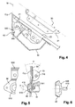
- the longitudinal position of the attachment axis is, for a given housing, in the direction cone of the resultant efforts on the centering sphere, figure 5 .
- this corner cone is placed on the intersection of the longitudinal axis of the sphere with the bearing plane (320) thereof on the housing.
- the spheres (50) provide radial positioning and transmission of radial and annular forces between the aircraft structure and the radome.
- the bolts (20), through the hooks, provide the longitudinal hooking and compress the interface between the radome and the structure of the aircraft to ensure sealing and aerodynamic continuity. Longitudinally bringing the hooking axis (710) of the hooks and the bearing plane (320) of the spheres on the housings makes it possible to obtain the arching of the spheres in their housing when the action of the hooks is exerted. .
- the centralizers also contribute to the axial retention of the radome when the locking hooks apply their traction.
- the different means cooperate to allow easy and fast opening of the radome while ensuring a perfect outcrop thereof with the structure of the aircraft.
- the centering of the radome with respect to the structure of the aircraft is ensured by the adaptability of its shape, provided by the slots (200,100).
- the centralizers (40) can be mounted in adjustable receptacles (510) and therefore be mounted without clearance. They can thus effectively take up the shear forces at the interface with the aircraft and thus allow the connection of the radome to the fuselage said aircraft by a series of latches traction hook, quickly and easily maneuverable.
- a seal (80, 81) is placed on the periphery of the interface between the aircraft structure and the interface end of the radome.
- the seal is fixed to the aircraft structure (C0) by snapping into a groove or into holes made for this purpose in said structure.
- the other end of the seal (80, 81) fits in a groove (110) made perpendicularly to the interface plane (10) in the monolithic portion (11) of the end of the radome.
- precentering devices each comprise a pin (90) and an elastomer washer (91) having a central bore adapted to receive said pin (90) and having a radial flexibility sufficient to withstand a slight shift in position in orientation of the pin ( 90) relative to this bore.
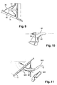
- the precenter pins (90) can be installed on the aircraft structure and the elastomer washers (91) on the lock boxes, figure 9 .
- the precenter pin (90) is attached to the lock housing (30) and the elastomer washer (91) to the aircraft structure.
- the length and position of the pins (90) and elastomer washers (91) is such that the pins enter the washers before the spherical centerpieces enter their receptacles.
- at least 4 precentering devices of this type are arranged and distributed over the circumference of the radome at the interface end.
- two of the pre-centering pins (900) preferably located on the upper part of the radome have a hook shape and are fixed to the sole of the corresponding locking housing (300). These particular pins are centered in elastomer washers (93) having a reduced radial resilience compared to those (91) receiving the other pre-centering pins (90).
- the particular shape of these pins (900) can be used as hinges for the opening of the radome, which can be opened to access the radar without the need to deposit.
- the present invention achieves the objectives it has set for itself.
- the invention allows the realization of a radome offering an improved quality of fit and outcrop with the fuselage, preserving a possibility of opening or dismounting quickly without disadvantage in terms of mass
Description
L'invention concerne un radôme pour aéronef et plus particulièrement un dispositif de fixation dudit radôme à la structure de cet aéronef.The invention relates to a radome for an aircraft and more particularly to a device for fixing said radome to the structure of this aircraft.
La plupart des aéronefs et plus particulièrement les avions de transport civil comprennent un radôme situé en pointe avant du fuselage. Outre son rôle aérodynamique, ce radôme protège également un radar. De ce fait il est constitué d'un matériau perméable aux ondes électromagnétiques, en général un matériau composite. Les fonctions de cette pièce impliquent plusieurs contraintes quant à sa conception et à sa réalisation :
- l'accessibilité au radar situé sous le radôme implique que celui-ci soit une pièce amovible et avantageusement facilement démontable ou escamotable ;
- son rôle de protection du radar et sa position dans une zone particulièrement exposée à différents types impacts, impose que cette pièce soit particulièrement résistante, mais aussi qu'elle soit étanche, tout comme sa liaison au fuselage ;
- sa position aérodynamique en pointe avant implique qu'elle se raccorde parfaitement à la forme du fuselage pour éviter toute formation de turbulences dans l'écoulement de l'air, consécutives à un mauvais affleurement.
- the accessibility to the radar located under the radome implies that it is a removable part and advantageously easily removable or retractable;
- its role in protecting the radar and its position in an area particularly exposed to different types of impact, requires that this part is particularly resistant, but also that it is waterproof, as its connection to the fuselage;
- its aerodynamic position in front tip implies that it connects perfectly to the shape of the fuselage to prevent any formation of turbulence in the flow of air, following a poor outcrop.
Ces exigences sont contradictoires à plus d'un titre. Par exemple, la perméabilité magnétique encourage la réalisation en matériau composite. Or, la complexité de la forme et la définition des plis structuraux adaptés à la contrainte de résistance aux impacts conduisent à des déformations complexes de l'ensemble après cuisson et des difficultés d'ajustement de la forme du radôme à celle du fuselage. Cet ajustement est d'autant plus complexe que l'on est en présence de formes en double courbure et de pièces très rigides.These requirements are contradictory in more ways than one. For example, the magnetic permeability encourages the realization of composite material. However, the complexity of the shape and the definition of structural folds adapted to the impact resistance constraint lead to complex deformation of the assembly after firing and difficulties in adjusting the shape of the radome to that of the fuselage. This adjustment is all the more complex as it is in the presence of double curvature shapes and very rigid parts.
Selon l'art antérieur, essentiellement deux méthodes de compromis entre ces différentes exigences sont utilisées. La première, consiste à intégrer au radôme, au niveau de l'interface avec le fuselage, un cadre rigide et métallique dont la forme est réalisée avec précision et s'ajuste à la forme de l'interface côté fuselage. Cette configuration est coûteuse, compte tenu de la précision de réalisation, et la présence de la pièce métallique produit un effet défavorable sur la masse. Cependant, la rigidité de cette zone périphérique permet l'installation de mécanismes d'ouverture dont la cinématique facilite un accès rapide au radar sans dépose du radôme.According to the prior art, essentially two methods of compromise between these different requirements are used. The first is to integrate in the radome, at the interface with the fuselage, a rigid frame and metal whose shape is precisely made and fits the shape of the fuselage-side interface. This configuration is expensive, given the accuracy of implementation, and the presence of the metal part has an adverse effect on the mass. However, the rigidity of this peripheral zone allows the installation of opening mechanisms whose kinematics facilitates rapid access to the radar without removing the radome.
Une autre solution, décrite dans le brevet européen
Le document
L'invention vise à résoudre les insuffisances de l'art antérieur en proposant un radôme dont la constitution et le dispositif de montage/ouverture coopèrent afin d'assurer une qualité d'ajustement et d'affleurement améliorée avec le fuselage, en préservant une possibilité d'ouverture ou de démontage rapide sans désavantage en termes de masse.The invention aims to solve the shortcomings of the prior art by proposing a radome whose constitution and the mounting / opening device cooperate to ensure an improved quality of fit and outcrop with the fuselage, preserving a possibility opening or quick disassembly without disadvantage in terms of mass.
À cette fin l'invention propose un radôme pour un aéronef lequel radôme comprend une pluralité de boîtiers de verrouillage aptes à rapprocher les faces en vis-à-vis du fuselage de l'aéronef et du radôme, chaque boîtier comportant :
- des moyens de verrouillage aptes à exercer sur la face du fuselage un effort de traction sensiblement normal à celle-ci par l'intermédiaire de moyens d'accrochage ;
- des moyens de centrage aptes à reprendre les efforts de cisaillement sensiblement tangents aux faces du fuselage et du radôme en vis-à-vis ;
- les moyens de verrouillage étant placés de telle manière qu'ils se trouvent à l'intérieur du cône des efforts résultants sur les moyens de centrage de sorte à minimiser les sollicitations de flexion générées par l'assemblage dans le radôme.
- locking means adapted to exert on the face of the fuselage a tensile force substantially normal to the latter by means of attachment means;
- centering means adapted to take up the shearing forces substantially tangent to the faces of the fuselage and the radome vis-à-vis;
- the locking means being placed in such a way that they are inside the cone of the resulting forces on the centering means so as to minimize the bending stresses generated by the assembly in the radome.
Ainsi, en minimisant les sollicitations de flexion dans le radôme et notamment à l'interface entre le radôme et le fuselage, le radôme peut être souple pour s'adapter à la forme du fuselage dans un affleurement parfait et le nombre de boîtiers de verrouillage peut être réduit afin de ne pas augmenter exagérément les temps de montage-démontage dudit radôme.Thus, by minimizing the bending stresses in the radome and in particular at the interface between the radome and the fuselage, the radome can be flexible to adapt to the shape of the fuselage in a perfect outcrop and the number of locking housings can be reduced so as not to excessively increase the time of assembly-disassembly of said radome.
L'invention peut être mise en oeuvre selon les modes de réalisation avantageux exposés ci-après, lesquels peuvent être considérés individuellement ou selon toute combinaison techniquement opérante.The invention can be implemented according to the advantageous embodiments described below, which can be considered individually or in any technically operative combination.
Avantageusement le radôme objet de l'invention comprend une fente longitudinale dans sa structure partant de l'extrémité d'interface avec le fuselage.Advantageously, the radome object of the invention comprises a longitudinal slot in its structure starting from the interface end with the fuselage.
Ainsi la souplesse de l'interface peut être augmentée.Thus the flexibility of the interface can be increased.
Selon un mode réalisation particulièrement avantageux le radôme comprend une pluralité de fentes longitudinales dans sa structure partant de l'extrémité de l'interface avec le fuselage e réparties sur la circonférence de cette extrémité les boîtiers de verrouillage comprenant chacun une surface d'appui rigide fixée au radôme et enjambant les deux bords d'une fenteAccording to a particularly advantageous embodiment, the radome comprises a plurality of longitudinal slots in its structure starting from the end of the interface with the fuselage e distributed on the circumference of this end the locking boxes each comprising a rigid support surface fixed to the radome and spanning both edges of a slot
Ainsi la présence de ces fentes permet conférer de la souplesse à la fois en forme et en périmètre à l'extrémité du radôme faisant interface avec le fuselage et ainsi d'obtenir un ajustement et un affleurement parfait des deux structures même si l'extrémité d'interface dudit radôme.Thus the presence of these slots allows to give flexibility both in shape and perimeter at the end of the radome interfacing with the fuselage and thus to obtain a perfect fit and flush of the two structures even if the end of interface of said radome.
Le nombre de fentes est déterminé par la capacité à permettre une adaptation à la fois en forme et en périmètre de l'extrémité d'interface avec le fuselage en fonction de la forme, de la nature et de la rigidité de cette extrémité. En pratique il est fixé par des simulations numériques associées si besoin à des essais sur prototype.The number of slots is determined by the ability to accommodate both the shape and perimeter of the fuselage interface end depending on the shape, nature, and stiffness of that end. In practice it is fixed by numerical simulations associated if necessary with tests on prototype.
Les boîtiers de verrouillage, dont une surface enjambe les bords desdites fentes, font office de ferrures et permettent d'assurer la continuité structurale de l'interface et de drainer les flux d'efforts sans passer par lesdites fentes une fois que l'interface est ajustée. La combinaison de ce rôle structural avec la fonction de verrouillage permet de limiter la masse qui serait ajoutée par des ferrures de reprise d'effort spécifique en présence des fentes.The locking boxes, a surface of which straddles the edges of said slots, act as fittings and make it possible to ensure the structural continuity of the interface and to drain the flow of forces without passing through said slots once the interface is adjusted. The combination of this structural role with the locking function makes it possible to limit the mass that would be added by specific force recovery fittings in the presence of the slots.
Avantageusement, le radôme objet de l'invention comprend, en partant de l'extrémité d'interface avec le fuselage, une zone périphérique monolithique se prolongeant sous chaque boîtier de verrouillage le reste du radôme étant constituée d'une structure en nid-d'abeilles. Cette zone monolithique, avantageusement cocuite avec le reste de la structure, confère à l'extrémité du radôme de la rigidité, autorisant ainsi son maintien par un nombre limité de points d'ancrage et des possibilités d'ouverture ou d'escamotage simplifiées, notamment par des articulations. Contrairement à l'art antérieur cette zone périphérique rigide n'est pas réalisée avec une précision particulière et peut être ajustée au fuselage grâce à la présence des fentes, ce qui autorise sa réalisation de manière économique.Advantageously, the radome object of the invention comprises, starting from the interface end with the fuselage, a monolithic peripheral zone extending under each locking case, the remainder of the radome consisting of a nest structure. bees. This monolithic zone, advantageously coextracted with the rest of the structure, gives the end of the radome rigidity, thus allowing its maintenance by a limited number of anchoring points and the possibilities of opening or retraction simplified, in particular by joints. Unlike the prior art this rigid peripheral zone is not made with particular precision and can be adjusted to the fuselage through the presence of the slots, which allows its realization in an economical manner.
Cette zone périphérique rigidifiée peut être avantageusement utilisée pour y intégrer les fonctions d'étanchéité du radôme, notamment en y pratiquant une rainure recevant l'extrémité d'un joint déformable fixé au fuselage. L'intégration des moyens assurant cette fonction d'étanchéité dans l'épaisseur de la paroi du radôme permet de rapprocher radialement les moyens de verrouillage de ladite paroi et ainsi de limiter les effets de flexion et de cisaillement parasites occasionnés par la distance entre les points d'application des efforts sur ces moyens de verrouillage et la paroi du radôme à laquelle ils sont fixés.This rigidified peripheral zone may be advantageously used to integrate the sealing functions of the radome, in particular by practicing a groove receiving the end of a deformable seal attached to the fuselage. The integration of the means ensuring this sealing function in the thickness of the wall of the radome makes it possible to bring the locking means of said wall radially closer and thus to limit the effects of bending and shearing caused by the distance between the points applying forces on these locking means and the wall of the radome to which they are attached.
Avantageusement, les moyens de centrage sont constitués par des centreurs qui viennent se loger dans des réceptacles côté fuselage lors de la fermeture dudit radôme. Outre l'avantage de faciliter un positionnement reproductible du radôme lors de chaque opération d'ouverture fermeture de celui-ci, ces centreurs reprennent les sollicitations de cisaillement sensiblement parallèles au plan d'interface.Advantageously, the centering means are constituted by centralizers which are housed in receptacles on the fuselage side during the closing of said radome. In addition to the advantage of facilitating a reproducible positioning of the radome during each closing opening operation thereof, these centralizers take up the shear stresses substantially parallel to the interface plane.
Ainsi, dans la mesure où les verrous n'assurent pas non plus de fonction de positionnement lesdits verrous peuvent être choisis de type « à verrouillage rapide » connus de l'art antérieur, notamment à crochet de traction et qui permettent le verrouillage et le déverrouillage par une seule manoeuvre d'un levier affleurant la surface externe du radôme. Ainsi ils peuvent être déverrouillés depuis l'extérieur du radôme permettant ainsi un accès facile au radar dans un temps d'immobilisation réduit. Ce type de verrou présente une résistance élevée dans l'axe de verrouillage mais réduite perpendiculairement à cet axe, résistance réduite compensée par la présence des centreurs.Thus, insofar as the locks do not provide a positioning function either said locks can be selected type "quick lock" known from the prior art, including traction hook and allow locking and unlocking by one maneuver a lever flush with the outer surface of the radome. Thus they can be unlocked from outside the radome thus allowing easy access to the radar in a reduced downtime. This type of lock has a high resistance in the locking axis but reduced perpendicularly to this axis, reduced resistance compensated by the presence of the centering.
Avantageusement les boîtiers de verrouillage sont utilisés pour supporter lesdits centreurs, ce qui procure un avantage en termes de masse en limitant le nombre de pièces, mais surtout permet de rapprocher lesdits centreurs des points d'accrochage des dispositifs de verrouillage facilitant ainsi l'arc-boutement du dispositif de verrouillage et par suite la sûreté dudit verrouillage.Advantageously, the locking boxes are used to support the said centralizers, which provides an advantage in terms of mass by limiting the number of parts, but above all makes it possible to bring the said centralizers closer to the attachment points of the locking devices, thus facilitating the arching. clamping of the locking device and consequently the safety of said locking.
Avantageusement au moins deux boîtiers de verrouillage comprennent un dispositif de prépositionnement du radôme par rapport au fuselage constitués par une broche venant se loger dans une rondelle en élastomère. Ces dispositifs facilitent le montage du radôme. Les rondelles en élastomères assurent une localisation et un maintien relatif du radôme par rapport au fuselage avant de positionner et fixer celui-ci de manière sécurisée par l'intermédiaire des centreurs sur le fuselage. L'intégration de ce dispositif aux boîtiers de verrouillage permet un gain de masse en limitant le nombre de ferrures installées sur le radôme. Lesdits boîtiers peuvent soit recevoir les broches de prépositionnement soit les rondelles en élastomère, et cette configuration peut changer d'un boîtier à l'autre. Si les dimensions ou le poids du radôme le justifient, quatre broches de prépositionnement de ce type sont utilisées.Advantageously, at least two locking boxes comprise a device for prepositioning the radome with respect to the fuselage constituted by a pin that is housed in an elastomer washer. These devices facilitate the mounting of the radome. The elastomeric washers provide a location and a relative maintenance of the radome with respect to the fuselage before securely positioning and securing thereof by means of centering devices on the fuselage. The integration of this device to the locking boxes allows a saving in mass by limiting the number of fittings installed on the radome. Said housings can either receive the prepositioning pins or the elastomer washers, and this configuration can change from one housing to another. If the size or weight of the radome so justifies, four prepositioning pins of this type are used.
Avantageusement, au moins deux broches ont une forme apte à permettre l'articulation du radôme selon un axe sensiblement parallèle au plan d'interface. Lorsque le radôme ne comprend que deux broches de prépositionnement celles-ci seront préférentiellement de ce type. Elles servent ainsi de charnières pour une ouverture rapide du radôme sans dépose de celui-ci. La légèreté du radôme selon l'invention permet de réaliser cette articulation dans les rondelles en élastomère sans installer de ferrure et de chape pour la reprise d'une telle articulation. Lesdites broches étant connectées aux boîtiers, rigides, eux-mêmes fixés à la zone périphérique monolithique également rigide, ces deux points d'accroche suffisent à maintenir le radôme en position ouverte sans risque de dégradation de celui-ci sous l'effet de son propre poids.Advantageously, at least two pins have a shape adapted to allow the articulation of the radome along an axis substantially parallel to the interface plane. When the radome comprises only two prepositioning pins these will preferably be of this type. They thus serve as hinges for rapid opening of the radome without removing it. The lightness of the radome according to the invention makes it possible to achieve this articulation in the elastomer washers without installing fitting and clevis for the recovery of such a joint. Said pins being connected to the rigid housings, themselves attached to the peripheral zone monolithic also rigid, these two points of attachment are sufficient to keep the radome in the open position without risk of degradation of it under the effect of its own weight.
L'invention concerne également un aéronef comprenant un radôme correspondant à l'un quelconque des modes de réalisation exposés ci-avant.The invention also relates to an aircraft comprising a radome corresponding to any one of the embodiments described above.
L'invention sera maintenant plus précisément décrite dans le cadre de ses modes de réalisation préférés, nullement limitatifs, représentés sur les
- la
figure 1 représente une vue d'ensemble de profil du radôme selon l'invention ; - la
figure 2 montre le radôme selon l'invention vue de face en perspective ; - la
figure 3 est une vue de détail de dessus du dispositif de connexion du radôme à la structure de l'aéronef ; - la
figure 4 est une vue en coupe selon un plan radial du radôme mettant en évidence le dispositif de verrouillage ; - la
figure 5 est une vue de détail de face et de profil des ferrures réceptacles fixées à l'interface de connexion côté aéronef ; - la
figure 6 est une vue en coupe des centreurs sphériques du radôme ; - les
figures 7 et 8 illustrent en coupe deux modes de réalisation du dispositif d'étanchéité de la périphérie du radôme à son extrémité d'interface avec la structure de l'aéronef ; - les
figures 9 et 10 illustrent en coupe selon un plan radial deux modes de réalisation du dispositif de précentrage du radôme lors de son assemblage avec la structure de l'aéronef - la
figure 11 représente un mode particulier de réalisation des broches du dispositif de précentrage pour une utilisation desdites broches en tant que charnières d'ouverture du radôme.
- the
figure 1 represents an overall profile view of the radome according to the invention; - the
figure 2 shows the radome according to the invention seen from the front in perspective; - the
figure 3 is a detail view from above of the connection device of the radome to the structure of the aircraft; - the
figure 4 is a sectional view along a radial plane of the radome highlighting the locking device; - the
figure 5 is a detailed view of the front and side of the receptacle fittings attached to the connection interface on the aircraft side; - the
figure 6 is a sectional view of the spherical centrometers of the radome; - the
Figures 7 and 8 illustrate in section two embodiments of the sealing device of the periphery of the radome at its interface end with the structure of the aircraft; - the
Figures 9 and 10 illustrate in section along a radial plane two embodiments of the pre-centering device of the radome during its assembly with the structure of the aircraft - the
figure 11 represents a particular embodiment of the pins of the precentering device for use of said pins as opening hinges of the radome.
La rigidité de cette couronne (11) permet aussi de maintenir le radôme fixé au fuselage par un nombre réduit de points d'ancrage et de verrouillage au fuselage. En contrepartie, la rigidité de ladite couronne ne permet pas un ajustement et un affleurement parfaits de la forme de l'extrémité d'interface (10) à la forme du fuselage. Afin de permettre l'adaptation en forme et en périmètre de la couronne d'interface du radôme au fuselage de l'aéronef, des fentes (100) sont pratiquées dans la structure du radôme, partant de l'extrémité d'interface (10) et se prolongeant dans la couronne monolithique (11) et au-delà. Lesdites fentes (100) sont sensiblement perpendiculaires à l'interface d'assemblage, elles permettent ainsi d'ajuster celle-ci tant en forme qu'en périmètre.The rigidity of this ring (11) also makes it possible to maintain the radome attached to the fuselage by a reduced number of anchoring points and locking the fuselage. In return, the rigidity of said crown does not allow perfect adjustment and flush of the shape of the interface end (10) to the shape of the fuselage. In order to allow the shape and perimeter adaptation of the radome interface ring to the fuselage of the aircraft, slots (100) are formed in the structure of the radome, starting from the interface end (10). and extending into the monolithic crown (11) and beyond. Said slots (100) are substantially perpendicular to the assembly interface, they allow to adjust it in both shape and perimeter.
L'ajustement du radôme au fuselage en forme et en périmètre peut être réalisé directement sur l'aéronef auquel ledit radôme est destiné ou sur un gabarit. Avantageusement, il est possible d'utiliser un gabarit femelle sur lequel on plaque la face extérieure du radôme (1) au niveau de la couronne monolithique (11). Les fentes donnent suffisamment de souplesse pour effectuer le calibrage en contrôlant le portage de ladite couronne sur le gabarit selon tout son périmètre. Après calibrage les boîtiers de verrouillage (30),
Le radôme est alors extrait du gabarit, les verrous (20) sont installés dans leurs emplacements. Une cale (22) collée et résinée est placée devant chaque verrou afin de fermer l'encoche (200), les fentes (100) sont bouchées avec un mastic à base de polysulfures ou par une résine époxyde chargée de fibres courtes.The radome is then extracted from the template, the locks (20) are installed in their locations. A glued and resinated shim (22) is placed in front of each latch to close the notch (200), the slits (100) are plugged with a polysulfide mastic or an epoxy resin filled with short fibers.
La semelle (31) des boîtiers de verrouillage enjambant les fentes (200,100) une fois lesdits boîtiers fixés au radôme, les flux d'effort circonférentiels et longitudinaux passent par lesdits boîtiers sans solliciter les fentes (200,100). Les boîtiers (30) sont conçus de sorte à résister à ces flux d'effort. Afin de favoriser ce transfert de charge, la partie monolithique (11), en extrémité d'interface du radôme, est de préférence prolongée sous les semelles des boîtiers de verrouillage (31). Pour chaque boîtier de verrouillage la portée de la semelle sur le radôme est ajustée par un calage de compensation en interposant de la résine entre la semelle du boîtier et sa surface d'appui sur le radôme.The sole (31) of the lock boxes spanning the slots (200,100) once said boxes fixed to the radome, the circumferential and longitudinal force flows through said housings without soliciting the slots (200,100). The housings (30) are designed to withstand these stress flows. In order to promote this charge transfer, the monolithic part (11), at the interface end of the radome, is preferably extended under the flanges of the locking boxes (31). For each lock housing the range of the soleplate on the radome is adjusted by a compensation wedge by interposing resin between the sole of the housing and its bearing surface on the radome.
Avantageusement les boîtiers de verrouillage sont constitués d'un alliage d'aluminium à haute performance choisi dans la série 7000 et sont obtenus par usinage. Selon cet exemple de réalisation, les boîtiers de verrouillage se présentent sous la forme d'éléments sensiblement prismatiques creux occupant un volume de l'ordre de 500x300x300 mm3. L'épaisseur typique de la paroi desdits boîtiers est comprise entre 1,5 mm et 2,5 mm. La rigidité annulaire et longitudinale de tels boîtiers participe à la tenue structurale du radôme, renforçant les points d'ancrage avec la structure de l'aéronef et permettant ainsi de réduire le nombre de ces points d'ancrage. Typiquement le nombre d'ancrages de ce type peut être réduit à 8 pour le radôme d'un avion gros porteur dont le diamètre de l'extrémité d'interface est de l'ordre de 2 mètres.Advantageously, the locking boxes consist of a high-performance aluminum alloy chosen from the 7000 series and are obtained by machining. According to this embodiment, the locking boxes are in the form of substantially prismatic hollow elements occupying a volume of the order of 500x300x300 mm 3 . The typical thickness of the wall of said housings is between 1.5 mm and 2.5 mm. The annular and longitudinal rigidity of such housings contributes to the structural strength of the radome, reinforcing the anchoring points with the structure of the aircraft and thus reducing the number of these anchor points. Typically the number of anchors of this type can be reduced to 8 for the radome of a jumbo jet whose diameter of the interface end is of the order of 2 meters.
Selon un mode de réalisation avantageux, le radôme est connecté à l'aéronef par des centreurs sphériques (40) et des crochets de verrouillage (21). Les deux sont connectés à la structure de l'aéronef de préférence par l'intermédiaire de ferrures réceptacles (50) comprenant chacune un réceptacle conique (510), d'une conicité d'angle γ/2, destiné à recevoir la sphère de centrage (40) du boîtier de verrouillage en vis à vis, et une zone striée (520) recevant les ferrures de liaison des crochets (51). Les ferrures réceptacles (50) sont par exemple réalisées en titane T40 et fixées à la structure de l'aéronef par des vis également en titane.According to an advantageous embodiment, the radome is connected to the aircraft by spherical centralizers (40) and locking hooks (21). The two are connected to the structure of the aircraft preferably via receptacle fittings (50) each comprising a conical receptacle (510) of a taper of angle γ / 2 for receiving the centering sphere. (40) of the locking housing opposite, and a grooved area (520) receiving the brackets connecting the hooks (51). The receptacle fittings (50) are for example made of titanium T40 and fixed to the structure of the aircraft by screws also made of titanium.
Les centreurs sphériques sont de préférence constitués d'un matériau à base de bronze malléable comprenant du cuivre, de l'étain et du plomb présentant un faible coefficient de frottement avec le titane et apte à supporter des charges statiques. Le diamètre typique de la partie sphérique des centreurs (40) est compris entre 14 et 20 mm.Spherical centrers are preferably made of a malleable bronze-based material comprising copper, tin and lead having a low coefficient of friction with titanium and able to withstand static charges. The typical diameter of the spherical portion of the centralizers (40) is between 14 and 20 mm.
Ils sont fixés aux extrémités des boîtiers (30) par boulonnage. À cette fin,
La ferrure (70) de liaison du crochet est connectée à la ferrure réceptacle (50) par l'intermédiaire d'une interface striée (520) qui permet de régler la distance radiale de l'axe d'accrochage (710) par rapport à l'axe longitudinal du radôme. Avantageusement, le point d'accrochage du crochet est placé radialement le plus proche possible de la surface du radôme. Selon la direction longitudinale l'axe d'accrochage (710) est placé le plus proche possible du plan d'appui (320) des centreurs sur la face avant des boîtiers (30). Idéalement, la position longitudinale de l'axe d'accrochage se trouve, pour un boîtier donné, dans le cône de direction de la résultante des efforts sur la sphère de centrage,
Les sphères (50) assurent le positionnement radial et la transmission des efforts radiaux et annulaires entre la structure de l'aéronef et le radôme. Les verrous (20), par l'intermédiaire des crochets, assurent l'accrochage longitudinal et compriment l'interface entre le radôme et la structure de l'aéronef pour en assurer l'étanchéité et la continuité aérodynamique. Rapprocher longitudinalement l'axe d'accrochage (710) des crochets et le plan d'appui (320) des sphères sur les boîtiers permet d'obtenir l'arc-boutement des sphères dans leur logement lorsque l'action des crochets s'exerce. Les centreurs contribuent ainsi également au maintien axial du radôme lorsque les crochets de verrouillage appliquent leur traction.The spheres (50) provide radial positioning and transmission of radial and annular forces between the aircraft structure and the radome. The bolts (20), through the hooks, provide the longitudinal hooking and compress the interface between the radome and the structure of the aircraft to ensure sealing and aerodynamic continuity. Longitudinally bringing the hooking axis (710) of the hooks and the bearing plane (320) of the spheres on the housings makes it possible to obtain the arching of the spheres in their housing when the action of the hooks is exerted. . The centralizers also contribute to the axial retention of the radome when the locking hooks apply their traction.
Ainsi les différents moyens coopèrent pour permettre une ouverture facile et rapide du radôme tout en assurant un affleurement parfait de celui-ci avec la structure de l'aéronef. En effet, le centrage du radôme par rapport à la structure de l'aéronef est assuré par l'adaptabilité de sa forme, procurée par les fentes (200,100). Ainsi, les centreurs (40) peuvent être montés dans des réceptacles ajustables (510) et par conséquent être montés sans jeu. Ils peuvent donc reprendre efficacement les efforts de cisaillement à l'interface avec l'aéronef et autorisent ainsi la connexion du radôme au fuselage dudit aéronef par une série de verrous à crochet de traction, rapidement et facilement manoeuvrables.Thus the different means cooperate to allow easy and fast opening of the radome while ensuring a perfect outcrop thereof with the structure of the aircraft. Indeed, the centering of the radome with respect to the structure of the aircraft is ensured by the adaptability of its shape, provided by the slots (200,100). Thus, the centralizers (40) can be mounted in adjustable receptacles (510) and therefore be mounted without clearance. They can thus effectively take up the shear forces at the interface with the aircraft and thus allow the connection of the radome to the fuselage said aircraft by a series of latches traction hook, quickly and easily maneuverable.
La description ci-avant illustre clairement que par ses différentes caractéristiques et leurs avantages, la présente invention atteint les objectifs qu'elle s'était fixés. En particulier, l'invention permet la réalisation d'u radôme offrant une qualité d'ajustement et d'affleurement améliorée avec le fuselage, en préservant une possibilité d'ouverture ou de démontage rapide sans désavantage en termes de masseThe above description clearly illustrates that by its different characteristics and advantages, the present invention achieves the objectives it has set for itself. In particular, the invention allows the realization of a radome offering an improved quality of fit and outcrop with the fuselage, preserving a possibility of opening or dismounting quickly without disadvantage in terms of mass
Claims (13)
- A radome (1) comprising an interface end intended to be assembled to an aircraft fuselage having catching means, characterised in that it includes a structure having multiple longitudinal slits (200, 100) coming from the interface end with the fuselage and returning over the circumference of this interface end and multiple locking cases (30) configured to bring the sides of the aircraft fuselage and the radome (1) opposite each other, each locking case (30) comprising:- locking means (20, 21, 70, 710) configured to exert a traction stress on the side of the fuselage, almost normal to the said side by the intermediary of the said catching means;- centring means (40, 510) configured to take back the cutting stresses, almost tangent to the sides of the fuselage and the radome opposite each other;- the locking means (20, 21, 70, 710) being placed on the inside of the stress cone, resulting on the centring means (40, 510) in order to minimise the bending stresses generated by the assembly in the radome (1).
- A radome according to the claim 1, wherein the locking cases (30) each include a stiff bearing surface fixed to the radome and span the two edges of a slit.
- A radome according to one of the claims 1 or 2, which includes, coming from the interface end with the fuselage (10), a monolithic peripheral area (11) extending under each locking case (30), the rest of the radome (12) being made up of a honeycomb structure.
- A radome according to one of the claims 1 to 3, characterised in that the peripheral area (11) includes, in the planar of the interface end (10), a groove (110) configured to receive the end of a flexible joint (80, 81) fixed to the fuselage.
- A radome according to one of the claims 1 to 4, characterised in that the centring means are made up of centralisers (40) placed in a planar including the interface with the fuselage and coming to lodge itself in a container (510) connected to the fuselage, when the said radome is in a closed position.
- A radome according to one of the claims 1 to 5, characterised in that the locking means are made up of a locking device (20) with a hook (21), which, in a locked position, exerts a stress on an axle (710) connected to the fuselage.
- A radome according to the claim 6, characterised in that the point of contact (710) of the hook with the fuselage and the fulcrum (410) of the centraliser on the locking case are distant in accordance with the longitudinal axle of the fuselage with a value of less or equal to 30mm.
- A radome according to one of any of the previous claims, characterised in that at least two locking cases include a pre-positioned device of the radome in relation to the fuselage under the form of a pin (90), coming to lodge itself in an elastomer washer (91).
- A radome according to the claim 8, characterised in that at least two of the said pins (900) have a hook shape, configured to allow the articulation of the radome in accordance with an axle almost parallel to the interface planar.
- A method for the production of a radome (1), according to one of any of the previous claims, in composite material, characterised in that it includes the steps, including:- cutting out the slits (200, 100) by machining, from the interface end of the said radome;- placing the interface end of the radome on a template and adjusting the shape and the perimeter of the interface end to the said template;- fixing the locking cases (30) to the right of each slit while the radome is on the template so as to set the shape of the interface end of the radome.
- A method according to the claim 10, characterised in that it includes the steps, including:- moulding a composite structure (12) to the shape of the radome made up of two thermoplastic or thermo hardening matrix composite panels, separated by a honeycomb core,- taking back a monolithic crown (11) to the end of this structure.
- An aircraft including a radome according to any one of the claims 1 to 9.
- An aircraft fuselage comprising, at its front, an opening to receive a radome according to one of the claims 1 to 9, and, at the edge of the said opening, catching means (50), configured to receive locking means (20, 21, 70, 710) of the cases of the radome.
Applications Claiming Priority (2)
| Application Number | Priority Date | Filing Date | Title |
|---|---|---|---|
| FR0956267A FR2950199B1 (en) | 2009-09-11 | 2009-09-11 | RADOME AND DEVICE FOR FIXING THIS RADOME TO AN AIRCRAFT |
| PCT/FR2010/051896 WO2011030078A1 (en) | 2009-09-11 | 2010-09-10 | Radome and device for attaching said radome to an aircraft |
Publications (2)
| Publication Number | Publication Date |
|---|---|
| EP2476162A1 EP2476162A1 (en) | 2012-07-18 |
| EP2476162B1 true EP2476162B1 (en) | 2013-11-06 |
Family
ID=41268206
Family Applications (1)
| Application Number | Title | Priority Date | Filing Date |
|---|---|---|---|
| EP10770551.9A Active EP2476162B1 (en) | 2009-09-11 | 2010-09-10 | Radome and fastening device for this radom on an aircraft |
Country Status (7)
| Country | Link |
|---|---|
| US (1) | US8816916B2 (en) |
| EP (1) | EP2476162B1 (en) |
| JP (1) | JP2013504468A (en) |
| CN (1) | CN102576931B (en) |
| CA (1) | CA2773532C (en) |
| FR (1) | FR2950199B1 (en) |
| WO (1) | WO2011030078A1 (en) |
Families Citing this family (12)
| Publication number | Priority date | Publication date | Assignee | Title |
|---|---|---|---|---|
| US8773300B2 (en) * | 2011-03-31 | 2014-07-08 | Raytheon Company | Antenna/optics system and method |
| US9614272B2 (en) | 2013-04-09 | 2017-04-04 | The Boeing Company | Aircraft antenna mounting system |
| US9537207B2 (en) | 2014-12-11 | 2017-01-03 | Thales, Inc. | Antenna assembly with a multi-band radome and associated methods |
| US9531064B2 (en) | 2014-12-11 | 2016-12-27 | Thales, Inc. | Antenna assembly with attachment fittings and associated methods |
| RU2599078C1 (en) * | 2015-07-06 | 2016-10-10 | Российская Федерация, от имени которой выступает Министерство обороны Российской Федерации | Aircraft with antenna radome |
| US9835425B2 (en) * | 2015-08-14 | 2017-12-05 | Raytheon Company | Metallic nosecone with unitary assembly |
| US10059426B2 (en) * | 2016-04-29 | 2018-08-28 | Embraer S.A. | Quick connection assemblies especially useful for coupling aircraft antenna fairings to airframe structures |
| CN106143871A (en) * | 2016-07-09 | 2016-11-23 | 精功(绍兴)复合材料有限公司 | A kind of radome of fighter double leval jib opener |
| RU178019U1 (en) * | 2017-10-12 | 2018-03-19 | федеральное государственное бюджетное образовательное учреждение высшего образования "Национальный исследовательский университет "МЭИ" (ФГБОУ ВО "НИУ "МЭИ") | AERODYNAMIC VEHICLE VEHICLE |
| US11495880B2 (en) | 2019-04-18 | 2022-11-08 | Srg Global, Llc | Stepped radar cover and method of manufacture |
| CN110775247A (en) * | 2019-10-25 | 2020-02-11 | 中航西飞民用飞机有限责任公司 | Waterproof sealing structure and sealing method for aircraft radar cabin |
| CN114435581A (en) * | 2020-11-06 | 2022-05-06 | 空客直升机德国有限公司 | Radome housing and opening kinematics |
Family Cites Families (7)
| Publication number | Priority date | Publication date | Assignee | Title |
|---|---|---|---|---|
| US2894777A (en) * | 1956-12-03 | 1959-07-14 | Clark Hartwell | Preload latch |
| JPH0885497A (en) * | 1994-09-16 | 1996-04-02 | Oomori Seikouki Kk | Positioning device for heavy article |
| US5820077A (en) * | 1995-09-26 | 1998-10-13 | Mcdonnell Douglas Technologies, Inc. | Aircraft radome and integral attaching structure |
| US6271464B1 (en) * | 1996-12-18 | 2001-08-07 | Raytheon Company | Electronic magnetic interference and radio frequency interference protection of airborne missile electronics using conductive plastics |
| FR2782495B1 (en) * | 1998-08-19 | 2000-11-10 | Aerospatiale | FRONT OF AIRPLANE STRUCTURE |
| CA2532023A1 (en) | 2003-07-08 | 2005-01-13 | Inverness Medical Switzerland Gmbh | Particle agglutination detection method and device |
| FR2872127B1 (en) * | 2004-06-29 | 2006-08-11 | Airbus France Sas | DEVICE AND METHOD FOR ATTACHING AN AIRCRAFT RADOME |
-
2009
- 2009-09-11 FR FR0956267A patent/FR2950199B1/en not_active Expired - Fee Related
-
2010
- 2010-09-10 CN CN201080045850.3A patent/CN102576931B/en not_active Expired - Fee Related
- 2010-09-10 WO PCT/FR2010/051896 patent/WO2011030078A1/en active Application Filing
- 2010-09-10 JP JP2012528435A patent/JP2013504468A/en active Pending
- 2010-09-10 CA CA2773532A patent/CA2773532C/en not_active Expired - Fee Related
- 2010-09-10 US US13/395,241 patent/US8816916B2/en not_active Expired - Fee Related
- 2010-09-10 EP EP10770551.9A patent/EP2476162B1/en active Active
Also Published As
| Publication number | Publication date |
|---|---|
| CN102576931B (en) | 2015-06-03 |
| EP2476162A1 (en) | 2012-07-18 |
| US20120212391A1 (en) | 2012-08-23 |
| JP2013504468A (en) | 2013-02-07 |
| FR2950199B1 (en) | 2011-08-26 |
| US8816916B2 (en) | 2014-08-26 |
| WO2011030078A1 (en) | 2011-03-17 |
| CN102576931A (en) | 2012-07-11 |
| FR2950199A1 (en) | 2011-03-18 |
| CA2773532A1 (en) | 2011-03-17 |
| CA2773532C (en) | 2017-08-22 |
Similar Documents
| Publication | Publication Date | Title |
|---|---|---|
| EP2476162B1 (en) | Radome and fastening device for this radom on an aircraft | |
| EP2106364B1 (en) | Section of aircraft fuselage and aircraft including one such section | |
| EP2139768B1 (en) | Aircraft engine attachment pylon that has an engine rear attachment fitted with a barrel nut | |
| EP2352673B1 (en) | Rigid aircraft pylon structure pressed against a side extension of the fuselage for the attachment thereof | |
| EP2242683B1 (en) | Monolithic, self-stiffened, and pivoting composite panel, in particular for a mobile part of an aircraft | |
| CA2742290C (en) | Aircraft structural assembly and associated assembly process | |
| EP3612445A1 (en) | Assembly for aircraft comprising a primary structure of an attachment pylon attached to a wing box using a bolted connection | |
| WO2011064519A2 (en) | Aircraft comprising an internal partition | |
| EP3219873B1 (en) | Reservation box for incorporating pipelines suitable for being positioned on a frame | |
| FR2953158A1 (en) | METHOD FOR REALIZING SEAL JUNCTION BETWEEN AIRCRAFT PARTS | |
| CA2777262A1 (en) | Assembly for holding the interface of stationary outer structure of a nacelle and housing of a jet engine | |
| FR2987401A1 (en) | METHOD FOR MAINTAINING AN ADAPTATION PART ON A TUBULAR HOUSING OF A TURBOMOTEUR, ADAPTATION PART AND CORRESPONDING HOLDING SYSTEM | |
| EP3505439B1 (en) | Assembly for aircraft comprising a mounting strut primary structure attached to a wing box by compact fasteners in the leading edge area | |
| FR2963320A1 (en) | Engine assembly i.e. turbofan assembly, for aircraft, has connection units ensuring passage of efforts along effort resumption directions defining effort resumption plane, where resumption plane and rod plane intercept along straight line | |
| EP0151542B1 (en) | Process and apparatus for provisionally increasing the opening of an aircraft fuselage structural frame | |
| WO2009147342A2 (en) | Mounting pylon for an aircraft engine including a box with a circle- or ellipsis-shaped cross-section | |
| FR3042779A1 (en) | METHOD FOR REPAIRING AN AIRCRAFT STRUCTURE FROM DEFORMABLE PLATES | |
| FR3053310A1 (en) | AIRCRAFT PROFILE WITH SIMPLIFIED MOBILE ZONE | |
| FR2966803A1 (en) | Sealing joint for use between rear secondary structure and aft pylon fairing of e.g. turbojet engine mounting structure of aircraft, has junction zone with section shrunk with respect to connection zone section to permit folding of joint | |
| EP3626610A1 (en) | Module for front landing gear for an aircraft | |
| EP0978660B1 (en) | Fastening device, consisting of a clamping device and of a fastening rod, for joining two parts to one another |
Legal Events
| Date | Code | Title | Description |
|---|---|---|---|
| PUAI | Public reference made under article 153(3) epc to a published international application that has entered the european phase |
Free format text: ORIGINAL CODE: 0009012 |
|
| 17P | Request for examination filed |
Effective date: 20120410 |
|
| AK | Designated contracting states |
Kind code of ref document: A1 Designated state(s): AL AT BE BG CH CY CZ DE DK EE ES FI FR GB GR HR HU IE IS IT LI LT LU LV MC MK MT NL NO PL PT RO SE SI SK SM TR |
|
| DAX | Request for extension of the european patent (deleted) | ||
| GRAP | Despatch of communication of intention to grant a patent |
Free format text: ORIGINAL CODE: EPIDOSNIGR1 |
|
| INTG | Intention to grant announced |
Effective date: 20130607 |
|
| GRAS | Grant fee paid |
Free format text: ORIGINAL CODE: EPIDOSNIGR3 |
|
| GRAA | (expected) grant |
Free format text: ORIGINAL CODE: 0009210 |
|
| AK | Designated contracting states |
Kind code of ref document: B1 Designated state(s): AL AT BE BG CH CY CZ DE DK EE ES FI FR GB GR HR HU IE IS IT LI LT LU LV MC MK MT NL NO PL PT RO SE SI SK SM TR |
|
| REG | Reference to a national code |
Ref country code: GB Ref legal event code: FG4D Free format text: NOT ENGLISH |
|
| REG | Reference to a national code |
Ref country code: CH Ref legal event code: EP |
|
| REG | Reference to a national code |
Ref country code: AT Ref legal event code: REF Ref document number: 639980 Country of ref document: AT Kind code of ref document: T Effective date: 20131215 |
|
| REG | Reference to a national code |
Ref country code: IE Ref legal event code: FG4D Free format text: LANGUAGE OF EP DOCUMENT: FRENCH |
|
| REG | Reference to a national code |
Ref country code: DE Ref legal event code: R096 Ref document number: 602010011587 Country of ref document: DE Effective date: 20131224 |
|
| REG | Reference to a national code |
Ref country code: NL Ref legal event code: VDEP Effective date: 20131106 |
|
| REG | Reference to a national code |
Ref country code: AT Ref legal event code: MK05 Ref document number: 639980 Country of ref document: AT Kind code of ref document: T Effective date: 20131106 |
|
| REG | Reference to a national code |
Ref country code: LT Ref legal event code: MG4D |
|
| PG25 | Lapsed in a contracting state [announced via postgrant information from national office to epo] |
Ref country code: NO Free format text: LAPSE BECAUSE OF FAILURE TO SUBMIT A TRANSLATION OF THE DESCRIPTION OR TO PAY THE FEE WITHIN THE PRESCRIBED TIME-LIMIT Effective date: 20140206 Ref country code: SE Free format text: LAPSE BECAUSE OF FAILURE TO SUBMIT A TRANSLATION OF THE DESCRIPTION OR TO PAY THE FEE WITHIN THE PRESCRIBED TIME-LIMIT Effective date: 20131106 Ref country code: HR Free format text: LAPSE BECAUSE OF FAILURE TO SUBMIT A TRANSLATION OF THE DESCRIPTION OR TO PAY THE FEE WITHIN THE PRESCRIBED TIME-LIMIT Effective date: 20131106 Ref country code: IS Free format text: LAPSE BECAUSE OF FAILURE TO SUBMIT A TRANSLATION OF THE DESCRIPTION OR TO PAY THE FEE WITHIN THE PRESCRIBED TIME-LIMIT Effective date: 20140306 Ref country code: FI Free format text: LAPSE BECAUSE OF FAILURE TO SUBMIT A TRANSLATION OF THE DESCRIPTION OR TO PAY THE FEE WITHIN THE PRESCRIBED TIME-LIMIT Effective date: 20131106 Ref country code: NL Free format text: LAPSE BECAUSE OF FAILURE TO SUBMIT A TRANSLATION OF THE DESCRIPTION OR TO PAY THE FEE WITHIN THE PRESCRIBED TIME-LIMIT Effective date: 20131106 Ref country code: LT Free format text: LAPSE BECAUSE OF FAILURE TO SUBMIT A TRANSLATION OF THE DESCRIPTION OR TO PAY THE FEE WITHIN THE PRESCRIBED TIME-LIMIT Effective date: 20131106 |
|
| PG25 | Lapsed in a contracting state [announced via postgrant information from national office to epo] |
Ref country code: ES Free format text: LAPSE BECAUSE OF FAILURE TO SUBMIT A TRANSLATION OF THE DESCRIPTION OR TO PAY THE FEE WITHIN THE PRESCRIBED TIME-LIMIT Effective date: 20131106 Ref country code: LV Free format text: LAPSE BECAUSE OF FAILURE TO SUBMIT A TRANSLATION OF THE DESCRIPTION OR TO PAY THE FEE WITHIN THE PRESCRIBED TIME-LIMIT Effective date: 20131106 Ref country code: AT Free format text: LAPSE BECAUSE OF FAILURE TO SUBMIT A TRANSLATION OF THE DESCRIPTION OR TO PAY THE FEE WITHIN THE PRESCRIBED TIME-LIMIT Effective date: 20131106 |
|
| PG25 | Lapsed in a contracting state [announced via postgrant information from national office to epo] |
Ref country code: PT Free format text: LAPSE BECAUSE OF FAILURE TO SUBMIT A TRANSLATION OF THE DESCRIPTION OR TO PAY THE FEE WITHIN THE PRESCRIBED TIME-LIMIT Effective date: 20140306 |
|
| PG25 | Lapsed in a contracting state [announced via postgrant information from national office to epo] |
Ref country code: EE Free format text: LAPSE BECAUSE OF FAILURE TO SUBMIT A TRANSLATION OF THE DESCRIPTION OR TO PAY THE FEE WITHIN THE PRESCRIBED TIME-LIMIT Effective date: 20131106 |
|
| REG | Reference to a national code |
Ref country code: DE Ref legal event code: R097 Ref document number: 602010011587 Country of ref document: DE |
|
| PG25 | Lapsed in a contracting state [announced via postgrant information from national office to epo] |
Ref country code: SK Free format text: LAPSE BECAUSE OF FAILURE TO SUBMIT A TRANSLATION OF THE DESCRIPTION OR TO PAY THE FEE WITHIN THE PRESCRIBED TIME-LIMIT Effective date: 20131106 Ref country code: PL Free format text: LAPSE BECAUSE OF FAILURE TO SUBMIT A TRANSLATION OF THE DESCRIPTION OR TO PAY THE FEE WITHIN THE PRESCRIBED TIME-LIMIT Effective date: 20131106 Ref country code: RO Free format text: LAPSE BECAUSE OF FAILURE TO SUBMIT A TRANSLATION OF THE DESCRIPTION OR TO PAY THE FEE WITHIN THE PRESCRIBED TIME-LIMIT Effective date: 20131106 Ref country code: CZ Free format text: LAPSE BECAUSE OF FAILURE TO SUBMIT A TRANSLATION OF THE DESCRIPTION OR TO PAY THE FEE WITHIN THE PRESCRIBED TIME-LIMIT Effective date: 20131106 |
|
| PLBE | No opposition filed within time limit |
Free format text: ORIGINAL CODE: 0009261 |
|
| STAA | Information on the status of an ep patent application or granted ep patent |
Free format text: STATUS: NO OPPOSITION FILED WITHIN TIME LIMIT |
|
| PG25 | Lapsed in a contracting state [announced via postgrant information from national office to epo] |
Ref country code: DK Free format text: LAPSE BECAUSE OF FAILURE TO SUBMIT A TRANSLATION OF THE DESCRIPTION OR TO PAY THE FEE WITHIN THE PRESCRIBED TIME-LIMIT Effective date: 20131106 |
|
| 26N | No opposition filed |
Effective date: 20140807 |
|
| REG | Reference to a national code |
Ref country code: DE Ref legal event code: R097 Ref document number: 602010011587 Country of ref document: DE Effective date: 20140807 |
|
| PG25 | Lapsed in a contracting state [announced via postgrant information from national office to epo] |
Ref country code: SI Free format text: LAPSE BECAUSE OF FAILURE TO SUBMIT A TRANSLATION OF THE DESCRIPTION OR TO PAY THE FEE WITHIN THE PRESCRIBED TIME-LIMIT Effective date: 20131106 |
|
| PG25 | Lapsed in a contracting state [announced via postgrant information from national office to epo] |
Ref country code: MC Free format text: LAPSE BECAUSE OF FAILURE TO SUBMIT A TRANSLATION OF THE DESCRIPTION OR TO PAY THE FEE WITHIN THE PRESCRIBED TIME-LIMIT Effective date: 20131106 Ref country code: LU Free format text: LAPSE BECAUSE OF FAILURE TO SUBMIT A TRANSLATION OF THE DESCRIPTION OR TO PAY THE FEE WITHIN THE PRESCRIBED TIME-LIMIT Effective date: 20140910 |
|
| REG | Reference to a national code |
Ref country code: CH Ref legal event code: PL |
|
| REG | Reference to a national code |
Ref country code: IE Ref legal event code: MM4A |
|
| PG25 | Lapsed in a contracting state [announced via postgrant information from national office to epo] |
Ref country code: BE Free format text: LAPSE BECAUSE OF NON-PAYMENT OF DUE FEES Effective date: 20140930 |
|
| PG25 | Lapsed in a contracting state [announced via postgrant information from national office to epo] |
Ref country code: CH Free format text: LAPSE BECAUSE OF NON-PAYMENT OF DUE FEES Effective date: 20140930 Ref country code: LI Free format text: LAPSE BECAUSE OF NON-PAYMENT OF DUE FEES Effective date: 20140930 |
|
| PG25 | Lapsed in a contracting state [announced via postgrant information from national office to epo] |
Ref country code: IE Free format text: LAPSE BECAUSE OF NON-PAYMENT OF DUE FEES Effective date: 20140910 |
|
| PG25 | Lapsed in a contracting state [announced via postgrant information from national office to epo] |
Ref country code: SM Free format text: LAPSE BECAUSE OF FAILURE TO SUBMIT A TRANSLATION OF THE DESCRIPTION OR TO PAY THE FEE WITHIN THE PRESCRIBED TIME-LIMIT Effective date: 20131106 |
|
| PG25 | Lapsed in a contracting state [announced via postgrant information from national office to epo] |
Ref country code: MT Free format text: LAPSE BECAUSE OF FAILURE TO SUBMIT A TRANSLATION OF THE DESCRIPTION OR TO PAY THE FEE WITHIN THE PRESCRIBED TIME-LIMIT Effective date: 20131106 Ref country code: BG Free format text: LAPSE BECAUSE OF FAILURE TO SUBMIT A TRANSLATION OF THE DESCRIPTION OR TO PAY THE FEE WITHIN THE PRESCRIBED TIME-LIMIT Effective date: 20131106 Ref country code: CY Free format text: LAPSE BECAUSE OF FAILURE TO SUBMIT A TRANSLATION OF THE DESCRIPTION OR TO PAY THE FEE WITHIN THE PRESCRIBED TIME-LIMIT Effective date: 20131106 Ref country code: GR Free format text: LAPSE BECAUSE OF FAILURE TO SUBMIT A TRANSLATION OF THE DESCRIPTION OR TO PAY THE FEE WITHIN THE PRESCRIBED TIME-LIMIT Effective date: 20140207 |
|
| PG25 | Lapsed in a contracting state [announced via postgrant information from national office to epo] |
Ref country code: TR Free format text: LAPSE BECAUSE OF FAILURE TO SUBMIT A TRANSLATION OF THE DESCRIPTION OR TO PAY THE FEE WITHIN THE PRESCRIBED TIME-LIMIT Effective date: 20131106 Ref country code: HU Free format text: LAPSE BECAUSE OF FAILURE TO SUBMIT A TRANSLATION OF THE DESCRIPTION OR TO PAY THE FEE WITHIN THE PRESCRIBED TIME-LIMIT; INVALID AB INITIO Effective date: 20100910 |
|
| REG | Reference to a national code |
Ref country code: FR Ref legal event code: PLFP Year of fee payment: 7 |
|
| REG | Reference to a national code |
Ref country code: FR Ref legal event code: PLFP Year of fee payment: 8 |
|
| PG25 | Lapsed in a contracting state [announced via postgrant information from national office to epo] |
Ref country code: MK Free format text: LAPSE BECAUSE OF FAILURE TO SUBMIT A TRANSLATION OF THE DESCRIPTION OR TO PAY THE FEE WITHIN THE PRESCRIBED TIME-LIMIT Effective date: 20131106 |
|
| REG | Reference to a national code |
Ref country code: FR Ref legal event code: PLFP Year of fee payment: 9 |
|
| PG25 | Lapsed in a contracting state [announced via postgrant information from national office to epo] |
Ref country code: AL Free format text: LAPSE BECAUSE OF FAILURE TO SUBMIT A TRANSLATION OF THE DESCRIPTION OR TO PAY THE FEE WITHIN THE PRESCRIBED TIME-LIMIT Effective date: 20131106 |
|
| PGFP | Annual fee paid to national office [announced via postgrant information from national office to epo] |
Ref country code: IT Payment date: 20190925 Year of fee payment: 10 |
|
| PGFP | Annual fee paid to national office [announced via postgrant information from national office to epo] |
Ref country code: DE Payment date: 20200925 Year of fee payment: 11 |
|
| PG25 | Lapsed in a contracting state [announced via postgrant information from national office to epo] |
Ref country code: IT Free format text: LAPSE BECAUSE OF NON-PAYMENT OF DUE FEES Effective date: 20200910 |
|
| REG | Reference to a national code |
Ref country code: DE Ref legal event code: R119 Ref document number: 602010011587 Country of ref document: DE |
|
| PG25 | Lapsed in a contracting state [announced via postgrant information from national office to epo] |
Ref country code: DE Free format text: LAPSE BECAUSE OF NON-PAYMENT OF DUE FEES Effective date: 20220401 |
|
| PGFP | Annual fee paid to national office [announced via postgrant information from national office to epo] |
Ref country code: GB Payment date: 20230920 Year of fee payment: 14 |
|
| PGFP | Annual fee paid to national office [announced via postgrant information from national office to epo] |
Ref country code: FR Payment date: 20230928 Year of fee payment: 14 |