EP2689973A2 - Key cylinder device - Google Patents
Key cylinder device Download PDFInfo
- Publication number
- EP2689973A2 EP2689973A2 EP13177550.4A EP13177550A EP2689973A2 EP 2689973 A2 EP2689973 A2 EP 2689973A2 EP 13177550 A EP13177550 A EP 13177550A EP 2689973 A2 EP2689973 A2 EP 2689973A2
- Authority
- EP
- European Patent Office
- Prior art keywords
- key
- mechanical key
- rotor
- mechanical
- guide
- Prior art date
- Legal status (The legal status is an assumption and is not a legal conclusion. Google has not performed a legal analysis and makes no representation as to the accuracy of the status listed.)
- Granted
Links
Images


Classifications
-
- B—PERFORMING OPERATIONS; TRANSPORTING
- B60—VEHICLES IN GENERAL
- B60R—VEHICLES, VEHICLE FITTINGS, OR VEHICLE PARTS, NOT OTHERWISE PROVIDED FOR
- B60R21/00—Arrangements or fittings on vehicles for protecting or preventing injuries to occupants or pedestrians in case of accidents or other traffic risks
- B60R21/01—Electrical circuits for triggering passive safety arrangements, e.g. airbags, safety belt tighteners, in case of vehicle accidents or impending vehicle accidents
- B60R21/015—Electrical circuits for triggering passive safety arrangements, e.g. airbags, safety belt tighteners, in case of vehicle accidents or impending vehicle accidents including means for detecting the presence or position of passengers, passenger seats or child seats, and the related safety parameters therefor, e.g. speed or timing of airbag inflation in relation to occupant position or seat belt use
- B60R21/01564—Manually or key-actuated inhibition switches
Definitions
- the present invention relates to a key cylinder device.
- a vehicle includes an airbag cutoff switch that selectively invalidates the deployment of an airbag when desired by a vehicle occupant (e.g., Japanese Laid-Open Patent Publication Nos. 2000-198410 , 8-216825 , and 11-227558 ).
- a mechanical key is used to switch the airbag cutoff switch between an activated state and a deactivated state.
- the mechanical key is normally used to lock and unlock a vehicle door and start the engine.
- an airbag cutoff switch device 100 which is one type of a key cylinder device, includes a rotor 101, a block 102, and a tubular case 103.
- the rotor 101 and the block 102 are rotatably accommodated in the case 103.
- a key groove 105 which corresponds to a mechanical key 110, extends along an inner surface of the rotor 101 and the block 102.
- the key groove 105 does not correspond to a unique key pattern 110a of the mechanical key 110. Rather, the key groove 105 corresponds to the type of the mechanical key 110.
- the key groove 105 is shaped to conform to different types of corresponding mechanical keys 110.
- the rotation of the rotor 101 switches connection conditions of contacts (not shown). This switches the airbag cutoff switch device between activated and deactivated states.
- the key groove 105 is shaped in conformance with different types of the mechanical key 110.
- the airbag cutoff switch device 100 has low versatility.
- One aspect of the present invention is a key cylinder device including a case having an inner surface.
- a rotor is accommodated in the case.
- the rotor includes a key groove into which a mechanical key is inserted, and the rotor is rotatable relative to the case about a rotation axis when the mechanical key is inserted into the key groove.
- a block extends through the rotor in a direction orthogonal to the rotation axis of the rotor.
- An urging portion urges the block toward the inner surface of the case to hold the block at an engagement position.
- the key groove has a size allowing for insertion of multiple types of mechanical keys corresponding to the key cylinder device.
- the key cylinder device includes a guide along which the mechanical key slides to correct inclination of the mechanical key relative to the rotation axis when the mechanical key is inserted into the key groove so that the mechanical key extends along the rotation axis of the rotor.
- the size of a key groove should conform to the larger ones of the mechanical keys.
- the mechanical key may become inclined in the key groove relative to the rotation axis.
- the block may not move to the disengagement position even though the mechanical key is inserted into the key groove.
- the guide corrects the inclination of the longitudinal direction of the mechanical key relative to the rotation axis.
- the longitudinal direction of the mechanical key conforms to the axial direction of the rotor.
- the block includes a key groove, which is in communication with the key groove of the rotor, and a contact portion, which contacts the mechanical key in the key groove of the block.
- a clearance allowing for entrance of a distal end of the mechanical key is formed between the guide and the contact portion. The distal end of the mechanical key enters the clearance and slides along the guide thereby correcting inclination of the mechanical key and pushing the contact portion toward the disengagement position as the mechanical key moves along the rotation axis of the rotor.
- the distal end of the mechanical key slides along the guide and corrects the inclination of the mechanical key.
- the mechanical key conforms to the rotation axis of the rotor, the mechanical key pushes the contact portion toward the disengagement position and moves the block to the disengagement position.
- the inclination correction of the mechanical key and the movement of the block are simultaneously performed.
- the clearance between the contact portion and the guide when the mechanical key is not inserted into the key groove of the rotor is set to be smaller than a length between the contact portion and the guide when inclination of the mechanical key is corrected by the guide by a distance between the engagement position and the disengagement position.
- a vehicle 1 includes an airbag cutoff switch device 20, a controller 11, and an airbag device 12.
- the controller 11 switches the airbag device 12 between an operational state and a non-operational state in accordance with whether the airbag cutoff switch device 20 is activated or deactivated.
- the airbag device 12 In the operational state, the airbag device 12 inflates an airbag upon detection of a strong impact applied to the vehicle 1.
- the non-operational state the airbag device 12 does not inflate the airbag regardless of impact detection.
- a mechanical key 15, which is held by a user, is used to switch the airbag cutoff switch device 20 between activated and deactivated states.
- the airbag cutoff switch device 20 includes a rotor 21, a block 24, and a case 26.
- the rotor 21 is cylindrical and rotatably accommodated in a tubular case 26.
- the rotor 21 and the block 24 respectively include key grooves 21a and 24a, which are in communication with each other.
- the key groove 21a of the rotor 21 opens toward a user.
- the key groove 21a of the present example is formed to be large to allow for the insertion of the mechanical keys corresponding to the key grooves of Figs. 9A to 9D described in the background of the invention.
- the mechanical key 15 portion of the mechanical key excluding the grip of the present example is an elongated plate and includes a key pattern 15b including valleys and ridges formed on opposite sides of the elongated plate.
- the airbag cutoff switch device 20 does not verify the key pattern 15b.
- the mechanical key 15 that switches the airbag cutoff switch device 20 may have different types of key patterns 15b. This is because the switching of the airbag cutoff switch device 20 does not require security as compared to the locking and unlocking of vehicle doors and the starting of the engine.
- the direction in which the mechanical key 15 is elongated is referred to as a longitudinal direction
- the direction orthogonal to the longitudinal direction is referred to as a widthwise direction.
- the rotor 21 includes a through hole 21b, which extends in a direction orthogonal to a rotation axis of the rotor 21 (vertical direction as viewed in Fig. 2 ).
- a key end 15a of the mechanical key 15 is arranged in the through hole 21b.
- a distal surface of the key end 15a (surface extending in the vertical direction that is orthogonal to the rotation axis of the rotor 21) contacts an inner wall 29 extending in a vertical direction of the rotor 21 (orthogonal to the rotation axis of the rotor 21).
- the block 24 has a generally frame-shaped cross-section.
- the block 24 has an inner surface forming the key groove 24a.
- the block 24 includes an upper portion that defines a block end 25 extending in an upward direction.
- the block 24 is received in the through hole 21b.
- a spring 30, which serves as an urging portion, is arranged between the block 24 and the rotor 21. The elastic force of the spring 30 urges the block 24 toward the inner surface of the case 26.
- the inner surface of the case 26 includes two engagement holes 26a and 26b that receive the block end 25.
- the block 24 is moved between an engagement position shown in Fig. 5A and a disengagement position shown in Fig. 5B .
- the block end 25 is fitted to the engagement hole 26a or 26b.
- the disengagement position the block end 25 is disengaged from the engagement holes 26a and 26b.
- the spring 30 urges the block 24 toward the inner surface of the case 26 and holds the block 24 at the engagement position.
- the engagement holes 26a and 26b are separated by a predetermined angle about the rotation axis of the rotor 21.
- the predetermined angle corresponds to the angle by which the mechanical key 15 is rotated to switch the airbag cutoff switch device 20 between activated and deactivated states.
- the rotor 21 includes a guide 22 that corrects the inclination of the mechanical key 15.
- the guide 22 is plate-shaped and located adjacent to the upper right side of the block 24.
- the guide 22 includes a distal end that projects into the key groove 24a as viewed in the axial direction.
- the distal end of the guide 22 projects radially inward from the inner surface of the block 24 forming the key groove 24a. This allows the distal end to come into contact with the key end 15a received in the key groove 24a. That is, the guide 22 is arranged at a position allowing for contact from the upper side with the key end 15a received in the key groove 24a.
- the key groove 24a of the block 24 includes a lower portion defining a contact portion 24c that comes into contact with the key end 15a.
- the contact portion 24c includes an inclined surface 24b that is inclined upward toward the right as viewed in Fig. 2 . That is, the inclined surface 24b is inclined upward toward the inner wall 29 of the rotor 21.
- L1 represents a length between the contact portion 24c and the guide 22 when the guide 22 corrects the inclination of the mechanical key
- L3 represents the distance between the engagement position and disengagement position of the block 24.
- the user first inserts the mechanical key 15 into the key groove 21a of the rotor 21.
- the mechanical key 15 is of a type having a small cross-section relative to the key groove 21a.
- the mechanical key 15 may enter the key grooves 21a and 24a so that the longitudinal direction is diagonally inclined toward the upper right side relative to the axial direction.
- the key end 15a of the mechanical key 15 contacts the guide 22.
- the key end 15a includes an inclined surface 15c that contacts the guide 22, and the inclined surface 15c is inclined upward toward the basal end of the mechanical key 15.
- the guide 22 lowers the mechanical key 15.
- the longitudinal direction of the mechanical key 15 conforms to the axial direction as shown in Fig. 3 .
- the inclination correction lowers the block 24 from the engagement position to the disengagement position against the elasticity of the spring 30.
- the key end 15a is in contact with three locations, namely, the inner wall 29, the guide 22, and the contact portion 24c.
- the block 24 is lowered from the engagement position to the disengagement position, rotation of the rotor 21 is permitted. This allows for the airbag cutoff switch device 20 to be switched between activated and deactivated states.
- the mechanical key 15 When the user inserts the mechanical key 15 into the key groove 21a of the rotor 21, the mechanical key 15 may enter the key grooves 21a and 24a so that the longitudinal direction is diagonally inclined toward the lower right side relative to the axial direction.
- the key end 15a of the mechanical key 15 contacts the inclined surface 24b of the contact portion 24c.
- Further insertion of the mechanical key 15 toward the right slides the key end 15a of the mechanical key 15 along the inclined surface 24b of the contact portion 24c.
- the longitudinal direction of the mechanical key 15 conforms to the axial direction and the inclination of the mechanical key 15 is corrected.
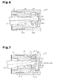
- Fig. 6 shows an airbag cutoff switch device that does not include the guide 22 for comparison with the present embodiment. Since this structure does not include the guide 22, the mechanical key 15 may remain inclined especially when the key pattern 15b has a smaller width than the key grooves 21a and 24a. In this case, the mechanical key 15 does not contact the contact portion 24c. Thus, the block 24 cannot be lowered to the disengagement position, and the rotor 21 cannot be rotated. As a result, the airbag cutoff switch device 20 cannot be switched between activated and deactivated states.
- a guide 40 may include a lower surface (surface that contacts the mechanical key 15) formed by an inclined surface 40a.
- the inclined surface 40a extends downward toward the right side as viewed in the drawing and is inclined by a predetermined inclination angle ⁇ relative to the rotation axis of the rotor 21. This structure ensures that the key end 15a is guided toward the rotation axis (downward) along the inclined surface 40a.
- a key cylinder device is applied as the airbag cutoff switch device 20.
- the key cylinder device may be applied for other applications.
- the above embodiment includes two engagement holes 26a and 26b. Instead, three or more engagement holes may be used depending on the application of the key cylinder device.
- the urging portion is the spring 30 but may be a different elastic member such as a rubber member.
Landscapes
- Engineering & Computer Science (AREA)
- Mechanical Engineering (AREA)
- Lock And Its Accessories (AREA)
Description
- The present invention relates to a key cylinder device.
- For safety reasons, a vehicle includes an airbag cutoff switch that selectively invalidates the deployment of an airbag when desired by a vehicle occupant (e.g., Japanese Laid-Open Patent Publication Nos.
2000-198410 8-216825 11-227558 - A mechanical key is used to switch the airbag cutoff switch between an activated state and a deactivated state. The mechanical key is normally used to lock and unlock a vehicle door and start the engine.
- For example, referring to
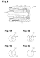
Fig. 8 , an airbagcutoff switch device 100, which is one type of a key cylinder device, includes arotor 101, ablock 102, and atubular case 103. Therotor 101 and theblock 102 are rotatably accommodated in thecase 103. Akey groove 105, which corresponds to amechanical key 110, extends along an inner surface of therotor 101 and theblock 102. Thekey groove 105 does not correspond to aunique key pattern 110a of themechanical key 110. Rather, thekey groove 105 corresponds to the type of themechanical key 110. Referring toFigs. 9A to 9D , thekey groove 105 is shaped to conform to different types of correspondingmechanical keys 110. - When the
mechanical key 110 is not inserted into thekey groove 105, theblock 102 is urged toward the inner surface (upper portion) of thecase 103. This restricts rotation of therotor 101. - When the
mechanical key 110 is inserted into thekey groove 105, the distal end of themechanical key 110 lowers theblock 102. This cancels the urging of theblock 102 so that therotor 101 is rotatable with themechanical key 110 relative to thecase 103. - The rotation of the
rotor 101 switches connection conditions of contacts (not shown). This switches the airbag cutoff switch device between activated and deactivated states. - In this structure, the
key groove 105 is shaped in conformance with different types of themechanical key 110. Thus, the airbagcutoff switch device 100 has low versatility. - Accordingly, it is an object of the present invention to provide a key cylinder device having higher versatility.
- One aspect of the present invention is a key cylinder device including a case having an inner surface. A rotor is accommodated in the case. The rotor includes a key groove into which a mechanical key is inserted, and the rotor is rotatable relative to the case about a rotation axis when the mechanical key is inserted into the key groove. A block extends through the rotor in a direction orthogonal to the rotation axis of the rotor. An urging portion urges the block toward the inner surface of the case to hold the block at an engagement position. When the mechanical key is not inserted into the key groove, the block located at the engagement position restricts rotation of the rotor relative to the case. When the mechanical key is inserted into the key groove along the rotation axis of the rotor, the mechanical key moves the block from the engagement position to a disengagement position in a direction opposite to the direction the block is urged and thereby permits rotation of the rotor relative to the case. The key groove has a size allowing for insertion of multiple types of mechanical keys corresponding to the key cylinder device. The key cylinder device includes a guide along which the mechanical key slides to correct inclination of the mechanical key relative to the rotation axis when the mechanical key is inserted into the key groove so that the mechanical key extends along the rotation axis of the rotor.
- To allow for insertion of multiple types of mechanical keys, the size of a key groove should conform to the larger ones of the mechanical keys. In this case, depending on the type of the mechanical key, when the key groove has a larger size than the mechanical key, the mechanical key may become inclined in the key groove relative to the rotation axis. As a result, the block may not move to the disengagement position even though the mechanical key is inserted into the key groove. In the above structure, however, even if the mechanical key is inclined in the key groove, the guide corrects the inclination of the longitudinal direction of the mechanical key relative to the rotation axis. When the inclination is corrected, the longitudinal direction of the mechanical key conforms to the axial direction of the rotor. Thus, regardless of the type of the mechanical key, the insertion of the mechanical key into the key groove moves the block from the engagement position to the disengagement position thereby allowing for rotation of the rotor relative to the case. This improves the versatility of the key cylinder device.
- In the key cylinder device, preferably, the block includes a key groove, which is in communication with the key groove of the rotor, and a contact portion, which contacts the mechanical key in the key groove of the block. A clearance allowing for entrance of a distal end of the mechanical key is formed between the guide and the contact portion. The distal end of the mechanical key enters the clearance and slides along the guide thereby correcting inclination of the mechanical key and pushing the contact portion toward the disengagement position as the mechanical key moves along the rotation axis of the rotor.
- In this structure, the distal end of the mechanical key slides along the guide and corrects the inclination of the mechanical key. As the mechanical key conforms to the rotation axis of the rotor, the mechanical key pushes the contact portion toward the disengagement position and moves the block to the disengagement position. Thus, the inclination correction of the mechanical key and the movement of the block are simultaneously performed.
- In the key cylinder device, preferably, the clearance between the contact portion and the guide when the mechanical key is not inserted into the key groove of the rotor is set to be smaller than a length between the contact portion and the guide when inclination of the mechanical key is corrected by the guide by a distance between the engagement position and the disengagement position.
- By setting the clearance between the contact portion and the guide as described above, when the guide corrects the inclination of the mechanical key, the block is moved from the engagement position to the disengagement position with further accuracy by the mechanical key.
- Other aspects and advantages of the present invention will become apparent from the following description, taken in conjunction with the accompanying drawings, illustrating by way of example the principles of the invention.
- The invention, together with objects and advantages thereof, may best be understood by reference to the following description of the presently preferred embodiments together with the accompanying drawings in which:
-
Fig. 1 is a block diagram showing an airbag cutoff system; -
Fig. 2 is a cross-sectional view of an airbag cutoff switch device according to one embodiment of the present invention before inclination of a mechanical key is corrected; -
Fig. 3 is a cross-sectional view of the airbag cutoff switch device shown inFig. 2 after the inclination of the mechanical key is corrected; -
Fig. 4 is a front view of the airbag cutoff switch device shown inFig. 1 ; -
Fig. 5A is a cross-sectional view of the airbag cutoff switch device taken along line A-A inFig. 2 ; -
Fig. 5B is a cross-sectional view of the airbag cutoff switch device taken along line B-B inFig. 3 ; -
Fig. 6 is a cross-sectional view corresponding toFig. 2 and shows an airbag cutoff switch device that does not include a guide; -
Fig. 7 is a cross-sectional view corresponding toFig. 2 and shows an airbag cutoff switch device according to a further embodiment of the present invention; -
Fig. 8 is a cross-sectional view corresponding toFig. 3 and shows a prior art airbag cutoff switch device; and -
Figs. 9A to 9D are front views showing prior art airbag cutoff switch devices (key grooves) corresponding to different types of mechanical keys. - An airbag cutoff switch device according to one embodiment of the present invention will now be described with reference to
Figs. 1 to 6 . - As shown in
Fig. 1 , a vehicle 1 includes an airbagcutoff switch device 20, acontroller 11, and anairbag device 12. - The
controller 11 switches theairbag device 12 between an operational state and a non-operational state in accordance with whether the airbagcutoff switch device 20 is activated or deactivated. In the operational state, theairbag device 12 inflates an airbag upon detection of a strong impact applied to the vehicle 1. In the non-operational state, theairbag device 12 does not inflate the airbag regardless of impact detection. Amechanical key 15, which is held by a user, is used to switch the airbagcutoff switch device 20 between activated and deactivated states. - In detail, referring to
Fig. 2 , the airbagcutoff switch device 20 includes arotor 21, ablock 24, and acase 26. - The
rotor 21 is cylindrical and rotatably accommodated in atubular case 26. Therotor 21 and theblock 24 respectively includekey grooves key groove 21a of therotor 21 opens toward a user. - Referring to
Fig. 4 , thekey groove 21a of the present example is formed to be large to allow for the insertion of the mechanical keys corresponding to the key grooves ofFigs. 9A to 9D described in the background of the invention. - As shown in
Fig. 2 , the mechanical key 15 (portion of the mechanical key excluding the grip) of the present example is an elongated plate and includes akey pattern 15b including valleys and ridges formed on opposite sides of the elongated plate. - The airbag
cutoff switch device 20 does not verify thekey pattern 15b. Thus, the mechanical key 15 that switches the airbagcutoff switch device 20 may have different types ofkey patterns 15b. This is because the switching of the airbagcutoff switch device 20 does not require security as compared to the locking and unlocking of vehicle doors and the starting of the engine. In the present example, the direction in which themechanical key 15 is elongated is referred to as a longitudinal direction, and the direction orthogonal to the longitudinal direction is referred to as a widthwise direction. - The
rotor 21 includes a throughhole 21b, which extends in a direction orthogonal to a rotation axis of the rotor 21 (vertical direction as viewed inFig. 2 ). As shown inFig. 3 , when themechanical key 15 is inserted into thekey groove 21a, akey end 15a of themechanical key 15 is arranged in the throughhole 21b. Under this situation, a distal surface of thekey end 15a (surface extending in the vertical direction that is orthogonal to the rotation axis of the rotor 21) contacts aninner wall 29 extending in a vertical direction of the rotor 21 (orthogonal to the rotation axis of the rotor 21). - As shown in
Fig. 5A , theblock 24 has a generally frame-shaped cross-section. Theblock 24 has an inner surface forming thekey groove 24a. Theblock 24 includes an upper portion that defines ablock end 25 extending in an upward direction. - The
block 24 is received in the throughhole 21b. Aspring 30, which serves as an urging portion, is arranged between theblock 24 and therotor 21. The elastic force of thespring 30 urges theblock 24 toward the inner surface of thecase 26. - The inner surface of the
case 26 includes twoengagement holes block end 25. Theblock 24 is moved between an engagement position shown inFig. 5A and a disengagement position shown inFig. 5B . At the engagement position, theblock end 25 is fitted to theengagement hole block end 25 is disengaged from theengagement holes mechanical key 15 is not inserted into thekey groove 24a, thespring 30 urges theblock 24 toward the inner surface of thecase 26 and holds theblock 24 at the engagement position. - The engagement holes 26a and 26b are separated by a predetermined angle about the rotation axis of the
rotor 21. The predetermined angle corresponds to the angle by which themechanical key 15 is rotated to switch the airbagcutoff switch device 20 between activated and deactivated states. - The
rotor 21 includes aguide 22 that corrects the inclination of themechanical key 15. As shown inFig. 2 , theguide 22 is plate-shaped and located adjacent to the upper right side of theblock 24. Theguide 22 includes a distal end that projects into thekey groove 24a as viewed in the axial direction. The distal end of theguide 22 projects radially inward from the inner surface of theblock 24 forming thekey groove 24a. This allows the distal end to come into contact with thekey end 15a received in thekey groove 24a. That is, theguide 22 is arranged at a position allowing for contact from the upper side with thekey end 15a received in thekey groove 24a. - As shown in
Fig. 2 , thekey groove 24a of theblock 24 includes a lower portion defining acontact portion 24c that comes into contact with thekey end 15a. Thecontact portion 24c includes aninclined surface 24b that is inclined upward toward the right as viewed inFig. 2 . That is, theinclined surface 24b is inclined upward toward theinner wall 29 of therotor 21. - A process for setting a clearance L1 (refer to
Fig. 2 ) between theguide 22 and thecontact portion 24c when themechanical key 15 is not received will now be described. Referring toFig. 3 , L2 represents a length between thecontact portion 24c and theguide 22 when theguide 22 corrects the inclination of themechanical key 15, and L3 represents the distance between the engagement position and disengagement position of theblock 24. In this case, L1 is set to satisfy the equation of "L1 =L2-L3." In other words, by setting the clearance L1 between theguide 22 and thecontact portion 24c with the equation, theblock 24 is allowed to move from the engagement position to the disengagement position. - The operation of the airbag
cutoff switch device 20 will now be described. The user performs the tasks described below. - Referring to
Fig. 2 , the user first inserts the mechanical key 15 into thekey groove 21a of therotor 21. Themechanical key 15 is of a type having a small cross-section relative to thekey groove 21a. In this case, the mechanical key 15 may enter thekey grooves key end 15a of the mechanical key 15 contacts theguide 22. - Further insertion of the mechanical key 15 toward the right slides the
key end 15a of themechanical key 15 along theguide 22. Thekey end 15a includes aninclined surface 15c that contacts theguide 22, and theinclined surface 15c is inclined upward toward the basal end of themechanical key 15. As theinclined surface 15c of the mechanical key 15 moves along theguide 22, theguide 22 lowers themechanical key 15. As a result, the longitudinal direction of themechanical key 15 conforms to the axial direction as shown inFig. 3 . This corrects the inclination of themechanical key 15. As indicated by arrows inFigs. 3 and5B , the inclination correction lowers theblock 24 from the engagement position to the disengagement position against the elasticity of thespring 30. Here, thekey end 15a is in contact with three locations, namely, theinner wall 29, theguide 22, and thecontact portion 24c. When theblock 24 is lowered from the engagement position to the disengagement position, rotation of therotor 21 is permitted. This allows for the airbagcutoff switch device 20 to be switched between activated and deactivated states. - When the user inserts the mechanical key 15 into the
key groove 21a of therotor 21, the mechanical key 15 may enter thekey grooves key end 15a of the mechanical key 15 contacts theinclined surface 24b of thecontact portion 24c. Further insertion of the mechanical key 15 toward the right slides thekey end 15a of themechanical key 15 along theinclined surface 24b of thecontact portion 24c. As a result, the longitudinal direction of themechanical key 15 conforms to the axial direction and the inclination of themechanical key 15 is corrected. -
Fig. 6 shows an airbag cutoff switch device that does not include theguide 22 for comparison with the present embodiment. Since this structure does not include theguide 22, the mechanical key 15 may remain inclined especially when thekey pattern 15b has a smaller width than thekey grooves mechanical key 15 does not contact thecontact portion 24c. Thus, theblock 24 cannot be lowered to the disengagement position, and therotor 21 cannot be rotated. As a result, the airbagcutoff switch device 20 cannot be switched between activated and deactivated states. - The above embodiment has the advantages described below.
- (1) To allow for insertion of multiple types of mechanical keys, the size of a key groove should conform to the larger ones of the mechanical keys. In this case, depending on the type of the mechanical key, when the key groove has a larger size than the mechanical key, the mechanical key may become inclined in the key groove relative to the rotation axis. As a result, the
block 24 may not move to the disengagement position even though the mechanical key is inserted into the key groove. In the above embodiment, however, even if the mechanical key is inclined in thekey groove 21a, theguide 22 corrects the inclination of the longitudinal direction of the mechanical key 15 relative to the rotation axis. When the inclination is corrected, the longitudinal direction of themechanical key 15 conforms to the axial direction of therotor 21. Thus, regardless of the type of themechanical key 15, the insertion of the mechanical key 15 into thekey groove 21a moves theblock 24 from the engagement position to the disengagement position thereby allowing for rotation of therotor 21 relative to thecase 26. This eliminates the need to manufacture the airbagcutoff switch device 20 in correspondence with each type of mechanical key and thereby improves the versatility of the airbagcutoff switch device 20. - (2) The
mechanical key 15 pushes thecontact portion 24c toward the disengagement position as thekey end 15a of the mechanical key 15 slides along theguide 22 and corrects the inclination of themechanical key 15. Thus, the inclination correction of themechanical key 15 and the movement of theblock 24 are simultaneously performed. - (3) The clearance L1 between the
contact portion 24c and theguide 22 when themechanical key 15 is not received is set as a value obtained by subtracting the distance L3 between the engagement position and the disengagement position of theblock 24 from the length L2 between thecontact portion 24c and theguide 22 when theguide 22 corrects the inclination of themechanical key 15. This moves theblock 24 from the engagement position to the disengagement position further accurately with themechanical key 15, the inclination of which has been corrected by theguide 22. - (4) As shown in
Fig. 3 , when themechanical key 15 is inserted into the innermost section of thekey groove 21a, the upper surface, lower surface, and end surface of thekey end 15a respectively contact theguide 22, thecontact portion 24c, and theinner wall 29. This stably holds thekey end 15a in thekey groove 21a. Accordingly, even if the user releases themechanical key 15 under this situation, thekey end 15a remains at the same position. - It should be apparent to those skilled in the art that the present invention may be embodied in many other specific forms. Particularly, it should be understood that the present invention may be embodied in the following forms.
- The shape of the
guide 22 in the above embodiment may be changed. For example, as shown inFig. 7 , aguide 40 may include a lower surface (surface that contacts the mechanical key 15) formed by aninclined surface 40a. Theinclined surface 40a extends downward toward the right side as viewed in the drawing and is inclined by a predetermined inclination angle α relative to the rotation axis of therotor 21. This structure ensures that thekey end 15a is guided toward the rotation axis (downward) along theinclined surface 40a. - In the above embodiment, a key cylinder device is applied as the airbag
cutoff switch device 20. However, the key cylinder device may be applied for other applications. - The above embodiment includes two
engagement holes - In the above embodiment, the urging portion is the
spring 30 but may be a different elastic member such as a rubber member. - Technical concepts that can be recognized from the above embodiment will now be described.
- (a) The key cylinder device according to any one of claims 1 to 3, wherein the rotor is rotated relative to the case to positions for switching between a condition permitting deployment of an airbag and a condition prohibiting deployment of the airbag.
- (b) The key cylinder device according to any one of claims 1 to 3 and concept (a), wherein the rotor is rotatable relative to the case when insertion of the mechanical key into the key groove moves the block to the disengagement position of the block regardless of a key pattern of the mechanical key.
- When a mechanical key (15) inserted into a key groove (21a) is inclined relative to a rotation axis of a rotor (21), the inclination is corrected as the mechanical key (15) slides along a guide (22). When the inclination is corrected, the longitudinal direction of the mechanical key (15) conforms to the axial direction of the rotor (21). Thus, regardless of the type of the mechanical key (15), insertion of the mechanical key (15) into the key groove (21a) moves a block (24) from an engagement position to a disengagement position and allows for rotation of the rotor (21) relative to a case. This eliminates the need to manufacture an airbag cutoff switch device (20) for each type of mechanical key and improves the versatility of the airbag cutoff switch device (20).
Claims (8)
- A key cylinder device (20) including
a case (26) having an inner surface;
a rotor (21) accommodated in the case (26), wherein the rotor (21) includes a key groove (21a) into which a mechanical key (15) is inserted, and the rotor (21) is rotatable relative to the case (26) about a rotation axis when the mechanical key (15) is inserted into the key groove (21a);
a block (24) extending through the rotor (21) in a direction orthogonal to the rotation axis of the rotor (21); and
an urging portion (30) that urges the block (24) toward the inner surface of the case (26) to hold the block (24) at an engagement position, wherein
when the mechanical key (15) is not inserted into the key groove (21a), the block (24) located at the engagement position restricts rotation of the rotor (21) relative to the case (26), and
when the mechanical key (15) is inserted into the key groove (21a) along the rotation axis of the rotor (21), the mechanical key (15) moves the block (24) from the engagement position to a disengagement position in a direction opposite to the direction the block (24) is urged and thereby permits rotation of the rotor (21) relative to the case (26), the key cylinder device (20) being
characterized by:a guide (22) along which the mechanical key (15) slides to correct inclination of the mechanical key (15) relative to the rotation axis when the mechanical key (15) is inserted into the key groove (21a) so that the mechanical key (15) extends along the rotation axis of the rotor (21), andwherein the key groove (21a) has a size allowing for insertion of multiple types of mechanical keys corresponding to the key cylinder device (20). - The key cylinder device (20) according to claim 1, being characterized in that:the block (24) includes a key groove (24a), which is in communication with the key groove (21a) of the rotor (21), and a contact portion (24c), which contacts the mechanical key (15) in the key groove (24a) of the block (24);a clearance (L1) allowing for entrance of a distal end (15a) of the mechanical key (15) is formed between the guide (22) and the contact portion (24c); andthe distal end (15a) of the mechanical key (15) enters the clearance (L1) and slides along the guide (22) thereby correcting inclination of the mechanical key (15) and pushing the contact portion (24c) toward the disengagement position as the mechanical key (15) moves along the rotation axis of the rotor (21).
- The key cylinder device (20) according to claim 2, being characterized in that the clearance (L1) between the contact portion (24c) and the guide (22) when the mechanical key (15) is not inserted into the key groove (21a) of the rotor (21) is set to be smaller than a length (L2) between the contact portion (24c) and the guide (22) when inclination of the mechanical key (15) is corrected by the guide (22).
- The key cylinder device (20) according to claim 2, being characterized in that the clearance (L1) between the contact portion (24c) and the guide (22) when the mechanical key (15) is not inserted into the key groove (21a) of the rotor (21) is set to be smaller than a length (L2) between the contact portion (24c) and the guide (22) when inclination of the mechanical key (15) is corrected by the guide (22) by a distance (L3) between the engagement position and the disengagement position.
- The key cylinder device (20) according to any one of claims 2 to 4, being characterized in that the contact portion (24c) includes an inclined surface (24b) that is inclined upward toward an inner wall (29) of the rotor (21).
- The key cylinder device (20) according to any one of claims 1 to 5, being characterized in that an upper surface, a lower surface, and an end surface of the mechanical key (15a) respectively contact the guide (22), the contact portion (24c), and an inner wall (29) that is orthogonal to the rotation axis of the rotor (21).
- The key cylinder device (20) according to any one of claims 2 to 6, being characterized in that the guide (22) is plate-shaped, adjacent to the block, and includes a distal end capable of contacting the distal end of the mechanical key (15) when the mechanical key (15) enters the key groove (24a).
- The key cylinder device (20) according to any one of claims 2 to 7, being characterized in that the guide (40) includes an inclined surface (40a) capable of contacting the distal end (15a) of the mechanical key (15) that enters the key groove (24a).
Applications Claiming Priority (1)
| Application Number | Priority Date | Filing Date | Title |
|---|---|---|---|
| JP2012166932A JP5685225B2 (en) | 2012-07-27 | 2012-07-27 | Key cylinder device |
Publications (3)
| Publication Number | Publication Date |
|---|---|
| EP2689973A2 true EP2689973A2 (en) | 2014-01-29 |
| EP2689973A3 EP2689973A3 (en) | 2014-08-20 |
| EP2689973B1 EP2689973B1 (en) | 2015-09-16 |
Family
ID=48808238
Family Applications (1)
| Application Number | Title | Priority Date | Filing Date |
|---|---|---|---|
| EP13177550.4A Active EP2689973B1 (en) | 2012-07-27 | 2013-07-23 | Key cylinder device |
Country Status (2)
| Country | Link |
|---|---|
| EP (1) | EP2689973B1 (en) |
| JP (1) | JP5685225B2 (en) |
Citations (3)
| Publication number | Priority date | Publication date | Assignee | Title |
|---|---|---|---|---|
| JPH08216825A (en) | 1994-12-27 | 1996-08-27 | Ford Motor Co | Control circuit of air bag inactivation device for car |
| JPH11227558A (en) | 1997-12-18 | 1999-08-24 | Ford Global Technol Inc | Inoperativeness of vehicle air bag by key operation switch |
| JP2000198410A (en) | 1999-01-07 | 2000-07-18 | Nissan Motor Co Ltd | Occupant protection device |
Family Cites Families (2)
| Publication number | Priority date | Publication date | Assignee | Title |
|---|---|---|---|---|
| JP3423899B2 (en) * | 1999-06-11 | 2003-07-07 | 株式会社アルファ | Steering lock device |
| DE10215940B4 (en) * | 2002-04-11 | 2005-07-07 | Eduard Hartmann Gmbh & Co. Kg | key switch |
-
2012
- 2012-07-27 JP JP2012166932A patent/JP5685225B2/en active Active
-
2013
- 2013-07-23 EP EP13177550.4A patent/EP2689973B1/en active Active
Patent Citations (3)
| Publication number | Priority date | Publication date | Assignee | Title |
|---|---|---|---|---|
| JPH08216825A (en) | 1994-12-27 | 1996-08-27 | Ford Motor Co | Control circuit of air bag inactivation device for car |
| JPH11227558A (en) | 1997-12-18 | 1999-08-24 | Ford Global Technol Inc | Inoperativeness of vehicle air bag by key operation switch |
| JP2000198410A (en) | 1999-01-07 | 2000-07-18 | Nissan Motor Co Ltd | Occupant protection device |
Also Published As
| Publication number | Publication date |
|---|---|
| EP2689973B1 (en) | 2015-09-16 |
| JP5685225B2 (en) | 2015-03-18 |
| JP2014025283A (en) | 2014-02-06 |
| EP2689973A3 (en) | 2014-08-20 |
Similar Documents
| Publication | Publication Date | Title |
|---|---|---|
| JP4530087B2 (en) | Vehicle contact detection device and vehicle security device | |
| EP2412897B1 (en) | Door handle device for vehicle | |
| JP4980853B2 (en) | Electric steering lock device | |
| CN102424029B (en) | Device for the mobile latching member that can move | |
| US6786069B2 (en) | Steering lock apparatus | |
| EP3292789B1 (en) | Slide rail assembly | |
| KR20130108573A (en) | Vehicle door handle comprising an inertial mass | |
| US20150074943A1 (en) | Vehicular handle | |
| JP5888346B2 (en) | Clip and pillar garnish mounting structure | |
| US7956741B2 (en) | Tumbler type lock apparatus | |
| US8726706B2 (en) | Locking device | |
| US8042367B2 (en) | Tumbler-type key verification system | |
| KR100734943B1 (en) | Electric steering column lock device and control method using the same | |
| EP2689973B1 (en) | Key cylinder device | |
| US20090095038A1 (en) | Tumbler type key | |
| US20210284097A1 (en) | Device for removably mounting an airbag module | |
| CN101591995B (en) | Key locking device for immobilizer system | |
| CN110337704B (en) | Safety switch | |
| KR20130051828A (en) | Hood extension device for vehicle | |
| EP2842818B1 (en) | Steering lock device | |
| EP2842817B1 (en) | Steering lock device | |
| JP6212824B2 (en) | Outdoor handle device | |
| JP2009185491A (en) | Lock device | |
| JP4507177B2 (en) | Steering lock device | |
| KR100820858B1 (en) | Start key structure for vehicle security |
Legal Events
| Date | Code | Title | Description |
|---|---|---|---|
| PUAI | Public reference made under article 153(3) epc to a published international application that has entered the european phase |
Free format text: ORIGINAL CODE: 0009012 |
|
| AK | Designated contracting states |
Kind code of ref document: A2 Designated state(s): AL AT BE BG CH CY CZ DE DK EE ES FI FR GB GR HR HU IE IS IT LI LT LU LV MC MK MT NL NO PL PT RO RS SE SI SK SM TR |
|
| AX | Request for extension of the european patent |
Extension state: BA ME |
|
| PUAL | Search report despatched |
Free format text: ORIGINAL CODE: 0009013 |
|
| AK | Designated contracting states |
Kind code of ref document: A3 Designated state(s): AL AT BE BG CH CY CZ DE DK EE ES FI FR GB GR HR HU IE IS IT LI LT LU LV MC MK MT NL NO PL PT RO RS SE SI SK SM TR |
|
| AX | Request for extension of the european patent |
Extension state: BA ME |
|
| RIC1 | Information provided on ipc code assigned before grant |
Ipc: B60R 21/015 20060101AFI20140715BHEP |
|
| 17P | Request for examination filed |
Effective date: 20140915 |
|
| RBV | Designated contracting states (corrected) |
Designated state(s): AL AT BE BG CH CY CZ DE DK EE ES FI FR GB GR HR HU IE IS IT LI LT LU LV MC MK MT NL NO PL PT RO RS SE SI SK SM TR |
|
| GRAP | Despatch of communication of intention to grant a patent |
Free format text: ORIGINAL CODE: EPIDOSNIGR1 |
|
| INTG | Intention to grant announced |
Effective date: 20150211 |
|
| GRAS | Grant fee paid |
Free format text: ORIGINAL CODE: EPIDOSNIGR3 |
|
| RIN1 | Information on inventor provided before grant (corrected) |
Inventor name: KAMIYA, KENICHI Inventor name: NAKAMURA, MASAHIDE Inventor name: MIZUTANI, TAKESHI Inventor name: NAKAMURA, HARUKI |
|
| GRAA | (expected) grant |
Free format text: ORIGINAL CODE: 0009210 |
|
| AK | Designated contracting states |
Kind code of ref document: B1 Designated state(s): AL AT BE BG CH CY CZ DE DK EE ES FI FR GB GR HR HU IE IS IT LI LT LU LV MC MK MT NL NO PL PT RO RS SE SI SK SM TR |
|
| REG | Reference to a national code |
Ref country code: GB Ref legal event code: FG4D |
|
| REG | Reference to a national code |
Ref country code: CH Ref legal event code: EP |
|
| REG | Reference to a national code |
Ref country code: IE Ref legal event code: FG4D |
|
| REG | Reference to a national code |
Ref country code: AT Ref legal event code: REF Ref document number: 749545 Country of ref document: AT Kind code of ref document: T Effective date: 20151015 |
|
| REG | Reference to a national code |
Ref country code: DE Ref legal event code: R096 Ref document number: 602013003055 Country of ref document: DE |
|
| REG | Reference to a national code |
Ref country code: NL Ref legal event code: MP Effective date: 20150916 |
|
| PG25 | Lapsed in a contracting state [announced via postgrant information from national office to epo] |
Ref country code: LT Free format text: LAPSE BECAUSE OF FAILURE TO SUBMIT A TRANSLATION OF THE DESCRIPTION OR TO PAY THE FEE WITHIN THE PRESCRIBED TIME-LIMIT Effective date: 20150916 Ref country code: FI Free format text: LAPSE BECAUSE OF FAILURE TO SUBMIT A TRANSLATION OF THE DESCRIPTION OR TO PAY THE FEE WITHIN THE PRESCRIBED TIME-LIMIT Effective date: 20150916 Ref country code: LV Free format text: LAPSE BECAUSE OF FAILURE TO SUBMIT A TRANSLATION OF THE DESCRIPTION OR TO PAY THE FEE WITHIN THE PRESCRIBED TIME-LIMIT Effective date: 20150916 Ref country code: GR Free format text: LAPSE BECAUSE OF FAILURE TO SUBMIT A TRANSLATION OF THE DESCRIPTION OR TO PAY THE FEE WITHIN THE PRESCRIBED TIME-LIMIT Effective date: 20151217 Ref country code: NO Free format text: LAPSE BECAUSE OF FAILURE TO SUBMIT A TRANSLATION OF THE DESCRIPTION OR TO PAY THE FEE WITHIN THE PRESCRIBED TIME-LIMIT Effective date: 20151216 |
|
| REG | Reference to a national code |
Ref country code: LT Ref legal event code: MG4D |
|
| REG | Reference to a national code |
Ref country code: AT Ref legal event code: MK05 Ref document number: 749545 Country of ref document: AT Kind code of ref document: T Effective date: 20150916 |
|
| PG25 | Lapsed in a contracting state [announced via postgrant information from national office to epo] |
Ref country code: HR Free format text: LAPSE BECAUSE OF FAILURE TO SUBMIT A TRANSLATION OF THE DESCRIPTION OR TO PAY THE FEE WITHIN THE PRESCRIBED TIME-LIMIT Effective date: 20150916 Ref country code: RS Free format text: LAPSE BECAUSE OF FAILURE TO SUBMIT A TRANSLATION OF THE DESCRIPTION OR TO PAY THE FEE WITHIN THE PRESCRIBED TIME-LIMIT Effective date: 20150916 Ref country code: SE Free format text: LAPSE BECAUSE OF FAILURE TO SUBMIT A TRANSLATION OF THE DESCRIPTION OR TO PAY THE FEE WITHIN THE PRESCRIBED TIME-LIMIT Effective date: 20150916 |
|
| PG25 | Lapsed in a contracting state [announced via postgrant information from national office to epo] |
Ref country code: NL Free format text: LAPSE BECAUSE OF FAILURE TO SUBMIT A TRANSLATION OF THE DESCRIPTION OR TO PAY THE FEE WITHIN THE PRESCRIBED TIME-LIMIT Effective date: 20150916 |
|
| PG25 | Lapsed in a contracting state [announced via postgrant information from national office to epo] |
Ref country code: EE Free format text: LAPSE BECAUSE OF FAILURE TO SUBMIT A TRANSLATION OF THE DESCRIPTION OR TO PAY THE FEE WITHIN THE PRESCRIBED TIME-LIMIT Effective date: 20150916 Ref country code: ES Free format text: LAPSE BECAUSE OF FAILURE TO SUBMIT A TRANSLATION OF THE DESCRIPTION OR TO PAY THE FEE WITHIN THE PRESCRIBED TIME-LIMIT Effective date: 20150916 Ref country code: CZ Free format text: LAPSE BECAUSE OF FAILURE TO SUBMIT A TRANSLATION OF THE DESCRIPTION OR TO PAY THE FEE WITHIN THE PRESCRIBED TIME-LIMIT Effective date: 20150916 Ref country code: IT Free format text: LAPSE BECAUSE OF FAILURE TO SUBMIT A TRANSLATION OF THE DESCRIPTION OR TO PAY THE FEE WITHIN THE PRESCRIBED TIME-LIMIT Effective date: 20150916 Ref country code: IS Free format text: LAPSE BECAUSE OF FAILURE TO SUBMIT A TRANSLATION OF THE DESCRIPTION OR TO PAY THE FEE WITHIN THE PRESCRIBED TIME-LIMIT Effective date: 20160116 Ref country code: SK Free format text: LAPSE BECAUSE OF FAILURE TO SUBMIT A TRANSLATION OF THE DESCRIPTION OR TO PAY THE FEE WITHIN THE PRESCRIBED TIME-LIMIT Effective date: 20150916 |
|
| PG25 | Lapsed in a contracting state [announced via postgrant information from national office to epo] |
Ref country code: PL Free format text: LAPSE BECAUSE OF FAILURE TO SUBMIT A TRANSLATION OF THE DESCRIPTION OR TO PAY THE FEE WITHIN THE PRESCRIBED TIME-LIMIT Effective date: 20150916 Ref country code: RO Free format text: LAPSE BECAUSE OF FAILURE TO SUBMIT A TRANSLATION OF THE DESCRIPTION OR TO PAY THE FEE WITHIN THE PRESCRIBED TIME-LIMIT Effective date: 20150916 Ref country code: PT Free format text: LAPSE BECAUSE OF FAILURE TO SUBMIT A TRANSLATION OF THE DESCRIPTION OR TO PAY THE FEE WITHIN THE PRESCRIBED TIME-LIMIT Effective date: 20160118 Ref country code: AT Free format text: LAPSE BECAUSE OF FAILURE TO SUBMIT A TRANSLATION OF THE DESCRIPTION OR TO PAY THE FEE WITHIN THE PRESCRIBED TIME-LIMIT Effective date: 20150916 |
|
| REG | Reference to a national code |
Ref country code: FR Ref legal event code: PLFP Year of fee payment: 4 |
|
| REG | Reference to a national code |
Ref country code: DE Ref legal event code: R097 Ref document number: 602013003055 Country of ref document: DE |
|
| PLBE | No opposition filed within time limit |
Free format text: ORIGINAL CODE: 0009261 |
|
| STAA | Information on the status of an ep patent application or granted ep patent |
Free format text: STATUS: NO OPPOSITION FILED WITHIN TIME LIMIT |
|
| 26N | No opposition filed |
Effective date: 20160617 |
|
| PG25 | Lapsed in a contracting state [announced via postgrant information from national office to epo] |
Ref country code: DK Free format text: LAPSE BECAUSE OF FAILURE TO SUBMIT A TRANSLATION OF THE DESCRIPTION OR TO PAY THE FEE WITHIN THE PRESCRIBED TIME-LIMIT Effective date: 20150916 |
|
| PG25 | Lapsed in a contracting state [announced via postgrant information from national office to epo] |
Ref country code: SI Free format text: LAPSE BECAUSE OF FAILURE TO SUBMIT A TRANSLATION OF THE DESCRIPTION OR TO PAY THE FEE WITHIN THE PRESCRIBED TIME-LIMIT Effective date: 20150916 |
|
| PG25 | Lapsed in a contracting state [announced via postgrant information from national office to epo] |
Ref country code: BE Free format text: LAPSE BECAUSE OF FAILURE TO SUBMIT A TRANSLATION OF THE DESCRIPTION OR TO PAY THE FEE WITHIN THE PRESCRIBED TIME-LIMIT Effective date: 20150916 |
|
| REG | Reference to a national code |
Ref country code: CH Ref legal event code: PL |
|
| PG25 | Lapsed in a contracting state [announced via postgrant information from national office to epo] |
Ref country code: MC Free format text: LAPSE BECAUSE OF FAILURE TO SUBMIT A TRANSLATION OF THE DESCRIPTION OR TO PAY THE FEE WITHIN THE PRESCRIBED TIME-LIMIT Effective date: 20150916 |
|
| PG25 | Lapsed in a contracting state [announced via postgrant information from national office to epo] |
Ref country code: LI Free format text: LAPSE BECAUSE OF NON-PAYMENT OF DUE FEES Effective date: 20160731 Ref country code: CH Free format text: LAPSE BECAUSE OF NON-PAYMENT OF DUE FEES Effective date: 20160731 |
|
| REG | Reference to a national code |
Ref country code: IE Ref legal event code: MM4A |
|
| REG | Reference to a national code |
Ref country code: FR Ref legal event code: PLFP Year of fee payment: 5 |
|
| PG25 | Lapsed in a contracting state [announced via postgrant information from national office to epo] |
Ref country code: IE Free format text: LAPSE BECAUSE OF NON-PAYMENT OF DUE FEES Effective date: 20160723 |
|
| PG25 | Lapsed in a contracting state [announced via postgrant information from national office to epo] |
Ref country code: LU Free format text: LAPSE BECAUSE OF NON-PAYMENT OF DUE FEES Effective date: 20160723 |
|
| PG25 | Lapsed in a contracting state [announced via postgrant information from national office to epo] |
Ref country code: CY Free format text: LAPSE BECAUSE OF FAILURE TO SUBMIT A TRANSLATION OF THE DESCRIPTION OR TO PAY THE FEE WITHIN THE PRESCRIBED TIME-LIMIT Effective date: 20150916 Ref country code: HU Free format text: LAPSE BECAUSE OF FAILURE TO SUBMIT A TRANSLATION OF THE DESCRIPTION OR TO PAY THE FEE WITHIN THE PRESCRIBED TIME-LIMIT; INVALID AB INITIO Effective date: 20130723 Ref country code: SM Free format text: LAPSE BECAUSE OF FAILURE TO SUBMIT A TRANSLATION OF THE DESCRIPTION OR TO PAY THE FEE WITHIN THE PRESCRIBED TIME-LIMIT Effective date: 20150916 |
|
| REG | Reference to a national code |
Ref country code: FR Ref legal event code: PLFP Year of fee payment: 6 |
|
| PG25 | Lapsed in a contracting state [announced via postgrant information from national office to epo] |
Ref country code: MT Free format text: LAPSE BECAUSE OF NON-PAYMENT OF DUE FEES Effective date: 20160731 Ref country code: MK Free format text: LAPSE BECAUSE OF FAILURE TO SUBMIT A TRANSLATION OF THE DESCRIPTION OR TO PAY THE FEE WITHIN THE PRESCRIBED TIME-LIMIT Effective date: 20150916 Ref country code: TR Free format text: LAPSE BECAUSE OF FAILURE TO SUBMIT A TRANSLATION OF THE DESCRIPTION OR TO PAY THE FEE WITHIN THE PRESCRIBED TIME-LIMIT Effective date: 20150916 |
|
| PG25 | Lapsed in a contracting state [announced via postgrant information from national office to epo] |
Ref country code: BG Free format text: LAPSE BECAUSE OF FAILURE TO SUBMIT A TRANSLATION OF THE DESCRIPTION OR TO PAY THE FEE WITHIN THE PRESCRIBED TIME-LIMIT Effective date: 20150916 |
|
| PG25 | Lapsed in a contracting state [announced via postgrant information from national office to epo] |
Ref country code: AL Free format text: LAPSE BECAUSE OF FAILURE TO SUBMIT A TRANSLATION OF THE DESCRIPTION OR TO PAY THE FEE WITHIN THE PRESCRIBED TIME-LIMIT Effective date: 20150916 |
|
| PGFP | Annual fee paid to national office [announced via postgrant information from national office to epo] |
Ref country code: FR Payment date: 20210611 Year of fee payment: 9 |
|
| PGFP | Annual fee paid to national office [announced via postgrant information from national office to epo] |
Ref country code: GB Payment date: 20210630 Year of fee payment: 9 |
|
| GBPC | Gb: european patent ceased through non-payment of renewal fee |
Effective date: 20220723 |
|
| PG25 | Lapsed in a contracting state [announced via postgrant information from national office to epo] |
Ref country code: FR Free format text: LAPSE BECAUSE OF NON-PAYMENT OF DUE FEES Effective date: 20220731 |
|
| PG25 | Lapsed in a contracting state [announced via postgrant information from national office to epo] |
Ref country code: GB Free format text: LAPSE BECAUSE OF NON-PAYMENT OF DUE FEES Effective date: 20220723 |
|
| PGFP | Annual fee paid to national office [announced via postgrant information from national office to epo] |
Ref country code: DE Payment date: 20250528 Year of fee payment: 13 |