EP2689910A1 - Composite of metal and thermoplastic resin - Google Patents
Composite of metal and thermoplastic resin Download PDFInfo
- Publication number
- EP2689910A1 EP2689910A1 EP20120763162 EP12763162A EP2689910A1 EP 2689910 A1 EP2689910 A1 EP 2689910A1 EP 20120763162 EP20120763162 EP 20120763162 EP 12763162 A EP12763162 A EP 12763162A EP 2689910 A1 EP2689910 A1 EP 2689910A1
- Authority
- EP
- European Patent Office
- Prior art keywords
- polyamide
- composite
- metal
- thermoplastic resin
- treatment
- Prior art date
- Legal status (The legal status is an assumption and is not a legal conclusion. Google has not performed a legal analysis and makes no representation as to the accuracy of the status listed.)
- Withdrawn
Links
Images

Classifications
-
- B—PERFORMING OPERATIONS; TRANSPORTING
- B32—LAYERED PRODUCTS
- B32B—LAYERED PRODUCTS, i.e. PRODUCTS BUILT-UP OF STRATA OF FLAT OR NON-FLAT, e.g. CELLULAR OR HONEYCOMB, FORM
- B32B7/00—Layered products characterised by the relation between layers; Layered products characterised by the relative orientation of features between layers, or by the relative values of a measurable parameter between layers, i.e. products comprising layers having different physical, chemical or physicochemical properties; Layered products characterised by the interconnection of layers
- B32B7/04—Interconnection of layers
-
- B—PERFORMING OPERATIONS; TRANSPORTING
- B29—WORKING OF PLASTICS; WORKING OF SUBSTANCES IN A PLASTIC STATE IN GENERAL
- B29C—SHAPING OR JOINING OF PLASTICS; SHAPING OF MATERIAL IN A PLASTIC STATE, NOT OTHERWISE PROVIDED FOR; AFTER-TREATMENT OF THE SHAPED PRODUCTS, e.g. REPAIRING
- B29C45/00—Injection moulding, i.e. forcing the required volume of moulding material through a nozzle into a closed mould; Apparatus therefor
- B29C45/14—Injection moulding, i.e. forcing the required volume of moulding material through a nozzle into a closed mould; Apparatus therefor incorporating preformed parts or layers, e.g. injection moulding around inserts or for coating articles
- B29C45/14311—Injection moulding, i.e. forcing the required volume of moulding material through a nozzle into a closed mould; Apparatus therefor incorporating preformed parts or layers, e.g. injection moulding around inserts or for coating articles using means for bonding the coating to the articles
-
- B—PERFORMING OPERATIONS; TRANSPORTING
- B29—WORKING OF PLASTICS; WORKING OF SUBSTANCES IN A PLASTIC STATE IN GENERAL
- B29C—SHAPING OR JOINING OF PLASTICS; SHAPING OF MATERIAL IN A PLASTIC STATE, NOT OTHERWISE PROVIDED FOR; AFTER-TREATMENT OF THE SHAPED PRODUCTS, e.g. REPAIRING
- B29C45/00—Injection moulding, i.e. forcing the required volume of moulding material through a nozzle into a closed mould; Apparatus therefor
- B29C45/14—Injection moulding, i.e. forcing the required volume of moulding material through a nozzle into a closed mould; Apparatus therefor incorporating preformed parts or layers, e.g. injection moulding around inserts or for coating articles
- B29C45/14778—Injection moulding, i.e. forcing the required volume of moulding material through a nozzle into a closed mould; Apparatus therefor incorporating preformed parts or layers, e.g. injection moulding around inserts or for coating articles the article consisting of a material with particular properties, e.g. porous, brittle
-
- B—PERFORMING OPERATIONS; TRANSPORTING
- B32—LAYERED PRODUCTS
- B32B—LAYERED PRODUCTS, i.e. PRODUCTS BUILT-UP OF STRATA OF FLAT OR NON-FLAT, e.g. CELLULAR OR HONEYCOMB, FORM
- B32B1/00—Layered products having a non-planar shape
- B32B1/08—Tubular products
-
- B—PERFORMING OPERATIONS; TRANSPORTING
- B32—LAYERED PRODUCTS
- B32B—LAYERED PRODUCTS, i.e. PRODUCTS BUILT-UP OF STRATA OF FLAT OR NON-FLAT, e.g. CELLULAR OR HONEYCOMB, FORM
- B32B15/00—Layered products comprising a layer of metal
- B32B15/04—Layered products comprising a layer of metal comprising metal as the main or only constituent of a layer, which is next to another layer of the same or of a different material
- B32B15/08—Layered products comprising a layer of metal comprising metal as the main or only constituent of a layer, which is next to another layer of the same or of a different material of synthetic resin
-
- B—PERFORMING OPERATIONS; TRANSPORTING
- B32—LAYERED PRODUCTS
- B32B—LAYERED PRODUCTS, i.e. PRODUCTS BUILT-UP OF STRATA OF FLAT OR NON-FLAT, e.g. CELLULAR OR HONEYCOMB, FORM
- B32B15/00—Layered products comprising a layer of metal
- B32B15/04—Layered products comprising a layer of metal comprising metal as the main or only constituent of a layer, which is next to another layer of the same or of a different material
- B32B15/08—Layered products comprising a layer of metal comprising metal as the main or only constituent of a layer, which is next to another layer of the same or of a different material of synthetic resin
- B32B15/088—Layered products comprising a layer of metal comprising metal as the main or only constituent of a layer, which is next to another layer of the same or of a different material of synthetic resin comprising polyamides
-
- B—PERFORMING OPERATIONS; TRANSPORTING
- B32—LAYERED PRODUCTS
- B32B—LAYERED PRODUCTS, i.e. PRODUCTS BUILT-UP OF STRATA OF FLAT OR NON-FLAT, e.g. CELLULAR OR HONEYCOMB, FORM
- B32B15/00—Layered products comprising a layer of metal
- B32B15/18—Layered products comprising a layer of metal comprising iron or steel
-
- B—PERFORMING OPERATIONS; TRANSPORTING
- B32—LAYERED PRODUCTS
- B32B—LAYERED PRODUCTS, i.e. PRODUCTS BUILT-UP OF STRATA OF FLAT OR NON-FLAT, e.g. CELLULAR OR HONEYCOMB, FORM
- B32B15/00—Layered products comprising a layer of metal
- B32B15/20—Layered products comprising a layer of metal comprising aluminium or copper
-
- B—PERFORMING OPERATIONS; TRANSPORTING
- B32—LAYERED PRODUCTS
- B32B—LAYERED PRODUCTS, i.e. PRODUCTS BUILT-UP OF STRATA OF FLAT OR NON-FLAT, e.g. CELLULAR OR HONEYCOMB, FORM
- B32B27/00—Layered products comprising a layer of synthetic resin
- B32B27/18—Layered products comprising a layer of synthetic resin characterised by the use of special additives
- B32B27/20—Layered products comprising a layer of synthetic resin characterised by the use of special additives using fillers, pigments, thixotroping agents
-
- B—PERFORMING OPERATIONS; TRANSPORTING
- B32—LAYERED PRODUCTS
- B32B—LAYERED PRODUCTS, i.e. PRODUCTS BUILT-UP OF STRATA OF FLAT OR NON-FLAT, e.g. CELLULAR OR HONEYCOMB, FORM
- B32B3/00—Layered products comprising a layer with external or internal discontinuities or unevennesses, or a layer of non-planar shape; Layered products comprising a layer having particular features of form
- B32B3/26—Layered products comprising a layer with external or internal discontinuities or unevennesses, or a layer of non-planar shape; Layered products comprising a layer having particular features of form characterised by a particular shape of the outline of the cross-section of a continuous layer; characterised by a layer with cavities or internal voids ; characterised by an apertured layer
- B32B3/266—Layered products comprising a layer with external or internal discontinuities or unevennesses, or a layer of non-planar shape; Layered products comprising a layer having particular features of form characterised by a particular shape of the outline of the cross-section of a continuous layer; characterised by a layer with cavities or internal voids ; characterised by an apertured layer characterised by an apertured layer, the apertures going through the whole thickness of the layer, e.g. expanded metal, perforated layer, slit layer regular cells B32B3/12
-
- B—PERFORMING OPERATIONS; TRANSPORTING
- B32—LAYERED PRODUCTS
- B32B—LAYERED PRODUCTS, i.e. PRODUCTS BUILT-UP OF STRATA OF FLAT OR NON-FLAT, e.g. CELLULAR OR HONEYCOMB, FORM
- B32B3/00—Layered products comprising a layer with external or internal discontinuities or unevennesses, or a layer of non-planar shape; Layered products comprising a layer having particular features of form
- B32B3/26—Layered products comprising a layer with external or internal discontinuities or unevennesses, or a layer of non-planar shape; Layered products comprising a layer having particular features of form characterised by a particular shape of the outline of the cross-section of a continuous layer; characterised by a layer with cavities or internal voids ; characterised by an apertured layer
- B32B3/30—Layered products comprising a layer with external or internal discontinuities or unevennesses, or a layer of non-planar shape; Layered products comprising a layer having particular features of form characterised by a particular shape of the outline of the cross-section of a continuous layer; characterised by a layer with cavities or internal voids ; characterised by an apertured layer characterised by a layer formed with recesses or projections, e.g. hollows, grooves, protuberances, ribs
-
- B—PERFORMING OPERATIONS; TRANSPORTING
- B29—WORKING OF PLASTICS; WORKING OF SUBSTANCES IN A PLASTIC STATE IN GENERAL
- B29C—SHAPING OR JOINING OF PLASTICS; SHAPING OF MATERIAL IN A PLASTIC STATE, NOT OTHERWISE PROVIDED FOR; AFTER-TREATMENT OF THE SHAPED PRODUCTS, e.g. REPAIRING
- B29C45/00—Injection moulding, i.e. forcing the required volume of moulding material through a nozzle into a closed mould; Apparatus therefor
- B29C45/14—Injection moulding, i.e. forcing the required volume of moulding material through a nozzle into a closed mould; Apparatus therefor incorporating preformed parts or layers, e.g. injection moulding around inserts or for coating articles
- B29C2045/1486—Details, accessories and auxiliary operations
- B29C2045/14868—Pretreatment of the insert, e.g. etching, cleaning
-
- B—PERFORMING OPERATIONS; TRANSPORTING
- B29—WORKING OF PLASTICS; WORKING OF SUBSTANCES IN A PLASTIC STATE IN GENERAL
- B29C—SHAPING OR JOINING OF PLASTICS; SHAPING OF MATERIAL IN A PLASTIC STATE, NOT OTHERWISE PROVIDED FOR; AFTER-TREATMENT OF THE SHAPED PRODUCTS, e.g. REPAIRING
- B29C45/00—Injection moulding, i.e. forcing the required volume of moulding material through a nozzle into a closed mould; Apparatus therefor
- B29C45/14—Injection moulding, i.e. forcing the required volume of moulding material through a nozzle into a closed mould; Apparatus therefor incorporating preformed parts or layers, e.g. injection moulding around inserts or for coating articles
- B29C2045/1486—Details, accessories and auxiliary operations
- B29C2045/14868—Pretreatment of the insert, e.g. etching, cleaning
- B29C2045/14877—Pretreatment of the insert, e.g. etching, cleaning preheating or precooling the insert for non-deforming purposes
-
- B—PERFORMING OPERATIONS; TRANSPORTING
- B29—WORKING OF PLASTICS; WORKING OF SUBSTANCES IN A PLASTIC STATE IN GENERAL
- B29K—INDEXING SCHEME ASSOCIATED WITH SUBCLASSES B29B, B29C OR B29D, RELATING TO MOULDING MATERIALS OR TO MATERIALS FOR MOULDS, REINFORCEMENTS, FILLERS OR PREFORMED PARTS, e.g. INSERTS
- B29K2077/00—Use of PA, i.e. polyamides, e.g. polyesteramides or derivatives thereof, as moulding material
-
- B—PERFORMING OPERATIONS; TRANSPORTING
- B29—WORKING OF PLASTICS; WORKING OF SUBSTANCES IN A PLASTIC STATE IN GENERAL
- B29L—INDEXING SCHEME ASSOCIATED WITH SUBCLASS B29C, RELATING TO PARTICULAR ARTICLES
- B29L2031/00—Other particular articles
- B29L2031/30—Vehicles, e.g. ships or aircraft, or body parts thereof
- B29L2031/3002—Superstructures characterized by combining metal and plastics, i.e. hybrid parts
-
- B—PERFORMING OPERATIONS; TRANSPORTING
- B32—LAYERED PRODUCTS
- B32B—LAYERED PRODUCTS, i.e. PRODUCTS BUILT-UP OF STRATA OF FLAT OR NON-FLAT, e.g. CELLULAR OR HONEYCOMB, FORM
- B32B2262/00—Composition or structural features of fibres which form a fibrous or filamentary layer or are present as additives
- B32B2262/10—Inorganic fibres
- B32B2262/101—Glass fibres
-
- B—PERFORMING OPERATIONS; TRANSPORTING
- B32—LAYERED PRODUCTS
- B32B—LAYERED PRODUCTS, i.e. PRODUCTS BUILT-UP OF STRATA OF FLAT OR NON-FLAT, e.g. CELLULAR OR HONEYCOMB, FORM
- B32B2264/00—Composition or properties of particles which form a particulate layer or are present as additives
- B32B2264/10—Inorganic particles
- B32B2264/102—Oxide or hydroxide
-
- B—PERFORMING OPERATIONS; TRANSPORTING
- B32—LAYERED PRODUCTS
- B32B—LAYERED PRODUCTS, i.e. PRODUCTS BUILT-UP OF STRATA OF FLAT OR NON-FLAT, e.g. CELLULAR OR HONEYCOMB, FORM
- B32B2264/00—Composition or properties of particles which form a particulate layer or are present as additives
- B32B2264/10—Inorganic particles
- B32B2264/104—Oxysalt, e.g. carbonate, sulfate, phosphate or nitrate particles
-
- B—PERFORMING OPERATIONS; TRANSPORTING
- B32—LAYERED PRODUCTS
- B32B—LAYERED PRODUCTS, i.e. PRODUCTS BUILT-UP OF STRATA OF FLAT OR NON-FLAT, e.g. CELLULAR OR HONEYCOMB, FORM
- B32B2264/00—Composition or properties of particles which form a particulate layer or are present as additives
- B32B2264/10—Inorganic particles
- B32B2264/107—Ceramic
- B32B2264/108—Carbon, e.g. graphite particles
-
- B—PERFORMING OPERATIONS; TRANSPORTING
- B32—LAYERED PRODUCTS
- B32B—LAYERED PRODUCTS, i.e. PRODUCTS BUILT-UP OF STRATA OF FLAT OR NON-FLAT, e.g. CELLULAR OR HONEYCOMB, FORM
- B32B2307/00—Properties of the layers or laminate
- B32B2307/30—Properties of the layers or laminate having particular thermal properties
- B32B2307/302—Conductive
-
- B—PERFORMING OPERATIONS; TRANSPORTING
- B32—LAYERED PRODUCTS
- B32B—LAYERED PRODUCTS, i.e. PRODUCTS BUILT-UP OF STRATA OF FLAT OR NON-FLAT, e.g. CELLULAR OR HONEYCOMB, FORM
- B32B2307/00—Properties of the layers or laminate
- B32B2307/70—Other properties
- B32B2307/732—Dimensional properties
- B32B2307/734—Dimensional stability
-
- B—PERFORMING OPERATIONS; TRANSPORTING
- B32—LAYERED PRODUCTS
- B32B—LAYERED PRODUCTS, i.e. PRODUCTS BUILT-UP OF STRATA OF FLAT OR NON-FLAT, e.g. CELLULAR OR HONEYCOMB, FORM
- B32B2457/00—Electrical equipment
-
- B—PERFORMING OPERATIONS; TRANSPORTING
- B32—LAYERED PRODUCTS
- B32B—LAYERED PRODUCTS, i.e. PRODUCTS BUILT-UP OF STRATA OF FLAT OR NON-FLAT, e.g. CELLULAR OR HONEYCOMB, FORM
- B32B2597/00—Tubular articles, e.g. hoses, pipes
-
- B—PERFORMING OPERATIONS; TRANSPORTING
- B32—LAYERED PRODUCTS
- B32B—LAYERED PRODUCTS, i.e. PRODUCTS BUILT-UP OF STRATA OF FLAT OR NON-FLAT, e.g. CELLULAR OR HONEYCOMB, FORM
- B32B2605/00—Vehicles
-
- Y—GENERAL TAGGING OF NEW TECHNOLOGICAL DEVELOPMENTS; GENERAL TAGGING OF CROSS-SECTIONAL TECHNOLOGIES SPANNING OVER SEVERAL SECTIONS OF THE IPC; TECHNICAL SUBJECTS COVERED BY FORMER USPC CROSS-REFERENCE ART COLLECTIONS [XRACs] AND DIGESTS
- Y10—TECHNICAL SUBJECTS COVERED BY FORMER USPC
- Y10T—TECHNICAL SUBJECTS COVERED BY FORMER US CLASSIFICATION
- Y10T428/00—Stock material or miscellaneous articles
- Y10T428/13—Hollow or container type article [e.g., tube, vase, etc.]
- Y10T428/1352—Polymer or resin containing [i.e., natural or synthetic]
- Y10T428/1355—Elemental metal containing [e.g., substrate, foil, film, coating, etc.]
-
- Y—GENERAL TAGGING OF NEW TECHNOLOGICAL DEVELOPMENTS; GENERAL TAGGING OF CROSS-SECTIONAL TECHNOLOGIES SPANNING OVER SEVERAL SECTIONS OF THE IPC; TECHNICAL SUBJECTS COVERED BY FORMER USPC CROSS-REFERENCE ART COLLECTIONS [XRACs] AND DIGESTS
- Y10—TECHNICAL SUBJECTS COVERED BY FORMER USPC
- Y10T—TECHNICAL SUBJECTS COVERED BY FORMER US CLASSIFICATION
- Y10T428/00—Stock material or miscellaneous articles
- Y10T428/24—Structurally defined web or sheet [e.g., overall dimension, etc.]
- Y10T428/24273—Structurally defined web or sheet [e.g., overall dimension, etc.] including aperture
- Y10T428/24322—Composite web or sheet
- Y10T428/24331—Composite web or sheet including nonapertured component
-
- Y—GENERAL TAGGING OF NEW TECHNOLOGICAL DEVELOPMENTS; GENERAL TAGGING OF CROSS-SECTIONAL TECHNOLOGIES SPANNING OVER SEVERAL SECTIONS OF THE IPC; TECHNICAL SUBJECTS COVERED BY FORMER USPC CROSS-REFERENCE ART COLLECTIONS [XRACs] AND DIGESTS
- Y10—TECHNICAL SUBJECTS COVERED BY FORMER USPC
- Y10T—TECHNICAL SUBJECTS COVERED BY FORMER US CLASSIFICATION
- Y10T428/00—Stock material or miscellaneous articles
- Y10T428/24—Structurally defined web or sheet [e.g., overall dimension, etc.]
- Y10T428/24479—Structurally defined web or sheet [e.g., overall dimension, etc.] including variation in thickness
- Y10T428/24521—Structurally defined web or sheet [e.g., overall dimension, etc.] including variation in thickness with component conforming to contour of nonplanar surface
- Y10T428/24545—Containing metal or metal compound
-
- Y—GENERAL TAGGING OF NEW TECHNOLOGICAL DEVELOPMENTS; GENERAL TAGGING OF CROSS-SECTIONAL TECHNOLOGIES SPANNING OVER SEVERAL SECTIONS OF THE IPC; TECHNICAL SUBJECTS COVERED BY FORMER USPC CROSS-REFERENCE ART COLLECTIONS [XRACs] AND DIGESTS
- Y10—TECHNICAL SUBJECTS COVERED BY FORMER USPC
- Y10T—TECHNICAL SUBJECTS COVERED BY FORMER US CLASSIFICATION
- Y10T428/00—Stock material or miscellaneous articles
- Y10T428/29—Coated or structually defined flake, particle, cell, strand, strand portion, rod, filament, macroscopic fiber or mass thereof
- Y10T428/2913—Rod, strand, filament or fiber
- Y10T428/2933—Coated or with bond, impregnation or core
- Y10T428/294—Coated or with bond, impregnation or core including metal or compound thereof [excluding glass, ceramic and asbestos]
-
- Y—GENERAL TAGGING OF NEW TECHNOLOGICAL DEVELOPMENTS; GENERAL TAGGING OF CROSS-SECTIONAL TECHNOLOGIES SPANNING OVER SEVERAL SECTIONS OF THE IPC; TECHNICAL SUBJECTS COVERED BY FORMER USPC CROSS-REFERENCE ART COLLECTIONS [XRACs] AND DIGESTS
- Y10—TECHNICAL SUBJECTS COVERED BY FORMER USPC
- Y10T—TECHNICAL SUBJECTS COVERED BY FORMER US CLASSIFICATION
- Y10T428/00—Stock material or miscellaneous articles
- Y10T428/31504—Composite [nonstructural laminate]
- Y10T428/31678—Of metal
Definitions
- the present invention relates to a composite of metal and thermoplastic resin.
- Patent Document 1 discloses a procedure for forming microscopic asperities on a metal surface by a method of immersing the metal in an aqueous solution of one or more compounds selected from ammonia, hydrazine, and water-soluble amines.
- Patent Document 2 discloses a procedure for forming microscopic asperities on a metal surface by an anodic oxidation method.
- Patent Document 3 discloses a method for anchoring a specific compound to a metal surface, the method involving bringing a melted resin into contact with the metal to which the specific compound has been linked, to bring about bonding of the two.
- Patent Document 4 discloses a technique for preparation of an aluminum alloy having microscopic openings by an anodic oxidation method, to which polyphenylene sulfide into which an olefin resin has been blended is bonded, to improve the bonding strength.
- Patent Document 5 discloses a technique for bonding a polyamide resin to an aluminum alloy having undergone surface treatment with an erosive aqueous solution, and discloses that, in this case, the bonding state can be further improved by blending an aromatic polyamide or impact resistance improver to the polyamide resin.
- thermoplastic resin a thermoplastic resin and a metal are securely bonded, without any loss of characteristics of the thermoplastic resin.
- the present invention provides a composite obtained by contact bonding of thermoplastic resin composition (A) and a metal (B), wherein in the composite, the thermoplastic resin composition is a composition containing a thermoplastic resin and an inorganic filler for raising the crystallization temperature of the thermoplastic resin by 3°C or more, and the metal (B) is a surface-treated metal.
- the thermoplastic resin composition is a composition containing a thermoplastic resin and an inorganic filler for raising the crystallization temperature of the thermoplastic resin by 3°C or more
- the metal (B) is a surface-treated metal.
- thermoplastic resin is preferably a polyamide resin.
- the inorganic filler is preferably at least one selected from the group consisting of talc, graphite, magnesium oxide, kaolin, and calcium carbonate.
- the inorganic filler is preferably at least one selected from the group consisting of talc, graphite, and magnesium oxide.
- the blending amount of the inorganic filler in the thermoplastic resin composition (A) is preferably from 0.01 mass% to 50 mass%.
- the surface treatment of the metal (B) is preferably a treatment for forming microscopic asperities on, or anchoring a chemical substance to, the surface thereof.
- the composite of the present invention is preferably one obtained by contact bonding through injection molding of the thermoplastic resin composition (A) and the metal (B).
- one shrinkage-inhibiting structure selected from the group consisting of a rib, protrusion, hole, and step is provided to a surface of the thermoplastic resin composition (A) facing the bonding surface of the thermoplastic resin composition (A) and the metal (B).
- the composite of the present invention may have an overall shape of tube or rod shape, with the resin and metal having a multilayer structure.
- the composite of the present invention affords sufficient bonding of resin and metal, with no loss of the high-temperature characteristics, chemical resistance, and so on of the thermoplastic resin, and therefore has a high structural-reinforcing effect on the metal, making it suitable for use in structural components in a wide range of fields, such as the automotive field, electrical/electronic field, general industrial machinery field, and the like.
- the anchoring state of the metal and resin may be markedly improved, further improving the quality as a composite.
- sheets, tapes, pipes, tubes, and the like, of resin and metal in a multilayer arrangement in order to increase conductivity or gas permeation-inhibiting functionality the quality thereof can be further improved by employing the composite of the present invention.
- the composite of the present invention is effective both in techniques involving flowing and solidifying resin into microscopic asperities on a metal surface, and in techniques involving anchoring a compound to a metal surface, and bonding a resin thereto. Consequently, through the present invention, it is possible to accomplish bonding through injection molding of a thermoplastic resin onto a metal having a compound anchored to the metal surface, which had not been possible previously, whereby a composite obtained by contact bonding of a thermoplastic resin and a metal having a compound anchored to the metal surface can be manufactured.
- the present invention provides a composite obtained by contact bonding of a thermoplastic resin (A) and a metal (B).
- the thermoplastic resin (A), the metal (B), and modes of contact bonding thereof are described below.
- thermoplastic resin composition (A) (Thermoplastic resin composition (A))
- thermoplastic resin (A) employed in the present invention is a composition containing a thermoplastic resin and an inorganic filler for raising the crystallization temperature of the thermoplastic resin by 3°C or more.
- thermoplastic resin used in the thermoplastic resin composition A
- high density polyethylene HDPE
- medium density polyethylene MDPE
- low density polyethylene LDPE
- linear low density polyethylene LLDPE
- ultra high molecular weight polyethylene UHMWPE
- polypropylene PP
- EPR ethylene/propylene copolymer
- EBR ethylene/butene copolymer
- EVA ethylene/vinyl acetate copolymer
- EAA ethylene/acrylic acid copolymer
- EMMA ethylene/methyl methacrylate copolymer
- EOA ethylene/ethyl acrylate copolymer
- EOA ethylene/ethyl acrylate copolymer
- other such polyolefin resins the aforementioned polyolefin resins modified by compounds containing functional groups such as acrylic acid, methacrylic acid, maleic acid, fumaric acid, itaconic acid,
- thermoplastic resins that exhibit relative distinct crystallization or solidification temperatures are preferred from the standpoint of improving the bonding effect to metal.
- Polyamide resins are more preferred, due to ease of handling during molding and the like, high heat resistance, and mechanical strength. These may be used singly, or two or more types used together.
- polyamide resins there may be cited, for example, polycaprolactam (polyamide 6), polyundecalactam (polyamide 11), polydodecalactam (polyamide 12), polyethylene adipamide (polyamide 26), polytetramethylene adipamide (polyamide 46), polyhexamethylene adipamide (polyamide 66), polyhexamethylene azelamide (polyamide 69), polyhexamethylene sebacamide (polyamide 610), polyhexamethylene undecamide (polyamide 611), polyhexamethylene dodecamide (polyamide 612), polyhexamethylene terephthalamide (polyamide 6T), polyhexamethylene isophthalamide (polyamide 6I) , polyhexamethylene hexahydroterephthalamide (polyamide 6T(H)), polynonamethylene adipamide (polyamide 96), polynonamethylene azelamide (polyamide 99), polynonamethylene sebac
- polyamide 6, polyamide 12, polyamide 66, polyamide 6/66 copolymer (copolymer of polyamide 6 and polyamide 66; copolymers are denoted in the same fashion hereinbelow)
- polyamide 6/12 copolymer, or polyamide 6/66/12 copolymer is preferred, with polyamide 6, polyamide 66, polyamide 6/66 copolymer, or polyamide 6/12 copolymer being more preferred, and polyamide 6 and/or polyamide 66 being especially preferred, from the standpoint of moldability, mechanical qualities, and durability.
- the type of terminal groups of the polyamide resin there are no particular limitations as to the type of terminal groups of the polyamide resin, or the concentration or molecular weight distribution thereof.
- one, or two or more, molecular weight adjusters selected from acetic acid, stearic acid, or other monocarboxylic acids, meta-xylylene diamine, isophorone diamine, and other such diamines, monoamines, or dicarboxylic acids may be added, as appropriate.
- the relative viscosity of the polyamide resin is preferably from 1.0 to 5.0, more preferably from 1.5 to 4.5, and still preferably from 1.8 to 4.0, from the standpoint of the mechanical qualities and moldability of the polyamide resin obtained.
- the amount of aqueous extraction of the polyamide resin is preferably 5 mass% or less, due to the possibility of giving rise to environmental problems, such as gases and the like generated during the molding process, to reduced productivity due to deposition on manufacturing equipment, or to poor appearance due to deposition on the composite.
- the inorganic filler for raising by 3°C or more the crystallization temperature of the thermoplastic resin employed in the thermoplastic resin composition (A) may be any inorganic filler that raises the crystallization temperature of the thermoplastic resin by 3°C or more, but from the standpoint of the bonding strength of the composite, an inorganic filler that raises the crystallization temperature of the thermoplastic resin by 6°C or more is preferred.
- thermoplastic resin As specific inorganic fillers that raise the crystallization temperature of the thermoplastic resin by 3°C or more, at least one selected from the group consisting of talc, graphite, magnesium oxide, kaolin, and calcium carbonate is preferred, and at least one selected from the group consisting of talc, graphite, and magnesium oxide being more preferred.
- the compounding amount of the inorganic filler is preferably 0.01 mass% to 50 mass% of the thermoplastic resin composition (A), and from the standpoint of bonding strength is preferably 0.05 mass% to 20 mass%, more preferably 5 mass% to 20 mass%.
- a state of adequate bonding may be obtained even at 0.05 mass%, and it is therefore desirable to select the compounding amount in a manner dependent on the application of the composite.
- the mean particle size of the inorganic filler there are no particular limitations as to the mean particle size of the inorganic filler, but in consideration of the appearance and impact strength of the molded article, 20 ⁇ m or smaller is preferable, while from the standpoint of bonding to metal, 3 to 15 ⁇ m is preferred.
- the mean particle size is measured by sampling the inorganic filler in accordance with, for example, Powder mass mixtures - general rules for methods of sampling (JIS M8100) specified in Japanese Industrial Standards; preparing the inorganic filler as a sample for measurement in accordance with General rules for sample preparation for particle size analysis of fine ceramic raw powders (JIS R1622-1995); and measuring in accordance with Determination of particle size distribution of fine ceramic raw powders by laser diffraction method (JIS R 1629-1997).
- a SALD-7000 laser diffraction type particle size distribution measurement device made by Shimadzu Corp., or the like, can be used as the device.
- the inorganic filler may be subjected to a coupling treatment in order to improve cohesion to the resin, to thereby enhance the mechanical properties and molded appearance.
- a coupling treatment in order to improve cohesion to the resin, to thereby enhance the mechanical properties and molded appearance.
- coupling agents silane coupling agents, epoxy silane coupling agents, and the like may be cited.
- the added amount for treatment can be from 0.01 to 5 mass parts per 100 mass parts of the inorganic filler.
- thermoplastic resin composition (A) may contain customarily compounded additives, modifiers, and reinforcing materials of various types, in amounts such that the characteristics of the present invention are not diminished, for example, thermal stabilizers, antioxidants, UV absorbers, weathering agents, fillers, plasticizers, blowing agents, anti-blocking agents, tackifying agents, sealing improvers, antifogging agents, release agents, crosslinking agents, blowing agents, flame retardants, coloring agents (pigments, dyes, and the like), coupling agents, inorganic reinforcing materials such as glass fibers, and the like.
- additives for example, thermal stabilizers, antioxidants, UV absorbers, weathering agents, fillers, plasticizers, blowing agents, anti-blocking agents, tackifying agents, sealing improvers, antifogging agents, release agents, crosslinking agents, blowing agents, flame retardants, coloring agents (pigments, dyes, and the like), coupling agents, inorganic reinforcing materials such as glass fibers
- thermoplastic resin there are no particular limitations as to the method for compounding various additives into the thermoplastic resin, and there may be cited typical methods such as dry-blending methods employing a tumbler or mixer; incorporation through melt-kneading in advance at the concentration to be used during molding, employing a single-screw or twin-screw extruder; a masterbatch method involving incorporation into the starting material in advance at high concentration, employing a single-screw or twin-screw extruder, followed by dilution for use at the time of molding, or the like.
- metal qualities of the metal (B) of the present invention there are no particular limitations as to the metal qualities of the metal (B) of the present invention, provided that the metal is surface-treated.
- the metal is surface-treated.
- iron, copper, nickel, gold, silver, platinum, cobalt, zinc, lead, tin, titanium, chromium, aluminum, magnesium, manganese, and alloys thereof (stainless steel, brass, phosphor bronze, and the like) can be cited.
- Metals having a thin film or coating of metal may be targeted as well.
- Surface treatment refers, for example, to treatment by immersion of the metal surface in an erosive liquid or to anodic oxidation, to bring about a state in which microscopic asperities are produced on the metal surface, or a state in which a chemical substance is anchored to the metal surface.
- Water soluble amine compounds can be cited as erosive liquids, and as water soluble amine compounds, there may be cited ammonia, hydrazine, methylamine, dimethylamine, trimethylamine, ethylamine, diethylamine, triethylamine, ethylenediamine, ethanolamine, allylamine, ethanolamine, diethanolamine, triethanolamine, aniline, and other amines.
- hydrazine is particularly preferred, due to its minimal odor and effectiveness at low concentration.
- An anodic oxidation film refers to an oxidation film produced on a metal surface when electrical current passes through the metal used as an anode, in an electrolyte solution.
- the aforementioned water soluble amine compounds may be cited as electrolytes, for example.
- the state in which microscopic asperities are produced on the metal surface is preferably one in which the metal surface, when measured by observation with an electron microscope, is covered by microscopic recesses or hole openings of number-average diameter of 10 to 100 nm.
- Triazine dithiol derivatives may be cited as chemical substances for anchoring to the metal surface.
- the triazine dithiol derivative is preferably one represented by the following general formula.
- R is -OR1, -OOR1, -SmR1, - NR1(R2);
- R1 and R2 are H, a hydroxyl group, a carbonyl group, an ether group, an ester group, an amide group, an amino group, a phenyl group, a cycloalkyl group, an alkyl group, or a substituent group including an unsaturated group such as an alkyne or alkane, m is an integer from 1 to 8, and M is H, or Na, Li, K, Ba, Ca, an ammonium salt, or other alkali).
- triazine dithiol derivatives of the aforementioned general formula there may be cited 1,3,5-triazine-2,4,6-trithiol, 1,3,5-triazine-2,4,6-trithiol monosodium, 1,3,5-triazine-2,4,6-trithiol triethanolamine, 6-anilino-1,3,5-triazine-2,4-dithiol, 6-anilino-1,3,5-triazine-2,4-dithiol monosodium, 6-dibutylamino-1,3,5-triazine-2,4-dithiol, 6-dibutylamino-1,3,5-triazine-2,4-dithiol monosodium, 6-diallylamino-1,3,5-triazine-2,4-dithiol, 6-diallylamino-1,3,5-triazine-2,4-dithiol, 6-diallylamino-1,3,5-
- a method for anchoring the chemical substance on a metal surface there can be cited a method employing an aqueous solution of the chemical substance, or a solution thereof in a medium of an organic solvent, such as methyl alcohol, isopropyl alcohol, ethyl alcohol, acetone, toluene, ethyl cellosolve, dimethyl formaldehyde, tetrahydrofuran, methyl ethyl ketone, benzene, acetic acid ethyl ether, or the like, in which the metal is deployed as the anode, and a platinum plate, titanium plate, or carbon plate as the cathode, passing a 0.1 mA/dm 2 -10 A/dm2 electric current of 20 V or below therethrough, for 0.1 second to 10 minutes at 0-80°C.
- an organic solvent such as methyl alcohol, isopropyl alcohol, ethyl alcohol, acetone, toluene, ethyl cello
- the surface-treated metal is preferably a metal in which the metal surface is covered by recesses or hole openings of number-average diameter of 10 to 100 nm as measured by electron microscope observation, or a metal to which a triazine thiol derivative is anchored.
- thermoplastic resin composition (A) and the metal (B) there are no particular limitations as to the method for contact bonding of the thermoplastic resin composition (A) and the metal (B), but contact bonding by injection molding is preferred.
- a composite in which the thermoplastic resin composition (A) and the metal (B) are bonded may be obtained by arranging the metal (B) on one die, closing the die, introducing the thermoplastic resin composition (A) into the injection molded from the hopper of the injection molder, and injecting the molded resin into the die, then opening and parting the moveable die.
- the conditions for injection molding will differ depending on the type of thermoplastic resin, and there are no particular limitations, but the die temperature is preferably from 10°C to 160°C. Generally, from the standpoint of product qualities such as strength, and of the molding cycle, from 40°C to 120°C is more preferred, with 90°C or above being still more preferred, for injection molding to bond to the metal.
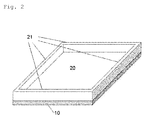
- thermoplastic resin composition (A) that contains a thermoplastic resin and an inorganic filler blended in to raise the crystallization temperature of the thermoplastic resin, but it is desirable to minimize molding shrinkage when designing the shape of components or products, as shall be apparent. For example, as shown in Fig.
- the thickness of the resin member 20 is preferably about 0.5 to 10 mm, and typically the height of the ribs 21 is preferably 1.0 mm or greater, depending on the rate of shrinkage of the resin material. Also, protrusions (bosses), holes, steps, or the like could be furnished instead of the ribs 21.
- the method for contact bonding the thermoplastic resin composition (A) and the metal (B) can be extrusion performed by the usual methods.
- the overall shape is preferably that of a tube or rod having a uniform cross section, such as cylindrical or the like, and having a multilayer configuration of resin and metal.
- the resin and the metal are sufficiently bonded in the composite of the present invention, application is possible for a wide variety of purposes, such as automotive components, electrical/electronic components, general mechanical components, sheets, tape, pipes, tubes, and the like, and the composite is particularly suitable for use in applications in which heat resistance, minimal gas/liquid permeability, dimensional/shape stability, electrical conductivity, heat conductivity, and strength are required concomitantly, such as in automotive fuel components, for example.
- thermoplastic resin composition (A) (Thermoplastic resin composition (A))
- a polyamide resin composition (hereinafter designated as (a-1)) comprising 40 mass% of talc (PKP-80 made by Fuji Talc Industrial Co. Ltd.) having a 14 ⁇ m mean particle size, surface treated with 1 mass% of an aminosilane coupling agent; and 60 mass% of polyamide 6 of 2.47 relative viscosity, and an aqueous extraction fraction of 5 mass% or less.
- PDP-80 made by Fuji Talc Industrial Co. Ltd.
- a polyamide resin composition (a-2) (hereinafter designated as (a-2)) similar to (a-1) except that the blended amount of talc in (a-1) was reduced to 0.5 mass%.
- a polyamide resin composition (a-3) (hereinafter designated as (a-3)) comprising 30 mass% of talc (SIMGON M made by Nippon Talc Co. Ltd.) of 8 ⁇ m mean particle size; and 70 mass% of polyamide 6 of 2.47 relative viscosity, and an aqueous extraction fraction of 5 mass% or less.
- a polyamide resin composition (a-4) (hereinafter designated as (a-4)) comprising 40 volume% of graphite (SP-10 made by Nippon Graphite Industries Co. Ltd.) of 33 ⁇ m mean particle size and bulk density of 0.18 g/cm 3 ; and 60 volume% of polyamide 6 of 2.47 relative viscosity, and an aqueous extraction fraction of 5 mass% or less.
- a polyamide resin composition (a-5) (hereinafter designated as (a-5)) comprising 40 volume% of magnesium oxide (RF-50-AC made by Ube Material Industries Co. Ltd.) of 2.3 ⁇ m mean particle size and bulk density of 0.4 g/cm 3 ; and 60 volume% of polyamide 6 of 2.47 relative viscosity, and an aqueous extraction fraction of 5 mass% or less.
- a polyamide resin composition (a-6) (hereinafter designated as (a-6)) comprising 40 mass% of wollastonite (FPW-400S made by Kinsei Matec Co. Ltd.) of 7-9 ⁇ m mean particle size; and 60 mass% of polyamide 6 of 2.47 relative viscosity, and an aqueous extraction fraction of 5 mass% or less.
- a-6 wollastonite (FPW-400S made by Kinsei Matec Co. Ltd.) of 7-9 ⁇ m mean particle size; and 60 mass% of polyamide 6 of 2.47 relative viscosity, and an aqueous extraction fraction of 5 mass% or less.
- a polyamide resin composition (a-7) (hereinafter designated as (a-7)) comprising 30 mass% of glass fiber (ECSO3T249 made by Nippon Electric Glass Co. Ltd.); and 70 mass% of polyamide 6 of 2.64 relative viscosity, and an aqueous extraction fraction of 5 mass% or less.
- a polyamide resin composition (a-8) (hereinafter designated as (a-8)) comprising 45 mass% of glass fiber (ECSO3T249 made by Nippon Electric Glass Co. Ltd.); and 55 mass% of polyamide 6 of 2.64 relative viscosity, and an aqueous extraction fraction of 5 mass% or less.
- a polyamide resin composition (a-9) (hereinafter designated as (a-9)) comprising 45 mass% of glass fiber (ECSO3T289 made by Nippon Electric Glass Co. Ltd.); and 55 mass% of polyamide 66 of 2.75 relative viscosity, and an aqueous extraction fraction of 5 mass% or less.
- a polyamide resin composition (a-10) (hereinafter designated as (a-10)) comprising 35 mass% of glass fiber (ECSO3T289 made by Nippon Electric Glass Co. Ltd.); 5 mass% of polyamide 12; 13 mass% of aromatic polyamide; and 47 mass% of polyamide 66 of 2.75 relative viscosity, and an aqueous extraction fraction of 5 mass% or less.
- Polyamide 6 resin of 2.47 relative viscosity, an aqueous extraction fraction of 5 mass% or less, and a crystallization temperature Tc of 179.8°C (hereinafter designated as (a-11) ).
- Test pieces of stainless steel, steel material, and aluminum, having exterior dimensions of 12 mm ⁇ 12 mm, thickness of 1.0 mm, and length of 150 mm were prepared.
- Treatment 1 The surfaces of the respective test pieces were subjected to surface treatment employing the erosive liquid (hydrazine) disclosed in Patent Document 1 to form microscopic asperities (hereinafter denoted as Treatment 1), or to surface treatment employing the triazine dithiol derivative disclosed in Patent Document 3 for anchoring to the metal surface (hereinafter denoted as Treatment 2).
- the surface-treated metal was placed in a multilayer pouch of polyethylene and aluminum, sealed with a heat sealing machine, and kept at room temperature until just before bonding molding to the resin.
- the metal member of the composite shown by 1 in Fig. 1 was secured in an N735 vise made by ERON Corp.
- a 200 mm ⁇ 150 mm ⁇ 12 mm sheet of SUS 304 was inserted into the resin member from the opening side, and bending load was applied by the inserted metal plate in a section 0.2 mm away from the hatched section 4 in Fig. 1 , which is the interface of the resin and metal of the composite, to bring about rupture of the composite.
- the bending moment at the time of rupture was divided by the section modulus of the entire bonding face, to derive the bending strength.
- Binding strength Pa 0.2 m ⁇ load at rupture N / 0.15 m ⁇ 0.012 m ⁇ 0.012 m / 6 Bonding was evaluated in terms of the state of the bonding face, in the following five levels A to E.
- a test piece 4 mm wide, 4 mm thick, and 10 mm long was cut from the spool section (5 in Fig. 1 ) obtained during molding of the composite.
- a 2 g load was applied to the cut test piece, and the linear coefficient of expansion was measured in a temperature range of 50 to 150°C, at a rate of temperature increase of 5°C/min, taking the average value thereof as the linear coefficient of expansion of the thermoplastic resin.
- a test piece of thin plate form not exceeding disk dimensions of 6 mm diameter and 1 mm thickness, was taken from the spool section. Measurements were made in a nitrogen atmosphere, employing as the device an EXSTAR 6000 DSC G6220 differential scanning calorimeter made by Seiko Instruments Inc. The test piece was heated from room temperature to 250°C at a rate of 10°C/min, held at 250°C for 10 minutes, then heated to a temperature of 25°C at a rate of 10°C/min. The peak temperature observed in the DSC during temperature decrease was designated as Tc.
- An aluminum test piece surface-treated using Treatment 1 was preheated in an SONW-450 natural convection dryer made by As One Corp., set to 200°C. The test piece was then positioned in a die for forming the composite of Fig. 1 , which was attached to an SE-100D injection molder made by Sumitomo Heavy Industries Co. Ltd.
- a polyamide resin composition of a mixture of 12.5 mass% of (a-1) and 87.5 mass% of (a-6) was introduced into the injection molder, and injected into the die (at a die temperature of 150°C) at a resin temperature of 260°C, and after 40 seconds at a holding pressure of 40 MPa, was cooled in the die for 45 seconds, to obtain a composite of the shape in Fig. 1 .
- Strength measurement and a bonding evaluation were performed on the obtained composite. Measurement of linear coefficient of expansion was performed on a cut test piece. Results are shown in Table 1.
- Example 1 A composite was obtained as in Example 1, except for using 25 mass% of (a-1) and 75 mass% of (a-6) in Example 1. Strength measurement and a bonding evaluation were performed on the obtained composite. Measurement of linear coefficient of expansion was performed on a cut test piece. Results are shown in Table 1.
- Example 1 A composite was obtained as in Example 1, except for using 50 mass% of (a-1) and 50 mass% of (a-6) in Example 1. Strength measurement and a bonding evaluation were performed on the obtained composite. Measurements of linear coefficient of expansion and crystallization temperature were performed on a cut test piece. Results are shown in Table 1.
- Example 1 A composite was obtained as in Example 1, except for using 100 mass% of (a-1), and not using (a-6) in Example 1. Strength measurement and a bonding evaluation were performed on the obtained composite. Measurements of linear coefficient of expansion and crystallization temperature were performed on a cut test piece. Results are shown in Table 1.
- Example 1 A composite was obtained as in Example 1, except for using 100 mass% of (a-6), and not using (a-1) in Example 1. Strength measurement and a bonding evaluation were performed on the obtained composite. Measurements of linear coefficient of expansion and crystallization temperature were performed on a cut test piece. Results are shown in Table 1. [Table 1] Thermoplastic resin Metal Molding conditions Composite Resin Amt. Mass% Filler Amt.
- a steel test piece surface-treated using Treatment 1 was preheated in an SONW-450 natural convection dryer made by As One Corp., set to 200°C. The test piece was then positioned in a die for forming the composite of Fig. 1 , which was attached to an SE-100D injection molder made by Sumitomo Heavy Industries Co. Ltd.
- a polyamide resin composition of a mixture of 2 mass% of (a-2), 66.7 mass% of (a-7), and 31.3 mass% of (a-11) was introduced into the injection molder, and injected into the die (at a die temperature of 150°C) at a resin temperature of 270°C, and after 45 seconds at a holding pressure of 50 MPa, was cooled in the die for 45 seconds, to obtain a composite of the shape in Fig. 1 .
- Strength measurement and a bonding evaluation were performed on the obtained composite. Measurements of linear coefficient of expansion and crystallization temperature were performed on a cut test piece. Results are shown in Table 2.
- a composite was obtained as in Example 5, except for using 20 mass% of (a-2), 66.7 mass% of (a-7), and 13.3 mass% of (a-11) in Example 5.
- Strength measurement and a bonding evaluation were performed on the obtained composite. Measurements of linear coefficient of expansion and crystallization temperature were performed on a cut test piece. Results are shown in Table 2.
- a composite was obtained as in Example 5, except for using 2.5 mass% of (a-1), 66.7 mass% of (a-7), and 30.8 mass% of (a-11) in Example 5.
- Strength measurement and a bonding evaluation were performed on the obtained composite. Measurements of linear coefficient of expansion and crystallization temperature were performed on a cut test piece. Results are shown in Table 2.
- a composite was obtained as in Example 5, except for using 25 mass% of (a-1), 66.7 mass% of (a-7), and 8.3 mass% of (a-11) in Example 5.
- Strength measurement and a bonding evaluation were performed on the obtained composite. Measurements of linear coefficient of expansion and crystallization temperature were performed on a cut test piece. Results are shown in Table 2.
- Example 5 A composite was obtained as in Example 5, except for using 50 mass% of (a-1), 44.4 mass% of (a-8), and 5.6 mass% of (a-11) in Example 5. Strength measurement and a bonding evaluation were performed on the obtained composite. Measurements of linear coefficient of expansion and crystallization temperature were performed on a cut test piece. Results are shown in Table 2.
- Example 5 A composite was obtained as in Example 5, except for using 66.7 mass% of (a-7) and 33.3 mass% of (a-11) in Example 5. Strength measurement and a bonding evaluation were performed on the obtained composite. Measurements of linear coefficient of expansion and crystallization temperature were performed on a cut test piece. Results are shown in Table 2. [Table 2] Thermoplastic resin Metal Molding conditions Composite Resin Amt. Mass% Filler Amt.
- a stainless steel test piece surface-treated using Treatment 1 was preheated in an SONW-450 natural convection dryer made by As One Corp., set to 200°C.
- the test piece was then positioned in a die for forming the composite of Fig. 1 , which was attached to an SE-100D injection molder made by Sumitomo Heavy Industries Co. Ltd. (a-1) was introduced into the injection molder, and injected into the die (at a die temperature of 140°C) at a resin temperature of 270°C, and after 15 seconds at a holding pressure of 60 MPa, was cooled in the die for 30 seconds, to obtain a composite of the shape in Fig. 1 .
- Strength measurement and a bonding evaluation were performed on the obtained composite. Measurements of linear coefficient of expansion and crystallization temperature were performed on a cut test piece. Results are shown in Table 3.
- Example 10 A composite was obtained as in Example 10, except that the test piece was a steel material surface-treated using Treatment 1, rather than the stainless steel test piece surface-treated using Treatment 1 in Example 10. Strength measurement and a bonding evaluation were performed on the obtained composite. Measurements of linear coefficient of expansion and crystallization temperature were performed on a cut test piece. Results are shown in Table 3.
- Example 10 A composite was obtained as in Example 10, except that the test piece was aluminum surface-treated using Treatment 1, rather than the stainless steel test piece surface-treated using Treatment 1 in Example 10. Strength measurement and a bonding evaluation were performed on the obtained composite. Measurements of linear coefficient of expansion and crystallization temperature were performed on a cut test piece. Results are shown in Table 3.
- Example 10 A composite was obtained as in Example 10, except that the test piece was stainless steel surface-treated using Treatment 2, rather than the stainless steel test piece surface-treated using Treatment 1 in Example 10. Strength measurement and a bonding evaluation were performed on the obtained composite. Measurements of linear coefficient of expansion and crystallization temperature were performed on a cut test piece. Results are shown in Table 3.
- Example 10 A composite was obtained as in Example 10, except that the test piece was a steel material surface-treated using Treatment 2, rather than the stainless steel test piece surface-treated using Treatment 2 in Example 13. Strength measurement and a bonding evaluation were performed on the obtained composite. Measurements of linear coefficient of expansion and crystallization temperature were performed on a cut test piece. Results are shown in Table 3.
- Example 10 A composite was obtained as in Example 10, except that the test piece was aluminum surface-treated using Treatment 2, rather than the stainless steel test piece surface-treated using Treatment 2 in Example 13. Strength measurement and a bonding evaluation were performed on the obtained composite. Measurements of linear coefficient of expansion and crystallization temperature were performed on a cut test piece. Results are shown in Table 3.
- a stainless steel test piece surface-treated using Treatment 1 was preheated in an SONW-450 natural convection dryer made by As One Corp., set to 200°C.
- the test piece was then positioned in a die for forming the composite of Fig. 1 , which was attached to an SE-100D injection molder made by Sumitomo Heavy Industries Co. Ltd. (a-3) was introduced into the injection molder, and injected into the die (at a die temperature of 140°C) at a resin temperature of 270°C, and after 15 seconds at a holding pressure of 60 MPa, was cooled in the die for 30 seconds, to obtain a composite of the shape in Fig. 1 .
- Strength measurement and a bonding evaluation were performed on the obtained composite. Measurements of linear coefficient of expansion and crystallization temperature were performed on a cut test piece. Results are shown in Table 3.
- Example 16 A composite was obtained as in Example 16, except that the test piece was a steel material surface-treated using Treatment 1, rather than the stainless steel test piece surface-treated using Treatment 1 in Example 16. Strength measurement and a bonding evaluation were performed on the obtained composite. Measurements of linear coefficient of expansion and crystallization temperature were performed on a cut test piece. Results are shown in Table 3.
- Example 16 A composite was obtained as in Example 16, except that the test piece was aluminum surface-treated using Treatment 1, rather than the stainless steel test piece surface-treated using Treatment 1 in Example 16. Strength measurement and a bonding evaluation were performed on the obtained composite. Measurements of linear coefficient of expansion and crystallization temperature were performed on a cut test piece. Results are shown in Table 3.
- Example 16 A composite was obtained as in Example 16, except that the test piece was stainless steel surface-treated using Treatment 2, rather than the stainless steel test piece surface-treated using Treatment 1 in Example 16. Strength measurement and a bonding evaluation were performed on the obtained composite. Measurements of linear coefficient of expansion and crystallization temperature were performed on a cut test piece. Results are shown in Table 3.
- Example 19 A composite was obtained as in Example 19, except that the test piece was a steel material surface-treated using Treatment 2, rather than the stainless steel test piece surface-treated using Treatment 2 in Example 19. Strength measurement and a bonding evaluation were performed on the obtained composite. Measurements of linear coefficient of expansion and crystallization temperature were performed on a cut test piece. Results are shown in Table 3.
- Example 19 A composite was obtained as in Example 19, except that the test piece was aluminum surface-treated using Treatment 2, rather than the stainless steel test piece surface-treated using Treatment 2 in Example 19. Strength measurement and a bonding evaluation were performed on the obtained composite. Measurements of linear coefficient of expansion and crystallization temperature were performed on a cut test piece. Results are shown in Table 3.
- Example 10 A composite was obtained as in Example 10, except that the resin composition in Example 10 was replaced with a mixture of 50 mass% of (a-1) and 50 mass% of (a-9), and the die temperature was changed to 120°C. Strength measurement and a bonding evaluation were performed on the obtained composite. Measurement of linear coefficient of expansion was performed on a cut test piece. Results are shown in Table 3.
- Example 22 A composite was obtained as in Example 22, except that the resin composition in Example 22 was replaced with (a-4), and the type of metal was changed to aluminum, and a bonding evaluation was performed. Measurements of linear coefficient of expansion and crystallization temperature were performed on a cut test piece. Results are shown in Table 3.
- a composite was obtained as in Example 23, except that the graphite of the resin composition in Example 23 was replaced with magnesium oxide, and the resin composition in Example 22 was replaced with (a-5), and a bonding evaluation was performed. Measurements of linear coefficient of expansion and crystallization temperature were performed on a cut test piece. Results are shown in Table 3.
- a stainless steel test piece surface-treated using Treatment 1 was preheated in an SONW-450 natural convection dryer made by As One Corp., set to 180°C.
- the test piece was then positioned in a die for forming the composite of Fig. 1 , which was attached to an SE-100D injection molder made by Sumitomo Heavy Industries Co. Ltd. (a-7) was introduced into the injection molder, and injected into the die (at a die temperature of 80°C) at a resin temperature of 290°C, and after 15 seconds at a holding pressure of 60 MPa, was cooled in the die for 30 seconds, to obtain a composite of the shape in Fig. 1 .
- Strength measurement and a bonding evaluation were performed on the obtained composite. Measurements of linear coefficient of expansion and crystallization temperature were performed on a cut test piece. Results are shown in Table 3.
- a composite was obtained as in Comparative Example 3, except that the test piece was a steel material surface-treated using Treatment 1, rather than the stainless steel test piece surface-treated using Treatment 1 in Comparative Example 3.
- Strength measurement and a bonding evaluation were performed on the obtained composite. Measurements of linear coefficient of expansion and crystallization temperature were performed on a cut test piece. Results are shown in Table 3.
- a composite was obtained as in Comparative Example 3, except that the test piece was aluminum surface-treated using Treatment 1, rather than the stainless steel test piece surface-treated using Treatment 1 in Comparative Example 3.
- Strength measurement and a bonding evaluation were performed on the obtained composite. Measurements of linear coefficient of expansion and crystallization temperature were performed on a cut test piece. Results are shown in Table 3.
- a composite was obtained as in Comparative Example 3, except that the test piece was stainless steel surface-treated using Treatment 2, rather than the stainless steel test piece surface-treated using Treatment 1 in Comparative Example 3.
- Strength measurement and a bonding evaluation were performed on the obtained composite. Measurements of linear coefficient of expansion and crystallization temperature were performed on a cut test piece. Results are shown in Table 3.
- a composite was obtained as in Comparative Example 6, except that the test piece was a steel material surface-treated using Treatment 2, rather than the stainless steel test piece surface-treated using Treatment 2 in Comparative Example 6.
- Strength measurement and a bonding evaluation were performed on the obtained composite. Measurements of linear coefficient of expansion and crystallization temperature were performed on a cut test piece. Results are shown in Table 3.
- a composite was obtained as in Comparative Example 6, except that the test piece was aluminum surface-treated using Treatment 2, rather than the stainless steel test piece surface-treated using Treatment 2 in Comparative Example 6.
- Strength measurement and a bonding evaluation were performed on the obtained composite. Measurements of linear coefficient of expansion and crystallization temperature were performed on a cut test piece. Results are shown in Table 3.
- a composite was obtained as in Comparative Example 3, except that the test piece was preheated at 200°C, and the die temperature was changed to 150°C, in Comparative Example 3.
- Strength measurement and a bonding evaluation were performed on the obtained composite. Measurements of linear coefficient of expansion and crystallization temperature were performed on a cut test piece. Results are shown in Table 3.
- a composite was obtained as in Comparative Example 9, except that the test piece was stainless steel surface-treated using Treatment 2, rather than the stainless steel test piece surface-treated using Treatment 1 in Comparative Example 9.
- Strength measurement and a bonding evaluation were performed on the obtained composite. Measurements of linear coefficient of expansion and crystallization temperature were performed on a cut test piece. Results are shown in Table 3.
- a composite was obtained as in Comparative Example 9, except for substituting (a-9) for (a-7) in Comparative Example 9.
- Strength measurement and a bonding evaluation were performed on the obtained composite. Measurements of linear coefficient of expansion and crystallization temperature were performed on a cut test piece. Results are shown in Table 3.
- a composite was obtained as in Comparative Example 11 except that the test piece was a steel material surface-treated using Treatment 1, rather than the stainless steel test piece surface-treated using Treatment 1 in Comparative Example 11. Strength measurement and a bonding evaluation were performed on the obtained composite. Measurements of linear coefficient of expansion and crystallization temperature were performed on a cut test piece. Results are shown in Table 3.
- a composite was obtained as in Comparative Example 11 except that the test piece was aluminum surface-treated using Treatment 1, rather than the stainless steel test piece surface-treated using Treatment 1 in Comparative Example 11.
- Strength measurement and a bonding evaluation were performed on the obtained composite. Measurements of linear coefficient of expansion and crystallization temperature were performed on a cut test piece. Results are shown in Table 3.
- a composite was obtained as in Comparative Example 9, except for substituting (a-6) for (a-9) in Comparative Example 9.
- Strength measurement and a bonding evaluation were performed on the obtained composite. Measurements of linear coefficient of expansion and crystallization temperature were performed on a cut test piece. Results are shown in Table 3.
- a composite was obtained as in Comparative Example 11, except that the test piece was stainless steel surface-treated using Treatment 2, rather than the stainless steel test piece surface-treated using Treatment 1 in Comparative Example 14. Strength measurement and a bonding evaluation were performed on the obtained composite. Measurements of linear coefficient of expansion and crystallization temperature were performed on a cut test piece. Results are shown in Table 3.
- a stainless steel test piece surface-treated using Treatment 1 was preheated in an SONW-450 natural convection dryer made by As One Corp., set to 200°C.
- the test piece was then positioned in a die for forming the composite of Fig. 1 , which was attached to an SE-100D injection molder made by Sumitomo Heavy Industries Co. Ltd. (a-10) was introduced into the injection molder, and injected into the die (at a die temperature of 80°C) at a resin temperature of 290°C, and after 15 seconds at a holding pressure of 60 MPa, was cooled in the die for 30 seconds, to obtain a composite of the shape in Fig. 1 .
- Strength measurement and a bonding evaluation were performed on the obtained composite. Results are shown in Table 3.
- a composite was obtained as in Comparative Example 16, except that the test piece was stainless steel surface-treated using Treatment 2, rather than the stainless steel test piece surface-treated using Treatment 1 in Comparative Example 16. Strength measurement and a bonding evaluation were performed on the obtained composite. Results are shown in Table 3.
- a composite was obtained as in Comparative Example 16, except for substituting (a-8) for (a-10) in Comparative Example 16.
- Strength measurement and a bonding evaluation were performed on the obtained composite. Measurements of linear coefficient of expansion and crystallization temperature were performed on a cut test piece. Results are shown in Table 3.
- a composite was obtained as in Comparative Example 18 except that the test piece was a steel material surface-treated using Treatment 1, rather than the stainless steel test piece surface-treated using Treatment 1 in Comparative Example 18.
- Strength measurement and a bonding evaluation were performed on the obtained composite. Measurements of linear coefficient of expansion and crystallization temperature were performed on a cut test piece. Results are shown in Table 3.
- a composite was obtained as in Comparative Example 18 except that the test piece was aluminum surface-treated using Treatment 1, rather than the stainless steel test piece surface-treated using Treatment 1 in Comparative Example 18.
- Strength measurement and a bonding evaluation were performed on the obtained composite. Measurements of linear coefficient of expansion and crystallization temperature were performed on a cut test piece. Results are shown in Table 3. [Table 3] Thermoplastic resin Metal Molding conditions Composite Resin Amt. Mass% Filler Amt.
Landscapes
- Engineering & Computer Science (AREA)
- Mechanical Engineering (AREA)
- Manufacturing & Machinery (AREA)
- Laminated Bodies (AREA)
- Injection Moulding Of Plastics Or The Like (AREA)
- Compositions Of Macromolecular Compounds (AREA)
Abstract
Description
- The present invention relates to a composite of metal and thermoplastic resin.
- In a wide range of fields, such as automotive, electrical/electronic, and the like, engineering plastics, in which constituent materials of components that had previously been made of metal materials are replaced by resin materials, have contributed to lighter weight and lower cost of the components. However, with components in which resin materials are used alone as the constituent material, replacement with resin materials is reaching a limit, for reasons having to do with insufficient strength and rigidity at high temperatures, inadequate resistance to specific chemical substances, and the like. Moreover, it has been attempted to improve surface texture, corrosion preventive function, and the like in components made of metal materials alone, through compositing or through multi-layering with resin materials, but due to poor bonding of metal and resin, there are cases of deficient strength of the component as a whole, or, in cases of components that come into contact with liquids, of diminished functionality of the component due to infiltration or accumulation of liquid in the joined portions of the metal and the resin.
- Given these circumstances, there exists a need for a technique for secure bonding of metals and resins, and a number of methods have been proposed. As one typical example, a metal surface is subjected primarily to chemical treatment to form microscopic asperities, into which a resin is flowed and solidified, to bond the metal and the resin together. Patent Document 1 discloses a procedure for forming microscopic asperities on a metal surface by a method of immersing the metal in an aqueous solution of one or more compounds selected from ammonia, hydrazine, and water-soluble amines.
Patent Document 2 discloses a procedure for forming microscopic asperities on a metal surface by an anodic oxidation method. Meanwhile,Patent Document 3 discloses a method for anchoring a specific compound to a metal surface, the method involving bringing a melted resin into contact with the metal to which the specific compound has been linked, to bring about bonding of the two. - Further, techniques employing specific resins on metals having undergone specific treatments, in order to improve adhesion between the resin and the metal, have been proposed. For example,
Patent Document 4 discloses a technique for preparation of an aluminum alloy having microscopic openings by an anodic oxidation method, to which polyphenylene sulfide into which an olefin resin has been blended is bonded, to improve the bonding strength.Patent Document 5 discloses a technique for bonding a polyamide resin to an aluminum alloy having undergone surface treatment with an erosive aqueous solution, and discloses that, in this case, the bonding state can be further improved by blending an aromatic polyamide or impact resistance improver to the polyamide resin. -
- [Patent Document 1] Japanese Patent No.
3967104 - [Patent Document 2] Japanese Patent No.
4541153 - [Patent Document 3] Japanese Laid-Open Patent Application No.
5-51671 - [Patent Document 4] Japanese Patent No.
4527196 - [Patent Document 5] Japanese Laid-Open Patent Application No.
2007-182071 - However, none of these techniques for bonding resin and metal is highly practical: in the case, for example, of that disclosed in Patent Document 1, in which microscopic asperities are formed on a metal surface, and a molten resin is flowed and solidified therein, when typical thermoplastic resins such as polyamide 6 or polyamide 66 are employed, a state of secure bonding could not be obtained, as shown in the comparative examples given below. Moreover, while
Patent Documents - It is an object of the present invention to offer a composite in which a thermoplastic resin and a metal are securely bonded, without any loss of characteristics of the thermoplastic resin.
- The aforementioned object is solved by the present invention shown below.
- Specifically, the present invention provides a composite obtained by contact bonding of thermoplastic resin composition (A) and a metal (B), wherein in the composite,
the thermoplastic resin composition is a composition containing a thermoplastic resin and an inorganic filler for raising the crystallization temperature of the thermoplastic resin by 3°C or more, and the metal (B) is a surface-treated metal. - In the present invention, the thermoplastic resin is preferably a polyamide resin.
- The inorganic filler is preferably at least one selected from the group consisting of talc, graphite, magnesium oxide, kaolin, and calcium carbonate.
- The inorganic filler is preferably at least one selected from the group consisting of talc, graphite, and magnesium oxide.
- The blending amount of the inorganic filler in the thermoplastic resin composition (A) is preferably from 0.01 mass% to 50 mass%.
- The surface treatment of the metal (B) is preferably a treatment for forming microscopic asperities on, or anchoring a chemical substance to, the surface thereof.
- The composite of the present invention is preferably one obtained by contact bonding through injection molding of the thermoplastic resin composition (A) and the metal (B).
- Further, one shrinkage-inhibiting structure selected from the group consisting of a rib, protrusion, hole, and step is provided to a surface of the thermoplastic resin composition (A) facing the bonding surface of the thermoplastic resin composition (A) and the metal (B).
- Further, the composite of the present invention may have an overall shape of tube or rod shape, with the resin and metal having a multilayer structure.
- The composite of the present invention affords sufficient bonding of resin and metal, with no loss of the high-temperature characteristics, chemical resistance, and so on of the thermoplastic resin, and therefore has a high structural-reinforcing effect on the metal, making it suitable for use in structural components in a wide range of fields, such as the automotive field, electrical/electronic field, general industrial machinery field, and the like. Moreover, when a metal is introduced into a resin for purposes of localized improvement of dimensional accuracy, heat resistance, and the like, according to the present invention, the anchoring state of the metal and resin may be markedly improved, further improving the quality as a composite. Similarly, in sheets, tapes, pipes, tubes, and the like, of resin and metal in a multilayer arrangement in order to increase conductivity or gas permeation-inhibiting functionality, the quality thereof can be further improved by employing the composite of the present invention.
- Moreover, the composite of the present invention is effective both in techniques involving flowing and solidifying resin into microscopic asperities on a metal surface, and in techniques involving anchoring a compound to a metal surface, and bonding a resin thereto. Consequently, through the present invention, it is possible to accomplish bonding through injection molding of a thermoplastic resin onto a metal having a compound anchored to the metal surface, which had not been possible previously, whereby a composite obtained by contact bonding of a thermoplastic resin and a metal having a compound anchored to the metal surface can be manufactured.
-
-
FIG. 1 is a perspective view showing an embodiment of the composite of the present invention. -
FIG. 2 is a perspective view showing another embodiment of the composite of the present invention. - The present invention provides a composite obtained by contact bonding of a thermoplastic resin (A) and a metal (B). The thermoplastic resin (A), the metal (B), and modes of contact bonding thereof are described below.
- The thermoplastic resin (A) employed in the present invention is a composition containing a thermoplastic resin and an inorganic filler for raising the crystallization temperature of the thermoplastic resin by 3°C or more.
- While there are no particular limitations as to the thermoplastic resin used in the thermoplastic resin composition (A), high density polyethylene (HDPE), medium density polyethylene (MDPE), low density polyethylene (LDPE), linear low density polyethylene (LLDPE), ultra high molecular weight polyethylene (UHMWPE), polypropylene (PP), ethylene/propylene copolymer (EPR), ethylene/butene copolymer (EBR), ethylene/vinyl acetate copolymer (EVA), ethylene/acrylic acid copolymer (EAA), ethylene/methacrylic acid copolymer (EMAA), ethylene/methyl acrylate copolymer (EMA), ethylene/methyl methacrylate copolymer (EMMA), ethylene/ethyl acrylate copolymer (EEA), and other such polyolefin resins; the aforementioned polyolefin resins modified by compounds containing functional groups such as acrylic acid, methacrylic acid, maleic acid, fumaric acid, itaconic acid, crotonic acid, mesaconic acid, citraconic acid, glutaconic acid, cis-4-cyclohexene-1,2-dicarboxylic acid, endobicyclo-[2.2.1]-5-heptene-2,3-dicarboxylic acid, and other such carboxyl groups and metal salts (Na, Zn, K, Ca, Mg) thereof, maleic anhydride, itaconic anhydride, citraconic anhydride, endobicyclo-[2.2.1]-5-heptene-2,3-dicarboxylic anhydride, and other acid anhydride groups, or glycidyl acrylate, glycidyl methacrylate, glycidyl ethacrylate, glycidyl itaconate, glycidyl citraconate, and other such epoxy groups; polybutylene terephthalate (PBT), polyethylene terephthalate (PET), polytrimethylene terephthalate (PTT), polyethylene isophthalate (PEI), PET/PEI copolymer, polyarylate (PAR), polybutylene naphthalate (PBN), polyethylene naphthalate (PEN), liquid crystal polyester (LCP), polylactic acid (PLA), polyglycolic acid (PGA), and other such polyester resins; polyacetal (POM), polyphenylene oxide (PPO), and other polyether resins; polysulfone (PSF), polyether sulfone (PES), and other such polysulfone resins; polyphenylene sulfide resin (PPS), polythioether sulfone resin (PTES), and other such polythioether resins; polyether ether ketone (PEEK), polyallyl ether ketone (PAEK), and other such polyketone resins; polyacrylonitrile (PAN), polymethacrylonitrile, acrylonitrile/styrene copolymer (AS), methacrylonitrile/styrene copolymer, acrylonitrile/butadiene/styrene copolymer (ABS), methacrylonitrile/styrene/butadiene copolymer (MBS), and other such polynitrile resins; polymethyl methacrylate (PMMA), polyethyl methacrylate (PEMA), and other such polymethacrylate resins; polyvinyl acetate (PVAc) and other such polyvinyl ester resins; polyvinylidene chloride (PVDC), polyvinyl chloride (PVC), vinyl chloride/vinylidene chloride copolymer, vinylidene chloride/methyl acrylate copolymer, and other such polyvinyl resins; cellulose acetate, cellulose butyrate, and other such cellulose resins; polycarbonate (PC) and other such polycarbonate resins; thermoplastic polyimide (PI), polyamide imide (PAI), polyether imide, and other such polyimide resins; polyvinylidene fluoride (PVDF), polyvinyl fluoride (PVF), ethylene/tetrafluoroethylene copolymer (ETFE), polychlorotrifluoroethylene (PCTFE), ethylene/chlorotrifluoroethylene copolymer (ECTFE), tetrafluoroethylene/hexafluoropropylene copolymer (TFE/HFP, FEP), tetrafluoroethylene/hexafluoropropylene/vinylidene fluoride copolymer (TFE/HFP/VDF, THV), tetrafluoroethylene/perfluoro(alkyl vinyl ether) copolymer (PFA), and other such fluororesins; thermoplastic polyurethane resins, polyurethane elastomers, and polyamide elastomers or polyester elastomers apart from those specified in the present invention, and the like, may be cited. Of these, apart from polybutylene terephthalate (PBT) and polyphenylene sulfide resin (PPS), which have weak bonding strength to surface-treated metal, thermoplastic resins that exhibit relative distinct crystallization or solidification temperatures are preferred from the standpoint of improving the bonding effect to metal. Polyamide resins are more preferred, due to ease of handling during molding and the like, high heat resistance, and mechanical strength. These may be used singly, or two or more types used together.
- As polyamide resins, there may be cited, for example, polycaprolactam (polyamide 6), polyundecalactam (polyamide 11), polydodecalactam (polyamide 12), polyethylene adipamide (polyamide 26), polytetramethylene adipamide (polyamide 46), polyhexamethylene adipamide (polyamide 66), polyhexamethylene azelamide (polyamide 69), polyhexamethylene sebacamide (polyamide 610), polyhexamethylene undecamide (polyamide 611), polyhexamethylene dodecamide (polyamide 612), polyhexamethylene terephthalamide (polyamide 6T), polyhexamethylene isophthalamide (polyamide 6I) , polyhexamethylene hexahydroterephthalamide (polyamide 6T(H)), polynonamethylene adipamide (polyamide 96), polynonamethylene azelamide (polyamide 99), polynonamethylene sebacamide (polyamide 910), polynonamethylene dodecamide (polyamide 912), polynonamethylene terephthalamide (polyamide 9T), polytrimethylhexamethylene terephthalamide (polyamide TMHT), polynonamethylene hexahydroterephthalamide (polyamide 9T(H)), polynonamethylene naphthalamide (polyamide 9N), polydecamethylene adipamide (polyamide 106), polydecamethylene azelamide (polyamide 109), polydecamethylene decamide (polyamide 1010), polydecamethylene dodecamide (polyamide 1012), polydecamethylene terephthalamide (polyamide 10T), polydecamethylene hexahydroterephthalamide (polyamide 10T(H)), polydecamethylene naphthalamide (polyamide 10N), polydodecamethylene adipamide (polyamide 126), polydodecamethylene azelamide (polyamide 129), polydodecamethylene sebacamide (polyamide 1210), polydodecamethylene dodecamide (polyamide 1212), polydodecamethylene terephthalamide (polyamide 12T), polydodecamethylene hexahydroterephthalamide (polyamide 12T(H)), polydodecamethylene naphthalamide (polyamide 12N), polymetaxylylene adipamide (polyamide MXD6), polymetaxylylene suberamide (polyamide MXD8), polymetaxylylene azelamide (polyamide MXD9), polymetaxylylene sebacamide (polyamide MXD10), polymetaxylylene dodecamide (polyamide MXD12), polymetaxylylene terephthalamide (polyamide MXDT), polymetaxylylene isophthalamide (polyamide MXDI), polymetaxylylene naphthalamide (polyamide MXDN), polybis(4-aminocyclohexyl)methane dodecamide (polyamide PACM12), polybis(4-aminocyclohexyl)methane terephthalamide (polyamide PACMT), polybis(4-aminocyclohexyl)methane isophthalamide (polyamide PACMI), polybis(3-methyl-4-aminocyclohexyl)methane dodecamide (polyamide dimethyl PACM12), polyisophorone adipamide (polyamide IPD6), polyisophorone terephthalamide (polyamide IPDT), and polyamide copolymers of these. Of these, from the standpoint of a balance between material functionality, such as mechanical characteristics and chemical resistance, on the one hand, and price on the other, polyamide 6, polyamide 12, polyamide 66, polyamide 6/66 copolymer (copolymer of polyamide 6 and polyamide 66; copolymers are denoted in the same fashion hereinbelow), polyamide 6/12 copolymer, or polyamide 6/66/12 copolymer is preferred, with polyamide 6, polyamide 66, polyamide 6/66 copolymer, or polyamide 6/12 copolymer being more preferred, and polyamide 6 and/or polyamide 66 being especially preferred, from the standpoint of moldability, mechanical qualities, and durability. These may be used singly, or two or more types used together.
- There are no particular limitations as to the type of terminal groups of the polyamide resin, or the concentration or molecular weight distribution thereof. In order to adjust the molecular weight, or stabilize melting during the molding process, one, or two or more, molecular weight adjusters selected from acetic acid, stearic acid, or other monocarboxylic acids, meta-xylylene diamine, isophorone diamine, and other such diamines, monoamines, or dicarboxylic acids may be added, as appropriate.
- When measured according to the viscosity measurement method of JIS K-6920 in 96 mass% sulfuric acid, at a polymer concentration of 1 mass%, at a temperature of 25°C, the relative viscosity of the polyamide resin is preferably from 1.0 to 5.0, more preferably from 1.5 to 4.5, and still preferably from 1.8 to 4.0, from the standpoint of the mechanical qualities and moldability of the polyamide resin obtained.
- There is no particular limitation as to the amount of aqueous extraction of the polyamide resin, as measured in accordance with the method for measuring the low-molecular weight content specified in JIS K-6920, but it is preferably 5 mass% or less, due to the possibility of giving rise to environmental problems, such as gases and the like generated during the molding process, to reduced productivity due to deposition on manufacturing equipment, or to poor appearance due to deposition on the composite.
- The inorganic filler for raising by 3°C or more the crystallization temperature of the thermoplastic resin employed in the thermoplastic resin composition (A) may be any inorganic filler that raises the crystallization temperature of the thermoplastic resin by 3°C or more, but from the standpoint of the bonding strength of the composite, an inorganic filler that raises the crystallization temperature of the thermoplastic resin by 6°C or more is preferred.
- As specific inorganic fillers that raise the crystallization temperature of the thermoplastic resin by 3°C or more, at least one selected from the group consisting of talc, graphite, magnesium oxide, kaolin, and calcium carbonate is preferred, and at least one selected from the group consisting of talc, graphite, and magnesium oxide being more preferred.
- The compounding amount of the inorganic filler is preferably 0.01 mass% to 50 mass% of the thermoplastic resin composition (A), and from the standpoint of bonding strength is preferably 0.05 mass% to 20 mass%, more preferably 5 mass% to 20 mass%. Depending on the type of thermoplastic resin, the type of metal, and the surface treatment method thereof, a state of adequate bonding may be obtained even at 0.05 mass%, and it is therefore desirable to select the compounding amount in a manner dependent on the application of the composite.
- There are no particular limitations as to the mean particle size of the inorganic filler, but in consideration of the appearance and impact strength of the molded article, 20 µm or smaller is preferable, while from the standpoint of bonding to metal, 3 to 15 µm is preferred. The mean particle size is measured by sampling the inorganic filler in accordance with, for example, Powder mass mixtures - general rules for methods of sampling (JIS M8100) specified in Japanese Industrial Standards; preparing the inorganic filler as a sample for measurement in accordance with General rules for sample preparation for particle size analysis of fine ceramic raw powders (JIS R1622-1995); and measuring in accordance with Determination of particle size distribution of fine ceramic raw powders by laser diffraction method (JIS R 1629-1997). A SALD-7000 laser diffraction type particle size distribution measurement device, made by Shimadzu Corp., or the like, can be used as the device.
- The inorganic filler may be subjected to a coupling treatment in order to improve cohesion to the resin, to thereby enhance the mechanical properties and molded appearance. As coupling agents, silane coupling agents, epoxy silane coupling agents, and the like may be cited. The added amount for treatment can be from 0.01 to 5 mass parts per 100 mass parts of the inorganic filler.
- In addition to the inorganic filler, the thermoplastic resin composition (A) may contain customarily compounded additives, modifiers, and reinforcing materials of various types, in amounts such that the characteristics of the present invention are not diminished, for example, thermal stabilizers, antioxidants, UV absorbers, weathering agents, fillers, plasticizers, blowing agents, anti-blocking agents, tackifying agents, sealing improvers, antifogging agents, release agents, crosslinking agents, blowing agents, flame retardants, coloring agents (pigments, dyes, and the like), coupling agents, inorganic reinforcing materials such as glass fibers, and the like. There are no particular limitations as to the method for compounding various additives into the thermoplastic resin, and there may be cited typical methods such as dry-blending methods employing a tumbler or mixer; incorporation through melt-kneading in advance at the concentration to be used during molding, employing a single-screw or twin-screw extruder; a masterbatch method involving incorporation into the starting material in advance at high concentration, employing a single-screw or twin-screw extruder, followed by dilution for use at the time of molding, or the like.
- There are no particular limitations as to the metal qualities of the metal (B) of the present invention, provided that the metal is surface-treated. For example, iron, copper, nickel, gold, silver, platinum, cobalt, zinc, lead, tin, titanium, chromium, aluminum, magnesium, manganese, and alloys thereof (stainless steel, brass, phosphor bronze, and the like) can be cited. Metals having a thin film or coating of metal (metal plating, a deposited film, a coating film, or the like) may be targeted as well.
- Surface treatment refers, for example, to treatment by immersion of the metal surface in an erosive liquid or to anodic oxidation, to bring about a state in which microscopic asperities are produced on the metal surface, or a state in which a chemical substance is anchored to the metal surface.
- Water soluble amine compounds can be cited as erosive liquids, and as water soluble amine compounds, there may be cited ammonia, hydrazine, methylamine, dimethylamine, trimethylamine, ethylamine, diethylamine, triethylamine, ethylenediamine, ethanolamine, allylamine, ethanolamine, diethanolamine, triethanolamine, aniline, and other amines. Of these, hydrazine is particularly preferred, due to its minimal odor and effectiveness at low concentration.
- An anodic oxidation film refers to an oxidation film produced on a metal surface when electrical current passes through the metal used as an anode, in an electrolyte solution. The aforementioned water soluble amine compounds may be cited as electrolytes, for example.
- The state in which microscopic asperities are produced on the metal surface is preferably one in which the metal surface, when measured by observation with an electron microscope, is covered by microscopic recesses or hole openings of number-average diameter of 10 to 100 nm.
- Triazine dithiol derivatives may be cited as chemical substances for anchoring to the metal surface. The triazine dithiol derivative is preferably one represented by the following general formula.

- (Preferably, in the formula, R is -OR1, -OOR1, -SmR1, - NR1(R2); R1 and R2 are H, a hydroxyl group, a carbonyl group, an ether group, an ester group, an amide group, an amino group, a phenyl group, a cycloalkyl group, an alkyl group, or a substituent group including an unsaturated group such as an alkyne or alkane, m is an integer from 1 to 8, and M is H, or Na, Li, K, Ba, Ca, an ammonium salt, or other alkali).
- As specific examples of triazine dithiol derivatives of the aforementioned general formula, there may be cited 1,3,5-triazine-2,4,6-trithiol, 1,3,5-triazine-2,4,6-trithiol monosodium, 1,3,5-triazine-2,4,6-trithiol triethanolamine, 6-anilino-1,3,5-triazine-2,4-dithiol, 6-anilino-1,3,5-triazine-2,4-dithiol monosodium, 6-dibutylamino-1,3,5-triazine-2,4-dithiol, 6-dibutylamino-1,3,5-triazine-2,4-dithiol monosodium, 6-diallylamino-1,3,5-triazine-2,4-dithiol, 6-diallylamino-1,3,5-triazine-2,4-dithiol monosodium, 1,3,5-triazine-2,4,6-trithiol ditetrabutylammonium salt, 6-dibutylamino-1,3,5-triazine-2,4-dithiol tetrabutylammonium salt, 6-dioctylamino-1,3,5-triazine-2,4-dithiol, 6-dioctylamino-1,3,5-triazine-2,4-dithiol monosodium, 6-dilaurylamino-1,3,5-triazine-2,4-dithiol, 6-dilaurylamino-1,3,5-triazine-2,4-dithiol monosodium, 6-stearylamino-1,3,5-triazine-2,4-dithiol, 6-stearylamino-1,3,5-triazine-2,4-dithiol monopotassium, 6-oleylamino-1,3,5-triazine-2,4-dithiol, and 6-oleylamino-1,3,5-triazine-2,4-dithiol monopotassium.
- As the method for anchoring the chemical substance on a metal surface, there can be cited a method employing an aqueous solution of the chemical substance, or a solution thereof in a medium of an organic solvent, such as methyl alcohol, isopropyl alcohol, ethyl alcohol, acetone, toluene, ethyl cellosolve, dimethyl formaldehyde, tetrahydrofuran, methyl ethyl ketone, benzene, acetic acid ethyl ether, or the like, in which the metal is deployed as the anode, and a platinum plate, titanium plate, or carbon plate as the cathode, passing a 0.1 mA/dm2-10 A/dm2 electric current of 20 V or below therethrough, for 0.1 second to 10 minutes at 0-80°C.
- The surface-treated metal is preferably a metal in which the metal surface is covered by recesses or hole openings of number-average diameter of 10 to 100 nm as measured by electron microscope observation, or a metal to which a triazine thiol derivative is anchored.
- In the present invention, there are no particular limitations as to the method for contact bonding of the thermoplastic resin composition (A) and the metal (B), but contact bonding by injection molding is preferred. For example, a composite in which the thermoplastic resin composition (A) and the metal (B) are bonded may be obtained by arranging the metal (B) on one die, closing the die, introducing the thermoplastic resin composition (A) into the injection molded from the hopper of the injection molder, and injecting the molded resin into the die, then opening and parting the moveable die.
- The conditions for injection molding will differ depending on the type of thermoplastic resin, and there are no particular limitations, but the die temperature is preferably from 10°C to 160°C. Generally, from the standpoint of product qualities such as strength, and of the molding cycle, from 40°C to 120°C is more preferred, with 90°C or above being still more preferred, for injection molding to bond to the metal.
- As discussed above, according to the present invention, the state of bonding to a metal can be improved by employing a thermoplastic resin composition (A) that contains a thermoplastic resin and an inorganic filler blended in to raise the crystallization temperature of the thermoplastic resin, but it is desirable to minimize molding shrinkage when designing the shape of components or products, as shall be apparent. For example, as shown in
Fig. 2 , in the case of bonding alamellar resin member 20 of predetermined thickness to one surface of a flat plate ofmetal 10, by formingribs 21 surrounding the surface on the opposite side from theresin member 20 bonding surface, movement in the mold section corresponding to the shape of the space formed by theribs 21 within the dies is minimized, thereby rendering theresin member 20 structurally resistant to shrinkage as well. In this case, the thickness of theresin member 20 is preferably about 0.5 to 10 mm, and typically the height of theribs 21 is preferably 1.0 mm or greater, depending on the rate of shrinkage of the resin material. Also, protrusions (bosses), holes, steps, or the like could be furnished instead of theribs 21. - In the present invention, the method for contact bonding the thermoplastic resin composition (A) and the metal (B) can be extrusion performed by the usual methods. In this case, the overall shape is preferably that of a tube or rod having a uniform cross section, such as cylindrical or the like, and having a multilayer configuration of resin and metal.
- Because the resin and the metal are sufficiently bonded in the composite of the present invention, application is possible for a wide variety of purposes, such as automotive components, electrical/electronic components, general mechanical components, sheets, tape, pipes, tubes, and the like, and the composite is particularly suitable for use in applications in which heat resistance, minimal gas/liquid permeability, dimensional/shape stability, electrical conductivity, heat conductivity, and strength are required concomitantly, such as in automotive fuel components, for example.
- The present invention is described more specifically below through examples, but is not limited to the following examples insofar as there is no departure from the scope of the present invention. The materials used and the types of evaluation methods are shown next.
- A polyamide resin composition (hereinafter designated as (a-1)) comprising 40 mass% of talc (PKP-80 made by Fuji Talc Industrial Co. Ltd.) having a 14 µm mean particle size, surface treated with 1 mass% of an aminosilane coupling agent; and 60 mass% of polyamide 6 of 2.47 relative viscosity, and an aqueous extraction fraction of 5 mass% or less.
- A polyamide resin composition (a-2) (hereinafter designated as (a-2)) similar to (a-1) except that the blended amount of talc in (a-1) was reduced to 0.5 mass%.
- A polyamide resin composition (a-3) (hereinafter designated as (a-3)) comprising 30 mass% of talc (SIMGON M made by Nippon Talc Co. Ltd.) of 8 µm mean particle size; and 70 mass% of polyamide 6 of 2.47 relative viscosity, and an aqueous extraction fraction of 5 mass% or less.
- A polyamide resin composition (a-4) (hereinafter designated as (a-4)) comprising 40 volume% of graphite (SP-10 made by Nippon Graphite Industries Co. Ltd.) of 33 µm mean particle size and bulk density of 0.18 g/cm3; and 60 volume% of polyamide 6 of 2.47 relative viscosity, and an aqueous extraction fraction of 5 mass% or less.
- A polyamide resin composition (a-5) (hereinafter designated as (a-5)) comprising 40 volume% of magnesium oxide (RF-50-AC made by Ube Material Industries Co. Ltd.) of 2.3 µm mean particle size and bulk density of 0.4 g/cm3 ; and 60 volume% of polyamide 6 of 2.47 relative viscosity, and an aqueous extraction fraction of 5 mass% or less.
- A polyamide resin composition (a-6) (hereinafter designated as (a-6)) comprising 40 mass% of wollastonite (FPW-400S made by Kinsei Matec Co. Ltd.) of 7-9 µm mean particle size; and 60 mass% of polyamide 6 of 2.47 relative viscosity, and an aqueous extraction fraction of 5 mass% or less.
- A polyamide resin composition (a-7) (hereinafter designated as (a-7)) comprising 30 mass% of glass fiber (ECSO3T249 made by Nippon Electric Glass Co. Ltd.); and 70 mass% of polyamide 6 of 2.64 relative viscosity, and an aqueous extraction fraction of 5 mass% or less.
- A polyamide resin composition (a-8) (hereinafter designated as (a-8)) comprising 45 mass% of glass fiber (ECSO3T249 made by Nippon Electric Glass Co. Ltd.); and 55 mass% of polyamide 6 of 2.64 relative viscosity, and an aqueous extraction fraction of 5 mass% or less.
- A polyamide resin composition (a-9) (hereinafter designated as (a-9)) comprising 45 mass% of glass fiber (ECSO3T289 made by Nippon Electric Glass Co. Ltd.); and 55 mass% of polyamide 66 of 2.75 relative viscosity, and an aqueous extraction fraction of 5 mass% or less.
- A polyamide resin composition (a-10) (hereinafter designated as (a-10)) comprising 35 mass% of glass fiber (ECSO3T289 made by Nippon Electric Glass Co. Ltd.); 5 mass% of polyamide 12; 13 mass% of aromatic polyamide; and 47 mass% of polyamide 66 of 2.75 relative viscosity, and an aqueous extraction fraction of 5 mass% or less.
- Polyamide 6 resin of 2.47 relative viscosity, an aqueous extraction fraction of 5 mass% or less, and a crystallization temperature Tc of 179.8°C (hereinafter designated as (a-11) ).
- Test pieces of stainless steel, steel material, and aluminum, having exterior dimensions of 12 mm × 12 mm, thickness of 1.0 mm, and length of 150 mm were prepared.
- For the stainless steel, SUS304-HL stainless steel containing 18% Cr and 8% Ni was used.
- For the steel, STKMR290 compliant with specifications for rectangular steel tubing for mechanical construction use was used.
- For the aluminum, A5052 specified in JIS H4040:2006 was used.
- The surfaces of the respective test pieces were subjected to surface treatment employing the erosive liquid (hydrazine) disclosed in Patent Document 1 to form microscopic asperities (hereinafter denoted as Treatment 1), or to surface treatment employing the triazine dithiol derivative disclosed in
Patent Document 3 for anchoring to the metal surface (hereinafter denoted as Treatment 2). - The surface-treated metal was placed in a multilayer pouch of polyethylene and aluminum, sealed with a heat sealing machine, and kept at room temperature until just before bonding molding to the resin.
- The metal member of the composite shown by 1 in
Fig. 1 was secured in an N735 vise made by ERON Corp. A 200 mm × 150 mm × 12 mm sheet of SUS 304 was inserted into the resin member from the opening side, and bending load was applied by the inserted metal plate in a section 0.2 mm away from the hatchedsection 4 inFig. 1 , which is the interface of the resin and metal of the composite, to bring about rupture of the composite. The bending moment at the time of rupture was divided by the section modulus of the entire bonding face, to derive the bending strength. Specifically, the value was derived by the following equation.
Bonding was evaluated in terms of the state of the bonding face, in the following five levels A to E. - A: Peeling required a tool; resin part ruptured without peeling at metal-resin interface
- B: Peeling required a tool; resin of thickness of 0.2 mm or more remained on metal side
- C: Peelable by hand after extraction, but with some resistance and discoloration on the peeled surface of the metal
- D: Peelable by hand after extraction, no change observed visually at the interface
- E: Peeling occurred during ejection or during extraction, even without being touched by the hand
- A
test piece 4 mm wide, 4 mm thick, and 10 mm long was cut from the spool section (5 inFig. 1 ) obtained during molding of the composite. Employing an SSC5000 TMA device made by Seiko Instruments Inc., a 2 g load was applied to the cut test piece, and the linear coefficient of expansion was measured in a temperature range of 50 to 150°C, at a rate of temperature increase of 5°C/min, taking the average value thereof as the linear coefficient of expansion of the thermoplastic resin. - As with measurement of linear coefficient of expansion, a test piece of thin plate form, not exceeding disk dimensions of 6 mm diameter and 1 mm thickness, was taken from the spool section. Measurements were made in a nitrogen atmosphere, employing as the device an EXSTAR 6000 DSC G6220 differential scanning calorimeter made by Seiko Instruments Inc. The test piece was heated from room temperature to 250°C at a rate of 10°C/min, held at 250°C for 10 minutes, then heated to a temperature of 25°C at a rate of 10°C/min. The peak temperature observed in the DSC during temperature decrease was designated as Tc.
- An aluminum test piece surface-treated using Treatment 1 was preheated in an SONW-450 natural convection dryer made by As One Corp., set to 200°C. The test piece was then positioned in a die for forming the composite of
Fig. 1 , which was attached to an SE-100D injection molder made by Sumitomo Heavy Industries Co. Ltd. A polyamide resin composition of a mixture of 12.5 mass% of (a-1) and 87.5 mass% of (a-6) was introduced into the injection molder, and injected into the die (at a die temperature of 150°C) at a resin temperature of 260°C, and after 40 seconds at a holding pressure of 40 MPa, was cooled in the die for 45 seconds, to obtain a composite of the shape inFig. 1 . Strength measurement and a bonding evaluation were performed on the obtained composite. Measurement of linear coefficient of expansion was performed on a cut test piece. Results are shown in Table 1. - A composite was obtained as in Example 1, except for using 25 mass% of (a-1) and 75 mass% of (a-6) in Example 1. Strength measurement and a bonding evaluation were performed on the obtained composite. Measurement of linear coefficient of expansion was performed on a cut test piece. Results are shown in Table 1.
- A composite was obtained as in Example 1, except for using 50 mass% of (a-1) and 50 mass% of (a-6) in Example 1. Strength measurement and a bonding evaluation were performed on the obtained composite. Measurements of linear coefficient of expansion and crystallization temperature were performed on a cut test piece. Results are shown in Table 1.
- A composite was obtained as in Example 1, except for using 100 mass% of (a-1), and not using (a-6) in Example 1. Strength measurement and a bonding evaluation were performed on the obtained composite. Measurements of linear coefficient of expansion and crystallization temperature were performed on a cut test piece. Results are shown in Table 1.
- A composite was obtained as in Example 1, except for using 100 mass% of (a-6), and not using (a-1) in Example 1. Strength measurement and a bonding evaluation were performed on the obtained composite. Measurements of linear coefficient of expansion and crystallization temperature were performed on a cut test piece. Results are shown in Table 1.
[Table 1] Thermoplastic resin Metal Molding conditions Composite Resin Amt. Mass% Filler Amt. Mass% Linear expansion coeff 10^-5/°CCrystallization temp °C Type Surface treatment Die temp °C Residual heat °C Bonding Bending strength MPa Comparative Example 1 Polyamide 6 60 Talc/ wollastonite 0/40 7.5 186.6 Al Treatment 1 150 200 E 1.2 Example 1 Polyamide 6 60 5/35 7.5 - C-D 4.7 Example 2 Polyamide 6 60 10/30 7.5 - C-B >15 Example 3 Polyamide 6 60 20/20 7.5 192.1 C-A 9.5 Example 4 Polyamide 6 60 40/0 7.5 193.3 C-A 7.6 - A steel test piece surface-treated using Treatment 1 was preheated in an SONW-450 natural convection dryer made by As One Corp., set to 200°C. The test piece was then positioned in a die for forming the composite of
Fig. 1 , which was attached to an SE-100D injection molder made by Sumitomo Heavy Industries Co. Ltd. A polyamide resin composition of a mixture of 2 mass% of (a-2), 66.7 mass% of (a-7), and 31.3 mass% of (a-11) was introduced into the injection molder, and injected into the die (at a die temperature of 150°C) at a resin temperature of 270°C, and after 45 seconds at a holding pressure of 50 MPa, was cooled in the die for 45 seconds, to obtain a composite of the shape inFig. 1 . Strength measurement and a bonding evaluation were performed on the obtained composite. Measurements of linear coefficient of expansion and crystallization temperature were performed on a cut test piece. Results are shown in Table 2. - A composite was obtained as in Example 5, except for using 20 mass% of (a-2), 66.7 mass% of (a-7), and 13.3 mass% of (a-11) in Example 5. Strength measurement and a bonding evaluation were performed on the obtained composite. Measurements of linear coefficient of expansion and crystallization temperature were performed on a cut test piece. Results are shown in Table 2.
- A composite was obtained as in Example 5, except for using 2.5 mass% of (a-1), 66.7 mass% of (a-7), and 30.8 mass% of (a-11) in Example 5. Strength measurement and a bonding evaluation were performed on the obtained composite. Measurements of linear coefficient of expansion and crystallization temperature were performed on a cut test piece. Results are shown in Table 2.
- A composite was obtained as in Example 5, except for using 25 mass% of (a-1), 66.7 mass% of (a-7), and 8.3 mass% of (a-11) in Example 5. Strength measurement and a bonding evaluation were performed on the obtained composite. Measurements of linear coefficient of expansion and crystallization temperature were performed on a cut test piece. Results are shown in Table 2.
- A composite was obtained as in Example 5, except for using 50 mass% of (a-1), 44.4 mass% of (a-8), and 5.6 mass% of (a-11) in Example 5. Strength measurement and a bonding evaluation were performed on the obtained composite. Measurements of linear coefficient of expansion and crystallization temperature were performed on a cut test piece. Results are shown in Table 2.
- A composite was obtained as in Example 5, except for using 66.7 mass% of (a-7) and 33.3 mass% of (a-11) in Example 5. Strength measurement and a bonding evaluation were performed on the obtained composite. Measurements of linear coefficient of expansion and crystallization temperature were performed on a cut test piece. Results are shown in Table 2.
[Table 2] Thermoplastic resin Metal Molding conditions Composite Resin Amt. Mass% Filler Amt. Mass% Linear expansion coeff 10^-5/°CCrystallization temp °C Type Surface treatment Die temp °C Residual heat °C Bonding Bending strength MPa Comparative example 2 Polyamide 6 80 20/0 3.5 181.1 Steel Treatment 1 150 200 E 0.9 Example 5 Polyamide 6 79.99 Glass fiber/ talc 20/0.01 3.5 184.8 D-C 4.7 Example 6 Polyamide 6 79.9 20/0.1 3.5 186.6 D-C 5.6 Example 7 Polyamide 6 79 20/1 3.4 188.6 C-B 19.7 Example 8 Polyamide 6 70 20/10 3.2 190.4 C-A >19.7 Example 9 Polyamide 6 60 20/20 3.0 191.4 C-A 16.3 - A stainless steel test piece surface-treated using Treatment 1 was preheated in an SONW-450 natural convection dryer made by As One Corp., set to 200°C. The test piece was then positioned in a die for forming the composite of
Fig. 1 , which was attached to an SE-100D injection molder made by Sumitomo Heavy Industries Co. Ltd. (a-1) was introduced into the injection molder, and injected into the die (at a die temperature of 140°C) at a resin temperature of 270°C, and after 15 seconds at a holding pressure of 60 MPa, was cooled in the die for 30 seconds, to obtain a composite of the shape inFig. 1 . Strength measurement and a bonding evaluation were performed on the obtained composite. Measurements of linear coefficient of expansion and crystallization temperature were performed on a cut test piece. Results are shown in Table 3. - A composite was obtained as in Example 10, except that the test piece was a steel material surface-treated using Treatment 1, rather than the stainless steel test piece surface-treated using Treatment 1 in Example 10. Strength measurement and a bonding evaluation were performed on the obtained composite. Measurements of linear coefficient of expansion and crystallization temperature were performed on a cut test piece. Results are shown in Table 3.
- A composite was obtained as in Example 10, except that the test piece was aluminum surface-treated using Treatment 1, rather than the stainless steel test piece surface-treated using Treatment 1 in Example 10. Strength measurement and a bonding evaluation were performed on the obtained composite. Measurements of linear coefficient of expansion and crystallization temperature were performed on a cut test piece. Results are shown in Table 3.
- A composite was obtained as in Example 10, except that the test piece was stainless steel surface-treated using
Treatment 2, rather than the stainless steel test piece surface-treated using Treatment 1 in Example 10. Strength measurement and a bonding evaluation were performed on the obtained composite. Measurements of linear coefficient of expansion and crystallization temperature were performed on a cut test piece. Results are shown in Table 3. - A composite was obtained as in Example 10, except that the test piece was a steel material surface-treated using
Treatment 2, rather than the stainless steel test piece surface-treated usingTreatment 2 in Example 13. Strength measurement and a bonding evaluation were performed on the obtained composite. Measurements of linear coefficient of expansion and crystallization temperature were performed on a cut test piece. Results are shown in Table 3. - A composite was obtained as in Example 10, except that the test piece was aluminum surface-treated using
Treatment 2, rather than the stainless steel test piece surface-treated usingTreatment 2 in Example 13. Strength measurement and a bonding evaluation were performed on the obtained composite. Measurements of linear coefficient of expansion and crystallization temperature were performed on a cut test piece. Results are shown in Table 3. - A stainless steel test piece surface-treated using Treatment 1 was preheated in an SONW-450 natural convection dryer made by As One Corp., set to 200°C. The test piece was then positioned in a die for forming the composite of
Fig. 1 , which was attached to an SE-100D injection molder made by Sumitomo Heavy Industries Co. Ltd. (a-3) was introduced into the injection molder, and injected into the die (at a die temperature of 140°C) at a resin temperature of 270°C, and after 15 seconds at a holding pressure of 60 MPa, was cooled in the die for 30 seconds, to obtain a composite of the shape inFig. 1 . Strength measurement and a bonding evaluation were performed on the obtained composite. Measurements of linear coefficient of expansion and crystallization temperature were performed on a cut test piece. Results are shown in Table 3. - A composite was obtained as in Example 16, except that the test piece was a steel material surface-treated using Treatment 1, rather than the stainless steel test piece surface-treated using Treatment 1 in Example 16. Strength measurement and a bonding evaluation were performed on the obtained composite. Measurements of linear coefficient of expansion and crystallization temperature were performed on a cut test piece. Results are shown in Table 3.
- A composite was obtained as in Example 16, except that the test piece was aluminum surface-treated using Treatment 1, rather than the stainless steel test piece surface-treated using Treatment 1 in Example 16. Strength measurement and a bonding evaluation were performed on the obtained composite. Measurements of linear coefficient of expansion and crystallization temperature were performed on a cut test piece. Results are shown in Table 3.
- A composite was obtained as in Example 16, except that the test piece was stainless steel surface-treated using
Treatment 2, rather than the stainless steel test piece surface-treated using Treatment 1 in Example 16. Strength measurement and a bonding evaluation were performed on the obtained composite. Measurements of linear coefficient of expansion and crystallization temperature were performed on a cut test piece. Results are shown in Table 3. - A composite was obtained as in Example 19, except that the test piece was a steel material surface-treated using
Treatment 2, rather than the stainless steel test piece surface-treated usingTreatment 2 in Example 19. Strength measurement and a bonding evaluation were performed on the obtained composite. Measurements of linear coefficient of expansion and crystallization temperature were performed on a cut test piece. Results are shown in Table 3. - A composite was obtained as in Example 19, except that the test piece was aluminum surface-treated using
Treatment 2, rather than the stainless steel test piece surface-treated usingTreatment 2 in Example 19. Strength measurement and a bonding evaluation were performed on the obtained composite. Measurements of linear coefficient of expansion and crystallization temperature were performed on a cut test piece. Results are shown in Table 3. - A composite was obtained as in Example 10, except that the resin composition in Example 10 was replaced with a mixture of 50 mass% of (a-1) and 50 mass% of (a-9), and the die temperature was changed to 120°C. Strength measurement and a bonding evaluation were performed on the obtained composite. Measurement of linear coefficient of expansion was performed on a cut test piece. Results are shown in Table 3.
- A composite was obtained as in Example 22, except that the resin composition in Example 22 was replaced with (a-4), and the type of metal was changed to aluminum, and a bonding evaluation was performed. Measurements of linear coefficient of expansion and crystallization temperature were performed on a cut test piece. Results are shown in Table 3.
- A composite was obtained as in Example 23, except that the graphite of the resin composition in Example 23 was replaced with magnesium oxide, and the resin composition in Example 22 was replaced with (a-5), and a bonding evaluation was performed. Measurements of linear coefficient of expansion and crystallization temperature were performed on a cut test piece. Results are shown in Table 3.
- A stainless steel test piece surface-treated using Treatment 1 was preheated in an SONW-450 natural convection dryer made by As One Corp., set to 180°C. The test piece was then positioned in a die for forming the composite of
Fig. 1 , which was attached to an SE-100D injection molder made by Sumitomo Heavy Industries Co. Ltd. (a-7) was introduced into the injection molder, and injected into the die (at a die temperature of 80°C) at a resin temperature of 290°C, and after 15 seconds at a holding pressure of 60 MPa, was cooled in the die for 30 seconds, to obtain a composite of the shape inFig. 1 . Strength measurement and a bonding evaluation were performed on the obtained composite. Measurements of linear coefficient of expansion and crystallization temperature were performed on a cut test piece. Results are shown in Table 3. - A composite was obtained as in Comparative Example 3, except that the test piece was a steel material surface-treated using Treatment 1, rather than the stainless steel test piece surface-treated using Treatment 1 in Comparative Example 3. Strength measurement and a bonding evaluation were performed on the obtained composite. Measurements of linear coefficient of expansion and crystallization temperature were performed on a cut test piece. Results are shown in Table 3.
- A composite was obtained as in Comparative Example 3, except that the test piece was aluminum surface-treated using Treatment 1, rather than the stainless steel test piece surface-treated using Treatment 1 in Comparative Example 3. Strength measurement and a bonding evaluation were performed on the obtained composite. Measurements of linear coefficient of expansion and crystallization temperature were performed on a cut test piece. Results are shown in Table 3.
- A composite was obtained as in Comparative Example 3, except that the test piece was stainless steel surface-treated using
Treatment 2, rather than the stainless steel test piece surface-treated using Treatment 1 in Comparative Example 3. Strength measurement and a bonding evaluation were performed on the obtained composite. Measurements of linear coefficient of expansion and crystallization temperature were performed on a cut test piece. Results are shown in Table 3. - A composite was obtained as in Comparative Example 6, except that the test piece was a steel material surface-treated using
Treatment 2, rather than the stainless steel test piece surface-treated usingTreatment 2 in Comparative Example 6. Strength measurement and a bonding evaluation were performed on the obtained composite. Measurements of linear coefficient of expansion and crystallization temperature were performed on a cut test piece. Results are shown in Table 3. - A composite was obtained as in Comparative Example 6, except that the test piece was aluminum surface-treated using
Treatment 2, rather than the stainless steel test piece surface-treated usingTreatment 2 in Comparative Example 6. Strength measurement and a bonding evaluation were performed on the obtained composite. Measurements of linear coefficient of expansion and crystallization temperature were performed on a cut test piece. Results are shown in Table 3. - A composite was obtained as in Comparative Example 3, except that the test piece was preheated at 200°C, and the die temperature was changed to 150°C, in Comparative Example 3. Strength measurement and a bonding evaluation were performed on the obtained composite. Measurements of linear coefficient of expansion and crystallization temperature were performed on a cut test piece. Results are shown in Table 3.
- A composite was obtained as in Comparative Example 9, except that the test piece was stainless steel surface-treated using
Treatment 2, rather than the stainless steel test piece surface-treated using Treatment 1 in Comparative Example 9. Strength measurement and a bonding evaluation were performed on the obtained composite. Measurements of linear coefficient of expansion and crystallization temperature were performed on a cut test piece. Results are shown in Table 3. - A composite was obtained as in Comparative Example 9, except for substituting (a-9) for (a-7) in Comparative Example 9. Strength measurement and a bonding evaluation were performed on the obtained composite. Measurements of linear coefficient of expansion and crystallization temperature were performed on a cut test piece. Results are shown in Table 3.
- A composite was obtained as in Comparative Example 11 except that the test piece was a steel material surface-treated using Treatment 1, rather than the stainless steel test piece surface-treated using Treatment 1 in Comparative Example 11. Strength measurement and a bonding evaluation were performed on the obtained composite. Measurements of linear coefficient of expansion and crystallization temperature were performed on a cut test piece. Results are shown in Table 3.
- A composite was obtained as in Comparative Example 11 except that the test piece was aluminum surface-treated using Treatment 1, rather than the stainless steel test piece surface-treated using Treatment 1 in Comparative Example 11. Strength measurement and a bonding evaluation were performed on the obtained composite. Measurements of linear coefficient of expansion and crystallization temperature were performed on a cut test piece. Results are shown in Table 3.
- A composite was obtained as in Comparative Example 9, except for substituting (a-6) for (a-9) in Comparative Example 9. Strength measurement and a bonding evaluation were performed on the obtained composite. Measurements of linear coefficient of expansion and crystallization temperature were performed on a cut test piece. Results are shown in Table 3.
- A composite was obtained as in Comparative Example 11, except that the test piece was stainless steel surface-treated using
Treatment 2, rather than the stainless steel test piece surface-treated using Treatment 1 in Comparative Example 14. Strength measurement and a bonding evaluation were performed on the obtained composite. Measurements of linear coefficient of expansion and crystallization temperature were performed on a cut test piece. Results are shown in Table 3. - A stainless steel test piece surface-treated using Treatment 1 was preheated in an SONW-450 natural convection dryer made by As One Corp., set to 200°C. The test piece was then positioned in a die for forming the composite of
Fig. 1 , which was attached to an SE-100D injection molder made by Sumitomo Heavy Industries Co. Ltd. (a-10) was introduced into the injection molder, and injected into the die (at a die temperature of 80°C) at a resin temperature of 290°C, and after 15 seconds at a holding pressure of 60 MPa, was cooled in the die for 30 seconds, to obtain a composite of the shape inFig. 1 . Strength measurement and a bonding evaluation were performed on the obtained composite. Results are shown in Table 3. - A composite was obtained as in Comparative Example 16, except that the test piece was stainless steel surface-treated using
Treatment 2, rather than the stainless steel test piece surface-treated using Treatment 1 in Comparative Example 16. Strength measurement and a bonding evaluation were performed on the obtained composite. Results are shown in Table 3. - A composite was obtained as in Comparative Example 16, except for substituting (a-8) for (a-10) in Comparative Example 16. Strength measurement and a bonding evaluation were performed on the obtained composite. Measurements of linear coefficient of expansion and crystallization temperature were performed on a cut test piece. Results are shown in Table 3.
- A composite was obtained as in Comparative Example 18 except that the test piece was a steel material surface-treated using Treatment 1, rather than the stainless steel test piece surface-treated using Treatment 1 in Comparative Example 18. Strength measurement and a bonding evaluation were performed on the obtained composite. Measurements of linear coefficient of expansion and crystallization temperature were performed on a cut test piece. Results are shown in Table 3.
- A composite was obtained as in Comparative Example 18 except that the test piece was aluminum surface-treated using Treatment 1, rather than the stainless steel test piece surface-treated using Treatment 1 in Comparative Example 18. Strength measurement and a bonding evaluation were performed on the obtained composite. Measurements of linear coefficient of expansion and crystallization temperature were performed on a cut test piece. Results are shown in Table 3.
[Table 3] Thermoplastic resin Metal Molding conditions Composite Resin Amt. Mass% Filler Amt. Mass% Linear expansion coeff 10^-5/°C Crystallization temp °C Type Surface treatment Die temp °C Residual heat °C Bonding Example 10 Polyamide 6 60 Talc 40 7.5 193.3 SUS Treatment 1 140 200 A Example 11 Polyamide 6 60 Talc 40 7.5 193.3 Steel Treatment 1 140 200 B-C Example 12 Polyamide 6 60 Talc 40 7.5 193.3 Al Treatment 1 140 200 C Example 13 Polyamide 6 60 Talc 40 7.5 193.3 SUS Treatment 2 140 200 A Example 14 Polyamide 6 60 Talc 40 7.5 193.3 Steel Treatment 2 140 200 B-C Example 15 Polyamide 6 60 Talc 40 7.5 193.3 Al Treatment 2 140 200 C Example 16 Polyamide 6 70 Talc 30 8.3 192.1 SUS Treatment 1 140 200 A-B Example 17 Polyamide 6 70 Talc 30 8.3 192.1 Steel Treatment 1 140 200 B Example 18 Polyamide 6 70 Talc 30 8.3 192.1 Al Treatment 1 140 200 B Example 19 Polyamide 6 70 Talc 30 8.3 192.1 SUS Treatment 2 140 200 A-B Example 20 Polyamide 6 70 Talc 30 8.3 192.1 Steel Treatment 2 140 200 B-C Example 21 Polyamide 6 70 Talc 30 8.3 192.1 Al Treatment 2 140 200 C Example 22 Polyamide 6, polyamide 66 30 Talc, glass fiber 20 22.5 4.8 - SUS Treatment 1 120 200 B-C 27.5 Example 23 Polyamide 6 60* Graphite 40* 7.9 193.7 Al Treatment 1 120 200 A-B Example 24 Polyamide 6 60* Magnesium oxide 40* 7.7 188.5 Al Treatment 1 120 200 A-B Comparative Example 3 Polyamide 6 70 Glass fiber 30 3.2 182.3 SUS Treatment 1 80 180 D Comparative Example 4 Polyamide 6 70 Glass fiber 30 3.2 182.3 Steel Treatment 1 80 180 D Comparative Example 5 Polyamide 6 70 Glass fiber 30 3.2 182.3 Al Treatment 1 80 180 E Comparative Example 6 Polyamide 6 70 Glass fiber 30 3.2 182.3 SUS Treatment 2 80 180 E Comparative Example 7 Polyamide 6 70 Glass fiber 30 3.2 182.3 Steel Treatment 2 80 180 E Comparative Example 8 Polyamide 6 70 Glass fiber 30 3.2 182.3 Al Treatment 2 80 180 E Comparative Example 9 Polyamide 6 70 Glass fiber 30 3.2 182.3 SUS Treatment 1 150 200 E Comparative Example 10 Polyamide 6 70 Glass fiber 30 3.2 182.3 SUS Treatment 2 150 200 E Comparative Example 11 Polyamide 66 70 Glass fiber 30 2.8 226.3 SUS Treatment 1 150 200 E Comparative Example 12 Polyamide 66 70 Glass fiber 30 2.8 226.3 Steel Treatment 1 150 200 E Comparative Example 13 Polyamide 66 70 Glass fiber 30 2.8 226.3 Al Treatment 1 150 200 E Comparative Example 14 Polyamide 6 60 Wollastonite 40 7.5 186.6 SUS Treatment 1 150 200 D Comparative Example 15 Polyamide 6 60 Wollastonite 40 7.5 186.6 SUS Treatment 2 150 200 E Comparative Example 16 Polyamide 66, aromatic polyamide 49 Kaolin 41 - - SUS Treatment 1 140 200 D-E 10 Comparative Example 17 Polyamide 66, aromatic polyamide 49 Kaolin 41 - - SUS Treatment 2 140 200 E 10 Comparative Example 18 Polyamide 66 55 Glass fiber 45 2.0 228.9 SUS Treatment 1 140 200 E Comparative Example 19 Polyamide 66 55 Glass fiber 45 2.0 228.9 Steel Treatment 1 140 200 E Comparative Example 20 Polyamide 66 55 Glass fiber 45 2.0 228.9 Al Treatment 1 140 200 E *: Percentage by volume
Claims (9)
- A composite obtained by contact bonding of thermoplastic resin composition (A) and a metal (B), wherein in the composite,
the thermoplastic resin composition (A) is a composition containing a thermoplastic resin and an inorganic filler for raising the crystallization temperature of the thermoplastic resin by 3°C or more; and
the metal (B) is a surface-treated metal. - The composite according to claim 1, wherein the thermoplastic resin is a polyamide resin.
- The composite according to claim 1 or 2, wherein the inorganic filler is at least one selected from the group consisting of talc, graphite, magnesium oxide, kaolin, and calcium carbonate.
- The composite according to claim 1 or 2, wherein the inorganic filler is at least one selected from the group consisting of talc, graphite, and magnesium oxide.
- The composite according to any of claims 1 to 4, wherein the blending amount of the inorganic filler in the thermoplastic resin composition (A) is from 0.01 mass% to 50 mass%.
- The composite according to any of claims 1 to 5, wherein the surface treatment of the metal (B) is a treatment for forming microscopic asperities on, or anchoring a chemical substance to, the surface thereof.
- The composite according to any of claims 1 to 6, obtained by contact bonding through injection molding of the thermoplastic resin composition (A) and the metal (B).
- The composite according to any of claims 1 to 7, wherein one shrinkage-inhibiting structure selected from the group consisting of a rib, protrusion, hole, and step is provided to a surface of the thermoplastic resin composition (A) facing the bonding surface of the thermoplastic resin composition (A) and the metal (B).
- The composite according to any of claims 1 to 8, having an overall shape of tube or rod shape, with the resin and metal having a multilayer structure.
Applications Claiming Priority (2)
| Application Number | Priority Date | Filing Date | Title |
|---|---|---|---|
| JP2011068450 | 2011-03-25 | ||
| PCT/JP2012/054091 WO2012132639A1 (en) | 2011-03-25 | 2012-02-21 | Composite of metal and thermoplastic resin |
Publications (2)
| Publication Number | Publication Date |
|---|---|
| EP2689910A1 true EP2689910A1 (en) | 2014-01-29 |
| EP2689910A4 EP2689910A4 (en) | 2015-03-11 |
Family
ID=46930400
Family Applications (1)
| Application Number | Title | Priority Date | Filing Date |
|---|---|---|---|
| EP12763162.0A Withdrawn EP2689910A4 (en) | 2011-03-25 | 2012-02-21 | COMPOSITE OF METAL AND THERMOPLASTIC RESIN |
Country Status (5)
| Country | Link |
|---|---|
| US (1) | US20140010980A1 (en) |
| EP (1) | EP2689910A4 (en) |
| JP (2) | JPWO2012132639A1 (en) |
| CN (1) | CN103429413A (en) |
| WO (1) | WO2012132639A1 (en) |
Cited By (1)
| Publication number | Priority date | Publication date | Assignee | Title |
|---|---|---|---|---|
| EP3587065A1 (en) * | 2018-06-30 | 2020-01-01 | SABIC Global Technologies B.V. | Polyketone materials for nano-molding technology |
Families Citing this family (15)
| Publication number | Priority date | Publication date | Assignee | Title |
|---|---|---|---|---|
| US9975317B2 (en) | 2013-08-12 | 2018-05-22 | Ube Industries, Ltd. | Composite body of metal and thermoplastic resin |
| JP6361352B2 (en) * | 2013-08-12 | 2018-07-25 | 宇部興産株式会社 | Polyamide elastomer composition and molded body using the same |
| CN104552797B (en) * | 2014-12-24 | 2017-02-01 | 苏州工业园区协利塑胶有限公司 | Processing die for guaranteeing roundness of inner circle of annular injection molding part |
| CN104962972A (en) * | 2015-07-22 | 2015-10-07 | 苏州道蒙恩电子科技有限公司 | Production method of combination of aluminium alloy and resin |
| CN106894010B (en) * | 2015-12-17 | 2019-10-11 | 比亚迪股份有限公司 | Metal surface treatment composition, metal-resin composite and preparation method thereof |
| JP7011898B2 (en) * | 2017-04-05 | 2022-01-27 | 三菱エンジニアリングプラスチックス株式会社 | Polyamide resin composition for metal bonding, metal resin complex and method for producing metal resin composite |
| CN109715393B (en) * | 2017-07-28 | 2020-11-03 | 东丽先端材料研究开发(中国)有限公司 | Joint body of thermoplastic resin composition and metal and manufacturing method thereof |
| KR20200055762A (en) | 2017-10-27 | 2020-05-21 | 미쯔이가가꾸가부시끼가이샤 | Metal / resin composite structure and manufacturing method of metal / resin composite structure |
| CN110939650B (en) * | 2018-09-25 | 2023-06-23 | 精工电子有限公司 | Structure body |
| WO2020189501A1 (en) * | 2019-03-20 | 2020-09-24 | 東洋紡株式会社 | Polyamide resin composition |
| JPWO2020189502A1 (en) | 2019-03-20 | 2020-09-24 | ||
| KR20200127486A (en) * | 2019-05-02 | 2020-11-11 | 현대자동차주식회사 | Integrated structure and method of different kinds materials |
| EP3748046A1 (en) * | 2019-06-07 | 2020-12-09 | Arkema France | Method for producing metal-polymer composites |
| JP2022187378A (en) * | 2021-06-07 | 2022-12-19 | 大成プラス株式会社 | Integrated composite of metal and resin and manufacturing method of the same |
| CN117484773B (en) * | 2023-12-06 | 2024-08-02 | 沧州德安防爆特种工具制造有限公司 | Preparation method of carbon fiber-based explosion-proof double-ended solid wrench |
Family Cites Families (23)
| Publication number | Priority date | Publication date | Assignee | Title |
|---|---|---|---|---|
| US2174766A (en) * | 1932-12-12 | 1939-10-03 | Terwilliger Ivan Melville | Means for producing stereoscopic photographic effects |
| JPH02298284A (en) * | 1989-02-02 | 1990-12-10 | Kunio Mori | Electrochemical surface treatment of metal and conjugated body of metal |
| JP2763575B2 (en) * | 1989-03-31 | 1998-06-11 | ポリプラスチックス株式会社 | Polyalkylene arylate resin composition |
| JPH0551671A (en) | 1991-08-21 | 1993-03-02 | Nikko Kyodo Co Ltd | High-strength and high-conductivity copper alloy for electronic devices with excellent bendability and stress relaxation properties |
| JP3231435B2 (en) * | 1992-11-09 | 2001-11-19 | 日本ジーイープラスチックス株式会社 | Resin composition |
| US6313209B2 (en) * | 2000-02-18 | 2001-11-06 | Mitsubishi Engineering-Plastics Corporation | Polyamide resin composition and film produced from the same |
| JP3967104B2 (en) | 2001-07-25 | 2007-08-29 | 大成プラス株式会社 | Metal-resin composite and method for producing the same |
| JP2003176403A (en) * | 2001-09-25 | 2003-06-24 | Asahi Kasei Corp | Thermoplastic resin composite molding |
| US7841577B2 (en) | 2002-12-16 | 2010-11-30 | Corona International Corporation | Composite of aluminum material and synthetic resin molding and process for producing the same |
| EP1740651A1 (en) * | 2004-04-26 | 2007-01-10 | Borealis Technology Oy | Use |
| JP4515824B2 (en) * | 2004-05-27 | 2010-08-04 | Ntn株式会社 | High precision plain bearing |
| JP2006182071A (en) * | 2004-12-27 | 2006-07-13 | Nissan Motor Light Truck Co Ltd | Cab tilting device |
| JP2006315398A (en) * | 2005-04-14 | 2006-11-24 | Taisei Plas Co Ltd | Composite of aluminum alloy and resin, and its manufacturing method |
| CN101341023B (en) * | 2005-12-08 | 2012-05-30 | 大成普拉斯株式会社 | Composite of aluminum alloy and resin and production method thereof |
| JP5124129B2 (en) * | 2005-12-08 | 2013-01-23 | 東レ株式会社 | Aluminum alloy-resin composite and method for producing the same |
| EP2270098A1 (en) * | 2008-03-27 | 2011-01-05 | Ube Industries, Ltd. | Polyamide resin composition for film |
| JP5166978B2 (en) * | 2008-06-05 | 2013-03-21 | 大成プラス株式会社 | Method for producing composite of metal alloy and resin |
| JP5302315B2 (en) * | 2008-08-06 | 2013-10-02 | 大成プラス株式会社 | Composite of metal alloy and polyamide resin composition and method for producing the same |
| JP5554483B2 (en) * | 2008-09-11 | 2014-07-23 | 大成プラス株式会社 | Metal-resin composite and method for producing the same |
| US20120156473A1 (en) * | 2009-08-31 | 2012-06-21 | Kureha Corporation | Laminate and stretched laminate using the same |
| JP4527196B2 (en) | 2009-12-24 | 2010-08-18 | 東ソー株式会社 | Composite and production method thereof |
| JP5108904B2 (en) * | 2010-02-01 | 2012-12-26 | 大成プラス株式会社 | Composite of metal and polyamide resin composition and method for producing the same |
| JP5899634B2 (en) * | 2010-03-16 | 2016-04-06 | 宇部興産株式会社 | Composite structure |
-
2012
- 2012-02-21 US US14/006,654 patent/US20140010980A1/en not_active Abandoned
- 2012-02-21 EP EP12763162.0A patent/EP2689910A4/en not_active Withdrawn
- 2012-02-21 JP JP2013507261A patent/JPWO2012132639A1/en active Pending
- 2012-02-21 CN CN2012800143413A patent/CN103429413A/en active Pending
- 2012-02-21 WO PCT/JP2012/054091 patent/WO2012132639A1/en not_active Ceased
-
2015
- 2015-07-07 JP JP2015136102A patent/JP5958615B2/en not_active Expired - Fee Related
Cited By (3)
| Publication number | Priority date | Publication date | Assignee | Title |
|---|---|---|---|---|
| EP3587065A1 (en) * | 2018-06-30 | 2020-01-01 | SABIC Global Technologies B.V. | Polyketone materials for nano-molding technology |
| WO2020003208A1 (en) * | 2018-06-30 | 2020-01-02 | Sabic Global Technologies B.V. | Polyketone materials for nano-molding technology |
| CN112584993A (en) * | 2018-06-30 | 2021-03-30 | 沙特高性能聚合物和塑料全球技术公司 | Polyketone materials for nano-moulding technology |
Also Published As
| Publication number | Publication date |
|---|---|
| JP2015214159A (en) | 2015-12-03 |
| EP2689910A4 (en) | 2015-03-11 |
| JP5958615B2 (en) | 2016-08-02 |
| US20140010980A1 (en) | 2014-01-09 |
| CN103429413A (en) | 2013-12-04 |
| WO2012132639A1 (en) | 2012-10-04 |
| JPWO2012132639A1 (en) | 2014-07-24 |
Similar Documents
| Publication | Publication Date | Title |
|---|---|---|
| US20140010980A1 (en) | Composite of metal and thermoplastic resin | |
| EP3312224B1 (en) | Polyamide moulding composition and multi-layered structure made herefrom | |
| KR102376660B1 (en) | Resin composition for metal bonding, molded article for bonding metal thereto, and method for manufacturing the same | |
| CN105829420A (en) | Plastic molding compound and use thereof | |
| KR102877695B1 (en) | Outer material for storage device, manufacturing method thereof, and storage device | |
| KR102471455B1 (en) | Plastic Overmolding Methods and Plastic-Metal Hybrid Components on Metal Surfaces | |
| TWI733724B (en) | Process for plastic overmolding on a metal surface and plastic-metal hybride part | |
| JPWO2009151099A1 (en) | Aluminum / resin injection integrated molded product and its manufacturing method | |
| JP5768949B2 (en) | Polyamide resin composition for inner layer of delamination container and delamination container using the same | |
| US20090143520A1 (en) | Partially aromatic polyamide compositions for metal plated articles | |
| US20180229482A1 (en) | Composite Body of Metal and Thermoplastic Resin | |
| EP2367871A1 (en) | Polymer compositions for metal coating, articles made therefrom and process for same | |
| US20100159260A1 (en) | Chrome-free method of conditioning and etching of a thermoplastic substrate for metal plating | |
| US20090250666A1 (en) | Method for producing composite member of metal member and resin member | |
| CN115668599A (en) | Outer packaging material for electricity storage device, method for producing same, and electricity storage device | |
| JP2013244653A (en) | Composite of thermoplastic resin composition and metal | |
| KR102588980B1 (en) | Polyamide composition and use thereof for plating | |
| EP4563661A1 (en) | Resin composition and molded article | |
| JP5581694B2 (en) | Polyamide resin molding material and laminate using the same | |
| CN117581414A (en) | Outer packaging material for electric storage device, manufacturing method thereof and electric storage device | |
| EP3748046A1 (en) | Method for producing metal-polymer composites | |
| KR20210038747A (en) | Polyamide resin compositions and molded part by the same |
Legal Events
| Date | Code | Title | Description |
|---|---|---|---|
| PUAI | Public reference made under article 153(3) epc to a published international application that has entered the european phase |
Free format text: ORIGINAL CODE: 0009012 |
|
| 17P | Request for examination filed |
Effective date: 20131010 |
|
| AK | Designated contracting states |
Kind code of ref document: A1 Designated state(s): AL AT BE BG CH CY CZ DE DK EE ES FI FR GB GR HR HU IE IS IT LI LT LU LV MC MK MT NL NO PL PT RO RS SE SI SK SM TR |
|
| DAX | Request for extension of the european patent (deleted) | ||
| A4 | Supplementary search report drawn up and despatched |
Effective date: 20150210 |
|
| RIC1 | Information provided on ipc code assigned before grant |
Ipc: B29C 45/14 20060101AFI20150202BHEP Ipc: B32B 27/20 20060101ALI20150202BHEP Ipc: B32B 27/34 20060101ALI20150202BHEP |
|
| 17Q | First examination report despatched |
Effective date: 20151016 |
|
| STAA | Information on the status of an ep patent application or granted ep patent |
Free format text: STATUS: THE APPLICATION IS DEEMED TO BE WITHDRAWN |
|
| 18D | Application deemed to be withdrawn |
Effective date: 20160929 |