EP2689730A1 - Halter für ein medizinisches, insbesondere chirurgisches Instrument - Google Patents
Halter für ein medizinisches, insbesondere chirurgisches Instrument Download PDFInfo
- Publication number
- EP2689730A1 EP2689730A1 EP12177714.8A EP12177714A EP2689730A1 EP 2689730 A1 EP2689730 A1 EP 2689730A1 EP 12177714 A EP12177714 A EP 12177714A EP 2689730 A1 EP2689730 A1 EP 2689730A1
- Authority
- EP
- European Patent Office
- Prior art keywords
- holder
- instrument
- coupling
- coupling element
- instrument shaft
- Prior art date
- Legal status (The legal status is an assumption and is not a legal conclusion. Google has not performed a legal analysis and makes no representation as to the accuracy of the status listed.)
- Withdrawn
Links
- 230000008878 coupling Effects 0.000 claims description 92
- 238000010168 coupling process Methods 0.000 claims description 92
- 238000005859 coupling reaction Methods 0.000 claims description 92
- 230000013011 mating Effects 0.000 claims description 3
- 230000008719 thickening Effects 0.000 claims description 3
- 230000009471 action Effects 0.000 claims description 2
- 241000047428 Halter Species 0.000 description 9
- 238000004140 cleaning Methods 0.000 description 8
- 230000001954 sterilising effect Effects 0.000 description 7
- 238000004659 sterilization and disinfection Methods 0.000 description 5
- 238000010276 construction Methods 0.000 description 4
- 238000013461 design Methods 0.000 description 4
- 230000000694 effects Effects 0.000 description 4
- 210000003811 finger Anatomy 0.000 description 4
- 239000007943 implant Substances 0.000 description 4
- 210000003625 skull Anatomy 0.000 description 3
- 230000008901 benefit Effects 0.000 description 2
- 210000000988 bone and bone Anatomy 0.000 description 2
- 238000011161 development Methods 0.000 description 2
- 230000018109 developmental process Effects 0.000 description 2
- 238000006073 displacement reaction Methods 0.000 description 2
- 238000003780 insertion Methods 0.000 description 2
- 230000037431 insertion Effects 0.000 description 2
- 230000003993 interaction Effects 0.000 description 2
- 239000000463 material Substances 0.000 description 2
- 229910052751 metal Inorganic materials 0.000 description 2
- 239000002184 metal Substances 0.000 description 2
- 238000001356 surgical procedure Methods 0.000 description 2
- 210000003813 thumb Anatomy 0.000 description 2
- 229910001069 Ti alloy Inorganic materials 0.000 description 1
- RTAQQCXQSZGOHL-UHFFFAOYSA-N Titanium Chemical compound [Ti] RTAQQCXQSZGOHL-UHFFFAOYSA-N 0.000 description 1
- 238000013459 approach Methods 0.000 description 1
- 239000000560 biocompatible material Substances 0.000 description 1
- 230000005540 biological transmission Effects 0.000 description 1
- 230000000903 blocking effect Effects 0.000 description 1
- 239000008280 blood Substances 0.000 description 1
- 210000004369 blood Anatomy 0.000 description 1
- 210000001124 body fluid Anatomy 0.000 description 1
- 239000010839 body fluid Substances 0.000 description 1
- 210000004556 brain Anatomy 0.000 description 1
- 210000000078 claw Anatomy 0.000 description 1
- 238000011109 contamination Methods 0.000 description 1
- 230000001419 dependent effect Effects 0.000 description 1
- 230000003670 easy-to-clean Effects 0.000 description 1
- 150000002739 metals Chemical class 0.000 description 1
- 238000000034 method Methods 0.000 description 1
- 238000003801 milling Methods 0.000 description 1
- 230000002980 postoperative effect Effects 0.000 description 1
- 210000004872 soft tissue Anatomy 0.000 description 1
- 239000010935 stainless steel Substances 0.000 description 1
- 229910001220 stainless steel Inorganic materials 0.000 description 1
- 210000001519 tissue Anatomy 0.000 description 1
- 239000010936 titanium Substances 0.000 description 1
- 229910052719 titanium Inorganic materials 0.000 description 1
Images
Classifications
-
- A—HUMAN NECESSITIES
- A61—MEDICAL OR VETERINARY SCIENCE; HYGIENE
- A61B—DIAGNOSIS; SURGERY; IDENTIFICATION
- A61B17/00—Surgical instruments, devices or methods
- A61B17/16—Instruments for performing osteoclasis; Drills or chisels for bones; Trepans
- A61B17/1613—Component parts
- A61B17/162—Chucks or tool parts which are to be held in a chuck
-
- A—HUMAN NECESSITIES
- A61—MEDICAL OR VETERINARY SCIENCE; HYGIENE
- A61B—DIAGNOSIS; SURGERY; IDENTIFICATION
- A61B17/00—Surgical instruments, devices or methods
- A61B2017/0046—Surgical instruments, devices or methods with a releasable handle; with handle and operating part separable
-
- A—HUMAN NECESSITIES
- A61—MEDICAL OR VETERINARY SCIENCE; HYGIENE
- A61B—DIAGNOSIS; SURGERY; IDENTIFICATION
- A61B17/00—Surgical instruments, devices or methods
- A61B2017/00477—Coupling
-
- A—HUMAN NECESSITIES
- A61—MEDICAL OR VETERINARY SCIENCE; HYGIENE
- A61B—DIAGNOSIS; SURGERY; IDENTIFICATION
- A61B17/00—Surgical instruments, devices or methods
- A61B2017/00831—Material properties
- A61B2017/00862—Material properties elastic or resilient
Definitions
- the present invention relates to a holder for a medical, in particular surgical instrument with a quick coupling for receiving an undercut connection end of an instrument shaft of the medical instrument, wherein the quick coupling has a first coupling element with a first axial passage opening for the connection end.
- Such a holder is used to hold at least an axial definition of a medical instrument for its use and use.
- the axial fixation can be one which allows axial play between the holder and the instrument, but securely fixes the instrument to the holder without it becoming unintentionally detached from the holder in the axial direction.
- the holder with the holder - be it generated by a motor drive or manually applied - forces are transmitted not only in the axial direction, but also for a rotary drive of the medical instrument.
- additional means for a rotationally fixed recording of the medical instrument and connection of the same with the holder are provided with appropriate holders.
- a medical instrument in the sense of the present description and invention may in particular be a medically used tool such as a drill, a milling cutter, a rasp, an awl, a saw or the like.
- a surgical instrument here also means components of implants or complete implants, whether implants as components of prostheses, in particular endoprostheses, or other implants to be connected to a holder for their handling during setting, removal or displacement or other steps.
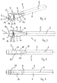
- FIG. 1 shown as an example of a medical instrument, a reamer, which at a terminal end of its instrument shaft, denoted by the reference numeral 78, has a Hudson connector or Trinkl adapter connection configuration, which is inserted into a quick coupling of a holder for fixing there, which Holder is fixed in the manner of a chuck with clamping claws, which engage by screwing a clamping sleeve into an undercut of the connecting end of the instrument shaft.
- Fig. 4 This document shows an alternative embodiment, in which the locking of the connection end of the instrument shaft takes place by means of locking balls.
- a novel holder for a medical, in particular surgical, instrument having the features of claim 1.
- Advantageous developments of such a holder are specified in the dependent claims 2 to 8.
- a further aspect of a solution of the object according to the invention then consists in a combination of a novel holder as described and at least one medical instrument detachably fixable in the holder with the features of claim 9 and corresponding advantageous further developments according to claims 10 and 11.
- a novel holder for a medical, in particular surgical, instrument has a quick coupling for receiving a connection end of an instrument shaft of the medical instrument which has an undercut.
- the quick coupling has a first coupling element with a first axial passage opening for the connection end.
- first and second coupling elements are movable relative to each other in a direction transverse to the axial direction of the through hole from a locking position in which the first and the second passage opening are offset from each other such that an edge of the second passage opening engages behind an undercut at the terminal end of the instrument shaft locking in a release position in which the first and the second axial passage opening are at least so far in alignment that the connection end can be passed freely through both passage openings.
- the first and the second coupling element are integrally connected to one another via a spring bridge, and the spring bridge biases the first and the second coupling element relative to one another into the locking position.
- the holder in its quick coupling initially eliminates the need small-scale and separate locking elements, such as locking balls to provide.
- the locking effect is effected solely by the offset of the two passage openings in the first and the second coupling element, which they have in the position assumed by the bias as a normal position locking position to each other in a direction transverse to the axial extent.
- a medical instrument guided through the first passage opening with the connection end of its instrument shaft is first of all set in the radial direction through this passage opening.
- An axial fixation or locking takes place in that the connecting end also projects through the second passage opening, wherein the second passage opening is displaced transversely to the axial direction relative to the first passage opening so that it rests with its edge on an undercut of the connection end, this engages behind and thus locking the instrument shaft in the axial direction.
- a certain axial play can still be present in this locking position. Often, such axial play, at least for hand-operated holders, is even desired by users because there is additional tactile help.
- the continued advantage of the holder according to the invention is that it is integrally formed in its connection between the first and second coupling element. This also eliminates a possible disassembly into individual parts and small parts that would be required when cleaning and sterilizing the holder.
- corresponding gaps between the elements integrally connected to each other can be created, which can be easily reached, cleaned and then sterilized with a corresponding cleaning instruments.
- extremely narrow interstices can be avoided, as they are given for example on ball bearing surfaces of locking balls and the cleaning and sterilization are hardly complete and sufficiently accessible for thorough cleaning and sterilization.
- the quick coupling may advantageously be formed in one piece as a whole and preferably consists of an easily sterilizable and sufficiently biocompatible material for operative use, in particular a medically compatible stainless steel.
- a metal there would be others medically usable metals such as titanium or titanium alloys into consideration
- the holder according to the invention can also advantageously have locking structures in its quick-action coupling for interacting with counter-structures at the connection end of the instrument shaft for a rotationally fixed arrangement of the instrument in the holder.
- Such a configuration is particularly relevant when with the holder rotational forces or torques on the medical instrument, e.g. a drill or a reamer, are to be transferred.
- One possible embodiment of forming such blocking structures is to arrange on the quick coupling on an outer end face of the first coupling element on opposite sides of the through opening on the front side through opening side jaws, which protrude from the surface on the front side to the outside and the Having the locking structures forming, parallel to each other and facing each other planar contact surfaces. In this case, these abutment surfaces are provided for abutment with mating surfaces formed at the connection end of the instrument shaft and forming counter-structures.
- This embodiment is a particularly simply constructed, easy-to-form in its structure design variant, which also meets the requirements of easy cleanability and sterilizability of the holder, especially in the field of quick release.
- the recess is sufficiently large, the gap between the wall of the main body and the spring bridge for the introduction of cleaning equipment is sufficiently far dimensioned, this section can be easily cleaned and sterilized.
- the recess also be angular, in particular follow in its course the angular shape of the course of the spring bridge and the angled extending to this second coupling element.
- the recess has a recess and the second coupling element has a projection (of course also in the reverse configuration, ie a projection on the recess and a recess on the coupling element), which together form a projection form a stop above the locking position relative movement of the coupling elements preventing stop.
- a stop prevents incorrect operation and increases the overall stability and reliability of the holder according to the invention.
- the spring bridge may lie on a lateral outer side of the holder and thereby be designed so that a force acting transversely to its longitudinal extent and against the spring action of the spring bridge force, in particular a compressive force can be applied to this manually, for Relocating the second coupling element from the latch position to the release position.
- the spring bridge is at the same time a "pressure switch", by the operation of the relative position of the first and the second coupling element to each other from the latch position can be transferred to the release position to in this position in particular a connected to the holder instrument from the holder If necessary, also insert an instrument with the connecting end of the instrument shaft into the quick coupling of the holder and fix it.
- the holder may in particular be a manually operable holder with a rotary shaft on which at a free end of the quick coupling is arranged and which also at an opposite end of the free end T-shaped a handle part is arranged.
- an inventive holder can be realized in other shaped manually operated designs, as it is also part of a motor-driven instrument drive, be it an actuated in the axial direction drive, be it a rotationally operated Drive, can be realized.
- this consists of a combination of a holder as described in more detail above and at least one medical, in particular surgical, instrument detachably fixable on the holder, which contains an instrument shaft having a connection end and in which an undercut is formed at the connection end of the instrument shaft is.
- the combination is not limited to a holder and a single instrument, it may at the same time also include a set consisting of one or more holders and one or more medical instruments.
- the instrument at the terminal end of its instrument shaft a thickening tapering away from the free end of the instrument shaft further, pointing away from the free end has, which falls back at its end remote from the free end to form the undercut, to a lesser extent of the instrument shaft.
- This conical thickening is used for easier insertion of the connecting end of the instrument shaft in the quick coupling, as displaced by the conical portion when applying an axially directed pressure force on the instrument shaft, the second coupling element of the quick coupling from the locking position and moved to the release position until the rear the cone lying undercut is achieved, the diameter of the instrument shaft falls back and the second coupling element snaps into the locking position.
- the instrument of such a combination at its connection end of the instrument shaft has the mating surfaces forming parallel flats.
- An inventive holder for a medical, in particular surgical instrument is shown in the figures in various (partial) views and generally designated by the reference numeral 1.
- the holder 1 in this embodiment is elongated formed with a shank portion 2.
- a quick coupling 3 is formed, which serves to receive an undercut having a connecting end of an instrument shaft of the medical instrument, with which the holder is to be connected ,
- the quick coupling 3 has a main body 26 and on whose end face 4 a receiving opening 5, which has the shape of a guided along a longitudinal axis 6 of the holder 1 bore.
- the quick coupling 3 is in particular formed in one piece and has two flattened side surfaces 7 and 8 and extending between these narrow sides 9 and 10, which extend wedge-shaped opening to one of the front side 4 nearby section, from where the narrow side 9, 10 rejuvenate , There go the narrow sides 9, 10 in two on the front side 4 protruding projections 11 and 12, respectively.
- a coupling plate 13 is formed by corresponding cutouts of the integral material of the quick coupling 3 and connected on one side with a separated by a slot 14 of the main body 26 of the quick coupling 3 spring bridge 15.
- the spring bridge 15 is integrally connected to the main body 26 of the quick coupling 3.
- the spring bridge 15 has a flattening 16 on its surface located on the narrow side 9, which flattening is formed as an ergonomic or haptic element for the plant of the thumb of a hand.
- handle recesses 17, 18, 19 are formed on the opposite Narrow side 10 handle recesses 17, 18, 19 are formed. These serve the plant of fingers, in particular index fingers, middle fingers and ring fingers of the hand, whose thumb rests in the flat 16.
- the spring tongue 14 can be deflected in the direction of the opposite narrow side 10 with one hand in order to effect a longitudinal displacement of the coupling plate 13 in the same direction.
- Clutch plate 13 and spring bridge 15 are, as already mentioned, integrally connected to each other and enclose an angle, so that the coupling plate 13 substantially perpendicular to the longitudinal axis 6 and thus the direction of the guided along this axis bore of the receiving opening 5.
- the coupling plate 13 is located in a receiving slot 27, which is in the quick coupling 3, more precisely in the main body 26, is formed, and at an angle to the slot 14 extends. In the receiving slot 27, the clutch plate 13 can move in a longitudinal direction.
- the receiving slot 27 and the slot 14 are at an angle to each other and together form an approximately L-shaped slot.
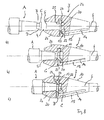
- a passage opening 20 is formed in the coupling plate 13, as in particular in the Fig. 6 can be seen.
- This passage opening 20 extends in its orientation also in the axial direction, ie with an extension direction parallel to the longitudinal axis 6, but is in the in Fig. 6 shown position in which the spring bridge 15 can be seen in an initial or rest position, with its central axis 21 relative to the longitudinal axis 6, which also forms the central axis of the receiving opening 5, offset.
- the receiving opening 5 extends beyond the portion in which the coupling plate 13 traverses them, up to an end portion 22.
- This can also be seen again in the front view according to Fig. 5 in which the offset axes of the central axis 21 and the longitudinal axis 6 are shown, as well as a view of the receiving opening 5 through which to be recognized by section of the coupling plate thirteenth
- Fig. 6 is also seen that in the shaft portion 2 of the holder 1 formed as a blind hole receptacle 23 is formed for connecting the holder 1 according to the invention with other structures, such as the drive shaft of a motorized instrument drive with a rotary drive or with a, for example, as transverse to the longitudinal extent of the holder 1, that is transverse to the longitudinal axis 6, in particular perpendicular to this, T-handle is used.
- other structures such as the drive shaft of a motorized instrument drive with a rotary drive or with a, for example, as transverse to the longitudinal extent of the holder 1, that is transverse to the longitudinal axis 6, in particular perpendicular to this, T-handle is used.
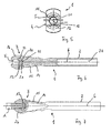
- the quick coupling 3 of the holder 1 according to the invention is for connection to a terminal end A (see. Fig. 7 ) of a staff of instruments.
- the quick coupling 3 or the connection end A is formed in particular as a so-called Hudson connection or a corresponding connection coupling.
- the quick coupling 3 of the holder is shown with the spring bridge 15 in a relaxed home or rest position.
- the receiving opening 5 and the passage opening 20 are not aligned in the coupling plate 13 in exact alignment.
- a section 24 of the coupling plate 13 which delimits the passage opening 20 protrudes into the region of the receiving opening 5 and thus covers in particular its end section 22.
- the coupling plate 13 has one of the front side 4 facing run-on slope 25 provided.
- connection end A of the instrument shaft has at its free end a region B of tapered diameter and a cover that covers this C.
- An undercut D is formed on this.
- the effect of the starting slope is sufficient 25 in conjunction with the conclusion C not to let the clutch plate 13 so far dodge in the direction of the narrow side 10 that the passage opening 20 is passable for the conclusion C, so here can be helped by hand by the spring bridge 15 by closing the Slot 14 is pressed in the direction of the opposite narrow side 10.
- the coupling plate 13 driven by the spring force of the spring bridge 15, can snap back into its rest or initial position.
- the portion 24 which lies above the undercut D at the terminal end A locks the terminal end A in the axial direction, i. in the direction of the longitudinal axis 6 of the holder.
- the spring bridge 15 has pressed in the direction of the opposite narrow side 10, thereby the coupling plate 13 are moved so that the passage opening 20 is exposed for a passage of the conclusion C and the terminal end A can be removed.
Landscapes
- Health & Medical Sciences (AREA)
- Surgery (AREA)
- Life Sciences & Earth Sciences (AREA)
- Biomedical Technology (AREA)
- Medical Informatics (AREA)
- Orthopedic Medicine & Surgery (AREA)
- Oral & Maxillofacial Surgery (AREA)
- Engineering & Computer Science (AREA)
- Dentistry (AREA)
- Heart & Thoracic Surgery (AREA)
- Nuclear Medicine, Radiotherapy & Molecular Imaging (AREA)
- Molecular Biology (AREA)
- Animal Behavior & Ethology (AREA)
- General Health & Medical Sciences (AREA)
- Public Health (AREA)
- Veterinary Medicine (AREA)
- Dental Tools And Instruments Or Auxiliary Dental Instruments (AREA)
- Surgical Instruments (AREA)
Priority Applications (10)
| Application Number | Priority Date | Filing Date | Title |
|---|---|---|---|
| EP12177714.8A EP2689730A1 (de) | 2012-07-24 | 2012-07-24 | Halter für ein medizinisches, insbesondere chirurgisches Instrument |
| IN2992KON2014 IN2014KN02992A (enExample) | 2012-07-24 | 2013-05-24 | |
| PCT/EP2013/060736 WO2014016011A1 (de) | 2012-07-24 | 2013-05-24 | Halter für ein medizinisches, insbesondere chirurgisches instrument |
| ES13724600.5T ES2602905T3 (es) | 2012-07-24 | 2013-05-24 | Soporte para un instrumento médico, especialmente para un instrumento quirúrgico |
| EP13724600.5A EP2877098B1 (de) | 2012-07-24 | 2013-05-24 | Halter für ein medizinisches, insbesondere chirurgisches instrument |
| JP2015523455A JP6074503B2 (ja) | 2012-07-24 | 2013-05-24 | ホルダおよび医療用器具 |
| US14/413,720 US9855059B2 (en) | 2012-07-24 | 2013-05-24 | Holder for a medical, in particular a surgical instrument |
| KR1020147031740A KR101932314B1 (ko) | 2012-07-24 | 2013-05-24 | 의료 기구, 특히 수술 기구용 홀더 |
| BR112014028001-0A BR112014028001B1 (pt) | 2012-07-24 | 2013-05-24 | Suporte para um instrumento médico, especialmente instrumento cirúrgico |
| CN201380032014.5A CN104379067B (zh) | 2012-07-24 | 2013-05-24 | 在医疗上尤其是外科手术器械的夹具 |
Applications Claiming Priority (1)
| Application Number | Priority Date | Filing Date | Title |
|---|---|---|---|
| EP12177714.8A EP2689730A1 (de) | 2012-07-24 | 2012-07-24 | Halter für ein medizinisches, insbesondere chirurgisches Instrument |
Publications (1)
| Publication Number | Publication Date |
|---|---|
| EP2689730A1 true EP2689730A1 (de) | 2014-01-29 |
Family
ID=48483090
Family Applications (2)
| Application Number | Title | Priority Date | Filing Date |
|---|---|---|---|
| EP12177714.8A Withdrawn EP2689730A1 (de) | 2012-07-24 | 2012-07-24 | Halter für ein medizinisches, insbesondere chirurgisches Instrument |
| EP13724600.5A Active EP2877098B1 (de) | 2012-07-24 | 2013-05-24 | Halter für ein medizinisches, insbesondere chirurgisches instrument |
Family Applications After (1)
| Application Number | Title | Priority Date | Filing Date |
|---|---|---|---|
| EP13724600.5A Active EP2877098B1 (de) | 2012-07-24 | 2013-05-24 | Halter für ein medizinisches, insbesondere chirurgisches instrument |
Country Status (9)
| Country | Link |
|---|---|
| US (1) | US9855059B2 (enExample) |
| EP (2) | EP2689730A1 (enExample) |
| JP (1) | JP6074503B2 (enExample) |
| KR (1) | KR101932314B1 (enExample) |
| CN (1) | CN104379067B (enExample) |
| BR (1) | BR112014028001B1 (enExample) |
| ES (1) | ES2602905T3 (enExample) |
| IN (1) | IN2014KN02992A (enExample) |
| WO (1) | WO2014016011A1 (enExample) |
Families Citing this family (7)
| Publication number | Priority date | Publication date | Assignee | Title |
|---|---|---|---|---|
| KR101719214B1 (ko) * | 2016-01-20 | 2017-04-04 | 김영재 | 외과용 핸드드릴 |
| EP3299036B1 (de) * | 2016-09-27 | 2019-06-12 | XYLEM Analytics Germany GmbH | Validierungsset sowie verfahren zum überprüfen der reinigungsleistung eines reinigungsapparats |
| CN107157543A (zh) * | 2017-05-20 | 2017-09-15 | 禹州市银星专用磨料有限公司 | 一种在骨外科手术中用棕刚玉骨刀 |
| WO2019157404A1 (en) * | 2018-02-09 | 2019-08-15 | Eca Medical Instruments | Ergonomic quick release plastic disposable base for medical instruments |
| WO2019157402A1 (en) * | 2018-02-09 | 2019-08-15 | Eca Medical Instruments | Cannulated ergonomic disposable plastic base for medical instruments |
| DE102019100016A1 (de) * | 2019-01-02 | 2020-07-02 | Aesculap Ag | Fügeverfahren für eine medizintechnische Vorrichtung |
| AU2024227340A1 (en) * | 2023-10-24 | 2025-05-08 | Howmedica Osteonics Corp. | Modular instrument and methods of using and manufacturing the modular instrument |
Citations (6)
| Publication number | Priority date | Publication date | Assignee | Title |
|---|---|---|---|---|
| US2784987A (en) * | 1954-02-03 | 1957-03-12 | Corcoran Richard Stanley | Pipe coupling with detent means |
| DE2909469B1 (de) | 1979-03-10 | 1980-07-31 | Howmedica Int Inc | Spannvorrichtung fuer chirurgische Werkzeuge |
| EP0893097A2 (de) | 1997-07-23 | 1999-01-27 | ESKA Implants GmbH & Co. | Halter für ein chirurgisches Instrument |
| DE10357104A1 (de) * | 2003-12-06 | 2005-07-14 | Richard Wolf Gmbh | Medizinisches Instrument |
| DE602004001063T2 (de) | 2003-02-04 | 2006-12-28 | Zimmer Technology, Inc., Chicago | Führungssystem für drehbares chirurgisches Instrument |
| EP1943966A1 (de) * | 2007-01-09 | 2008-07-16 | REINHARD Feinmechanik GmbH | Werkzeug für das Einbringen von Bohrungen in Knochen oder das Entnehmen von zylindrischen Bohrkernen aus Knochen des menschlichen Körpers |
Family Cites Families (22)
| Publication number | Priority date | Publication date | Assignee | Title |
|---|---|---|---|---|
| US3372950A (en) * | 1966-08-10 | 1968-03-12 | Lescoa Inc | Connecting apparatus |
| CH535042A (de) * | 1971-02-26 | 1973-03-31 | Woog Inst Rech | Steckvorrichtung an einem insbesondere zur Körperpflege dienenden Handgerät zur Befestigung auswechselbarer Behandlungsinstrumente |
| GB1441608A (en) * | 1973-12-06 | 1976-07-07 | Plas Plugs Ltd | Blade holders |
| US4224786A (en) * | 1977-09-09 | 1980-09-30 | Howard Langlie | Hand tool with readily detachable handle |
| US4409866A (en) * | 1981-12-28 | 1983-10-18 | Mcbride Joan | Tool handle with contoured through passageway and spring biased trigger |
| US4581961A (en) * | 1985-09-24 | 1986-04-15 | Lai Min D | Adjustable screw driver |
| DK52990D0 (da) * | 1990-03-01 | 1990-03-01 | Fiskars Zinck Lysbro As | Koblingsbeslag til et have- eller gartnerredskab |
| IT1258643B (it) * | 1992-07-28 | 1996-02-27 | Giovanni Faccioli | Fissatore dinamico assiale |
| US5816633A (en) * | 1997-04-03 | 1998-10-06 | Odom; Anthony K. | Handy dandy |
| US5957946A (en) * | 1997-07-30 | 1999-09-28 | Lab Medical Engineering & Manufacturing | Surgical bone awl |
| US6139214A (en) * | 1998-12-14 | 2000-10-31 | Endius Incorporated | Quick disconnect coupling for surgical instrument |
| US6315488B1 (en) * | 1999-08-09 | 2001-11-13 | Uniontools, Inc. | Snap-in handle assembly for a tool |
| JP3884698B2 (ja) * | 2002-11-11 | 2007-02-21 | 株式会社ナカニシ | 外科用工具の着脱機構及びこれを用いた外科用ハンドピース |
| GB2403448B (en) * | 2003-07-01 | 2007-01-10 | Graham Payne | Multifunctional tool |
| US20060090301A1 (en) * | 2004-11-01 | 2006-05-04 | Chih-Ching Hsieh | Tool handle device for providing greater torque to a driven object |
| US20060254398A1 (en) * | 2005-05-11 | 2006-11-16 | Vance Products Inc., D/B/A Cook Urological Inc. | Removable/replaceable handle device |
| US20070017072A1 (en) | 2005-07-19 | 2007-01-25 | Serio Craig S | Quick release connector |
| US7373860B1 (en) * | 2006-07-19 | 2008-05-20 | Rinner James A | Screwdriver T-handle |
| US7904987B2 (en) * | 2007-04-05 | 2011-03-15 | MagnaWand, Inc. | Cleaning tool |
| US8257386B2 (en) * | 2007-09-11 | 2012-09-04 | Cambridge Endoscopic Devices, Inc. | Surgical instrument |
| US20110030225A1 (en) * | 2009-08-10 | 2011-02-10 | Desheng Wang | Press-down type composite putty knife |
| US20120159794A1 (en) * | 2010-10-13 | 2012-06-28 | Metro Design Usa | Interchangeable Flatware Handles |
-
2012
- 2012-07-24 EP EP12177714.8A patent/EP2689730A1/de not_active Withdrawn
-
2013
- 2013-05-24 EP EP13724600.5A patent/EP2877098B1/de active Active
- 2013-05-24 IN IN2992KON2014 patent/IN2014KN02992A/en unknown
- 2013-05-24 BR BR112014028001-0A patent/BR112014028001B1/pt not_active IP Right Cessation
- 2013-05-24 CN CN201380032014.5A patent/CN104379067B/zh not_active Expired - Fee Related
- 2013-05-24 US US14/413,720 patent/US9855059B2/en active Active
- 2013-05-24 WO PCT/EP2013/060736 patent/WO2014016011A1/de not_active Ceased
- 2013-05-24 KR KR1020147031740A patent/KR101932314B1/ko not_active Expired - Fee Related
- 2013-05-24 ES ES13724600.5T patent/ES2602905T3/es active Active
- 2013-05-24 JP JP2015523455A patent/JP6074503B2/ja not_active Expired - Fee Related
Patent Citations (6)
| Publication number | Priority date | Publication date | Assignee | Title |
|---|---|---|---|---|
| US2784987A (en) * | 1954-02-03 | 1957-03-12 | Corcoran Richard Stanley | Pipe coupling with detent means |
| DE2909469B1 (de) | 1979-03-10 | 1980-07-31 | Howmedica Int Inc | Spannvorrichtung fuer chirurgische Werkzeuge |
| EP0893097A2 (de) | 1997-07-23 | 1999-01-27 | ESKA Implants GmbH & Co. | Halter für ein chirurgisches Instrument |
| DE602004001063T2 (de) | 2003-02-04 | 2006-12-28 | Zimmer Technology, Inc., Chicago | Führungssystem für drehbares chirurgisches Instrument |
| DE10357104A1 (de) * | 2003-12-06 | 2005-07-14 | Richard Wolf Gmbh | Medizinisches Instrument |
| EP1943966A1 (de) * | 2007-01-09 | 2008-07-16 | REINHARD Feinmechanik GmbH | Werkzeug für das Einbringen von Bohrungen in Knochen oder das Entnehmen von zylindrischen Bohrkernen aus Knochen des menschlichen Körpers |
Also Published As
| Publication number | Publication date |
|---|---|
| CN104379067B (zh) | 2016-12-21 |
| BR112014028001A2 (pt) | 2017-06-27 |
| ES2602905T3 (es) | 2017-02-22 |
| JP6074503B2 (ja) | 2017-02-01 |
| IN2014KN02992A (enExample) | 2015-05-08 |
| KR101932314B1 (ko) | 2019-03-20 |
| WO2014016011A1 (de) | 2014-01-30 |
| CN104379067A (zh) | 2015-02-25 |
| US9855059B2 (en) | 2018-01-02 |
| EP2877098B1 (de) | 2016-08-31 |
| KR20150037740A (ko) | 2015-04-08 |
| EP2877098A1 (de) | 2015-06-03 |
| JP2015523164A (ja) | 2015-08-13 |
| US20150141160A1 (en) | 2015-05-21 |
| BR112014028001B1 (pt) | 2021-04-13 |
Similar Documents
| Publication | Publication Date | Title |
|---|---|---|
| EP2877098B1 (de) | Halter für ein medizinisches, insbesondere chirurgisches instrument | |
| DE69520105T2 (de) | Modularer intramedullarnagel | |
| EP2962651B1 (de) | Medizinischer schraubendreher und schaft für den medizinischen schraubendreher | |
| EP2393435B1 (de) | Chirurgisches instrument zur lösbaren verbindung eines handstückes mit einem chirurgischen werkzeug | |
| EP2792305B1 (de) | Medizinisches Instrument | |
| EP2996585B1 (de) | Chirurgisches instrument | |
| EP2853212B1 (de) | Chirurgisches Instrument | |
| EP2846951A1 (de) | Schnellspann-kupplung | |
| EP2674116A1 (de) | Werkzeughalte- und Griffteil für ein medizinisches, insbesondere chirurgisches, Werkzeug | |
| EP1790292B1 (de) | Chirurgische Kupplungsvorrichtung | |
| DE102012101050B3 (de) | Ratsche und deren Herstellungsverfahren sowie Drehmomentübertragungssystem und Verfahren zum Übertragen eines Drehmoments auf ein Eindrehwerkzeug, und Verwendung einer derartigen Ratsche im Medizinbereich | |
| DE10220190B4 (de) | Chirurgisches Instrument | |
| EP3551104B1 (de) | Chirurgisches repositionsinstrument | |
| EP3711681B1 (de) | Vorspannbares verriegelungssystem | |
| DE102008029240B4 (de) | Verbindungsvorrichtung, insbesondere Schraube, mit Arretierfunktion zur lösbaren Verbindung von Werkstücken | |
| EP1303219B1 (de) | Medizinisches instrument, insbesondere resektoskop | |
| EP2919671A1 (de) | Markraumbohrer | |
| EP1539006A1 (de) | Intramedullärer osteosynthese-nagel zum versorgen von röhrenknochenfrakturen | |
| EP3000440A1 (de) | Endoprothese mit einer steckverbindung und verbesserter drehsicherung | |
| EP2258285B1 (de) | Medizinische Stanze | |
| DE102017120620B4 (de) | Knochenanker und Verlängerungsvorrichtung | |
| EP4311510B1 (de) | Medizinisches schlaginstrument | |
| DE102022116372B4 (de) | Chirurgisches instrument und verfahren zu dessen zerlegung | |
| DE102023121570B4 (de) | Schraubendreher für eine Innenprofilschraube | |
| EP2724692B1 (de) | Halter für ein medizinisches Implantat |
Legal Events
| Date | Code | Title | Description |
|---|---|---|---|
| PUAI | Public reference made under article 153(3) epc to a published international application that has entered the european phase |
Free format text: ORIGINAL CODE: 0009012 |
|
| AK | Designated contracting states |
Kind code of ref document: A1 Designated state(s): AL AT BE BG CH CY CZ DE DK EE ES FI FR GB GR HR HU IE IS IT LI LT LU LV MC MK MT NL NO PL PT RO RS SE SI SK SM TR |
|
| AX | Request for extension of the european patent |
Extension state: BA ME |
|
| STAA | Information on the status of an ep patent application or granted ep patent |
Free format text: STATUS: THE APPLICATION IS DEEMED TO BE WITHDRAWN |
|
| 18D | Application deemed to be withdrawn |
Effective date: 20140730 |