EP2688797B1 - Aircraft window and installation method - Google Patents
Aircraft window and installation method Download PDFInfo
- Publication number
- EP2688797B1 EP2688797B1 EP12704636.5A EP12704636A EP2688797B1 EP 2688797 B1 EP2688797 B1 EP 2688797B1 EP 12704636 A EP12704636 A EP 12704636A EP 2688797 B1 EP2688797 B1 EP 2688797B1
- Authority
- EP
- European Patent Office
- Prior art keywords
- window
- receptacle
- aircraft
- seal
- window assembly
- Prior art date
- Legal status (The legal status is an assumption and is not a legal conclusion. Google has not performed a legal analysis and makes no representation as to the accuracy of the status listed.)
- Active
Links
Images


Classifications
-
- B—PERFORMING OPERATIONS; TRANSPORTING
- B64—AIRCRAFT; AVIATION; COSMONAUTICS
- B64C—AEROPLANES; HELICOPTERS
- B64C1/00—Fuselages; Constructional features common to fuselages, wings, stabilising surfaces or the like
- B64C1/14—Windows; Doors; Hatch covers or access panels; Surrounding frame structures; Canopies; Windscreens accessories therefor, e.g. pressure sensors, water deflectors, hinges, seals, handles, latches, windscreen wipers
- B64C1/1476—Canopies; Windscreens or similar transparent elements
- B64C1/1492—Structure and mounting of the transparent elements in the window or windscreen
-
- B—PERFORMING OPERATIONS; TRANSPORTING
- B21—MECHANICAL METAL-WORKING WITHOUT ESSENTIALLY REMOVING MATERIAL; PUNCHING METAL
- B21D—WORKING OR PROCESSING OF SHEET METAL OR METAL TUBES, RODS OR PROFILES WITHOUT ESSENTIALLY REMOVING MATERIAL; PUNCHING METAL
- B21D53/00—Making other particular articles
- B21D53/92—Making other particular articles other parts for aircraft
-
- Y—GENERAL TAGGING OF NEW TECHNOLOGICAL DEVELOPMENTS; GENERAL TAGGING OF CROSS-SECTIONAL TECHNOLOGIES SPANNING OVER SEVERAL SECTIONS OF THE IPC; TECHNICAL SUBJECTS COVERED BY FORMER USPC CROSS-REFERENCE ART COLLECTIONS [XRACs] AND DIGESTS
- Y10—TECHNICAL SUBJECTS COVERED BY FORMER USPC
- Y10T—TECHNICAL SUBJECTS COVERED BY FORMER US CLASSIFICATION
- Y10T29/00—Metal working
- Y10T29/49—Method of mechanical manufacture
- Y10T29/49826—Assembling or joining
- Y10T29/49863—Assembling or joining with prestressing of part
- Y10T29/49876—Assembling or joining with prestressing of part by snap fit
Definitions
- the present disclosure generally relates to window assemblies, and deals more particularly with a window for aircraft, and a related method of window installation.
- the invention relates to an aircraft window having the features of the preamble of claim 1 and to a method of installing a window on an aircraft fuselage including the steps of the preamble of claim 7.
- Such an aircraft window and such an installation method are known from US 2007/095984 A1 .
- Windows used in aircraft having pressurized cabins may be required to withstand substantial pressure differentials during flight, while insulating the cabin interior from harsh exterior environments.
- a window assembly has been used that comprises an outboard structural window mounted on the aircraft's exterior skin and an inboard transparent window mounted on interior cabin sidewall panels.
- a cavity between the two windows is sealed by a peripheral seal that is compressed against the outboard structural window by the interior side wall panel that surrounds the window opening.
- the window is assembled and installed using a combination of frictional fit, spring clips between the structural window and the seal.
- the window assembly described above may have some challenges in some applications. For example, if the sidewall panels are not supported locally around the perimeter, this may reduce compression of the seal against the outboard structural window. Another challenge of the prior window assembly is it may allow moisture buildup on surfaces inside the window cavity. In addition, the prior window assembly is relatively time consuming to install and may not provide the installer with an audible indication of whether the seal has been adequately seated against the structural window and compressed with a sufficient amount of compressive force on the seal.
- the disclosed embodiments provide a window construction and related method for installing the window on an aircraft.
- the window provides improved sealing that may reduce or eliminate condensation and frost buildup within an internal window cavity.
- the window may increase the compression of a seal against an outer structural window to form a substantially air tight seal around the window cavity.
- the window construction includes interlocking retention clips and receptacles that may reduce installation time.
- an aircraft window having the features as defined in claim 1.
- Preferred embodiments of the aircraft window of the invention form the subject-matter of dependent claims 2-6.
- a method is provided of installing a window on an aircraft fuselage as defined in claim 7. Preferred ways of carrying out this method form the subject-matter of dependent claims 8-12.
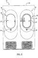
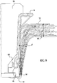
- each of the windows 20 may include an inner window assembly 23 mounted on interior side wall panel assembly 82 forming part of a cabin (not shown) within the fuselage 21.
- the inner window assembly 23 includes a peripheral inner reveal assembly 84 surrounding a window opening 27 ( FIG. 2 ).
- the window 20 may comprise an electronically dimmable window 22 (see FIG. 4A ) whose transparency can be electrically controlled. For example and without limitation, passengers or crew may control the dimmable window 22 using an electrical switch 25 located beneath each window 20 on the sidewall panel assembly 82, or located remotely.
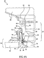
- the window 20 broadly comprises an inner window assembly 23 that is retained on an outer window assembly 33 (see FIG. 4A ) by a plurality of snap-fit retaining and locking features 68.
- the outer window assembly 33 includes an outboard structural window 26 mounted on a frame 30 that is attached by any suitable means (not shown) to the outer skin 86 of the aircraft.
- a suitable structural window seal 28 forming part of the outer window assembly 33 is captured between the structural window 26 and the frame 30 to form a substantially air tight seal around the periphery of the outboard structural window 26.
- the outer window assembly 33 also includes a plurality of structural window support brackets 36, which are substantially L-shaped in cross section and are mounted by any suitable means such as fasteners (not shown), to the frame 30 about the latter's periphery.
- a spring clip 32 is mounted on each of the brackets 36 by means of a spring fastener 96.
- a receptacle 34 is mounted on one end of each of the spring clips 32 at the periphery of the structural window 26.
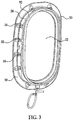
- the inner window assembly 23 includes an inboard window or lens 22 and a compressible seal 24 that extends around the perimeter of the inner window assembly 23 and may be formed of any suitable material.
- the outer perimeter of the inboard window 22 is held within the seal 24.
- the seal 24 is spaced inboard of the outboard structural window 26 to form an outboard window cavity 80.
- the seal 24 has a tear-shaped outboard portion 78 that contacts and is sealed against the structural window 26 to form an air-tight seal around the outboard window cavity 80.
- the tear-shaped portion 78 may fold as it contacts and is compressed against the window 26, resulting in a seal that has more surface area while permitting the seal 24 to open slightly and "burp" to bleed and release air when the air pressure inside the cavity becomes too great and exceeds a preselected value.
- the seal 24 may also include an inboard bellows seal 88 forming a seal against a reveal assembly 84 that comprises an outboard reveal 90 and the inboard reveal 92.
- the inner window assembly 23 may further include an inboard reveal window 94, a reveal assembly 84 having an inboard reveal 92 and a plurality of retention clips 38.
- the periphery of the reveal window 94 also sometimes referred to as a dust cover, is captured within the reveal assembly 84 in the space inboard of the inboard window 22.
- the upper end of the seal 24 includes a bellows portion 88 that is sealed against the reveal assembly 84.
- Each of the retention clips 38 is bonded to or may be molded within the peripheral seal 24.
- One end of each of the retention clips 38 includes a finger tab 40, and the other end of the retention clip 38 includes a plug 44 that is received in snap-fit relationship within the receptacle 34.
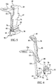
- FIG. 4B shows the relative alignment between the inner and outer window assemblies 23, 33, and particularly the retention clips 38 and the receptacles 34 during the installation of the window 20.
- the inner and outer window assemblies 23, 33 are aligned such that the plugs 44 on the retention clips 38 are approximately aligned along a line shown at 104, with the corresponding receptacles 34 that are mounted on the window frame 30.
- the installer may press on the finger tabs 40 to apply force shown at 100 which forces the plugs 44 into the receptacles 34, thereby retaining the inner window assembly 23 on the frame 30 while generating a retention force that compresses the outboard portion 78 of the seal 24 against the interior surface 75 of the structural window 26.
- FIGS. 5, 6 and 7A-7C illustrate additional details of the snap-fit interlocking connections between the inner and outer window assemblies 23, 33 shown in FIGS. 4A and 4B .
- the spring clip 32 includes an upper apertured end 32a and a lower spring bend 50 connected by a slightly curved section 32b.
- the spring clip 32 may be manufactured of any suitable material such as metal that has spring like characteristics.
- a spring tab 48 extending from the spring bend 50 is received within a spring tab pocket 54 in the receptacle 34.
- the retention clip 38 includes a substantially flat bonding surface 76 and may include wing tabs 42 to increase the surface bonding area of the retention clip 38 when it is bonded to the seal 24 ( FIGS. 3A, 3B ).
- the receptacle 34 may be manufactured of any suitable material that has flexible, spring like characteristics, such as, without limitation, a thermoplastic.
- the receptacles include a pair of facing retention knobs 52 respectively on flexible end wall flanges 66. The retention knobs 52 are received within opposite open ends 53 of the spring bend 50 in spring clip 32 and function to assist in retaining the receptacle 34 on the spring clip 32.
- the retention knobs 52 allow the installer to install the receptacles on the spring clip 32 prior to installation of the spring clip 32 on the frame 30.
- the end wall flanges 66 may flex to some degree to aid in the installation of the receptacle 34 on the spring clip 32 by allowing the knobs 52 to engage the spring bend 50.
- This design allows the receptacle 34 to remain attached to the spring clip 32 while the spring clip 32 is being installed.
- the receptacle 34 includes vertical and horizontal exterior surfaces 60, 62 respectively, which bear against and assist in retaining and sealing the structural window 26 to the window frame 30 (see FIG. 4A and 4B ).
- the receptacle 34 includes a receptacle socket 46 having a socket opening 74 therein.
- the receptacle 34 also includes a pair of flexible guides 56 on opposite sides of the socket opening 74 which are inclined at a pre-selected angle 64 ( FIG. 7C ) relative to a line 104 ( FIG. 4B ) along which the window assemblies are assembled.
- the width 98 FIG.
- the socket opening 74 is slightly less than the diameter D of the retention clip plug 44, but widens to allow passage of the plug 44 when the plug 44 is inserted into the socket 46, and then snaps back to at least its former width 98, due to the spring quality of the receptacle 34.
- This differential in size between the diameter D of the plug 30 and the width 98 of the socket opening 74 forms a snap-fit locking feature 68 which retains the plug 38 in the receptacle 34 after assembly, thereby locking the retention clip 38 to the spring clip 32.
- the locking feature 68 also produces a retention force that compresses the lower end of the seal 24 against the structural window 26, thereby providing an airtight seal continuously around outboard window cavity 80 ( FIG. 4A ).
- This substantially air-tight seal resulting from compression of the seal 24 against the structural window 26 which folds and compresses the tear-shaped portion 78 against the structural window 26, may prevent air condensation and frost build up within the inboard window cavity 80.
- the receptacle socket 46 has a width 72 that is slightly greater than the width 70 of the retention clip 38.
- the opposite ends of the socket 46 are substantially open, as best seen in FIGS. 5, 6 and 7A .
- providing the socket 46 with open ends and orienting the guides 56 at an angle 64 relative to the line of assembly 104 allows for variations that may occur during a window assembly installation process.
- the disclosed configuration of the retention clip 38 and the receptacle 34 allow for variations in the height 65 and/or angle 67 of the spring clip 32.
- the configuration of the socket 46 and the plug 44 allow some degree of non-alignment between the spring clip 32 and the retention clip 38, since a portion 85 of the plug 44 may extend beyond the ends of the socket 46 after assembly.
- the inclination of the guides 56 on the receptacle 34 allow the plug 44 to rotate slightly within the socket 46 during the window assembly installation process, thereby accommodating possible variations in the angle 77 of the retention clip 38 relative to the receptacle.
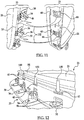
- FIG. 11 illustrates an inner window assembly 23 about to be installed on an outer window assembly 33.
- the inner window assembly 23 is rotated into alignment with the outer window assembly 33 such that the plugs 44 are aligned and guided into contact with corresponding ones of the receptacles 34.
- the installer applies a force as shown by the arrows 100 using fingers or a tool to the finger tabs 40.
- This applied force forces the plugs 40 down into the sockets 46, thereby locking the inner window assembly 23 on the outer window assembly 33 at multiple locations around the periphery of the frame 30.
- the retention force produced by the locking feature 68 results in a positive and appropriate force being applied to the foam seal 24 ( FIG.
- an audible "snap" may be heard by the installer, providing the installer with feedback confirmation that the particular retention clip 38 has been positively locked in the receptacle 34.
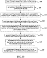
- FIG. 13 illustrates the overall steps of a method of installing a window 20 on an aircraft.
- mounting brackets 36 are installed on window frame 30.
- the outer structural window 26 is mounted on the frame 30.
- receptacles 34 are installed on spring clips 32 which are in turn secured to the mounting brackets 36 to form a pre-assemble outer window assembly 33 that is installed on the aircraft, at 112, by mounting the frame 30 on the skin 86 or other structure of the aircraft.
- an outer cavity seal 24 is installed on an inner window assembly 23, which may include one or more inboard windows 22, 94, as previously described, and retention clips 38 are mounted on the inner window assembly 23, as by bonding or integrally molding the retention clips 38 to the seal 24.
- the inner window assembly 23 is positioned over the outer window assembly 33 such that the retention clips 38 and particularly the plugs 44 are aligned with the socket openings 74 in the receptacles 34.
- the plugs 44 of the retention clips 38 are pressed into receptacle sockets 74 by pressing the finger tabs 40 on the retention clips 38.
- the installer may confirm locking of the retention clips 38 with the receptacles 34 by listening for an audible "snap".
- Embodiments of the disclosure may find use in a variety of potential applications, particularly in the transportation industry, including for example, aerospace, marine and automotive applications.
- Aircraft applications of the disclosed embodiments may include, for example, windows 145 installed on the airframe 140 of the aircraft 124.
- exemplary method 120 may include specification and design 126 of the aircraft 124 and material procurement 128.
- component and subassembly manufacturing 130 and system integration 132 of the aircraft 124 takes place. Thereafter, the aircraft 124 may go through certification and delivery 134 in order to be placed in service 136. While in service by a customer, the aircraft 124 is scheduled for routine maintenance and service 138 (which may also include modification, reconfiguration, refurbishment, and so on).
- a system integrator may include without limitation any number of aircraft manufacturers and major-system subcontractors; a third party may include without limitation any number of vendors, subcontractors, and suppliers; and an operator may be an airline, leasing company, military entity, service organization, and so on.
- the aircraft 124 produced by exemplary method 120 may include an airframe 140 with a plurality of systems 142, an interior 144 and one or more windows 145.
- high-level systems 142 include one or more of a propulsion system 148, an electrical system 148, a hydraulic system 150, and an environmental system 152. Any number of other systems may be included.
- an aerospace example is shown, the principles of the disclosure may be applied to other industries, such as the marine and automotive industries.
- Systems and methods embodied herein may be employed during any one or more of the stages of the production and service method 120.
- components or subassemblies corresponding to production process 130 may be fabricated or manufactured in a manner similar to components or subassemblies produced while the aircraft 124 is in service.
- one or more apparatus embodiments, method embodiments, or a combination thereof may be utilized during the production stages 130 and 132, for example, by substantially expediting assembly of or reducing the cost of an aircraft 124.
- apparatus embodiments, method embodiments, or a combination thereof may be utilized while the aircraft 124 is in service, for example and without limitation, to maintenance and service 138.
- the window where the socket includes flexible guides on opposite sides of the socket opening for guiding the plug into the socket during the installation.
- the window further includes at least one bracket attached to the frame, and a deformable spring member mounted on the bracket, wherein the receptacle is mounted on an end of the deformable spring member.
- an aircraft window in another example, includes an outer window assembly an inner window assembly adapted to be installed on the outer window assembly; a seal adapted to be compressed between the inner and outer window assemblies; and a plurality of retaining features for retaining the inner window assembly on the outer window assembly and for producing an audible indication when the seal has been sufficiently compressed during the installation.
- a window for an aircraft fuselage includes an outer window assembly, including a window frame adapted to be mounted on the fuselage, an outboard structural window mounted on the window frame, a seal between the window frame and the outboard structural window, a plurality of brackets on the window frame around the periphery of the outboard structural window, a plurality of spring clips respectively secured to the brackets, a flexible receptacle mounted on each of the spring clips and having a socket with a socket opening; and an inner window assembly adapted to be installed on the outer window assembly, including an inboard window spaced inboard of the outboard structural window to form a cavity between the inboard and outboard windows when the inner window is installed on the outer window assembly, a compressible seal around the periphery of the window for sealing the cavity, a plurality of elongate retention clips respectively associated with the spring clips to form retaining features connecting the inner window assembly with the outer window assembly, the retention clips being bonded to the seal and spaced around a periphery of the inner window assembly
- a method of installing a window on the fuselage of an aircraft includes assembling an outer window assembly by mounting a window frame on the fuselage, mounting an outboard structural window on the window frame, placing a first seal between the outboard window and the frame, mounting a plurality of brackets on the frame, mounting a plurality of spring clips respectively on the brackets, mounting a receptacle on an and of each of the spring clips; assembling an inner window assembly by mounting an inner window on a sidewall panel of the fuselage, attaching a second seal to the inner window, attaching a plurality of retention clips to the second seal, aligning the inner and outer window assemblies; placing the inner window assembly on the outer window assembly; and retaining the inner window assembly on the outer window assembly, including inserting a plug on each of the retention clips into a socket on a corresponding one of the receptacles by applying force to one end of the retention clip until an audible snap is heard.
Landscapes
- Engineering & Computer Science (AREA)
- Mechanical Engineering (AREA)
- Aviation & Aerospace Engineering (AREA)
- Securing Of Glass Panes Or The Like (AREA)
- Connection Of Plates (AREA)
- Specific Sealing Or Ventilating Devices For Doors And Windows (AREA)
- Connector Housings Or Holding Contact Members (AREA)
Priority Applications (1)
| Application Number | Priority Date | Filing Date | Title |
|---|---|---|---|
| EP17201737.8A EP3395673B1 (en) | 2011-03-25 | 2012-02-10 | Aircraft window and installation method |
Applications Claiming Priority (2)
| Application Number | Priority Date | Filing Date | Title |
|---|---|---|---|
| US13/071,823 US8944381B2 (en) | 2011-03-25 | 2011-03-25 | Aircraft window and installation method |
| PCT/US2012/024721 WO2012134646A1 (en) | 2011-03-25 | 2012-02-10 | Aircraft window and installation method |
Related Child Applications (1)
| Application Number | Title | Priority Date | Filing Date |
|---|---|---|---|
| EP17201737.8A Division EP3395673B1 (en) | 2011-03-25 | 2012-02-10 | Aircraft window and installation method |
Publications (2)
| Publication Number | Publication Date |
|---|---|
| EP2688797A1 EP2688797A1 (en) | 2014-01-29 |
| EP2688797B1 true EP2688797B1 (en) | 2017-11-15 |
Family
ID=45688298
Family Applications (2)
| Application Number | Title | Priority Date | Filing Date |
|---|---|---|---|
| EP12704636.5A Active EP2688797B1 (en) | 2011-03-25 | 2012-02-10 | Aircraft window and installation method |
| EP17201737.8A Active EP3395673B1 (en) | 2011-03-25 | 2012-02-10 | Aircraft window and installation method |
Family Applications After (1)
| Application Number | Title | Priority Date | Filing Date |
|---|---|---|---|
| EP17201737.8A Active EP3395673B1 (en) | 2011-03-25 | 2012-02-10 | Aircraft window and installation method |
Country Status (7)
| Country | Link |
|---|---|
| US (2) | US8944381B2 (enExample) |
| EP (2) | EP2688797B1 (enExample) |
| JP (1) | JP6010603B2 (enExample) |
| CN (1) | CN103534167B (enExample) |
| CA (1) | CA2829212C (enExample) |
| ES (2) | ES2659749T3 (enExample) |
| WO (1) | WO2012134646A1 (enExample) |
Families Citing this family (21)
| Publication number | Priority date | Publication date | Assignee | Title |
|---|---|---|---|---|
| DE102011108167B4 (de) * | 2011-07-20 | 2014-02-13 | Airbus Operations Gmbh | Fenstertrichter sowie Fensterbereich für ein Flugzeug |
| US9415854B2 (en) * | 2011-09-14 | 2016-08-16 | Mitsubishi Aircraft Corporation | Aircraft window and aircraft having an electromagnetic shield |
| US9221533B1 (en) * | 2011-10-24 | 2015-12-29 | The Boeing Company | Removable window system for space vehicles |
| US9168812B2 (en) | 2012-10-31 | 2015-10-27 | The Boeing Company | Decorative ring device for free-floating interface of aircraft interior sidewall window lining |
| US20140209746A1 (en) * | 2013-01-29 | 2014-07-31 | The Boeing Company | Window shading assembly |
| USD728446S1 (en) * | 2013-05-21 | 2015-05-05 | Airbus Corporate Jet Centre | Aircraft window |
| US9340275B2 (en) | 2014-02-25 | 2016-05-17 | Textron Innovations, Inc. | Window assembly installation |
| WO2016201087A1 (en) | 2015-06-09 | 2016-12-15 | Gentex Corporation | Retention of an electro-optic window assembly |
| US10167073B2 (en) | 2015-06-09 | 2019-01-01 | Gentex Corporation | Multi-piece bezel for electro-optic window assembly |
| CN108025807B (zh) * | 2015-09-22 | 2021-03-05 | 庞巴迪公司 | 用于给窗户腔体通气并减少其内水分的无源系统和方法 |
| DE102016105894A1 (de) * | 2016-03-31 | 2017-10-05 | E.I.S. Aircraft Gmbh | Fahrzeugvorrichtung und Verfahren mit einer Fahrzeugvorrichtung |
| EP3246243B1 (en) * | 2016-05-19 | 2018-11-28 | Airbus Operations GmbH | Window assembly for an aircraft |
| EP3293106B1 (en) * | 2016-09-07 | 2018-11-14 | Leonardo S.p.A. | Window with an emergency exit function for a helicopter and method for removing a transparent element from this window |
| JP6890049B2 (ja) * | 2017-06-23 | 2021-06-18 | 東海旅客鉄道株式会社 | 鉄道車両 |
| US11014678B2 (en) * | 2018-04-25 | 2021-05-25 | Roberto Antonio Ogarrio | Aircraft window plug device |
| US11407486B2 (en) * | 2019-11-14 | 2022-08-09 | The Boeing Company | Window clamp system for a vehicle |
| DE102020000356B4 (de) * | 2020-01-22 | 2021-08-12 | Diehl Aviation Laupheim Gmbh | Fenstereinheit für ein Flugzeug, Flugzeug mit der Fenstereinheit sowie Verfahren zur Montage der Fenstereinheit |
| CN112960136B (zh) * | 2021-02-08 | 2023-02-03 | 中国商用飞机有限责任公司 | 封堵装置、飞行器窗及其封堵方法 |
| CN113200151B (zh) * | 2021-05-10 | 2023-01-13 | 中航西安飞机工业集团股份有限公司 | 一种大型飞机舱门高精度定力装配方法 |
| US12054980B2 (en) | 2022-03-18 | 2024-08-06 | Raytheon Company | Panel assembly with mullion joint |
| FR3143542A1 (fr) * | 2022-12-15 | 2024-06-21 | Airbus Operations (S.A.S.) | Procédé de fabrication d’un cadre de hublot d’aéronef comportant une couche barrière, cadre de hublot obtenu à partir de ce procédé et aéronef comprenant au moins un tel cadre de hublot |
Family Cites Families (15)
| Publication number | Priority date | Publication date | Assignee | Title |
|---|---|---|---|---|
| US2409808A (en) * | 1942-02-19 | 1946-10-22 | Lockheed Aircraft Corp | Glazing unit |
| US4541595A (en) | 1983-03-28 | 1985-09-17 | Heath-Tecna Precision Structures | Removable interior window unit for aircraft |
| US5271581A (en) * | 1992-05-29 | 1993-12-21 | Irish Michael J | Window clip for aircraft |
| US6431250B2 (en) * | 2000-03-08 | 2002-08-13 | Wayne-Dalton Corporation | Apparatus and method for windlocking a building opening |
| US6786453B2 (en) | 2001-10-25 | 2004-09-07 | The Boeing Company | Snap-in window assembly and method |
| US6793182B2 (en) | 2002-03-25 | 2004-09-21 | The Boeing Company | Window attachment system |
| US7300693B2 (en) | 2003-09-04 | 2007-11-27 | The Boeing Company | Resin infused transparent skin panel and method of making same |
| US7028950B2 (en) | 2004-05-10 | 2006-04-18 | The Boeing Company | Load bearing window |
| US7578474B2 (en) | 2005-06-02 | 2009-08-25 | The Boeing Company | Sealed structural passenger window assembly and method of forming same |
| US7661626B2 (en) | 2005-10-28 | 2010-02-16 | The Boeing Company | Window assembly retaining system |
| US7281686B2 (en) * | 2005-11-02 | 2007-10-16 | The Boeing Company | Window assembly for aircraft fuselage |
| US7562846B2 (en) | 2005-11-10 | 2009-07-21 | The Boeing Company | Window retaining system |
| US7552896B2 (en) * | 2006-02-21 | 2009-06-30 | The Boeing Company | Aircraft window assembly |
| US7823833B2 (en) | 2007-03-05 | 2010-11-02 | The Boeing Company | Window installation method and apparatus |
| US8449709B2 (en) * | 2007-05-25 | 2013-05-28 | The Boeing Company | Method of fabricating fiber reinforced composite structure having stepped surface |
-
2011
- 2011-03-25 US US13/071,823 patent/US8944381B2/en active Active
-
2012
- 2012-02-10 EP EP12704636.5A patent/EP2688797B1/en active Active
- 2012-02-10 WO PCT/US2012/024721 patent/WO2012134646A1/en not_active Ceased
- 2012-02-10 CN CN201280014430.8A patent/CN103534167B/zh active Active
- 2012-02-10 ES ES12704636.5T patent/ES2659749T3/es active Active
- 2012-02-10 CA CA2829212A patent/CA2829212C/en active Active
- 2012-02-10 JP JP2014501070A patent/JP6010603B2/ja active Active
- 2012-02-10 ES ES17201737T patent/ES2857733T3/es active Active
- 2012-02-10 EP EP17201737.8A patent/EP3395673B1/en active Active
-
2015
- 2015-02-02 US US14/611,605 patent/US9714078B2/en active Active
Non-Patent Citations (1)
| Title |
|---|
| None * |
Also Published As
| Publication number | Publication date |
|---|---|
| ES2857733T3 (es) | 2021-09-29 |
| US20150143684A1 (en) | 2015-05-28 |
| EP2688797A1 (en) | 2014-01-29 |
| US9714078B2 (en) | 2017-07-25 |
| CA2829212C (en) | 2019-06-18 |
| US20120241559A1 (en) | 2012-09-27 |
| CN103534167A (zh) | 2014-01-22 |
| CA2829212A1 (en) | 2012-10-04 |
| CN103534167B (zh) | 2015-11-25 |
| ES2659749T3 (es) | 2018-03-19 |
| JP6010603B2 (ja) | 2016-10-19 |
| JP2014508684A (ja) | 2014-04-10 |
| US8944381B2 (en) | 2015-02-03 |
| WO2012134646A1 (en) | 2012-10-04 |
| EP3395673A1 (en) | 2018-10-31 |
| EP3395673B1 (en) | 2020-11-25 |
Similar Documents
| Publication | Publication Date | Title |
|---|---|---|
| EP2688797B1 (en) | Aircraft window and installation method | |
| US5044578A (en) | Universal cabin sidewall panel for aircraft | |
| US9499251B2 (en) | Decompression panel for use in an aircraft | |
| US8826597B2 (en) | Weatherproof surround for safely jettisoning a removable panel | |
| US20100044513A1 (en) | Aircraft cabin window assembly method | |
| US20140053479A1 (en) | Sash binder | |
| EP3060382A1 (en) | Vacuum bag sealing system and method for composite parts | |
| US9090330B2 (en) | Opening plug and method of installing the same | |
| EP2942550A1 (en) | System and apparatus for aerodynamically sealing surfaces | |
| CN113371176A (zh) | 用于飞行器增压区舱门的密封件和配备有该密封件的飞行器增压区舱门 | |
| KR102650145B1 (ko) | 파손 발생시 받아 들이는 개구부에서 차단될 수 있게 하는, 특히 항공기를 위한 글레이징 유닛 (glazing unit) | |
| EP3730284B1 (en) | Composite panel systems and methods | |
| US20140273787A1 (en) | Air Duct Assembly and Method of Installing the Same | |
| EP4682048A2 (en) | Vehicle cabin sidewall-to-floor coupling assembly and method of assembly | |
| CA2983508C (en) | Apparatuses and methods for aerodynamic window assemblies | |
| WO2015060925A1 (en) | Clamp device for use with a decompression panel in an aircraft assembly | |
| US2132688A (en) | Window mounting for streamlined vehicles | |
| US12060145B2 (en) | Vehicle panel assembly and method of panel assembly | |
| CN112960136A (zh) | 封堵装置、飞行器窗及其封堵方法 | |
| US10464657B2 (en) | Insulation blanket heat seal grommet and system for maintaining full insulation filler material thickness and methods for the same | |
| US10717900B2 (en) | Sealant tape and methods using sealant tape |
Legal Events
| Date | Code | Title | Description |
|---|---|---|---|
| PUAI | Public reference made under article 153(3) epc to a published international application that has entered the european phase |
Free format text: ORIGINAL CODE: 0009012 |
|
| 17P | Request for examination filed |
Effective date: 20131021 |
|
| AK | Designated contracting states |
Kind code of ref document: A1 Designated state(s): AL AT BE BG CH CY CZ DE DK EE ES FI FR GB GR HR HU IE IS IT LI LT LU LV MC MK MT NL NO PL PT RO RS SE SI SK SM TR |
|
| RIN1 | Information on inventor provided before grant (corrected) |
Inventor name: KELSEY, JEFFREY LEE Inventor name: EBNER, JAMES E. Inventor name: BRYAN, ERIC ALLEN |
|
| DAX | Request for extension of the european patent (deleted) | ||
| GRAP | Despatch of communication of intention to grant a patent |
Free format text: ORIGINAL CODE: EPIDOSNIGR1 |
|
| INTG | Intention to grant announced |
Effective date: 20170602 |
|
| GRAS | Grant fee paid |
Free format text: ORIGINAL CODE: EPIDOSNIGR3 |
|
| GRAA | (expected) grant |
Free format text: ORIGINAL CODE: 0009210 |
|
| AK | Designated contracting states |
Kind code of ref document: B1 Designated state(s): AL AT BE BG CH CY CZ DE DK EE ES FI FR GB GR HR HU IE IS IT LI LT LU LV MC MK MT NL NO PL PT RO RS SE SI SK SM TR |
|
| REG | Reference to a national code |
Ref country code: CH Ref legal event code: EP Ref country code: GB Ref legal event code: FG4D Ref country code: AT Ref legal event code: REF Ref document number: 945983 Country of ref document: AT Kind code of ref document: T Effective date: 20171115 |
|
| REG | Reference to a national code |
Ref country code: IE Ref legal event code: FG4D |
|
| REG | Reference to a national code |
Ref country code: DE Ref legal event code: R096 Ref document number: 602012039751 Country of ref document: DE |
|
| REG | Reference to a national code |
Ref country code: FR Ref legal event code: PLFP Year of fee payment: 7 |
|
| REG | Reference to a national code |
Ref country code: ES Ref legal event code: FG2A Ref document number: 2659749 Country of ref document: ES Kind code of ref document: T3 Effective date: 20180319 |
|
| REG | Reference to a national code |
Ref country code: NL Ref legal event code: MP Effective date: 20171115 |
|
| REG | Reference to a national code |
Ref country code: LT Ref legal event code: MG4D |
|
| REG | Reference to a national code |
Ref country code: AT Ref legal event code: MK05 Ref document number: 945983 Country of ref document: AT Kind code of ref document: T Effective date: 20171115 |
|
| PG25 | Lapsed in a contracting state [announced via postgrant information from national office to epo] |
Ref country code: NO Free format text: LAPSE BECAUSE OF FAILURE TO SUBMIT A TRANSLATION OF THE DESCRIPTION OR TO PAY THE FEE WITHIN THE PRESCRIBED TIME-LIMIT Effective date: 20180215 Ref country code: SE Free format text: LAPSE BECAUSE OF FAILURE TO SUBMIT A TRANSLATION OF THE DESCRIPTION OR TO PAY THE FEE WITHIN THE PRESCRIBED TIME-LIMIT Effective date: 20171115 Ref country code: NL Free format text: LAPSE BECAUSE OF FAILURE TO SUBMIT A TRANSLATION OF THE DESCRIPTION OR TO PAY THE FEE WITHIN THE PRESCRIBED TIME-LIMIT Effective date: 20171115 Ref country code: LT Free format text: LAPSE BECAUSE OF FAILURE TO SUBMIT A TRANSLATION OF THE DESCRIPTION OR TO PAY THE FEE WITHIN THE PRESCRIBED TIME-LIMIT Effective date: 20171115 Ref country code: FI Free format text: LAPSE BECAUSE OF FAILURE TO SUBMIT A TRANSLATION OF THE DESCRIPTION OR TO PAY THE FEE WITHIN THE PRESCRIBED TIME-LIMIT Effective date: 20171115 |
|
| PG25 | Lapsed in a contracting state [announced via postgrant information from national office to epo] |
Ref country code: BG Free format text: LAPSE BECAUSE OF FAILURE TO SUBMIT A TRANSLATION OF THE DESCRIPTION OR TO PAY THE FEE WITHIN THE PRESCRIBED TIME-LIMIT Effective date: 20180215 Ref country code: RS Free format text: LAPSE BECAUSE OF FAILURE TO SUBMIT A TRANSLATION OF THE DESCRIPTION OR TO PAY THE FEE WITHIN THE PRESCRIBED TIME-LIMIT Effective date: 20171115 Ref country code: HR Free format text: LAPSE BECAUSE OF FAILURE TO SUBMIT A TRANSLATION OF THE DESCRIPTION OR TO PAY THE FEE WITHIN THE PRESCRIBED TIME-LIMIT Effective date: 20171115 Ref country code: LV Free format text: LAPSE BECAUSE OF FAILURE TO SUBMIT A TRANSLATION OF THE DESCRIPTION OR TO PAY THE FEE WITHIN THE PRESCRIBED TIME-LIMIT Effective date: 20171115 Ref country code: GR Free format text: LAPSE BECAUSE OF FAILURE TO SUBMIT A TRANSLATION OF THE DESCRIPTION OR TO PAY THE FEE WITHIN THE PRESCRIBED TIME-LIMIT Effective date: 20180216 Ref country code: AT Free format text: LAPSE BECAUSE OF FAILURE TO SUBMIT A TRANSLATION OF THE DESCRIPTION OR TO PAY THE FEE WITHIN THE PRESCRIBED TIME-LIMIT Effective date: 20171115 |
|
| PG25 | Lapsed in a contracting state [announced via postgrant information from national office to epo] |
Ref country code: DK Free format text: LAPSE BECAUSE OF FAILURE TO SUBMIT A TRANSLATION OF THE DESCRIPTION OR TO PAY THE FEE WITHIN THE PRESCRIBED TIME-LIMIT Effective date: 20171115 Ref country code: SK Free format text: LAPSE BECAUSE OF FAILURE TO SUBMIT A TRANSLATION OF THE DESCRIPTION OR TO PAY THE FEE WITHIN THE PRESCRIBED TIME-LIMIT Effective date: 20171115 Ref country code: CZ Free format text: LAPSE BECAUSE OF FAILURE TO SUBMIT A TRANSLATION OF THE DESCRIPTION OR TO PAY THE FEE WITHIN THE PRESCRIBED TIME-LIMIT Effective date: 20171115 Ref country code: CY Free format text: LAPSE BECAUSE OF FAILURE TO SUBMIT A TRANSLATION OF THE DESCRIPTION OR TO PAY THE FEE WITHIN THE PRESCRIBED TIME-LIMIT Effective date: 20171115 Ref country code: EE Free format text: LAPSE BECAUSE OF FAILURE TO SUBMIT A TRANSLATION OF THE DESCRIPTION OR TO PAY THE FEE WITHIN THE PRESCRIBED TIME-LIMIT Effective date: 20171115 |
|
| REG | Reference to a national code |
Ref country code: DE Ref legal event code: R097 Ref document number: 602012039751 Country of ref document: DE |
|
| PG25 | Lapsed in a contracting state [announced via postgrant information from national office to epo] |
Ref country code: PL Free format text: LAPSE BECAUSE OF FAILURE TO SUBMIT A TRANSLATION OF THE DESCRIPTION OR TO PAY THE FEE WITHIN THE PRESCRIBED TIME-LIMIT Effective date: 20171115 Ref country code: RO Free format text: LAPSE BECAUSE OF FAILURE TO SUBMIT A TRANSLATION OF THE DESCRIPTION OR TO PAY THE FEE WITHIN THE PRESCRIBED TIME-LIMIT Effective date: 20171115 Ref country code: SM Free format text: LAPSE BECAUSE OF FAILURE TO SUBMIT A TRANSLATION OF THE DESCRIPTION OR TO PAY THE FEE WITHIN THE PRESCRIBED TIME-LIMIT Effective date: 20171115 |
|
| REG | Reference to a national code |
Ref country code: CH Ref legal event code: PL |
|
| PLBE | No opposition filed within time limit |
Free format text: ORIGINAL CODE: 0009261 |
|
| STAA | Information on the status of an ep patent application or granted ep patent |
Free format text: STATUS: NO OPPOSITION FILED WITHIN TIME LIMIT |
|
| PG25 | Lapsed in a contracting state [announced via postgrant information from national office to epo] |
Ref country code: MC Free format text: LAPSE BECAUSE OF FAILURE TO SUBMIT A TRANSLATION OF THE DESCRIPTION OR TO PAY THE FEE WITHIN THE PRESCRIBED TIME-LIMIT Effective date: 20171115 |
|
| 26N | No opposition filed |
Effective date: 20180817 |
|
| REG | Reference to a national code |
Ref country code: BE Ref legal event code: MM Effective date: 20180228 |
|
| PG25 | Lapsed in a contracting state [announced via postgrant information from national office to epo] |
Ref country code: CH Free format text: LAPSE BECAUSE OF NON-PAYMENT OF DUE FEES Effective date: 20180228 Ref country code: SI Free format text: LAPSE BECAUSE OF FAILURE TO SUBMIT A TRANSLATION OF THE DESCRIPTION OR TO PAY THE FEE WITHIN THE PRESCRIBED TIME-LIMIT Effective date: 20171115 Ref country code: LU Free format text: LAPSE BECAUSE OF NON-PAYMENT OF DUE FEES Effective date: 20180210 Ref country code: LI Free format text: LAPSE BECAUSE OF NON-PAYMENT OF DUE FEES Effective date: 20180228 |
|
| REG | Reference to a national code |
Ref country code: IE Ref legal event code: MM4A |
|
| PG25 | Lapsed in a contracting state [announced via postgrant information from national office to epo] |
Ref country code: IE Free format text: LAPSE BECAUSE OF NON-PAYMENT OF DUE FEES Effective date: 20180210 |
|
| PG25 | Lapsed in a contracting state [announced via postgrant information from national office to epo] |
Ref country code: BE Free format text: LAPSE BECAUSE OF NON-PAYMENT OF DUE FEES Effective date: 20180228 |
|
| PG25 | Lapsed in a contracting state [announced via postgrant information from national office to epo] |
Ref country code: MT Free format text: LAPSE BECAUSE OF NON-PAYMENT OF DUE FEES Effective date: 20180210 |
|
| PG25 | Lapsed in a contracting state [announced via postgrant information from national office to epo] |
Ref country code: TR Free format text: LAPSE BECAUSE OF FAILURE TO SUBMIT A TRANSLATION OF THE DESCRIPTION OR TO PAY THE FEE WITHIN THE PRESCRIBED TIME-LIMIT Effective date: 20171115 |
|
| PG25 | Lapsed in a contracting state [announced via postgrant information from national office to epo] |
Ref country code: PT Free format text: LAPSE BECAUSE OF FAILURE TO SUBMIT A TRANSLATION OF THE DESCRIPTION OR TO PAY THE FEE WITHIN THE PRESCRIBED TIME-LIMIT Effective date: 20171115 Ref country code: HU Free format text: LAPSE BECAUSE OF FAILURE TO SUBMIT A TRANSLATION OF THE DESCRIPTION OR TO PAY THE FEE WITHIN THE PRESCRIBED TIME-LIMIT; INVALID AB INITIO Effective date: 20120210 |
|
| PG25 | Lapsed in a contracting state [announced via postgrant information from national office to epo] |
Ref country code: MK Free format text: LAPSE BECAUSE OF NON-PAYMENT OF DUE FEES Effective date: 20171115 |
|
| PG25 | Lapsed in a contracting state [announced via postgrant information from national office to epo] |
Ref country code: AL Free format text: LAPSE BECAUSE OF FAILURE TO SUBMIT A TRANSLATION OF THE DESCRIPTION OR TO PAY THE FEE WITHIN THE PRESCRIBED TIME-LIMIT Effective date: 20171115 Ref country code: IS Free format text: LAPSE BECAUSE OF FAILURE TO SUBMIT A TRANSLATION OF THE DESCRIPTION OR TO PAY THE FEE WITHIN THE PRESCRIBED TIME-LIMIT Effective date: 20180315 |
|
| P01 | Opt-out of the competence of the unified patent court (upc) registered |
Effective date: 20230516 |
|
| PGFP | Annual fee paid to national office [announced via postgrant information from national office to epo] |
Ref country code: GB Payment date: 20260227 Year of fee payment: 15 |
|
| PGFP | Annual fee paid to national office [announced via postgrant information from national office to epo] |
Ref country code: ES Payment date: 20260302 Year of fee payment: 15 |
|
| PGFP | Annual fee paid to national office [announced via postgrant information from national office to epo] |
Ref country code: DE Payment date: 20260227 Year of fee payment: 15 |
|
| PGFP | Annual fee paid to national office [announced via postgrant information from national office to epo] |
Ref country code: IT Payment date: 20260219 Year of fee payment: 15 |
|
| PGFP | Annual fee paid to national office [announced via postgrant information from national office to epo] |
Ref country code: FR Payment date: 20260225 Year of fee payment: 15 |