EP2688780B1 - Système de freinage et véhicule avec un tel système de freinage - Google Patents
Système de freinage et véhicule avec un tel système de freinage Download PDFInfo
- Publication number
- EP2688780B1 EP2688780B1 EP12708747.6A EP12708747A EP2688780B1 EP 2688780 B1 EP2688780 B1 EP 2688780B1 EP 12708747 A EP12708747 A EP 12708747A EP 2688780 B1 EP2688780 B1 EP 2688780B1
- Authority
- EP
- European Patent Office
- Prior art keywords
- brake
- valve
- pump
- wheel
- cylinder
- Prior art date
- Legal status (The legal status is an assumption and is not a legal conclusion. Google has not performed a legal analysis and makes no representation as to the accuracy of the status listed.)
- Active
Links
- 238000006073 displacement reaction Methods 0.000 claims description 8
- 239000012530 fluid Substances 0.000 description 24
- 238000002955 isolation Methods 0.000 description 24
- 238000000034 method Methods 0.000 description 13
- 238000002156 mixing Methods 0.000 description 8
- 230000002829 reductive effect Effects 0.000 description 8
- 230000001105 regulatory effect Effects 0.000 description 6
- 238000005086 pumping Methods 0.000 description 5
- 230000001276 controlling effect Effects 0.000 description 4
- 238000009826 distribution Methods 0.000 description 4
- 230000036961 partial effect Effects 0.000 description 4
- 230000001133 acceleration Effects 0.000 description 3
- 238000011161 development Methods 0.000 description 3
- 230000002441 reversible effect Effects 0.000 description 3
- 238000012549 training Methods 0.000 description 3
- 230000001419 dependent effect Effects 0.000 description 2
- 239000000446 fuel Substances 0.000 description 2
- 230000003213 activating effect Effects 0.000 description 1
- 230000000903 blocking effect Effects 0.000 description 1
- 230000003247 decreasing effect Effects 0.000 description 1
- 238000013461 design Methods 0.000 description 1
- 230000000694 effects Effects 0.000 description 1
- 238000005516 engineering process Methods 0.000 description 1
- 230000001771 impaired effect Effects 0.000 description 1
- 230000002401 inhibitory effect Effects 0.000 description 1
- 238000009434 installation Methods 0.000 description 1
- 238000004519 manufacturing process Methods 0.000 description 1
- 239000012528 membrane Substances 0.000 description 1
- 238000012544 monitoring process Methods 0.000 description 1
- 210000003205 muscle Anatomy 0.000 description 1
- 230000002265 prevention Effects 0.000 description 1
- 238000003860 storage Methods 0.000 description 1
- 230000002123 temporal effect Effects 0.000 description 1
- 238000012360 testing method Methods 0.000 description 1
- 238000011144 upstream manufacturing Methods 0.000 description 1
Images

Classifications
-
- B—PERFORMING OPERATIONS; TRANSPORTING
- B60—VEHICLES IN GENERAL
- B60T—VEHICLE BRAKE CONTROL SYSTEMS OR PARTS THEREOF; BRAKE CONTROL SYSTEMS OR PARTS THEREOF, IN GENERAL; ARRANGEMENT OF BRAKING ELEMENTS ON VEHICLES IN GENERAL; PORTABLE DEVICES FOR PREVENTING UNWANTED MOVEMENT OF VEHICLES; VEHICLE MODIFICATIONS TO FACILITATE COOLING OF BRAKES
- B60T8/00—Arrangements for adjusting wheel-braking force to meet varying vehicular or ground-surface conditions, e.g. limiting or varying distribution of braking force
- B60T8/32—Arrangements for adjusting wheel-braking force to meet varying vehicular or ground-surface conditions, e.g. limiting or varying distribution of braking force responsive to a speed condition, e.g. acceleration or deceleration
- B60T8/34—Arrangements for adjusting wheel-braking force to meet varying vehicular or ground-surface conditions, e.g. limiting or varying distribution of braking force responsive to a speed condition, e.g. acceleration or deceleration having a fluid pressure regulator responsive to a speed condition
- B60T8/40—Arrangements for adjusting wheel-braking force to meet varying vehicular or ground-surface conditions, e.g. limiting or varying distribution of braking force responsive to a speed condition, e.g. acceleration or deceleration having a fluid pressure regulator responsive to a speed condition comprising an additional fluid circuit including fluid pressurising means for modifying the pressure of the braking fluid, e.g. including wheel driven pumps for detecting a speed condition, or pumps which are controlled by means independent of the braking system
- B60T8/4072—Systems in which a driver input signal is used as a control signal for the additional fluid circuit which is normally used for braking
-
- B—PERFORMING OPERATIONS; TRANSPORTING
- B60—VEHICLES IN GENERAL
- B60T—VEHICLE BRAKE CONTROL SYSTEMS OR PARTS THEREOF; BRAKE CONTROL SYSTEMS OR PARTS THEREOF, IN GENERAL; ARRANGEMENT OF BRAKING ELEMENTS ON VEHICLES IN GENERAL; PORTABLE DEVICES FOR PREVENTING UNWANTED MOVEMENT OF VEHICLES; VEHICLE MODIFICATIONS TO FACILITATE COOLING OF BRAKES
- B60T11/00—Transmitting braking action from initiating means to ultimate brake actuator without power assistance or drive or where such assistance or drive is irrelevant
- B60T11/10—Transmitting braking action from initiating means to ultimate brake actuator without power assistance or drive or where such assistance or drive is irrelevant transmitting by fluid means, e.g. hydraulic
- B60T11/16—Master control, e.g. master cylinders
-
- B—PERFORMING OPERATIONS; TRANSPORTING
- B60—VEHICLES IN GENERAL
- B60T—VEHICLE BRAKE CONTROL SYSTEMS OR PARTS THEREOF; BRAKE CONTROL SYSTEMS OR PARTS THEREOF, IN GENERAL; ARRANGEMENT OF BRAKING ELEMENTS ON VEHICLES IN GENERAL; PORTABLE DEVICES FOR PREVENTING UNWANTED MOVEMENT OF VEHICLES; VEHICLE MODIFICATIONS TO FACILITATE COOLING OF BRAKES
- B60T13/00—Transmitting braking action from initiating means to ultimate brake actuator with power assistance or drive; Brake systems incorporating such transmitting means, e.g. air-pressure brake systems
- B60T13/10—Transmitting braking action from initiating means to ultimate brake actuator with power assistance or drive; Brake systems incorporating such transmitting means, e.g. air-pressure brake systems with fluid assistance, drive, or release
- B60T13/12—Transmitting braking action from initiating means to ultimate brake actuator with power assistance or drive; Brake systems incorporating such transmitting means, e.g. air-pressure brake systems with fluid assistance, drive, or release the fluid being liquid
- B60T13/16—Transmitting braking action from initiating means to ultimate brake actuator with power assistance or drive; Brake systems incorporating such transmitting means, e.g. air-pressure brake systems with fluid assistance, drive, or release the fluid being liquid using pumps directly, i.e. without interposition of accumulators or reservoirs
- B60T13/161—Systems with master cylinder
-
- B—PERFORMING OPERATIONS; TRANSPORTING
- B60—VEHICLES IN GENERAL
- B60T—VEHICLE BRAKE CONTROL SYSTEMS OR PARTS THEREOF; BRAKE CONTROL SYSTEMS OR PARTS THEREOF, IN GENERAL; ARRANGEMENT OF BRAKING ELEMENTS ON VEHICLES IN GENERAL; PORTABLE DEVICES FOR PREVENTING UNWANTED MOVEMENT OF VEHICLES; VEHICLE MODIFICATIONS TO FACILITATE COOLING OF BRAKES
- B60T13/00—Transmitting braking action from initiating means to ultimate brake actuator with power assistance or drive; Brake systems incorporating such transmitting means, e.g. air-pressure brake systems
- B60T13/10—Transmitting braking action from initiating means to ultimate brake actuator with power assistance or drive; Brake systems incorporating such transmitting means, e.g. air-pressure brake systems with fluid assistance, drive, or release
- B60T13/66—Electrical control in fluid-pressure brake systems
- B60T13/662—Electrical control in fluid-pressure brake systems characterised by specified functions of the control system components
-
- B—PERFORMING OPERATIONS; TRANSPORTING
- B60—VEHICLES IN GENERAL
- B60T—VEHICLE BRAKE CONTROL SYSTEMS OR PARTS THEREOF; BRAKE CONTROL SYSTEMS OR PARTS THEREOF, IN GENERAL; ARRANGEMENT OF BRAKING ELEMENTS ON VEHICLES IN GENERAL; PORTABLE DEVICES FOR PREVENTING UNWANTED MOVEMENT OF VEHICLES; VEHICLE MODIFICATIONS TO FACILITATE COOLING OF BRAKES
- B60T13/00—Transmitting braking action from initiating means to ultimate brake actuator with power assistance or drive; Brake systems incorporating such transmitting means, e.g. air-pressure brake systems
- B60T13/10—Transmitting braking action from initiating means to ultimate brake actuator with power assistance or drive; Brake systems incorporating such transmitting means, e.g. air-pressure brake systems with fluid assistance, drive, or release
- B60T13/66—Electrical control in fluid-pressure brake systems
- B60T13/68—Electrical control in fluid-pressure brake systems by electrically-controlled valves
- B60T13/686—Electrical control in fluid-pressure brake systems by electrically-controlled valves in hydraulic systems or parts thereof
-
- B—PERFORMING OPERATIONS; TRANSPORTING
- B60—VEHICLES IN GENERAL
- B60T—VEHICLE BRAKE CONTROL SYSTEMS OR PARTS THEREOF; BRAKE CONTROL SYSTEMS OR PARTS THEREOF, IN GENERAL; ARRANGEMENT OF BRAKING ELEMENTS ON VEHICLES IN GENERAL; PORTABLE DEVICES FOR PREVENTING UNWANTED MOVEMENT OF VEHICLES; VEHICLE MODIFICATIONS TO FACILITATE COOLING OF BRAKES
- B60T8/00—Arrangements for adjusting wheel-braking force to meet varying vehicular or ground-surface conditions, e.g. limiting or varying distribution of braking force
- B60T8/24—Arrangements for adjusting wheel-braking force to meet varying vehicular or ground-surface conditions, e.g. limiting or varying distribution of braking force responsive to vehicle inclination or change of direction, e.g. negotiating bends
- B60T8/241—Lateral vehicle inclination
-
- B—PERFORMING OPERATIONS; TRANSPORTING
- B60—VEHICLES IN GENERAL
- B60T—VEHICLE BRAKE CONTROL SYSTEMS OR PARTS THEREOF; BRAKE CONTROL SYSTEMS OR PARTS THEREOF, IN GENERAL; ARRANGEMENT OF BRAKING ELEMENTS ON VEHICLES IN GENERAL; PORTABLE DEVICES FOR PREVENTING UNWANTED MOVEMENT OF VEHICLES; VEHICLE MODIFICATIONS TO FACILITATE COOLING OF BRAKES
- B60T8/00—Arrangements for adjusting wheel-braking force to meet varying vehicular or ground-surface conditions, e.g. limiting or varying distribution of braking force
- B60T8/24—Arrangements for adjusting wheel-braking force to meet varying vehicular or ground-surface conditions, e.g. limiting or varying distribution of braking force responsive to vehicle inclination or change of direction, e.g. negotiating bends
- B60T8/246—Change of direction
-
- B—PERFORMING OPERATIONS; TRANSPORTING
- B60—VEHICLES IN GENERAL
- B60T—VEHICLE BRAKE CONTROL SYSTEMS OR PARTS THEREOF; BRAKE CONTROL SYSTEMS OR PARTS THEREOF, IN GENERAL; ARRANGEMENT OF BRAKING ELEMENTS ON VEHICLES IN GENERAL; PORTABLE DEVICES FOR PREVENTING UNWANTED MOVEMENT OF VEHICLES; VEHICLE MODIFICATIONS TO FACILITATE COOLING OF BRAKES
- B60T8/00—Arrangements for adjusting wheel-braking force to meet varying vehicular or ground-surface conditions, e.g. limiting or varying distribution of braking force
- B60T8/32—Arrangements for adjusting wheel-braking force to meet varying vehicular or ground-surface conditions, e.g. limiting or varying distribution of braking force responsive to a speed condition, e.g. acceleration or deceleration
- B60T8/34—Arrangements for adjusting wheel-braking force to meet varying vehicular or ground-surface conditions, e.g. limiting or varying distribution of braking force responsive to a speed condition, e.g. acceleration or deceleration having a fluid pressure regulator responsive to a speed condition
- B60T8/343—Systems characterised by their lay-out
- B60T8/344—Hydraulic systems
- B60T8/347—3 Channel systems
-
- B—PERFORMING OPERATIONS; TRANSPORTING
- B60—VEHICLES IN GENERAL
- B60T—VEHICLE BRAKE CONTROL SYSTEMS OR PARTS THEREOF; BRAKE CONTROL SYSTEMS OR PARTS THEREOF, IN GENERAL; ARRANGEMENT OF BRAKING ELEMENTS ON VEHICLES IN GENERAL; PORTABLE DEVICES FOR PREVENTING UNWANTED MOVEMENT OF VEHICLES; VEHICLE MODIFICATIONS TO FACILITATE COOLING OF BRAKES
- B60T8/00—Arrangements for adjusting wheel-braking force to meet varying vehicular or ground-surface conditions, e.g. limiting or varying distribution of braking force
- B60T8/32—Arrangements for adjusting wheel-braking force to meet varying vehicular or ground-surface conditions, e.g. limiting or varying distribution of braking force responsive to a speed condition, e.g. acceleration or deceleration
- B60T8/34—Arrangements for adjusting wheel-braking force to meet varying vehicular or ground-surface conditions, e.g. limiting or varying distribution of braking force responsive to a speed condition, e.g. acceleration or deceleration having a fluid pressure regulator responsive to a speed condition
- B60T8/38—Arrangements for adjusting wheel-braking force to meet varying vehicular or ground-surface conditions, e.g. limiting or varying distribution of braking force responsive to a speed condition, e.g. acceleration or deceleration having a fluid pressure regulator responsive to a speed condition including valve means of the relay or driver controlled type
-
- B—PERFORMING OPERATIONS; TRANSPORTING
- B60—VEHICLES IN GENERAL
- B60T—VEHICLE BRAKE CONTROL SYSTEMS OR PARTS THEREOF; BRAKE CONTROL SYSTEMS OR PARTS THEREOF, IN GENERAL; ARRANGEMENT OF BRAKING ELEMENTS ON VEHICLES IN GENERAL; PORTABLE DEVICES FOR PREVENTING UNWANTED MOVEMENT OF VEHICLES; VEHICLE MODIFICATIONS TO FACILITATE COOLING OF BRAKES
- B60T8/00—Arrangements for adjusting wheel-braking force to meet varying vehicular or ground-surface conditions, e.g. limiting or varying distribution of braking force
- B60T8/32—Arrangements for adjusting wheel-braking force to meet varying vehicular or ground-surface conditions, e.g. limiting or varying distribution of braking force responsive to a speed condition, e.g. acceleration or deceleration
- B60T8/34—Arrangements for adjusting wheel-braking force to meet varying vehicular or ground-surface conditions, e.g. limiting or varying distribution of braking force responsive to a speed condition, e.g. acceleration or deceleration having a fluid pressure regulator responsive to a speed condition
- B60T8/40—Arrangements for adjusting wheel-braking force to meet varying vehicular or ground-surface conditions, e.g. limiting or varying distribution of braking force responsive to a speed condition, e.g. acceleration or deceleration having a fluid pressure regulator responsive to a speed condition comprising an additional fluid circuit including fluid pressurising means for modifying the pressure of the braking fluid, e.g. including wheel driven pumps for detecting a speed condition, or pumps which are controlled by means independent of the braking system
- B60T8/4013—Fluid pressurising means for more than one fluid circuit, e.g. separate pump units used for hydraulic booster and anti-lock braking
-
- B—PERFORMING OPERATIONS; TRANSPORTING
- B60—VEHICLES IN GENERAL
- B60T—VEHICLE BRAKE CONTROL SYSTEMS OR PARTS THEREOF; BRAKE CONTROL SYSTEMS OR PARTS THEREOF, IN GENERAL; ARRANGEMENT OF BRAKING ELEMENTS ON VEHICLES IN GENERAL; PORTABLE DEVICES FOR PREVENTING UNWANTED MOVEMENT OF VEHICLES; VEHICLE MODIFICATIONS TO FACILITATE COOLING OF BRAKES
- B60T8/00—Arrangements for adjusting wheel-braking force to meet varying vehicular or ground-surface conditions, e.g. limiting or varying distribution of braking force
- B60T8/32—Arrangements for adjusting wheel-braking force to meet varying vehicular or ground-surface conditions, e.g. limiting or varying distribution of braking force responsive to a speed condition, e.g. acceleration or deceleration
- B60T8/34—Arrangements for adjusting wheel-braking force to meet varying vehicular or ground-surface conditions, e.g. limiting or varying distribution of braking force responsive to a speed condition, e.g. acceleration or deceleration having a fluid pressure regulator responsive to a speed condition
- B60T8/40—Arrangements for adjusting wheel-braking force to meet varying vehicular or ground-surface conditions, e.g. limiting or varying distribution of braking force responsive to a speed condition, e.g. acceleration or deceleration having a fluid pressure regulator responsive to a speed condition comprising an additional fluid circuit including fluid pressurising means for modifying the pressure of the braking fluid, e.g. including wheel driven pumps for detecting a speed condition, or pumps which are controlled by means independent of the braking system
- B60T8/404—Control of the pump unit
- B60T8/4054—Control of the pump unit involving the delivery pressure control
-
- B—PERFORMING OPERATIONS; TRANSPORTING
- B60—VEHICLES IN GENERAL
- B60T—VEHICLE BRAKE CONTROL SYSTEMS OR PARTS THEREOF; BRAKE CONTROL SYSTEMS OR PARTS THEREOF, IN GENERAL; ARRANGEMENT OF BRAKING ELEMENTS ON VEHICLES IN GENERAL; PORTABLE DEVICES FOR PREVENTING UNWANTED MOVEMENT OF VEHICLES; VEHICLE MODIFICATIONS TO FACILITATE COOLING OF BRAKES
- B60T2201/00—Particular use of vehicle brake systems; Special systems using also the brakes; Special software modules within the brake system controller
- B60T2201/06—Hill holder; Start aid systems on inclined road
Definitions
- the invention relates to brake systems for a vehicle.
- the brake system has a master brake cylinder, in which can be braked with an amplified by a brake booster driver braking force.
- Two brake circuits are connected to the master brake cylinder, wherein a first brake circuit has an isolation valve, by the closing of which a pressure build-up in the two wheel brake cylinders of the first brake circuit can be prevented despite a pressure increase in the master brake cylinder. Instead, after closing the isolation valve, a desired brake pressure in the two brake cylinders of the first brake circuit can be adjusted by pumping a brake fluid from a brake fluid reservoir by means of a pump of the first brake circuit. If the shaft disposed on the pump is externally operated, at least the two Radeinlassventile the brake circuit must be controlled in a closed state to prevent unwanted pressure build-up in the two wheel brake cylinders of the first brake circuit.
- the DE 100 23 301 A1 describes an electrically adjustable brake system with a master cylinder and two brake circuits.
- One of the two brake circuits is connected via a valve with a parallel arranged check valve to the master cylinder.
- the same brake circuit is also connected via a pump with an upstream isolation valve to a brake fluid reservoir. Parallel to the pump and the separating valve, a further separating valve and a pressure relief valve are also arranged.
- this brake circuit has two Radeinlassventile and two Radauslassventile.
- a braking system with a brake circuit is described, which is connected via a separating valve to a master cylinder of the brake system and connected both via a pump and via a parallel thereto arranged continuously controllable valve with a brake fluid reservoir of the brake system.
- This brake circuit also has two Radeinlassventile and two Radauslassventile.
- the invention provides a braking system for a vehicle having the features of claim 1 and a vehicle having the features of claim 7.
- the invention enables a brake system with a first brake circuit decoupled from the master cylinder with a first pump, a first wheel brake cylinder and a second wheel brake cylinder, wherein despite a drive of the first pump, a pressure build-up both in the first wheel brake cylinder and in the second wheel brake cylinder only by closing the (single) pump control valve can be prevented.
- the number of valves to be closed to prevent the pressure build-up in the two wheel brake cylinders of the decoupled first brake circuit can be reduced by means of the present invention. This allows a reduction in the total number of electrically controllable valves of the brake system according to the invention.
- the overall cost of the valves of a brake system and the cost of an electronic control system for driving all electrically controllable valves of a brake system can be reduced.
- the space requirement and the weight of the respective brake system can be reduced by reducing the number of electrically controllable valves of a brake system.
- the brake systems according to the invention provide the advantage that, after closing the isolation valve, the driver no longer brakes directly into the first brake circuit via the master brake cylinder. By the closed separating valve forwarding of the pressure signal to the first and to the second wheel brake cylinder of the first brake circuit is prevented. Instead, the brake pressure present in the first and in the second wheel brake cylinder of the first brake circuit can be actively set by means of the first pump of the first brake circuit.
- the blending can be carried out in such a way that a braking braking distance corresponding to the total braking torque predetermined by the driver and the current speed of the vehicle can be maintained despite the generator braking torque.
- the blending of the generator braking torque is thus executable without this for the Driver is associated with an unfamiliar driving experience.
- a temporally varying recuperative braking torque can thus be masked by means of the present invention, without this being associated with a loss of comfort for the driver.
- the present invention makes possible, in particular, a brake system based on an ABS function, in which a reliable blending of a generator braking torque owing to the uncoupling capability of the first brake circuit from the master brake cylinder is ensured cost-effectively.
- the present invention enables an ABS brake system whose first brake circuit can be decoupled from the master brake cylinder and which is thus advantageously suitable for blending a generator brake element.
- an electric vehicle with a little space-requiring, low-weight and cost-effective recuperative braking system can be equipped based on the ABS function.
- the applicability of the braking system according to the invention is not limited to an electric vehicle.
- a hybrid vehicle can be equipped with the brake system according to the invention.
- a lateral acceleration-dependent brake force distribution in a brake system according to the invention can be realized in a simple manner.
- the braking force of some wheels of the vehicle preferably at the two rear axle wheels, according to a contact force, which occurs when driving around a curve, divided.
- the coefficient of friction of the wheels especially the coefficient of friction of the two rear wheels, can be adjusted to the lateral acceleration. The vehicle thus brakes more stable in turns.
- a use of the present invention for a dynamic cornering offers.
- dynamic cornering braking the braking force on a curve-inward wheel is increased relative to the braking force on a curve-outward wheel. This achieves a more dynamic driving behavior.
- the brake system according to the invention can also be used for a more advantageous braking during a reverse drive.
- a better braking force distribution is achieved by increasing the braking force on the rear axle for a reverse drive. This is also called a backward braking force distribution. Especially with a slow reverse downhill this allows a much more stable braking behavior.
- the first brake circuit comprises a pump control valve arranged in a Ansaug effetsweg between the brake fluid reservoir and the first pump high-pressure switching valve.
- the attachment position of the pump control valve enumerated herein reliably enables prevention of pressure build-up in the first wheel brake cylinder and in the second wheel brake cylinder despite drive of the first pump.
- the first brake circuit additionally comprises a continuously adjustable control valve, wherein a third brake medium volume from the first wheel brake cylinder and the second wheel brake cylinder via the at least partially open control valve in the Bremsmediumreservoir is transferable and a Bremsmediumverschiebung from the first wheel brake cylinder and the second wheel brake cylinder in the brake fluid reservoir by means of a closing the control valve can be prevented.
- the brake pressure present in the first wheel brake cylinder and in the second wheel brake cylinder can be set more accurately to a desired value by means of the control valve.
- a pressure reduction of the brake pressure of the first wheel brake cylinder and the second wheel brake cylinder by the displacement of the third brake medium volume in the brake fluid reservoir can be performed relatively quickly via the control valve.
- the brake system has exactly seven electrically switchable valves.
- the electronics of the brake system can thus be formed inexpensively.
- the brake system may comprise a control device, by means of which a separate control signal can be output to each of the brake system in each case at least in an open state and in a closed state, wherein the control device has exactly seven signal outputs at which the control signals can be output.
- control device may additionally be configured to provide a quantity provided by a sensor with respect to an actuation amount of an actuation of a brake actuation element by a driver of the vehicle and a recuperation magnitude with respect to a generator brake torque exerted on at least the wheels associated with the first wheel brake cylinder and the second wheel brake cylinder receive, taking into account the received size and the received Rekuperations jointly a target isolation valve size of the isolation valve to set a target control valve size of the control valve and a desired pump size of the first pump, and a desired isolation valve size corresponding isolation valve Control signal to the isolation valve to provide a control valve control signal corresponding to the target control valve size to the control valve and a pump control signal corresponding to the desired pump magnitude to the first pump.
- a simple, but veneering braking system based on an ABS system is feasible.
- the brake system described here thus contributes to a better acceptance of electric and hybrid vehicles. Due to the advantageous recuperation capability of the brake system, the vehicle battery can also be downsized. Thus, a low-cost battery can also be used in a vehicle equipped with the brake system.
- the brake system comprises a brake actuating element which is connected to the master brake cylinder and which is connected to at least one adjustable master cylinder piston of the master brake cylinder in such a way that a driver brake force applied to the brake actuator can be transmitted to the master cylinder piston without being reinforced.
- the brake booster in the brake system described here can be taken over by the hydraulic unit, in particular by the first pump.
- the cost of the brake system can be additionally reduced.
- this eliminates the disadvantages of a vacuum booster, in particular the need for a vacuum supply. In this way, the total weight of the braking system is significantly reduced below that of a conventional braking system.
- the brake system comprises a second brake circuit hydraulically connected to the second brake circuit with a second pump and at least one third and one fourth wheel brake cylinder, each associated with a wheel inlet valve and a respective wheel outlet valve.
- the brake system comprises a motor with a shaft on which the first pump and the second pump are arranged. Since a pressure build-up in the first wheel brake cylinder and in the second wheel brake cylinder can be prevented by means of the pump control valve despite a drive of the first pump, the same motor can be used cost-effectively for both pumps.
- the first brake circuit is completely decoupled from the master cylinder after closing the isolation valve. This can be realized via a simple design of the separating valve.
- the vehicle is designed for a maximum speed of less than 100 km / h, preferably less than 80 km / h, in particular less than 60 km / h.
- a vehicle is characterized by a low weight and a simple structure.
- An ESP function is therefore not necessary for a brake system of such a vehicle.
- the inventive cost brake system with the ABS function in such a vehicle which may be designed in particular as an electric vehicle, can be used advantageously. It should be noted, however, that the applicability of the braking systems is not limited to a vehicle having such a speed limit.
- the pump control valve which is controlled in its closed state, either blocks an intake passage of the first pump or blocks the delivery passage leading to the at least two wheel brake cylinders as the only valve.
- only the one pump control valve and no further valve is to close for blocking the Ansaug effeting the leading to the at least two wheel brake conveyor line.
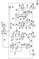
- Fig. 1 shows a schematic representation of a first embodiment of the brake system.
- FIG. 1 schematically illustrated brake system has a master cylinder 10 and an additional brake fluid reservoir 12.
- the brake fluid reservoir 12 may be connected to the master cylinder 10 via at least one hydraulic connection, such as a sniffer bore.
- the brake system has at least one first brake circuit 14 with at least one first wheel brake cylinder 16a and one second wheel brake cylinder 16b.
- the two wheel brake cylinders 16a and 16b of the first brake circuit 14 may be associated with two wheels of a common axle of a vehicle, in particular the rear axle.
- the braking system described here is not limited to an arrangement of the two wheel brake cylinders 16a and 16b of the first brake circuit 14 associated wheels on a common axis of a vehicle.
- the wheels associated with the two wheel brake cylinders 16a and 16b of the first brake circuit can also be arranged on one side or diagonally on the vehicle.
- the first wheel brake cylinder 16a is preferably connected to a branch point 20 via a first output line 18a.
- the second wheel brake cylinder 16b may also be connected to the branch point 20 via a second output line 18b.
- the brake system described here is not limited to such a connection of the two wheel brake cylinders 16a and 16b of the first brake circuit 14.
- the first brake circuit 14 also has an isolation valve 22, which is connected to the master cylinder 10 in such a way that a first brake fluid volume can be transferred from the master brake cylinder 10 via the at least partially opened isolation valve 22 (respectively) into the first wheel brake cylinder 16a and into the second wheel brake cylinder 16b , However, a brake medium displacement from the master cylinder 10 into the first wheel brake cylinder 16a and into the second wheel brake cylinder 16b can be prevented by means of a closing of the isolation valve 22.
- the isolation valve 22 may be connected, for example via a supply line 24 to the master cylinder 10.
- the isolation valve 22 may be connected via a first connecting line 26 to the branching point 20.
- the first brake circuit 14 also includes a first pump 28, by means of which after closing the isolation valve 22 at least in a first mode of the first brake circuit 14, a second brake fluid volume from the brake fluid reservoir 12 (respectively) in the first wheel brake cylinder 16a and in the second wheel brake cylinder 16b pumpable is.
- a first pump 28 by means of which after closing the isolation valve 22 at least in a first mode of the first brake circuit 14, a second brake fluid volume from the brake fluid reservoir 12 (respectively) in the first wheel brake cylinder 16a and in the second wheel brake cylinder 16b pumpable is.
- the first pump 28 is designed as a self-priming pump.
- the first brake circuit 14 has a pump control valve 32, by means of which the first brake circuit 14 at least after closing the isolation valve 22 via a closing of the pump control valve from the first mode is controlled in the second mode, in which despite a drive of the first pump 28 a Brake medium displacement from the brake fluid reservoir 12 is prevented both in the first wheel brake cylinder 16a and in the second wheel brake cylinder 16b.
- a pump control valve 32 by means of which the first brake circuit 14 at least after closing the isolation valve 22 via a closing of the pump control valve from the first mode is controlled in the second mode, in which despite a drive of the first pump 28 a Brake medium displacement from the brake fluid reservoir 12 is prevented both in the first wheel brake cylinder 16a and in the second wheel brake cylinder 16b.
- the first pump 28 on a shaft 30, which drives at least one further component of the vehicle equipped with the brake system, in particular a component of the brake system. Due to the multi-functionality of the shaft 30 and the motor 31 for operating the shaft 30, at least one further motor with an additional shaft disposed thereon for driving the at least one be saved further component.
- the multi-functionality of the shaft 30 and the motor 31 thus reduces costs and reduces the space requirement on the vehicle.
- the multi-functionality of the shaft 30 and the motor 31 can be realized by means of only one pump control valve.
- the advantageous multifunctionality of the shaft 30 and the motor 31, or the inhibiting the filling of two wheel brake / wheel brake cylinders, is thus realized without the total number of electrically controllable valves of the first brake circuit 14 is significantly increased.
- the first brake circuit 14, which can be decoupled from the master brake cylinder 10 merely has to be equipped with a pump control valve. This saves costs and installation space.
- a total number of electrically controllable valves of a brake system can be realized in this way, which allows the use of a more cost effective control device described below for controlling the electrically controllable valves.
- the first brake circuit 14 may include, for example, a high pressure switching valve 32 disposed in an intake passage between the brake fluid reservoir 12 and the first pump 26.
- a high pressure switching valve 32 disposed in an intake passage between the brake fluid reservoir 12 and the first pump 26.
- the operability of the pump control valve is not limited to this example.
- the first brake circuit 14 may also comprise a continuously adjustable control valve 34.
- a continuously adjustable control valve 34 can be understood to mean a valve which, in addition to a closed and a first open position, can still be controlled at least into a second open position.
- the control valve 34 may be, for example, a steadily adjustable / controllable valve.
- the control valve 34 may be connected via a suction line 36 with the brake fluid reservoir 12 and / or via a second connecting line 38 with a arranged in the first connecting line 26 branch point 40 so that a third braking medium volume (respectively) from the first wheel brake cylinder 16a and from the second Wheel brake cylinder 16b via the at least partially open control valve 34 is transferable into the brake fluid reservoir 12.
- a brake medium displacement from the first wheel brake cylinder 16a and the second wheel brake cylinder 16b in the brake fluid reservoir 12 by means of a closing of the control valve 34 can be prevented.
- the desired brake pressure in the two wheel brake cylinders 16a and 16b can thus be set more accurately or reduced to a desired value.
- the control valve 34 may advantageously be used together with the first pump 28 and the high-pressure switching valve 32 used as a pump control valve.
- the high-pressure switching valve 32 via a formed in the suction line 36 branch point 42 and extending between the branch point 42 and the high-pressure switching valve 32 and line 44 extending between the high-pressure switching valve 32 and a suction side of the first pump 28 line 46 together with the first pump 28 in parallel be arranged to the control valve 34.
- the first brake circuit 14 may have at least one pressure sensor 48, which is connected, for example, via a branch point 50 formed in the first connection line 26.
- a sensor signal of the pressure sensor 48 for example, the brake pressure present in the wheel brake cylinders 16a and 16b can be regulated.
- the setting of the brake pressure in the wheel brake cylinders 16a and 16b of the first brake circuit 14 can be effected, for example, by means of a ⁇ p control of the control valve 34.
- a pressure control of the brake pressure at the first brake circuit 14 associated axis is possible.
- the hydraulic connection of the first brake circuit 14 is thus relatively easy to carry out. Nevertheless, due to the isolation valve 22, a by-wire functionality of the first brake circuit 14 is ensured.
- the first brake circuit 14 is preferably designed as a single-channel, so that a single-channel ABS control is executable, in particular in addition to a (normal) partial braking function and / or blending a generator braking torque.
- the select-low method can advantageously be used, the brake pressure in the two wheel brake cylinders 16a and 16b being adjustable in accordance with the minimum of the two brake pressures specifically preferred for the wheel brake cylinders 16a and 16b ,
- a hill hold function can also be carried out by means of the first brake circuit 14.
- a brake actuator 52 such as a brake pedal
- Other functions for active pressure holding are also executable with the first brake circuit 14.
- a check of the tightness of the first brake circuit 14 can take place via a pressure gradient monitoring during partial braking, or in the case of a corresponding function.
- the tightness of the first brake circuit 14 can also be monitored by an active test.
- the brake system preferably has a brake actuating element 52 which is connected to the master brake cylinder 10 and which is connected to at least one adjustable master cylinder piston of the master brake cylinder 10 such that the at least one master brake cylinder piston is at least partially in at least one internal volume of the master brake cylinder by actuation of the brake operating element 52 10 is adjustable. Due to the advantageous hydraulic system, in particular of the first brake circuit 14, the brake system described here can also be used without a device having a brake booster for reliable braking of the vehicle equipped with it in the case of a standard driver brake force.
- the driver does not have to exert a comparatively high driver braking force on the brake actuating element 52, even when doing without a brake booster, because the brake pressure present in the wheel brake cylinders 16a and 16b can be increased by means of the hydraulic system of the first brake circuit 14.
- the brake operating element 52 is therefore preferably connected to the master brake cylinder piston such that a front brake force applied to the brake operating element 52 can be transmitted to the master brake piston without being reinforced. Thus, the cost of a brake booster can be saved.
- Another advantage is that the driver only needs to fill the wheel brake cylinders 60a and 60b (brake calipers) of the second brake circuit 56 by muscle power. It requires less volume than a conventional standard system. Therefore, a relatively small diameter of the master cylinder 10 can be used, which requires relatively small forces. This additionally improves the ease of use.
- the brake operating member 52 may be, for example, a brake pedal.
- the brake system is not limited to an embodiment of the brake operating member 52 as a brake pedal.
- At least one sensor 54 is connected to the brake actuation element 52 in such a way that a variable with respect to an actuation amount of the actuation of the brake actuation element 52 can be detected by the driver by means of the sensor 54.
- the detectable size / operating strength can be, for example, a driver braking force Driver brake pressure and / or an adjustment of the brake operating member 52, or a component disposed thereon.
- the sensor 54 may, in particular, be a pedal travel sensor, a booster membrane travel sensor or a rod travel sensor.
- the formability of the sensor 54 is not limited to the examples listed here. On the usability of the determined by the sensor size / operating strength will be discussed below.
- the brake system additionally has a second brake circuit 56 hydraulically connected to the master brake cylinder 10 with a second pump 58 and / or at least one third wheel brake cylinder 60a and 60b.
- the second brake circuit 56 has two wheel brake cylinders 60a and 60b, each associated with a wheel inlet valve 62a and 62b and one wheel outlet valve 64a and 64b, respectively.
- a supply line 66 connects the master cylinder 10 with a branch point 68, with which the two Radeinlassventile 62 a and 62 b via an in each case a line 70 a and 70 b are connected on the input side.
- each wheel inlet valve 62a and 62b is connected via a line 72a or 72b to the associated wheel brake cylinder 60a or 60b.
- a respective branching point 74a or 74b formed in the lines 72a and 72b and a line 76a and 76b extending therefrom each connect a wheel outlet valve 64a or 64b to the associated wheel brake cylinder 60a or 60b.
- each leads a further line 78a and 78b to a common branch point 80, which is connected via a line 82 to a suction side of the second pump 58.
- a return valve 84 may be arranged, which prevents a brake medium displacement from the second pump 58 via the line 82 to the branching point 80.
- a storage chamber 88 can be connected to the line 82 via a branching point 86.
- the delivery side of the second pump 58 may be connected via a line 90 to a branching point 92 formed in the supply line 66.
- a pressure sensor 96 can be connected, with which the brake pressure in each of the two wheel brake cylinders 60a and 60b can be regulated.
- a wheel-individual ABS function can thus be carried out in addition to the normal partial braking function.
- the second pump 58 may in particular be arranged together with the first pump 28 on the common shaft 30, which is drivable by means of the motor 31.
- the brake system is shown here as a two-piston system.
- other running systems such as pumps with multiple pistons, asymmetric pumps and / or gear pumps, can be used.
- the brake system ensures the advantageous number of only seven electrically controllable valves 22, 32, 34, 62a, 62b, 64a and 64b, although the first brake circuit 14 is completely decoupled by closing the isolation valve 22 of the master cylinder.
- control device can be used to each electrically controllable valve 22, 32, 34, 62a, 62b, 64a and 64b output a separate control signal, the control device having not more than seven signal outputs for outputting the control signals got to.
- a cost-effective and little space-consuming model can be used for the control device.
- the advantageous models with eight signal outputs for outputting the control signals to each electrically controllable valve 22, 32, 34, 62a, 62b, 64a and 64b can be used.
- control device can additionally be designed to blind a time-varying generator braking torque.
- control device is also adapted to a magnitude provided by the sensor 54 regarding the operation amount of the operation of the brake operating member 52 by a driver of the vehicle and a recuperation amount with respect to a generator brake torque applied to at least one wheel associated with the wheel brake cylinders 16a and 16b receive.
- the control device may define a difference between the driver's braking request known via the magnitude / actuating strength and the generator braking torque / recuperation variable (and possibly the hydraulic braking torque of the second brake circuit 56) and thus a desired pumping quantity of the first pump 28 for establishing one of the difference corresponding brake pressure in the wheel brake cylinders 16a and 16b are derived.
- a desired control valve size of the control valve 34 the applicability of the first pump 28 for building up the differential brake pressure corresponding in the wheel brake cylinders 16a and 16b is switchable.
- the high-pressure switching valve 32 can be opened.
- the desired isolating valve size is during the Verblendens ensure that the driver brakes after closing the isolation valve 22 only in the second brake circuit 56 (directly).
- a separating valve control signal corresponding to the desired separating valve size to the separating valve 22 a control valve control signal corresponding to the desired regulating valve size to the regulating valve 34 and a pump control signal corresponding to the desired pumping quantity to the first pump 28 be provided by means of the control device.
- the continuously adjustable control valve 34 is opened for a deceleration corresponding to the decreasing braking request.
- a closed position of the control valve 34 is advantageous.
- the isolation valve 22 is a normally open valve.
- the brake actuating element 52 When the brake actuating element 52 is not actuated, there is thus a hydraulic connection between the first brake circuit 14 and the master brake cylinder 10, via which a brake medium volume can flow back into the brake fluid reservoir 12. If the functioning of the power supply of the brake system is impaired, the driver can still reliably brake into the first brake circuit 14 by means of a pressure buildup in the master brake cylinder 10 in the preferred normally open configuration of the isolation valve 22. Thus, a reliable braking of the vehicle is still guaranteed.
- the brake system can be built from standard components. Thus, despite the comparatively large number of executable functions and realizable advantages, it can be produced inexpensively.
- Fig. 2 shows a schematic representation of a brake system not included in the invention.
- FIG. 2 schematically illustrated brake system has up to the reproduced as a training example for a pump control valve high pressure switching valve the already described components of the previously described embodiment. A re-description of these components and the advantages guaranteed by them is therefore omitted here.
- This in Fig. 2 reproduced brake system has as a pump control valve arranged in a delivery line between the first pump 26 and the branch point 20 Radeinlassventil 100. Even when using the Radeinlassventils 100 as (single) pump control valve, the advantages already mentioned above are guaranteed.
- the first brake circuit 14 also has a wheel outlet valve 102.
- the wheel inlet valve 100 and the wheel outlet valve 102 can thus also be used (in addition to the first pump 28 and the control valve 34) in this embodiment.
- the wheel outlet valve 102 may be connected via a line 104 to a branch point 106 formed in the second output line 18b and via a line 108 to a branch point 110 formed in a line 112 extending parallel to the first pump 28 and the control valve 34.
- the hydraulic connections for the wheel inlet valve 100 and the wheel outlet valve 102 described here are only to be understood as examples.
- the control valve 34 is at least partially opened.
- the utility of the wheel inlet valve 100 as a pump control valve is not limited to this procedure.
- the first brake circuit 14 is a single-channel, so that a single-channel ABS control is executable, preferably in addition to a (normal partial braking function) and / or already described above blending a generator braking torque according to the driver's braking request.
- the reduction of the conventional number of valves for preventing an increase in the brake pressure in the two wheel brake cylinders 16a and 16b despite driving the first pump 28 to the (single) pump control valve has a cost-reducing effect, since control devices with only eight control signal outputs are much cheaper than available control devices with a number of at least nine control signal outputs.
- the brake systems described in the above paragraphs can be used not only in an electric and in a hybrid vehicle, but also in other vehicle types.
- the vehicle is designed with such a braking system for a maximum speed less than 100 km / h, preferably less than 80 km / h, in particular less than 60 km / h.
- the cost-effective and little space-requiring braking systems are advantageously used, since they can perform all the functions required for this type of vehicle.
- they ensure the advantage of not noticeable to the driver veneering with energy production by means of a generator, whereby the fuel consumption can be reduced and these vehicles are also equipped with a smaller battery.
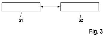
- Fig. 3 shows a flowchart of a method not embraced by the invention for operating the brake system.
- That in the flowchart of Fig. 3 schematically reproduced method is executable with a brake system having a master cylinder, a brake fluid reservoir and at least one brake circuit with at least a first wheel brake cylinder, a second wheel brake cylinder, a separating valve, wherein a brake fluid displacement from the master cylinder in the first wheel brake cylinder and in the second wheel brake cylinder by closing the Separating valve is prevented, and a pump for pumping a brake fluid volume from the brake fluid reservoir (each) in the first wheel brake cylinder and the second wheel brake cylinder comprises.
- the method can be carried out by means of the braking systems described above. The However, the feasibility of the method is not limited to the brake systems described above.
- a method step S1 at least one vehicle component arranged on the common shaft with the pump is driven by means of a motor of the pump.
- the at least one vehicle component may in particular be a component of the brake system, such as a further pump of an additional brake circuit.
- a pump control valve is closed in the method step S1, through which a brake fluid from the brake medium reservoir both in the first wheel brake cylinder and in the second wheel brake cylinder (despite the co-drive of the pump) is prevented.
- Advantageous attachment positions and training examples of the pump control valve are already described above.
- a method step S2 the pump is driven by means of the motor.
- the pump control valve is opened, so that the (presettable) brake fluid volume from the brake medium reservoir (respectively) is pumped into the first wheel brake cylinder and the second wheel brake cylinder by means of the driven pump.
- the method steps S1 and S2 can be carried out in any temporal order directly repeating and / or alternating.
Landscapes
- Engineering & Computer Science (AREA)
- Transportation (AREA)
- Mechanical Engineering (AREA)
- Physics & Mathematics (AREA)
- Fluid Mechanics (AREA)
- Regulating Braking Force (AREA)
Claims (7)
- Système de freinage pour un véhicule avec :un maître-cylindre de frein (10) et un réservoir d'agent de freinage (12) ; etau moins un premier circuit de freinage (14) avec :au moins un premier cylindre de frein de roue (16a) et un deuxième cylindre de frein de roue (16b) ;une soupape de séparation (22) reliée de telle sorte au maître-cylindre de frein (10) qu'un premier volume d'agent de freinage peut être transféré du maître-cylindre de frein (10) à une première conduite de liaison (26) raccordée, via la soupape de séparation (22) au moins en partie ouverte, et au premier cylindre de frein de roue (16a) et au deuxième cylindre de frein de roue (16b) via la première conduite de liaison (26), un déplacement d'agent de freinage du maître-cylindre de frein (10) jusque dans le premier cylindre de frein de roue (16a) et dans le deuxième cylindre de frein de roue (16b) pouvant être entravé en fermant la soupape de séparation (22) ;une première pompe (28) à l'aide de laquelle après la fermeture de la soupape de séparation (22), au moins dans un premier mode du premier circuit de freinage (14), un deuxième volume d'agent de freinage peut être pompé du réservoir d'agent de freinage (12) jusque dans le premier cylindre de frein de roue (16a) et le deuxième cylindre de frein de roue (16b) ; etune soupape de régulation (34) réglable en continu reliée au réservoir d'agent de freinage (12) via une conduite d'aspiration (36) et à un point de ramification (40) réalisé dans la première conduite de liaison (26) via une deuxième conduite de liaison (38) de telle sorte qu'un troisième volume d'agent de freinage peut être transféré du premier cylindre de frein de roue (16a) et du deuxième cylindre de frein de roue (16b) au réservoir d'agent de freinage (12) via la soupape de régulation (34) au moins en partie ouverte et qu'un déplacement d'agent de freinage du premier cylindre de frein de roue (16a) et du deuxième cylindre de frein de roue (16b) jusque dans le réservoir d'agent de freinage (12) peut être entravé en fermant la soupape de régulation (34) ;le système de freinage comprenant un deuxième circuit de freinage (56) relié de façon hydraulique au maître-cylindre de frein (10) avec une deuxième pompe (58), un troisième cylindre de frein de roue (60a) et un quatrième cylindre de frein de roue (60b) auxquels sont respectivement associées une soupape d'admission de roue (62a, 62b) et respectivement une soupape d'échappement de roue (64a, 64b) ;caractérisé en ce que :le premier circuit de freinage (14) comprend une soupape de commande de pompe (32), le premier circuit de freinage (14) prenant la forme de la soupape de commande de pompe (32) comprenant une soupape de commutation en haute pression (32) disposée dans un passage de conduite d'aspiration prévu entre le réservoir d'agent de freinage (12) et la première pompe (28), le premier circuit de freinage (14) pouvant ainsi être commandé au moins après la fermeture de la soupape de séparation (22) via une fermeture de la soupape de commande de pompe (32) pour passer du premier mode dans un deuxième mode dans lequel malgré un entraînement de la première pompe (28), une extraction d'agent de freinage du réservoir d'agent de freinage (12) tant vers le premier cylindre de frein de roue (16a) que vers le deuxième cylindre de frein de roue (16b) est entravée ; etle système de freinage comprend avec la soupape de séparation (22), la soupape de commutation en haute pression (32), la soupape de régulation (34) réglable en continu, les deux soupapes d'admission de roue (62a, 62b) et les deux soupapes d'échappement de roue (64a, 64b) précisément sept soupapes (22, 32, 34, 62a, 62b, 64a, 64b) pouvant être commutées électriquement au moins dans un état ouvert et dans un état fermé.
- Système de freinage selon la revendication 1, le système de freinage comprenant un dispositif de commande à l'aide duquel un signal de commande propre peut respectivement être envoyé à chaque soupape (22, 32, 34, 62a, 62b, 64a, 64b) du système de freinage pouvant être commutée au moins dans un état ouvert et dans un état fermé, le dispositif de commande comportant précisément sept sorties de signal au niveau desquelles les signaux de commande peuvent être émis.
- Système de freinage selon la revendication 2, le dispositif de commande étant en outre conçu pour recevoir une grandeur mise à disposition par un capteur (54) par rapport à une puissance d'actionnement d'un actionnement d'élément d'actionnement de frein (52) par un conducteur du véhicule et une grandeur de récupération par rapport à un couple de freinage de générateur exercé sur au moins les roues associées au premier cylindre de frein de roue (16a) et au deuxième cylindre de frein de roue (16b), pour déterminer une grandeur de soupape de régulation théorique de la soupape de régulation (34) et une grandeur de pompe théorique de la première pompe (28) en tenant compte de la grandeur reçue et de la grandeur de récupération reçue une grandeur de soupape de séparation théorique de la soupape de séparation (22) et pour mettre à disposition de la soupape de séparation (22) un signal de commande de soupape de séparation correspondant à la grandeur de soupape de séparation théorique, à disposition de la soupape de régulation (34) un signal de commande de soupape de régulation correspondant à la grandeur de soupape de régulation théorique et à disposition de la première pompe (28) un signal de commande de pompe correspondant à la grandeur de pompe théorique.
- Système de freinage selon la revendication 3, l'élément d'actionnement de frein (52) étant relié à au moins un piston de maître-cylindre de frein mobile du maître-cylindre de frein (10) de telle sorte qu'une force de freinage appliquée par le conducteur sur l'élément d'actionnement de frein (52) peut être transmise au piston de maître-cylindre de frein sans être renforcée.
- Système de freinage selon l'une quelconque des revendications précédentes, le système de freinage comprenant un moteur (31) avec un arbre (30) au niveau duquel la première pompe (28) et la deuxième pompe (58) sont disposées.
- Système de freinage selon l'une quelconque des revendications précédentes, le premier circuit de freinage (14) étant entièrement découplé du maître-cylindre de frein (10) après la fermeture de la soupape de séparation (22).
- Véhicule équipé d'un système de freinage selon l'une quelconque des revendications précédentes, le véhicule étant conçu pour une vitesse maximale inférieure à 100 km/h, de préférence inférieure à 80 km/h, notamment inférieure à 60 km/h.
Applications Claiming Priority (2)
| Application Number | Priority Date | Filing Date | Title |
|---|---|---|---|
| DE102011005822A DE102011005822A1 (de) | 2011-03-21 | 2011-03-21 | Bremssysteme und Verfahren zum Betreiben eines Bremssystems für ein Fahrzeug |
| PCT/EP2012/051366 WO2012126652A1 (fr) | 2011-03-21 | 2012-01-27 | Systèmes de freinage et procédé permettant de faire fonctionner un système de freinage d'un véhicule |
Publications (2)
| Publication Number | Publication Date |
|---|---|
| EP2688780A1 EP2688780A1 (fr) | 2014-01-29 |
| EP2688780B1 true EP2688780B1 (fr) | 2016-11-16 |
Family
ID=45833344
Family Applications (1)
| Application Number | Title | Priority Date | Filing Date |
|---|---|---|---|
| EP12708747.6A Active EP2688780B1 (fr) | 2011-03-21 | 2012-01-27 | Système de freinage et véhicule avec un tel système de freinage |
Country Status (6)
| Country | Link |
|---|---|
| EP (1) | EP2688780B1 (fr) |
| KR (1) | KR101948947B1 (fr) |
| CN (1) | CN103429472B (fr) |
| BR (1) | BR112013024078A2 (fr) |
| DE (1) | DE102011005822A1 (fr) |
| WO (1) | WO2012126652A1 (fr) |
Families Citing this family (12)
| Publication number | Priority date | Publication date | Assignee | Title |
|---|---|---|---|---|
| DE102012223714A1 (de) | 2012-12-19 | 2014-06-26 | Robert Bosch Gmbh | Verfahren zum Überprüfen eines Trennventils und Überwachungsvorrichtung für ein Trennventil |
| DE102013200471A1 (de) | 2013-01-15 | 2014-07-17 | Robert Bosch Gmbh | Aggregat für ein hydraulisches Bremssystem, hydraulisches Bremssystem, Steuervorrichtung zum Zusammenwirken mit einem hydraulischen Bremssystem und Verfahren zum Betreiben eines hydraulischen Bremssystems |
| DE102013200465A1 (de) * | 2013-01-15 | 2014-07-17 | Robert Bosch Gmbh | Aggregat für ein hydraulisches Bremssystem, hydraulisches Bremssystem, Steuervorrichtung zum Zusammenwirken mit einem hydraulischen Bremssystem und Verfahren zum Betreiben eines hydraulischen Bremssystems |
| DE102013208036A1 (de) | 2013-05-02 | 2014-11-06 | Robert Bosch Gmbh | Steuervorrichtung für ein hydraulisches Bremssystem eines Fahrzeugs, hydraulisches Bremssystem für ein Fahrzeug und Verfahren zum Betreiben eines hydraulischen Bremssystems eines Fahrzeugs |
| DE102013211600A1 (de) * | 2013-06-20 | 2014-12-24 | Robert Bosch Gmbh | Schlupfgeregelte hydraulische Fahrzeugbremsanlage und Verfahren zur Schlupfregelung |
| DE102013217985A1 (de) | 2013-09-09 | 2015-03-26 | Robert Bosch Gmbh | Befestigungsvorrichtung für eine Scheibenwischvorrichtung |
| DE102014214580A1 (de) | 2014-07-24 | 2016-01-28 | Robert Bosch Gmbh | Befestigungsvorrichtung für eine Scheibenwischvorrichtung |
| DE102016204004A1 (de) | 2016-03-11 | 2017-09-14 | Robert Bosch Gmbh | Bremssystem für ein Fahrzeug und Verfahren zum Betreiben eines Bremssystems eines Fahrzeugs |
| DE102016011140A1 (de) | 2016-09-15 | 2018-03-15 | Daimler Ag | Verfahren zur Ermittlung einer Wasserstoffleckage |
| US10696281B2 (en) | 2017-09-25 | 2020-06-30 | Mando Corporation | Electric brake system and operating method thereof |
| CN109552290B (zh) | 2017-09-25 | 2022-12-23 | 株式会社万都 | 电子制动系统以及工作方法 |
| DE102018212018A1 (de) * | 2018-07-19 | 2020-01-23 | Robert Bosch Gmbh | Verfahren zur Dichtheitsprüfung einer hydraulischen Fahrzeugbremsanlage |
Family Cites Families (9)
| Publication number | Priority date | Publication date | Assignee | Title |
|---|---|---|---|---|
| DE4337133C2 (de) * | 1993-10-30 | 2002-10-02 | Bosch Gmbh Robert | Hydraulische Bremsanlage |
| JP2000142369A (ja) * | 1998-11-16 | 2000-05-23 | Bosch Braking Systems Co Ltd | ブレーキシステム |
| DE10023301A1 (de) * | 1999-06-08 | 2001-01-25 | Continental Teves Ag & Co Ohg | Elektronisch regelbare Bremsanlage |
| EP1151901B1 (fr) * | 1999-10-27 | 2004-05-19 | Sumitomo Electric Industries, Ltd. | Systeme et dispositif de freinage pour vehicule |
| DE10240692A1 (de) * | 2001-12-20 | 2003-07-10 | Continental Teves Ag & Co Ohg | Elektrohydraulische Bremsanlage für Kraftfahrzeuge |
| JP2006111251A (ja) * | 2004-09-15 | 2006-04-27 | Hitachi Ltd | ブレーキ制御装置 |
| DE102004045391A1 (de) * | 2004-09-18 | 2006-03-23 | Robert Bosch Gmbh | Verfahren zur Steuerung oder Regelung eines elektronisch ansteuerbaren, nach dem Rückförderprinzip arbeitenden Fahrzeugbremssystems und elektronisch ansteuerbares, nach dem Rückförderprinzip arbeitendes Fahrzeugbremssystem |
| DE102008004201A1 (de) | 2008-01-14 | 2009-07-16 | Robert Bosch Gmbh | Bremssystem und Verfahren zum Steuern eines Bremssystems |
| DE102009001401A1 (de) * | 2009-03-09 | 2010-09-16 | Robert Bosch Gmbh | Bremssystem, Verfahren zum Betreiben eines Bremssystems und Herstellungsverfahren für ein Bremssystem |
-
2011
- 2011-03-21 DE DE102011005822A patent/DE102011005822A1/de not_active Ceased
-
2012
- 2012-01-27 KR KR1020137024635A patent/KR101948947B1/ko active IP Right Grant
- 2012-01-27 EP EP12708747.6A patent/EP2688780B1/fr active Active
- 2012-01-27 CN CN201280014322.0A patent/CN103429472B/zh active Active
- 2012-01-27 WO PCT/EP2012/051366 patent/WO2012126652A1/fr active Application Filing
- 2012-01-27 BR BR112013024078A patent/BR112013024078A2/pt active Search and Examination
Also Published As
| Publication number | Publication date |
|---|---|
| CN103429472A (zh) | 2013-12-04 |
| CN103429472B (zh) | 2016-10-12 |
| KR101948947B1 (ko) | 2019-02-15 |
| WO2012126652A1 (fr) | 2012-09-27 |
| BR112013024078A2 (pt) | 2016-12-06 |
| KR20140006041A (ko) | 2014-01-15 |
| EP2688780A1 (fr) | 2014-01-29 |
| DE102011005822A1 (de) | 2012-09-27 |
Similar Documents
| Publication | Publication Date | Title |
|---|---|---|
| EP2688780B1 (fr) | Système de freinage et véhicule avec un tel système de freinage | |
| EP2234853B1 (fr) | Système de freinage | |
| EP2539195B1 (fr) | Système de freinage pour véhicule et procédé pour faire fonctionner un système de freinage d'un véhicule | |
| EP2739512B1 (fr) | Dispositif de commande pour une installation de freinage d'un véhicule, installation de freinage d'un véhicule et procédé de fonctionnement de l'installation de freinage d'un véhicule | |
| EP2931572B1 (fr) | Procédé pour faire fonctionner un système de freinage d'un véhicule et dispositif de commande d'un système de freinage d'un véhicule | |
| EP2931576B1 (fr) | Procédé pour faire fonctionner un système de freinage d'un véhicule et dispositif de commande d'un système de freinage d'un véhicule | |
| EP2709884B1 (fr) | Système de freinage régénératif pour véhicule et méthode pour mettre en oeuvre un tel système. | |
| EP2632781B1 (fr) | Système de freinage pour un véhicule | |
| DE102010030921A1 (de) | Bremssystem für ein Fahrzeug und Verfahren zum Betreiben eines Bremssystems eines Fahrzeugs | |
| EP2709882B1 (fr) | Dispositif de commande d'un système de freinage d'un véhicule et procédé de fonctionnement d'un système de freinage d'un véhicule | |
| DE102013206324A1 (de) | Bremssystem für ein Fahrzeug und Verfahren zum Betreiben des Bremssystems | |
| DE102016208529A1 (de) | Bremssystem für ein Fahrzeug und Verfahren zum Betreiben eines Bremssystems eines Fahrzeugs | |
| EP2991868B1 (fr) | Système de freinage hydraulique pour un véhicule et procédé pour faire fonctionner un système de freinage hydraulique d'un véhicule | |
| EP2406112A1 (fr) | Système de freinage, procédé pour faire fonctionner un système de freinage et procédé de fabrication pour un système de freinage | |
| DE102008003664A1 (de) | Bremssystem und Verfahren zum Betreiben eines Bremssystems | |
| WO2012055616A1 (fr) | Dispositif de commande et procédé de fonctionnement d'un système de freinage équipé d'un dispositif d'entraînement et/ou générateur électrique | |
| WO2011104047A1 (fr) | Système de freinage pour véhicule et procédé pour faire fonctionner un système de freinage d'un véhicule | |
| EP2709883B1 (fr) | Dispositif de commande d'un système de freinage d'un véhicule et procédé de fonctionnement d'un système de freinage d'un véhicule | |
| DE102013200471A1 (de) | Aggregat für ein hydraulisches Bremssystem, hydraulisches Bremssystem, Steuervorrichtung zum Zusammenwirken mit einem hydraulischen Bremssystem und Verfahren zum Betreiben eines hydraulischen Bremssystems | |
| DE102010062354A1 (de) | Bremssystem für Kraftfahrzeuge | |
| DE102014213354A1 (de) | Bremssystem für ein Fahrzeug und Verfahren zum Betreiben eines Bremssystems eines Fahrzeugs | |
| WO2013182289A1 (fr) | Procédé permettant de faire fonctionner un système de freinage hydraulique d'un véhicule et dispositif permettant de le commander, système de freinage hydraulique et véhicule en étant équipé | |
| DE102012204271A1 (de) | Bremskraftverstärkersteuervorrichtung für einen elektrisch-steuerbaren Bremskraftverstärker und Modulationsvorrichtung für mindestens eine hydraulische Bremsanlagenkomponente |
Legal Events
| Date | Code | Title | Description |
|---|---|---|---|
| PUAI | Public reference made under article 153(3) epc to a published international application that has entered the european phase |
Free format text: ORIGINAL CODE: 0009012 |
|
| 17P | Request for examination filed |
Effective date: 20131021 |
|
| AK | Designated contracting states |
Kind code of ref document: A1 Designated state(s): AL AT BE BG CH CY CZ DE DK EE ES FI FR GB GR HR HU IE IS IT LI LT LU LV MC MK MT NL NO PL PT RO RS SE SI SK SM TR |
|
| DAX | Request for extension of the european patent (deleted) | ||
| 17Q | First examination report despatched |
Effective date: 20150522 |
|
| GRAP | Despatch of communication of intention to grant a patent |
Free format text: ORIGINAL CODE: EPIDOSNIGR1 |
|
| INTG | Intention to grant announced |
Effective date: 20160303 |
|
| GRAS | Grant fee paid |
Free format text: ORIGINAL CODE: EPIDOSNIGR3 |
|
| GRAA | (expected) grant |
Free format text: ORIGINAL CODE: 0009210 |
|
| AK | Designated contracting states |
Kind code of ref document: B1 Designated state(s): AL AT BE BG CH CY CZ DE DK EE ES FI FR GB GR HR HU IE IS IT LI LT LU LV MC MK MT NL NO PL PT RO RS SE SI SK SM TR |
|
| REG | Reference to a national code |
Ref country code: GB Ref legal event code: FG4D Free format text: NOT ENGLISH |
|
| REG | Reference to a national code |
Ref country code: CH Ref legal event code: EP |
|
| REG | Reference to a national code |
Ref country code: IE Ref legal event code: FG4D Free format text: LANGUAGE OF EP DOCUMENT: GERMAN |
|
| REG | Reference to a national code |
Ref country code: AT Ref legal event code: REF Ref document number: 845596 Country of ref document: AT Kind code of ref document: T Effective date: 20161215 |
|
| REG | Reference to a national code |
Ref country code: DE Ref legal event code: R096 Ref document number: 502012008793 Country of ref document: DE |
|
| REG | Reference to a national code |
Ref country code: FR Ref legal event code: PLFP Year of fee payment: 6 |
|
| PG25 | Lapsed in a contracting state [announced via postgrant information from national office to epo] |
Ref country code: LV Free format text: LAPSE BECAUSE OF FAILURE TO SUBMIT A TRANSLATION OF THE DESCRIPTION OR TO PAY THE FEE WITHIN THE PRESCRIBED TIME-LIMIT Effective date: 20161116 |
|
| REG | Reference to a national code |
Ref country code: NL Ref legal event code: MP Effective date: 20161116 |
|
| REG | Reference to a national code |
Ref country code: LT Ref legal event code: MG4D |
|
| PG25 | Lapsed in a contracting state [announced via postgrant information from national office to epo] |
Ref country code: LT Free format text: LAPSE BECAUSE OF FAILURE TO SUBMIT A TRANSLATION OF THE DESCRIPTION OR TO PAY THE FEE WITHIN THE PRESCRIBED TIME-LIMIT Effective date: 20161116 Ref country code: SE Free format text: LAPSE BECAUSE OF FAILURE TO SUBMIT A TRANSLATION OF THE DESCRIPTION OR TO PAY THE FEE WITHIN THE PRESCRIBED TIME-LIMIT Effective date: 20161116 Ref country code: GR Free format text: LAPSE BECAUSE OF FAILURE TO SUBMIT A TRANSLATION OF THE DESCRIPTION OR TO PAY THE FEE WITHIN THE PRESCRIBED TIME-LIMIT Effective date: 20170217 Ref country code: NL Free format text: LAPSE BECAUSE OF FAILURE TO SUBMIT A TRANSLATION OF THE DESCRIPTION OR TO PAY THE FEE WITHIN THE PRESCRIBED TIME-LIMIT Effective date: 20161116 Ref country code: NO Free format text: LAPSE BECAUSE OF FAILURE TO SUBMIT A TRANSLATION OF THE DESCRIPTION OR TO PAY THE FEE WITHIN THE PRESCRIBED TIME-LIMIT Effective date: 20170216 |
|
| PG25 | Lapsed in a contracting state [announced via postgrant information from national office to epo] |
Ref country code: PL Free format text: LAPSE BECAUSE OF FAILURE TO SUBMIT A TRANSLATION OF THE DESCRIPTION OR TO PAY THE FEE WITHIN THE PRESCRIBED TIME-LIMIT Effective date: 20161116 Ref country code: HR Free format text: LAPSE BECAUSE OF FAILURE TO SUBMIT A TRANSLATION OF THE DESCRIPTION OR TO PAY THE FEE WITHIN THE PRESCRIBED TIME-LIMIT Effective date: 20161116 Ref country code: RS Free format text: LAPSE BECAUSE OF FAILURE TO SUBMIT A TRANSLATION OF THE DESCRIPTION OR TO PAY THE FEE WITHIN THE PRESCRIBED TIME-LIMIT Effective date: 20161116 Ref country code: ES Free format text: LAPSE BECAUSE OF FAILURE TO SUBMIT A TRANSLATION OF THE DESCRIPTION OR TO PAY THE FEE WITHIN THE PRESCRIBED TIME-LIMIT Effective date: 20161116 Ref country code: PT Free format text: LAPSE BECAUSE OF FAILURE TO SUBMIT A TRANSLATION OF THE DESCRIPTION OR TO PAY THE FEE WITHIN THE PRESCRIBED TIME-LIMIT Effective date: 20170316 Ref country code: BE Free format text: LAPSE BECAUSE OF NON-PAYMENT OF DUE FEES Effective date: 20170131 Ref country code: FI Free format text: LAPSE BECAUSE OF FAILURE TO SUBMIT A TRANSLATION OF THE DESCRIPTION OR TO PAY THE FEE WITHIN THE PRESCRIBED TIME-LIMIT Effective date: 20161116 |
|
| PG25 | Lapsed in a contracting state [announced via postgrant information from national office to epo] |
Ref country code: EE Free format text: LAPSE BECAUSE OF FAILURE TO SUBMIT A TRANSLATION OF THE DESCRIPTION OR TO PAY THE FEE WITHIN THE PRESCRIBED TIME-LIMIT Effective date: 20161116 Ref country code: SK Free format text: LAPSE BECAUSE OF FAILURE TO SUBMIT A TRANSLATION OF THE DESCRIPTION OR TO PAY THE FEE WITHIN THE PRESCRIBED TIME-LIMIT Effective date: 20161116 Ref country code: CZ Free format text: LAPSE BECAUSE OF FAILURE TO SUBMIT A TRANSLATION OF THE DESCRIPTION OR TO PAY THE FEE WITHIN THE PRESCRIBED TIME-LIMIT Effective date: 20161116 Ref country code: DK Free format text: LAPSE BECAUSE OF FAILURE TO SUBMIT A TRANSLATION OF THE DESCRIPTION OR TO PAY THE FEE WITHIN THE PRESCRIBED TIME-LIMIT Effective date: 20161116 Ref country code: RO Free format text: LAPSE BECAUSE OF FAILURE TO SUBMIT A TRANSLATION OF THE DESCRIPTION OR TO PAY THE FEE WITHIN THE PRESCRIBED TIME-LIMIT Effective date: 20161116 |
|
| REG | Reference to a national code |
Ref country code: DE Ref legal event code: R097 Ref document number: 502012008793 Country of ref document: DE |
|
| PG25 | Lapsed in a contracting state [announced via postgrant information from national office to epo] |
Ref country code: BG Free format text: LAPSE BECAUSE OF FAILURE TO SUBMIT A TRANSLATION OF THE DESCRIPTION OR TO PAY THE FEE WITHIN THE PRESCRIBED TIME-LIMIT Effective date: 20170216 Ref country code: SM Free format text: LAPSE BECAUSE OF FAILURE TO SUBMIT A TRANSLATION OF THE DESCRIPTION OR TO PAY THE FEE WITHIN THE PRESCRIBED TIME-LIMIT Effective date: 20161116 |
|
| REG | Reference to a national code |
Ref country code: CH Ref legal event code: PL |
|
| PLBE | No opposition filed within time limit |
Free format text: ORIGINAL CODE: 0009261 |
|
| STAA | Information on the status of an ep patent application or granted ep patent |
Free format text: STATUS: NO OPPOSITION FILED WITHIN TIME LIMIT |
|
| PG25 | Lapsed in a contracting state [announced via postgrant information from national office to epo] |
Ref country code: MC Free format text: LAPSE BECAUSE OF FAILURE TO SUBMIT A TRANSLATION OF THE DESCRIPTION OR TO PAY THE FEE WITHIN THE PRESCRIBED TIME-LIMIT Effective date: 20161116 |
|
| 26N | No opposition filed |
Effective date: 20170817 |
|
| GBPC | Gb: european patent ceased through non-payment of renewal fee |
Effective date: 20170216 |
|
| PG25 | Lapsed in a contracting state [announced via postgrant information from national office to epo] |
Ref country code: LI Free format text: LAPSE BECAUSE OF NON-PAYMENT OF DUE FEES Effective date: 20170131 Ref country code: CH Free format text: LAPSE BECAUSE OF NON-PAYMENT OF DUE FEES Effective date: 20170131 |
|
| REG | Reference to a national code |
Ref country code: IE Ref legal event code: MM4A |
|
| PG25 | Lapsed in a contracting state [announced via postgrant information from national office to epo] |
Ref country code: LU Free format text: LAPSE BECAUSE OF NON-PAYMENT OF DUE FEES Effective date: 20170127 Ref country code: SI Free format text: LAPSE BECAUSE OF FAILURE TO SUBMIT A TRANSLATION OF THE DESCRIPTION OR TO PAY THE FEE WITHIN THE PRESCRIBED TIME-LIMIT Effective date: 20161116 |
|
| REG | Reference to a national code |
Ref country code: FR Ref legal event code: PLFP Year of fee payment: 7 |
|
| REG | Reference to a national code |
Ref country code: BE Ref legal event code: MM Effective date: 20170131 |
|
| PG25 | Lapsed in a contracting state [announced via postgrant information from national office to epo] |
Ref country code: GB Free format text: LAPSE BECAUSE OF NON-PAYMENT OF DUE FEES Effective date: 20170216 Ref country code: IE Free format text: LAPSE BECAUSE OF NON-PAYMENT OF DUE FEES Effective date: 20170127 |
|
| REG | Reference to a national code |
Ref country code: AT Ref legal event code: MM01 Ref document number: 845596 Country of ref document: AT Kind code of ref document: T Effective date: 20170127 |
|
| PG25 | Lapsed in a contracting state [announced via postgrant information from national office to epo] |
Ref country code: AT Free format text: LAPSE BECAUSE OF NON-PAYMENT OF DUE FEES Effective date: 20170127 |
|
| PG25 | Lapsed in a contracting state [announced via postgrant information from national office to epo] |
Ref country code: MT Free format text: LAPSE BECAUSE OF FAILURE TO SUBMIT A TRANSLATION OF THE DESCRIPTION OR TO PAY THE FEE WITHIN THE PRESCRIBED TIME-LIMIT Effective date: 20161116 |
|
| PGFP | Annual fee paid to national office [announced via postgrant information from national office to epo] |
Ref country code: NL Payment date: 20190121 Year of fee payment: 12 Ref country code: IT Payment date: 20190121 Year of fee payment: 8 |
|
| PG25 | Lapsed in a contracting state [announced via postgrant information from national office to epo] |
Ref country code: HU Free format text: LAPSE BECAUSE OF FAILURE TO SUBMIT A TRANSLATION OF THE DESCRIPTION OR TO PAY THE FEE WITHIN THE PRESCRIBED TIME-LIMIT; INVALID AB INITIO Effective date: 20120127 |
|
| PG25 | Lapsed in a contracting state [announced via postgrant information from national office to epo] |
Ref country code: CY Free format text: LAPSE BECAUSE OF NON-PAYMENT OF DUE FEES Effective date: 20161116 |
|
| PG25 | Lapsed in a contracting state [announced via postgrant information from national office to epo] |
Ref country code: MK Free format text: LAPSE BECAUSE OF FAILURE TO SUBMIT A TRANSLATION OF THE DESCRIPTION OR TO PAY THE FEE WITHIN THE PRESCRIBED TIME-LIMIT Effective date: 20161116 |
|
| PG25 | Lapsed in a contracting state [announced via postgrant information from national office to epo] |
Ref country code: TR Free format text: LAPSE BECAUSE OF FAILURE TO SUBMIT A TRANSLATION OF THE DESCRIPTION OR TO PAY THE FEE WITHIN THE PRESCRIBED TIME-LIMIT Effective date: 20161116 |
|
| PG25 | Lapsed in a contracting state [announced via postgrant information from national office to epo] |
Ref country code: AL Free format text: LAPSE BECAUSE OF FAILURE TO SUBMIT A TRANSLATION OF THE DESCRIPTION OR TO PAY THE FEE WITHIN THE PRESCRIBED TIME-LIMIT Effective date: 20161116 Ref country code: IS Free format text: LAPSE BECAUSE OF FAILURE TO SUBMIT A TRANSLATION OF THE DESCRIPTION OR TO PAY THE FEE WITHIN THE PRESCRIBED TIME-LIMIT Effective date: 20170316 |
|
| PG25 | Lapsed in a contracting state [announced via postgrant information from national office to epo] |
Ref country code: FR Free format text: LAPSE BECAUSE OF NON-PAYMENT OF DUE FEES Effective date: 20200131 |
|
| PG25 | Lapsed in a contracting state [announced via postgrant information from national office to epo] |
Ref country code: IT Free format text: LAPSE BECAUSE OF NON-PAYMENT OF DUE FEES Effective date: 20200127 |
|
| PGFP | Annual fee paid to national office [announced via postgrant information from national office to epo] |
Ref country code: DE Payment date: 20240322 Year of fee payment: 13 |