EP2688528B1 - Percutaneous implant and ostomy method - Google Patents
Percutaneous implant and ostomy method Download PDFInfo
- Publication number
- EP2688528B1 EP2688528B1 EP12716527.2A EP12716527A EP2688528B1 EP 2688528 B1 EP2688528 B1 EP 2688528B1 EP 12716527 A EP12716527 A EP 12716527A EP 2688528 B1 EP2688528 B1 EP 2688528B1
- Authority
- EP
- European Patent Office
- Prior art keywords
- implant
- ingrowth
- dermal
- tissue
- mesh
- Prior art date
- Legal status (The legal status is an assumption and is not a legal conclusion. Google has not performed a legal analysis and makes no representation as to the accuracy of the status listed.)
- Active
Links
- 239000007943 implant Substances 0.000 title claims description 166
- 238000000034 method Methods 0.000 title description 16
- 230000002500 effect on skin Effects 0.000 claims description 65
- 210000003815 abdominal wall Anatomy 0.000 claims description 29
- 210000004207 dermis Anatomy 0.000 claims description 29
- 238000004873 anchoring Methods 0.000 claims description 27
- 238000007789 sealing Methods 0.000 claims description 10
- 238000002513 implantation Methods 0.000 claims description 6
- 230000013011 mating Effects 0.000 claims description 3
- 230000004323 axial length Effects 0.000 claims description 2
- 210000001519 tissue Anatomy 0.000 description 48
- 210000003491 skin Anatomy 0.000 description 16
- 210000003405 ileum Anatomy 0.000 description 14
- 208000015181 infectious disease Diseases 0.000 description 11
- 210000003205 muscle Anatomy 0.000 description 9
- 210000000577 adipose tissue Anatomy 0.000 description 8
- 210000002615 epidermis Anatomy 0.000 description 6
- 238000007455 ileostomy Methods 0.000 description 6
- 238000003780 insertion Methods 0.000 description 6
- 230000037431 insertion Effects 0.000 description 6
- 230000003187 abdominal effect Effects 0.000 description 5
- RTAQQCXQSZGOHL-UHFFFAOYSA-N Titanium Chemical compound [Ti] RTAQQCXQSZGOHL-UHFFFAOYSA-N 0.000 description 4
- 230000004888 barrier function Effects 0.000 description 4
- 238000011161 development Methods 0.000 description 4
- 230000018109 developmental process Effects 0.000 description 4
- 210000003195 fascia Anatomy 0.000 description 4
- 239000010936 titanium Substances 0.000 description 4
- 229910052719 titanium Inorganic materials 0.000 description 4
- 238000003776 cleavage reaction Methods 0.000 description 3
- 230000035876 healing Effects 0.000 description 3
- 210000000936 intestine Anatomy 0.000 description 3
- 239000000463 material Substances 0.000 description 3
- 206010033675 panniculitis Diseases 0.000 description 3
- 230000007017 scission Effects 0.000 description 3
- PTQOJHUHQGPAFD-UHFFFAOYSA-N 2,5,7-trihydroxy-6-methyl-4-oxo-2-phenyl-3h-chromene-8-carbaldehyde Chemical compound C1C(=O)C2=C(O)C(C)=C(O)C(C=O)=C2OC1(O)C1=CC=CC=C1 PTQOJHUHQGPAFD-UHFFFAOYSA-N 0.000 description 2
- 210000001015 abdomen Anatomy 0.000 description 2
- 238000006243 chemical reaction Methods 0.000 description 2
- 239000003795 chemical substances by application Substances 0.000 description 2
- 238000000576 coating method Methods 0.000 description 2
- 238000002224 dissection Methods 0.000 description 2
- 208000014674 injury Diseases 0.000 description 2
- 238000004519 manufacturing process Methods 0.000 description 2
- 210000000713 mesentery Anatomy 0.000 description 2
- 210000002445 nipple Anatomy 0.000 description 2
- 210000000664 rectum Anatomy 0.000 description 2
- 238000010008 shearing Methods 0.000 description 2
- 238000007920 subcutaneous administration Methods 0.000 description 2
- 238000004381 surface treatment Methods 0.000 description 2
- 230000008733 trauma Effects 0.000 description 2
- 208000035143 Bacterial infection Diseases 0.000 description 1
- 206010005003 Bladder cancer Diseases 0.000 description 1
- OYPRJOBELJOOCE-UHFFFAOYSA-N Calcium Chemical compound [Ca] OYPRJOBELJOOCE-UHFFFAOYSA-N 0.000 description 1
- 206010028851 Necrosis Diseases 0.000 description 1
- 206010028980 Neoplasm Diseases 0.000 description 1
- 239000004743 Polypropylene Substances 0.000 description 1
- 208000007097 Urinary Bladder Neoplasms Diseases 0.000 description 1
- 230000006978 adaptation Effects 0.000 description 1
- 230000002411 adverse Effects 0.000 description 1
- 230000003872 anastomosis Effects 0.000 description 1
- 239000003242 anti bacterial agent Substances 0.000 description 1
- 229910052586 apatite Inorganic materials 0.000 description 1
- 230000001580 bacterial effect Effects 0.000 description 1
- 208000022362 bacterial infectious disease Diseases 0.000 description 1
- 230000008901 benefit Effects 0.000 description 1
- 210000000988 bone and bone Anatomy 0.000 description 1
- 230000008993 bowel inflammation Effects 0.000 description 1
- 229910052791 calcium Inorganic materials 0.000 description 1
- 239000011575 calcium Substances 0.000 description 1
- 201000011510 cancer Diseases 0.000 description 1
- 239000000919 ceramic Substances 0.000 description 1
- 230000001684 chronic effect Effects 0.000 description 1
- 239000011248 coating agent Substances 0.000 description 1
- 210000001072 colon Anatomy 0.000 description 1
- 238000004891 communication Methods 0.000 description 1
- 210000002808 connective tissue Anatomy 0.000 description 1
- 238000005520 cutting process Methods 0.000 description 1
- 230000004064 dysfunction Effects 0.000 description 1
- 210000003608 fece Anatomy 0.000 description 1
- 239000012530 fluid Substances 0.000 description 1
- PCHJSUWPFVWCPO-UHFFFAOYSA-N gold Chemical compound [Au] PCHJSUWPFVWCPO-UHFFFAOYSA-N 0.000 description 1
- 229910052588 hydroxylapatite Inorganic materials 0.000 description 1
- 230000008595 infiltration Effects 0.000 description 1
- 238000001764 infiltration Methods 0.000 description 1
- 239000004615 ingredient Substances 0.000 description 1
- 229910052500 inorganic mineral Inorganic materials 0.000 description 1
- 230000000968 intestinal effect Effects 0.000 description 1
- 238000003698 laser cutting Methods 0.000 description 1
- 230000036210 malignancy Effects 0.000 description 1
- 210000004379 membrane Anatomy 0.000 description 1
- 239000012528 membrane Substances 0.000 description 1
- 229910052751 metal Inorganic materials 0.000 description 1
- 239000002184 metal Substances 0.000 description 1
- 229910044991 metal oxide Inorganic materials 0.000 description 1
- 150000004706 metal oxides Chemical class 0.000 description 1
- 230000005012 migration Effects 0.000 description 1
- 238000013508 migration Methods 0.000 description 1
- 239000011707 mineral Substances 0.000 description 1
- 230000017074 necrotic cell death Effects 0.000 description 1
- 229910000510 noble metal Inorganic materials 0.000 description 1
- VSIIXMUUUJUKCM-UHFFFAOYSA-D pentacalcium;fluoride;triphosphate Chemical compound [F-].[Ca+2].[Ca+2].[Ca+2].[Ca+2].[Ca+2].[O-]P([O-])([O-])=O.[O-]P([O-])([O-])=O.[O-]P([O-])([O-])=O VSIIXMUUUJUKCM-UHFFFAOYSA-D 0.000 description 1
- XYJRXVWERLGGKC-UHFFFAOYSA-D pentacalcium;hydroxide;triphosphate Chemical compound [OH-].[Ca+2].[Ca+2].[Ca+2].[Ca+2].[Ca+2].[O-]P([O-])([O-])=O.[O-]P([O-])([O-])=O.[O-]P([O-])([O-])=O XYJRXVWERLGGKC-UHFFFAOYSA-D 0.000 description 1
- 210000004303 peritoneum Anatomy 0.000 description 1
- 239000004033 plastic Substances 0.000 description 1
- 229920003023 plastic Polymers 0.000 description 1
- -1 polypropylene Polymers 0.000 description 1
- 229920001155 polypropylene Polymers 0.000 description 1
- 238000002360 preparation method Methods 0.000 description 1
- 238000003825 pressing Methods 0.000 description 1
- 238000003892 spreading Methods 0.000 description 1
- 230000007480 spreading Effects 0.000 description 1
- 238000010561 standard procedure Methods 0.000 description 1
- 239000000126 substance Substances 0.000 description 1
- 230000003746 surface roughness Effects 0.000 description 1
- 238000001356 surgical procedure Methods 0.000 description 1
- 230000000451 tissue damage Effects 0.000 description 1
- 231100000827 tissue damage Toxicity 0.000 description 1
- 238000011282 treatment Methods 0.000 description 1
- 210000003932 urinary bladder Anatomy 0.000 description 1
- 201000005112 urinary bladder cancer Diseases 0.000 description 1
- 239000011800 void material Substances 0.000 description 1
- 239000002699 waste material Substances 0.000 description 1
Images


Classifications
-
- A—HUMAN NECESSITIES
- A61—MEDICAL OR VETERINARY SCIENCE; HYGIENE
- A61F—FILTERS IMPLANTABLE INTO BLOOD VESSELS; PROSTHESES; DEVICES PROVIDING PATENCY TO, OR PREVENTING COLLAPSING OF, TUBULAR STRUCTURES OF THE BODY, e.g. STENTS; ORTHOPAEDIC, NURSING OR CONTRACEPTIVE DEVICES; FOMENTATION; TREATMENT OR PROTECTION OF EYES OR EARS; BANDAGES, DRESSINGS OR ABSORBENT PADS; FIRST-AID KITS
- A61F5/00—Orthopaedic methods or devices for non-surgical treatment of bones or joints; Nursing devices; Anti-rape devices
- A61F5/44—Devices worn by the patient for reception of urine, faeces, catamenial or other discharge; Portable urination aids; Colostomy devices
- A61F5/445—Colostomy, ileostomy or urethrostomy devices
- A61F2005/4455—Implantable
Definitions
- the present invention relates to a percutaneous ostomy implant.
- the present description also reveals a surgical method, which may use that implant, preferably for creating a continent reservoir in communication with a percutaneous port.
- Ileostomy and colostomy are common operations which may be necessitated, for example, by malignancy or chronic bowel inflammation.
- the surgery is called an ileostomy if the colon and rectum are removed and a colostomy if the rectum alone is removed.
- an abdominal urostomy is created when the urinary bladder has to be removed due to, for example, bladder cancer.
- a stoma is formed in the abdominal wall to which a bowel segment is connected.
- Ostomy is a generic term for any such procedure where a stoma is created.
- the stoma in most cases has to be connected to a bag to collect bodily waste.
- a reservoir known as a "Kock pouch" from the distal part of the ileum. It is formed in such a way that a nipple valve is created which serves to close the reservoir, whilst allowing it to be drained intermittently by means of a catheter.
- CI continent ileostomy
- IPAA ileopouch anal anastomosis
- a percutaneous ostomy implant comprising a solid-walled cylindrical body and an anchoring section in the form of a circular flange.
- the device was designed to be implanted through the abdominal wall and secured by an anchoring section located below the muscle layer.
- This section comprised inner and outer concentric rings interconnected by S-shaped members in order to provide an axially resilient structure which could absorb shear stresses and consequently reduce the risk of tissue damage. Spaces around the S-shaped members and the provision of numerous apertures in the rings allowed for tissue ingrowth and vascularisation. It was proposed to connect the device to the side of the bowel wall and by providing a removable lid on the cylindrical body a continent ostomy could be provided.
- this implant was disclosed in WO 2007/099500 in which the solid-walled cylindrical body was replaced by an axially outer tubular part spaced from the anchoring section by circumferentially-spaced legs.
- the tubular part penetrated the skin and formed a ring for connection to a bag or lid.
- This implant was designed to receive a bowel section drawn up through it; the spaces between the legs allowed the generation of a tissue bond between the inner part of the abdominal wall and the serosal tissue of the bowel in order to provide a more secure, stable, leak-proof and well-vascularised tissue-implant junction.
- a circumferential ingrowth mesh was additionally provided. This extended along most of the length of the tubular part with an annular gap being provided between it and the tubular part to facilitate growth of serosal tissue through the mesh.
- a cylindrical body formed of two axially-spaced tubular parts.
- the outer tubular part penetrated the skin and provided a connecting ring.
- the inner tubular part was attached to an anchoring flange of the type previously described.
- the two parts were connected together by a "distance means" comprising either radially-spaced legs or a rigid cylindrical ingrowth mesh which allowed for the generation of a tissue bond between the abdominal wall and the bowel.
- a percutaneous ostomy implant comprising a cylindrical part for mounting an external detachable device, a cylindrical ingrowth mesh and a circular flange for anchoring the implant.
- the cylindrical part and circular flange were attached to opposite ends of the ingrowth mesh, with the mesh extending inside the cylindrical part.
- the implant was configured such that when it is implanted in the abdominal wall of a patient, abdominal tissue including the epidermis meets the ingrowth mesh and is able to attach therethrough directly to serosal tissue of a bowel segment inside the implant.
- this implant has been found to be effective in ensuring sound attachment of the serosal tissue to the abdominal tissue, it has a drawback in that it becomes more difficult to ensure a fluid-tight seal between the exterior parts of the implant and the bowel segment. This is because the implant relies upon the bowel segment extending within the cylindrical part and maintaining secure infiltration of serosal tissue through the mesh inside that part to form a good seal to the implant. If the bowel recedes below the cylindrical part, a leakage path may be formed through the mesh, even if the bowel segment and abdominal wall remain integrated and the implant remains secure and free of infection.
- the present invention relates to a percutaneous ostomy implant for implantation into the abdominal wall of a patient according to claim 1.
- an implant comprising: a connecting member for mounting an external detachable device thereto; a first (inner) tubular ingrowth member depending from the connecting member; and a second (outer) tubular ingrowth member depending from the connecting member and being radially outwardly spaced from the first tubular ingrowth member; wherein the first tubular ingrowth member is adapted to receive a bowel segment within it to form a stoma and serosal tissue of that bowel segment may infiltrate the first tubular ingrowth member; and the second tubular member is adapted to abut dermal tissue such that the dermal tissue may infiltrate the second tubular ingrowth member, thereby securing and sealing the ostomy implant to the dermis.
- ingrowth means are provided for dermal and serosal tissue.
- the dermal tissue can be caused to ingrow at a location that ensures good attachment and sealing to the implant and which is independent of the ingrowth means provided for the serosal tissue.
- the implant may be used, for example, in an ileostomy, colostomy or urostomy.
- the connecting member may be any convenient shape, thought it is preferably cylindrical and most preferably a circular-based cylinder so that a round opening is provided for attachment of an external device, such as a bag or lid.
- the term “axial” relates to the axis of the connecting member in the last case, or to the corresponding direction in other cases.
- tubular refers to an open-ended form which preferably, but not necessarily, has a circular base or cross-section. Typically, the sectional shape of the tubular members is similar to that of the connecting member.
- the end of the implant to which the detachable device is connected in use i.e. the axially external end
- the top and the opposite end, i.e. the axially internal end is the bottom.
- the opposite end i.e. the axially internal end
- the term "external detachable device” refers to a detachable device, such as a lid, bag or evacuation device, that is external to the patient. It is recognised that some such devices may comprise at least a portion that is received within the upper axial end of the implant.
- the first and/or second tubular ingrowth member(s) preferably comprise mesh.
- the mesh is most conveniently two-dimensional, though three dimensional structures may be used.
- the implant may be made of any biologically-acceptable material, e.g. plastics, it is preferably formed of commercially pure titanium, preferably ASTM Grade 2 titanium.
- the mesh is preferably laser cut from such titanium.
- the implant may have a surface treatment, such as a grit or a blasted surface and/or an electrochemical treatment to achieve optimum topographical properties, physical and chemical surface characteristics (e.g. surface roughness) etc. It is also possible to apply active surface treatments including specialist surface coatings, e.g. metal/metal-oxide/ceramics, to speed up and/or improve healing, prevent infections, etc.
- active surface treatments including specialist surface coatings, e.g. metal/metal-oxide/ceramics, to speed up and/or improve healing, prevent infections, etc.
- all or part of the implant may be coated with agents facilitating additional protection against infections, e.g. they may be coated with noble metals or other antibacterial agents, or be coated with other organic or inorganic agents facilitating a closer tissue adaptation and sealing.
- An example of a suitable coating is hydroxyapatite (a mineral form of calcium apatite and a major component and an essential ingredient of normal bone and teeth).
- the first tubular ingrowth member preferably extends in the axial direction within the connecting member so that serosal tissue may infiltrate the first tubular ingrowth member within the connecting member. It may therefore be referred to as the 'serosal ingrowth member'.
- a space is preferably provided between the inside of it and the ingrowth member. This may be achieved by providing a radially-inwardly projecting portion of the connecting member to which the serosal member is attached.
- the mesh most preferably is attached to a projecting portion within the connecting member and depends downwardly towards the bottom of the implant.
- the connecting member and the first tubular member are coaxial cylinders.
- the second tubular ingrowth member preferably extends in the axial direction so that at least part of it extends around at least part of the connecting member so that dermal tissue may infiltrate the second tubular ingrowth member around the connecting member. It may therefore be termed the 'dermal ingrowth member'.
- the second tubular ingrowth member is radially spaced from the part of the connecting member around which it extends so that an annular dermal ingrowth space is provided.
- the connecting member and the second tubular member are coaxial cylinders. This arrangement allows the dermis to infiltrate the ingrowth member and form a seal against the outer wall of the connecting member.
- this part of the connecting member provides a barrier against which the dermis will grow. It will prevent ingrowth of the dermis into the serosal tissue of the bowel segment, which provides a barrier to the possible infection path from the epidermis to the bowel segment.
- the secure bond that is enabled prevents downgrowth of epidermis along the cylinder.
- the second tubular ingrowth member preferably comprises a mesh that is differently configured (e.g. finer) than mesh used elsewhere, i.e. it may be optimised for dermal ingrowth.
- a percutaneous ostomy implant for implantation into the abdominal wall of a patient, the implant comprising: a connecting member for mounting an external detachable device thereto; a tubular ingrowth member arranged around the connecting member, wherein the tubular ingrowth member is adapted to abut dermal tissue in use such that the dermal tissue may infiltrate the tubular ingrowth member and form a seal against the adjacent part of the connecting member, thereby securing and sealing the implant to the dermis.
- the implant may have any of the other preferred features described herein.
- the implant further comprises a radially-extending dermal anchor to engage the abdominal wall beneath the dermis, preferably just beneath the dermis, e.g. in the junction between dermis and the underlying fatty tissue.
- this anchor is provided far higher up the implant (i.e. towards the exposed end in use) than the known anchors that are intended to engage with fatty tissue or muscle.
- first and/or second tubular ingrowth members extend axially in both directions from the dermal anchor.
- the dermal anchor will be located in the middle-third of the axial length of the implant.
- the dermal ingrowth member will usually be located immediately or closely above the dermal mesh.
- a dermal anchor is any structure that extends radially from the implant in order to secure the implant in the axial direction relative to the dermis. Thus, it may comprise a flange or series of projections lying generally in an imaginary annulus surrounding the implant.
- the dermal anchor is preferably resilient and preferably also allows the ingrowth of tissue through and/or around it.
- a particularly preferred configuration comprises a series of C-shaped projections arranged circumferentially about the implant.
- the dermal anchor comprises a a rally-extending ingrowth mesh, which may be metallic, as previously described, or polymeric, e.g. polypropylene. It may be rigid or flexible.
- a dermal anchor represents an essential aspect of the invention concept and so, viewed from said aspect, the invention provides a percutaneous ostomy implant for implantation into the abdominal wall of a patient, the implant comprising: a connecting member for mounting an external detachable device thereto, the implant being adapted to receive a bowel segment within it to form a stoma, wherein the implant further comprises a radially-extending dermal anchor to engage the abdominal wall beneath and adjacent to the dermis and wherein said anchor comprises a radially-extending ingrowth mesh.
- the dermal anchor may have any of the forms discussed above. Its function is to reduce relative movement between the dermis and the implant - both lateral and vertical - and to distribute stresses over a wide area.
- an ingrowth member is provided in both axial directions from the dermal anchor, i.e. inwardly and outwardly.
- the implant of this aspect preferably further comprises one or more ingrowth member(s) depending from the connecting member part.
- an ingrowth member is adapted to receive the bowel segment within it to form a stoma so that serosal tissue of that bowel segment may infiltrate the ingrowth member.
- the implant may comprise an ingrowth member adapted to abut dermal tissue such that the dermal tissue may infiltrate at least a part of the ingrowth member, thereby securing and sealing the ostomy implant to the dermis.
- the implant comprises both such ingrowth members, i.e. an inner and an outer ingrowth member.
- the cylindrical ingrowth member(s) preferably extend axially in both directions from the dermal anchor.
- the dermal anchor extends radially from the outer tubular ingrowth member. It is possible for the outer tubular ingrowth member to extend axially only from the connecting member to the dermal anchor (indeed it may entirely overlie the connecting member), so that the dermal anchor is located at the bottom of the ingrowth member.
- the outer tubular ingrowth member comprises a first portion above the dermal anchor for ingrowth of dermis and a second portion below the dermal anchor for ingrowth of sub-dermal tissue (including any relevant tissue layer beneath the dermis, such as fatty tissue, muscle or fascia). As noted above, the first portion may have differently configured, e.g. finer, mesh than the second. This additional layer of ingrowth material provides for a larger ingrowth area for sub-dermal and serosal tissue and hence results in a more secure implant.
- the implant may in itself be sufficient to secure the implant in place.
- the implant may further comprise an anchoring flange for securing the implant in sub-dermal tissue, particularly in fat or muscle, or adjacent the fascia. This may be located at the lower end of the outer tubular ingrowth member.
- the anchoring flange is preferably circular and penetrated by multiple small holes to allow ingrowth of connective tissue. It preferably comprises an axially resilient structure, e.g. formed from inner and outer concentric rings, the inner ring being attached to one end of the cylindrical mesh and the outer ring being connected to the inner ring by a plurality of S-shaped connecting members.
- the inner tubular ingrowth member may conveniently terminate co-planarly with the anchoring flange and be radially inwardly spaced therefrom.
- the inner tubular ingrowth member may extend axially below the outer tubular ingrowth member, e.g., the inner tubular ingrowth member may extend axially below the anchoring flange. This provides still greater security for the implant and specifically for the bowel segment inside the inner mesh.
- the lower part of the inner tubular member it is preferred for the lower part of the inner tubular member to be generally trumpet-shaped, frusto-conical or funnel-shaped such that its lower end has a greater diameter than its upper end. This is to prevent possible trauma to the bowel segment by shearing forces imposed by the end of the tubular member and also to provide more space for the mesentery.
- an ostomy implant comprising a tubular ingrowth member which, in use surrounds a bowel section, wherein the lower part of the tubular member is generally trumpet-shaped, frusto-conical or funnel-shaped such that its lower end has a greater diameter than its upper end.
- the invention provides a percutaneous implant comprising an implant body and a radially-extending dermal anchor to engage the abdominal wall beneath and substantially adjacent to the dermis.
- the dermal anchor is preferably as described above.
- the dermal mesh may also be applied to other types of implant and so viewed from a still further aspect there is provided a percutaneous implant comprising an implant body and a tubular ingrowth member arranged around the implant body wherein the tubular member is adapted to abut dermal tissue in use such that the dermal tissue may infiltrate the tubular ingrowth member and form a seal against the adjacent part of the implant body, thereby securing and sealing the implant to the dermis.
- the dermal mesh is preferably as describe above. In particular it is preferably arranged around and spaced from the implant body as in relation to the connecting member.
- the implant may be an ostomy implant as previously described, but it may be any other sort of percutaneous implant, for example an implant to provide a catheter insertion port.
- the implant body may comprise a tissue-impermeable portion surrounding a void, which may form a passage through the implant.
- the implant may comprise one or more ingrowth members (the dermal mesh may, when appropriate, form part of one of these), for example as described previously and the dermal mesh and dermal anchor may be combined in a single implant.
- a method comprising providing such an implant and implanting it in the body of a patient is also disclosed.
- a method of performing an ostomy comprising the use of an implant as described above.
- a method of performing an ostomy comprising providing an ostomy implant according to any aspect or any preferred form thereof as described above; providing a suitable opening for the implant in the body of a patient; implanting the implant in the opening and drawing a bowel segment into the implant to provide a stoma.
- the method is most preferably as described in more detail below.
- the ostomy implant of the invention allows a continent ostomy to be provided because the natural resilience of the vessel tissue (which is constricted to some extent where it is drawn into the implant) occludes the aperture through the implant and results in a valve being formed.
- a reservoir is formed so that fluid pressure is restricted, the valve enables the ostomy to be continent. It may be drained using a catheter in the known manner, or some other evacuation system may be used.
- a lid is preferably provided to provide further protection against leakage and to protect the exposed vessel.
- the present description also reveals a method of performing a continent ostomy comprising: implanting a percutaneous ostomy implant according to any aspect or any preferred form thereof as described above in the abdomen; drawing a section of vessel (e.g. bowel) into the implant; and securing it to form a stoma; wherein the internal diameter of the implant is selected to constrict the vessel such that the natural resilience of the vessel tissue resiliently occludes the stoma, thereby forming a valve.
- the implant and/or method are preferably as set out herein.
- a method of manufacturing such an implant comprises the step of dimensioning the implant for a given patient or class of patients such that a valve will be formed when the implant is used in such method.
- the method of manufacture is preferably as set out herein.
- the implant is preferably used or provided in combination with a lid to prevent leakage and/or to protect the stoma. However, it may also be used in combination with a bag or an evacuation device.
- the invention provides an ostomy implant according to any aspect or preferred from described herein, in combination with a mating lid, bag or evacuation device.
- Mating is typically by means of a part of the lid, bag or evacuation device having a part that in use engages with the connecting member of the implant and preferably connects thereto by means of an engagement means, such as a circumferential groove, around the circumference of the connecting member of the implant.
- an engagement means such as a circumferential groove
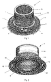
- a first embodiment 1 of an implant comprises four components: a circular anchoring flange 2, an outer mesh cylinder 3a, an inner mesh cylinder 3b and a cylindrical end part 4. These components are each formed separately from machined titanium, with the mesh cylinders 3a, 3b being formed by laser cutting. The individual components are then laser-welded together.
- the end part 4 is in the form of a connection ring. It has a circumferential groove 9 on its outer surface to allow for the connection of detachable devices such as lids, bags, etc.
- the outer mesh cylinder 3a is attached to the outer surface of the end part 4 and the inner mesh cylinder is attached to its inner surface. Both mesh cylinders 3a, 3b depend downwardly (as shown) from end part 4, with the anchoring flange 2 being attached to a termination ring 15 at the lowermost end of the outer cylinder 3a.
- the outer mesh cylinder 3a depends from a radially outwardly projecting part 4a of the end part 4 such that it is spaced radially from the lower part thereof to leave an annular tissue ingrowth space 11.
- the inner mesh cylinder 3b depends from a radially inwardly projecting part 4b of the end part 4 to provide a further annular tissue ingrowth space 12.
- the anchoring flange 2 is as described in the applicant's earlier patent applications referred to in the introduction. It has concentric inner and outer rings 5, 6 connected by S-shaped members 7 to form an axially resilient structure. A multitude of holes 8 are provided to allow ingrowth of tissue through the rings. Only the inner ring 5 of the anchoring flange 2 is connected to termination ring 15 at the end of the outer cylindrical mesh 3a so that the resilient structure allows a degree of play between the outer mesh cylinder 3a and the outer ring 6 of the anchoring flange. There is no connection to the inner cylindrical mesh 3b.
- this embodiment is additionally provided with dermal anchor 13.
- dermal anchor 13 This is mounted to the outside of the outer mesh cylinder 3b. It comprises a series of C-shaped radial projections arranged around the mesh surface.
- outer mesh cylinder 3b has a finer mesh size above the dermal anchor 13 than below it. This finer mesh is designed to facilitate optimum ingrowth of the dermis.
- the mesh below the dermal anchor 13, i.e. the sub-dermal mesh extends at least 6mm in the axial direction to provide a barrier against any infection spreading down subdermally.
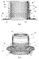
- a second embodiment 20 is shown in Figures 4 to 6 .
- the second embodiment differs from the first embodiment in that its inner mesh cylinder 3a is elongated. As may most clearly be seen from Figures 5 and 6 , it extends through the centre of the anchoring flange 2 into a trumpet-shaped lower portion 21. This has a termination ring 14 with a diameter similar to that of the outer mesh 3a which is above it.
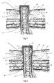
- Figures 7 and 8 show the first and second embodiments 1, 20 of the invention respectively implanted into the abdominal wall 22 of a patient after healing and ingrowth of tissue has taken place.
- the abdominal wall comprises the epidermis 23 and dermis 24, fat layer 25 and muscle layers 26.
- the implant 1, 20 has been implanted in a generally cylindrical opening formed in the abdominal wall formed in a manner that will be discussed in more detail below.
- the anchoring flange 3 is located in an annular incision within the fat layer 25 and the dermal anchor 13 is located in a further annular incision just beneath the dermis 24.
- the ileum has been drawn up inside inner mesh cylinder 3b.
- the dermal anchor is designed to be located in the junction between dermis and the underlying fatty tissue (about 5-8 mm beneath the surface of the skin). It ensures that the implant remains in the correct position in relation to the dermis so that the dermis abuts the upper portion of the outer mesh cylinder 3a. This prevents skin downgrowth and enables it to grow through the fine mesh and into ingrowth space 12 so that it comes into contact with the lower part of the end portion 4. Thus, the end portion 4 is sealed against the skin to provide an infection barrier and to prevent a possible leakage path in the event that the ileum recedes within the implant.
- the dermal anchor 13 assists in maintaining this condition.
- the purpose of the dermal anchor is also to reduce the lateral stresses posed on the outer mesh ingrowth area.
- the fatty tissue also grows through the openings and holes 8 in the anchoring flange 2 in the known manner. This ingrowth provides for secure attachment between the abdominal wall and the ileum and also holds the implant securely in place.
- a double-mesh structure allows for more extensive ingrowth and hence more secure attachment than the prior single mesh implants.
- it also provides a significant advantage in terms of reducing the risk of infection. This is because, except at the top of the end part 4, these components are not contiguous and so there is no infection path between the outer mesh 3a, and inner mesh 3b, which is in contact with the ileum. This is important because the outer mesh 3a extends through the epidermis and is therefore exposed to possible sources of infection. This arrangement means that there is no direct infection path from the skin to the ileum. Also the stresses on the tissue (ingrowth area/sealing area) between the meshes are reduced and is "spread out"/distributed in a advantageous manner due to the surrounding mesh structures.
- the extended portion 21 of the inner mesh 3b provided in the second embodiment ( Figure 8 ) enables a longer portion of the ileum to be encircled by the implant. This enables a greater degree of tissue ingrowth into the implant. Its trumpet shape results in its termination ring being radially displaced from the ileum, which reduces the risk of shearing or tearing trauma being caused to the ileum by the end of the inner mesh and also to provide more space for the mesentery.
- the connecting ring formed by the end portion 4 may be used for the mounting of a suitable bag.
- the implant may be used to provide a continent system. Over a period of time, the section of bowel adjacent the implant will tend to enlarge so that a reservoir or "pouch" is formed, or a reservoir can be constructed at implantation of the implant or an "old" reservoir can be used.
- the stoma may be emptied at intervals using a catheter.
- a removable lid (not shown) may additionally be provided to prevent leakage and to protect the stoma. In this case there is no need for a bag.
- the implant is implanted into the patient in a similar manner to that described in the applicant's earlier patent applications WO 2007/099500 , WO 2009/024568 and WO 2010/000851 , although those techniques are modified to some extent in view of the improvements provided by the invention.
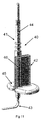
- a specially designed two-part insertion instrument 30 31 is used for facilitated positioning of the implant 1, 20 in the abdominal wall 22.
- the first part 30 has a conical upper part 32 and a lower cylindrical part 33. The latter fits snugly around the end portion 4 of the implant 1, 20 and the former is designed to be pushed through a resilient opening in the abdominal wall.
- the second part 31 has a bowl-shaped body 34 and a handle 35. The body 34 is configured to fit around the anchoring flange 2.
- the two parts of the instrument 30, 31 Prior to implanting the implant 1, 20, the two parts of the instrument 30, 31 are fitted around the respective ends of the implant. The implant may then be inserted through the abdominal wall, with the conical upper 30 part facilitating insertion, whilst it is manipulated using handle 35. Once the implant is in place, the parts of the instrument may then be withdrawn.
- FIGS 11 , 12 and 13 show a specialist diathermy tool to assist in forming a suitable annular incision.
- the tool 40 comprises a conventional diathermy tool 41 in combination with a snap-fit handle 42 and modified cutter 43.
- the tool 42 has a handle 44 at the upper end as shown and is arranged to receive a single-use cutter 43 at its lower end.
- the cutter 43 is modified in that it is bent into an L-shape by means of a suitable jig. This has been found not to adversely affect operation of the cutter.
- Snap-fit handle 42 fits around the tool handle 44 and snaps into place. It has a main body 46 which is formed integrally with locating flange 45. This extends in a plane which is perpendicular to the tool handle axis and hence parallel to the end of the L-shaped cutter 43. Thus, if the flange 45 is placed on and moved over a surface, the cutter will move in a plane parallel to, and a fixed distance below, that surface. In the context of the present invention, that surface is the skin of a patient and so the tool may be used to cut an incision for the anchoring flange of an implant at the correct depth. To achieve this, the cutter 43 is inserted into an incision and the tool is then moved around the circumference of the incision with the cutter oriented in a radially-outward direction.
- the first step is to prepare the patient to receive the implant. to do this, a suitable abdominal incision, e.g., a midline 100-120 mm abdominal incision, is made.
- a suitable abdominal incision e.g., a midline 100-120 mm abdominal incision
- the bowel is prepared in order to make a stoma is according to standard procedures. When this has been done, the size of intestine and abdominal wall are checked and a suitable height and diameter implant is selected. The bowel segment is then inserted into a dummy implant of the selected diameter to make sure there is enough room for a catheter to pass through the implant and that the entry is atraumatic.
- the second step is the preparation for the placement of the port.
- atraumatic dissection from the midline a pocket is created above the external fascia so that the space is sufficient to place the Port.
- the location of the stoma is marked on the abdominal wall preoperatively.
- a small circular hole is then made in the skin where the stoma / implant should be placed.
- a passageway through the subcutis is made by blunt dissection and then, using the diathermy tool describe above, a cleavage is made in the subcutaneous layer for the anchoring flange 2.
- Electrocautery or a scalpel is used to make a cleavage in the dermis/subcutis junction for the dermal anchor.
- Step three is the placement of the implant.
- the implant is fitted to the insertion instrument 30, 31.
- the assembly is inserted into the pocket above the fascia. It is pushed through the subcutis and the cone is driven against the hole in the skin.
- the opening in the skin is customised by cutting against the cone while pressing the Port-Inserter assembly against the opening.
- the aperture should be circular and not too large, so that he skin will tighten well to the cylinder top, but without risk of necrosis.
- the insertion instrument is then withdrawn and the anchoring flange is located in the cleavage previously created in the subcutaneous layer. A check is then made that the port is not inclined and that the skin fits tightly around the implant. If necessary sutures may be used to ensure that the skin fits tightly around the implant.
- Step four is to create the stoma. This is done by making a channel for the stoma through the muscle layer and peritoneal membrane. The distal ileum segment is then inserted through the abdominal wall and the implant. The efferent bowel end is everted ( ad modum Turnbull) (10-20 mm) above the Port and the efferent everted distal end of the stoma is pulled down against the top of the Port. A check is then made to ensure that the intestine is in contact with the implant mesh and the space is filled with intestinal tissue before anchoring the intestine to the peritoneum with sutures.
- ad modum Turnbull 10-20 mm
- step five is to ensure passage. It is important to make sure there is enough room for faeces to pass through the implant. If not, the port should be replaced with one of a larger diameter. In addition, it is important that there is enough room for a catheter to pass through the implant and that the entry is atraumatic. Again, if this is not possible, a larger port is required.
- step six is to close the abdomen according to the normal procedure.
- a catheter is used to drain the pouch whilst healing and tissue ingrowth takes place.
- the serosal tissue of the ileum grows through the mesh layers of the implant into contiguity with the fatty tissue of the abdominal wall and the dermis spreads through outer mesh 3a into ingrowth space 12.
- Any protruding part of the ileum may then be removed and, after a suitable further interval, the catheter may be withdrawn leaving a continent ostomy.
- a lid or bag, or other evacuation system
- end part 4 by means of circumferential groove 9 in the known manner.
Priority Applications (3)
| Application Number | Priority Date | Filing Date | Title |
|---|---|---|---|
| SI201230660A SI2688528T1 (sl) | 2011-03-25 | 2012-03-26 | Perkutani vsadek in metoda ostomije |
| RS20160559A RS55097B1 (sr) | 2011-03-25 | 2012-03-26 | Perkutani implant i postupak ostomije |
| HRP20160782TT HRP20160782T1 (hr) | 2011-03-25 | 2016-07-04 | Perkutani implantat i metoda ostomije |
Applications Claiming Priority (2)
| Application Number | Priority Date | Filing Date | Title |
|---|---|---|---|
| GBGB1105126.5A GB201105126D0 (en) | 2011-03-25 | 2011-03-25 | Percutaneous implant and ostomy method |
| PCT/GB2012/050668 WO2012131351A2 (en) | 2011-03-25 | 2012-03-26 | Percutaneous implant and ostomy method |
Publications (2)
| Publication Number | Publication Date |
|---|---|
| EP2688528A2 EP2688528A2 (en) | 2014-01-29 |
| EP2688528B1 true EP2688528B1 (en) | 2016-06-29 |
Family
ID=44067440
Family Applications (1)
| Application Number | Title | Priority Date | Filing Date |
|---|---|---|---|
| EP12716527.2A Active EP2688528B1 (en) | 2011-03-25 | 2012-03-26 | Percutaneous implant and ostomy method |
Country Status (20)
| Country | Link |
|---|---|
| US (1) | US9615961B2 (zh) |
| EP (1) | EP2688528B1 (zh) |
| JP (1) | JP5980305B2 (zh) |
| CN (1) | CN103476369B (zh) |
| AU (1) | AU2012235941B2 (zh) |
| BR (1) | BR112013024662A2 (zh) |
| CY (1) | CY1117798T1 (zh) |
| ES (1) | ES2584060T3 (zh) |
| GB (1) | GB201105126D0 (zh) |
| HR (1) | HRP20160782T1 (zh) |
| HU (1) | HUE029696T2 (zh) |
| IL (1) | IL228326B (zh) |
| LT (1) | LT2688528T (zh) |
| PL (1) | PL2688528T3 (zh) |
| PT (1) | PT2688528T (zh) |
| RS (1) | RS55097B1 (zh) |
| RU (1) | RU2602724C2 (zh) |
| SI (1) | SI2688528T1 (zh) |
| SM (1) | SMT201600250B (zh) |
| WO (1) | WO2012131351A2 (zh) |
Families Citing this family (12)
| Publication number | Priority date | Publication date | Assignee | Title |
|---|---|---|---|---|
| GB201105126D0 (en) * | 2011-03-25 | 2011-05-11 | Ostomycure As | Percutaneous implant and ostomy method |
| GB2511825A (en) * | 2013-03-14 | 2014-09-17 | Ostomycure As | Implant |
| WO2014145211A2 (en) * | 2013-03-15 | 2014-09-18 | Griffith Donald | Systems and methods for microbial resistance zones to selectively present prophylactically and therapeutically active agents |
| USD829327S1 (en) * | 2013-04-30 | 2018-09-25 | Ostomycure As | Implant having porous surface structure |
| USD827824S1 (en) * | 2013-04-30 | 2018-09-04 | Ostomycure As | Implant with internal porous surface structure |
| USD752750S1 (en) * | 2013-04-30 | 2016-03-29 | Ostomycure As | Implants |
| EP3119452B1 (en) * | 2014-03-16 | 2020-09-30 | NuPulseCV, Inc. | Skin interface device having a skin attachment device and method to implant same |
| US10086184B2 (en) * | 2014-10-08 | 2018-10-02 | Alfred E. Mann Foundation For Scientific Research | Method of manufacturing percutaneous ports with wire coils |
| US10226612B2 (en) * | 2014-10-08 | 2019-03-12 | Alfred E. Mann Foundation For Scientific Research | Percutaneous ports with wire coils |
| WO2018093956A1 (en) * | 2016-11-15 | 2018-05-24 | Giner, Inc. | Percutaneous gas diffusion device suitable for use with a subcutaneous implant |
| US11771585B2 (en) | 2018-01-19 | 2023-10-03 | Ostovalve, Llc | Devices, systems and methods for regulating flow from a stoma on a patient |
| GB201806045D0 (en) | 2018-04-12 | 2018-05-30 | Ostomycure As | Lid |
Family Cites Families (29)
| Publication number | Priority date | Publication date | Assignee | Title |
|---|---|---|---|---|
| US3663965A (en) | 1970-06-08 | 1972-05-23 | Henry L Lee Jr | Bacteria-resistant percutaneous conduit device |
| US4183357A (en) | 1976-08-02 | 1980-01-15 | Bentley Laboratories, Inc. | Chronic transcutaneous implant assembly for enterostomies |
| US4119100A (en) | 1977-03-18 | 1978-10-10 | John William Stanley Rickett | Surgical device for discharge of faecal matter from the colon |
| US4217664A (en) * | 1979-02-02 | 1980-08-19 | Faso Joseph M | Prosthesis and method for creating a stoma |
| GB2045084B (en) | 1979-03-07 | 1983-08-17 | Dunlop Ltd | Tubular devices |
| IT1154510B (it) | 1981-08-14 | 1987-01-21 | Bentley Lab | Dispositivo connettore impiantabile nel corpo e dispositivo di impiantazione vascolare associabile ad esso |
| SE465910B (sv) * | 1988-01-28 | 1991-11-18 | Jan Axel Svensson | Anordning foer sammankoppling av katetrar i en hudgenomgaang |
| IT1244107B (it) | 1990-09-28 | 1994-07-05 | Costan Spa | Circuito frigorifero perfezionato e relativo metodo di sbrinamento |
| SE9003718D0 (sv) | 1990-11-21 | 1990-11-21 | Dan Lundgren | Implantat med genomgaaende passage |
| DE59207776D1 (de) | 1991-10-31 | 1997-02-06 | Helmut Laser | Verschlusssystem für einen instrumentendurchlass |
| US5269774A (en) | 1992-09-25 | 1993-12-14 | Gray Michael W | Implantive ostomy ring |
| DK170206B1 (da) | 1993-02-22 | 1995-06-19 | Coloplast As | Stomikobling |
| US20040006396A1 (en) | 1993-11-02 | 2004-01-08 | Ricci John L. | Transcutaneous devices having nueral interface |
| US5882341A (en) | 1995-07-07 | 1999-03-16 | Bousquet; Gerald G. | Method of providing a long-lived window through the skin to subcutaneous tissue |
| US20010051794A1 (en) | 1997-03-26 | 2001-12-13 | Gilberto Bestetti | Port body for the administration of drugs |
| EP0991437B1 (en) | 1997-06-25 | 2004-02-25 | Biotap A/S | Intercutaneous implant device |
| IT1307246B1 (it) | 1999-04-16 | 2001-10-30 | Claudio Pier Paolo Zanon | Dispositivo per impianti chirurgici di colostomia. |
| ATE281797T1 (de) | 1999-07-15 | 2004-11-15 | Biotap As | Implantat |
| US6438397B1 (en) | 1999-10-28 | 2002-08-20 | Gerald G. Bosquet | Method and apparatus for analyte detection using intradermally implanted skin port |
| DE10357579B4 (de) | 2003-12-08 | 2006-01-26 | Otto Bock Healthcare Gmbh | Implantat mit einem Hautdurchtrittsabschnitt |
| DE602004025341D1 (de) * | 2004-09-06 | 2010-03-18 | Ostomycure As | Implantat |
| US7935096B2 (en) * | 2004-09-06 | 2011-05-03 | Ostomycure As | Percutaneous implant |
| DK1652497T3 (da) * | 2004-10-27 | 2008-06-23 | Ostomycure As | Adaptor, dæksel og forbindelsesdel til stomiposer |
| EP1825839B1 (en) * | 2006-02-28 | 2011-09-21 | Ostomycure AS | Implant |
| EP2364678B1 (en) | 2007-08-21 | 2012-10-03 | Ostomycure AS | Implant |
| EP2317999A2 (en) | 2008-07-04 | 2011-05-11 | Institut National De La Sante Et De La Recherche Medicale (Inserm) | Methods for modulating angiogenesis via dystrophin dp71 |
| ES2635217T3 (es) | 2009-04-28 | 2017-10-02 | Ostomycure As | Procedimiento de fabricación para implante percutáneo |
| US8852217B2 (en) * | 2010-11-16 | 2014-10-07 | Ethicon Endo-Surgery, Inc. | Implantable injection port with tissue in-growth promoter |
| GB201105126D0 (en) * | 2011-03-25 | 2011-05-11 | Ostomycure As | Percutaneous implant and ostomy method |
-
2011
- 2011-03-25 GB GBGB1105126.5A patent/GB201105126D0/en not_active Ceased
-
2012
- 2012-03-26 PL PL12716527.2T patent/PL2688528T3/pl unknown
- 2012-03-26 HU HUE12716527A patent/HUE029696T2/en unknown
- 2012-03-26 RS RS20160559A patent/RS55097B1/sr unknown
- 2012-03-26 SI SI201230660A patent/SI2688528T1/sl unknown
- 2012-03-26 RU RU2013147630/14A patent/RU2602724C2/ru not_active IP Right Cessation
- 2012-03-26 WO PCT/GB2012/050668 patent/WO2012131351A2/en active Application Filing
- 2012-03-26 US US14/006,647 patent/US9615961B2/en active Active
- 2012-03-26 PT PT127165272T patent/PT2688528T/pt unknown
- 2012-03-26 ES ES12716527.2T patent/ES2584060T3/es active Active
- 2012-03-26 EP EP12716527.2A patent/EP2688528B1/en active Active
- 2012-03-26 JP JP2014500477A patent/JP5980305B2/ja active Active
- 2012-03-26 BR BR112013024662A patent/BR112013024662A2/pt active Search and Examination
- 2012-03-26 CN CN201280015208.XA patent/CN103476369B/zh active Active
- 2012-03-26 AU AU2012235941A patent/AU2012235941B2/en not_active Ceased
- 2012-03-26 LT LTEP12716527.2T patent/LT2688528T/lt unknown
-
2013
- 2013-09-09 IL IL228326A patent/IL228326B/en active IP Right Grant
-
2016
- 2016-07-04 HR HRP20160782TT patent/HRP20160782T1/hr unknown
- 2016-07-19 CY CY20161100702T patent/CY1117798T1/el unknown
- 2016-07-27 SM SM201600250T patent/SMT201600250B/it unknown
Also Published As
| Publication number | Publication date |
|---|---|
| SI2688528T1 (sl) | 2017-01-31 |
| ES2584060T3 (es) | 2016-09-23 |
| PT2688528T (pt) | 2016-08-02 |
| CY1117798T1 (el) | 2017-05-17 |
| EP2688528A2 (en) | 2014-01-29 |
| HRP20160782T1 (hr) | 2016-10-21 |
| PL2688528T3 (pl) | 2016-12-30 |
| AU2012235941B2 (en) | 2016-03-31 |
| IL228326B (en) | 2018-03-29 |
| CN103476369A (zh) | 2013-12-25 |
| SMT201600250B (it) | 2016-11-10 |
| JP5980305B2 (ja) | 2016-08-31 |
| WO2012131351A3 (en) | 2013-01-24 |
| RS55097B1 (sr) | 2016-12-30 |
| US9615961B2 (en) | 2017-04-11 |
| GB201105126D0 (en) | 2011-05-11 |
| AU2012235941A1 (en) | 2013-10-10 |
| BR112013024662A2 (pt) | 2016-12-20 |
| JP2014515654A (ja) | 2014-07-03 |
| CN103476369B (zh) | 2015-11-25 |
| US20140052085A1 (en) | 2014-02-20 |
| LT2688528T (lt) | 2016-09-26 |
| HUE029696T2 (en) | 2017-03-28 |
| WO2012131351A2 (en) | 2012-10-04 |
| RU2013147630A (ru) | 2015-04-27 |
| RU2602724C2 (ru) | 2016-11-20 |
Similar Documents
| Publication | Publication Date | Title |
|---|---|---|
| EP2688528B1 (en) | Percutaneous implant and ostomy method | |
| EP2160162B1 (en) | Implant and method for its manufacture | |
| EP2424473B1 (en) | Manufacturing method for percutaneous implant | |
| US11607335B2 (en) | Implant containing rods | |
| EP0559745B1 (en) | Tissue bondable cystostomy tube |
Legal Events
| Date | Code | Title | Description |
|---|---|---|---|
| PUAI | Public reference made under article 153(3) epc to a published international application that has entered the european phase |
Free format text: ORIGINAL CODE: 0009012 |
|
| 17P | Request for examination filed |
Effective date: 20131002 |
|
| AK | Designated contracting states |
Kind code of ref document: A2 Designated state(s): AL AT BE BG CH CY CZ DE DK EE ES FI FR GB GR HR HU IE IS IT LI LT LU LV MC MK MT NL NO PL PT RO RS SE SI SK SM TR |
|
| DAX | Request for extension of the european patent (deleted) | ||
| GRAP | Despatch of communication of intention to grant a patent |
Free format text: ORIGINAL CODE: EPIDOSNIGR1 |
|
| INTG | Intention to grant announced |
Effective date: 20160127 |
|
| GRAS | Grant fee paid |
Free format text: ORIGINAL CODE: EPIDOSNIGR3 |
|
| GRAA | (expected) grant |
Free format text: ORIGINAL CODE: 0009210 |
|
| AK | Designated contracting states |
Kind code of ref document: B1 Designated state(s): AL AT BE BG CH CY CZ DE DK EE ES FI FR GB GR HR HU IE IS IT LI LT LU LV MC MK MT NL NO PL PT RO RS SE SI SK SM TR |
|
| REG | Reference to a national code |
Ref country code: GB Ref legal event code: FG4D |
|
| REG | Reference to a national code |
Ref country code: CH Ref legal event code: EP |
|
| REG | Reference to a national code |
Ref country code: HR Ref legal event code: TUEP Ref document number: P20160782 Country of ref document: HR |
|
| REG | Reference to a national code |
Ref country code: AT Ref legal event code: REF Ref document number: 808492 Country of ref document: AT Kind code of ref document: T Effective date: 20160715 |
|
| REG | Reference to a national code |
Ref country code: RO Ref legal event code: EPE |
|
| REG | Reference to a national code |
Ref country code: IE Ref legal event code: FG4D |
|
| REG | Reference to a national code |
Ref country code: PT Ref legal event code: SC4A Ref document number: 2688528 Country of ref document: PT Date of ref document: 20160802 Kind code of ref document: T Free format text: AVAILABILITY OF NATIONAL TRANSLATION Effective date: 20160722 |
|
| REG | Reference to a national code |
Ref country code: DK Ref legal event code: T3 Effective date: 20160801 |
|
| REG | Reference to a national code |
Ref country code: DE Ref legal event code: R096 Ref document number: 602012019955 Country of ref document: DE |
|
| REG | Reference to a national code |
Ref country code: SE Ref legal event code: TRGR |
|
| REG | Reference to a national code |
Ref country code: NL Ref legal event code: FP |
|
| REG | Reference to a national code |
Ref country code: ES Ref legal event code: FG2A Ref document number: 2584060 Country of ref document: ES Kind code of ref document: T3 Effective date: 20160923 |
|
| REG | Reference to a national code |
Ref country code: NO Ref legal event code: T2 Effective date: 20160629 |
|
| REG | Reference to a national code |
Ref country code: EE Ref legal event code: FG4A Ref document number: E012262 Country of ref document: EE Effective date: 20160726 |
|
| REG | Reference to a national code |
Ref country code: HR Ref legal event code: T1PR Ref document number: P20160782 Country of ref document: HR |
|
| REG | Reference to a national code |
Ref country code: GR Ref legal event code: EP Ref document number: 20160402110 Country of ref document: GR Effective date: 20161118 |
|
| REG | Reference to a national code |
Ref country code: FR Ref legal event code: PLFP Year of fee payment: 6 |
|
| REG | Reference to a national code |
Ref country code: HU Ref legal event code: AG4A Ref document number: E029696 Country of ref document: HU |
|
| REG | Reference to a national code |
Ref country code: DE Ref legal event code: R097 Ref document number: 602012019955 Country of ref document: DE |
|
| PLBE | No opposition filed within time limit |
Free format text: ORIGINAL CODE: 0009261 |
|
| STAA | Information on the status of an ep patent application or granted ep patent |
Free format text: STATUS: NO OPPOSITION FILED WITHIN TIME LIMIT |
|
| 26N | No opposition filed |
Effective date: 20170330 |
|
| STAA | Information on the status of an ep patent application or granted ep patent |
Free format text: STATUS: NO OPPOSITION FILED WITHIN TIME LIMIT |
|
| REG | Reference to a national code |
Ref country code: EE Ref legal event code: MM4A Ref document number: E012262 Country of ref document: EE Effective date: 20170331 |
|
| REG | Reference to a national code |
Ref country code: LT Ref legal event code: MM4D Effective date: 20170326 |
|
| PG25 | Lapsed in a contracting state [announced via postgrant information from national office to epo] |
Ref country code: MC Free format text: LAPSE BECAUSE OF FAILURE TO SUBMIT A TRANSLATION OF THE DESCRIPTION OR TO PAY THE FEE WITHIN THE PRESCRIBED TIME-LIMIT Effective date: 20160629 Ref country code: LV Free format text: LAPSE BECAUSE OF NON-PAYMENT OF DUE FEES Effective date: 20170326 |
|
| PG25 | Lapsed in a contracting state [announced via postgrant information from national office to epo] |
Ref country code: EE Free format text: LAPSE BECAUSE OF NON-PAYMENT OF DUE FEES Effective date: 20170331 Ref country code: LT Free format text: LAPSE BECAUSE OF NON-PAYMENT OF DUE FEES Effective date: 20170326 Ref country code: LU Free format text: LAPSE BECAUSE OF NON-PAYMENT OF DUE FEES Effective date: 20170326 |
|
| PG25 | Lapsed in a contracting state [announced via postgrant information from national office to epo] |
Ref country code: SM Free format text: LAPSE BECAUSE OF NON-PAYMENT OF DUE FEES Effective date: 20171004 Ref country code: RS Free format text: LAPSE BECAUSE OF NON-PAYMENT OF DUE FEES Effective date: 20171006 |
|
| REG | Reference to a national code |
Ref country code: FR Ref legal event code: PLFP Year of fee payment: 7 |
|
| REG | Reference to a national code |
Ref country code: AT Ref legal event code: UEP Ref document number: 808492 Country of ref document: AT Kind code of ref document: T Effective date: 20160629 |
|
| PG25 | Lapsed in a contracting state [announced via postgrant information from national office to epo] |
Ref country code: MT Free format text: LAPSE BECAUSE OF NON-PAYMENT OF DUE FEES Effective date: 20170326 |
|
| REG | Reference to a national code |
Ref country code: HR Ref legal event code: ODRP Ref document number: P20160782 Country of ref document: HR Payment date: 20190313 Year of fee payment: 8 |
|
| PGFP | Annual fee paid to national office [announced via postgrant information from national office to epo] |
Ref country code: DE Payment date: 20190625 Year of fee payment: 14 Ref country code: RO Payment date: 20190325 Year of fee payment: 8 Ref country code: IE Payment date: 20190319 Year of fee payment: 8 |
|
| PGFP | Annual fee paid to national office [announced via postgrant information from national office to epo] |
Ref country code: TR Payment date: 20190320 Year of fee payment: 8 Ref country code: SI Payment date: 20190321 Year of fee payment: 8 Ref country code: AT Payment date: 20190402 Year of fee payment: 8 |
|
| PGFP | Annual fee paid to national office [announced via postgrant information from national office to epo] |
Ref country code: NL Payment date: 20190329 Year of fee payment: 8 Ref country code: SK Payment date: 20190314 Year of fee payment: 8 |
|
| PGFP | Annual fee paid to national office [announced via postgrant information from national office to epo] |
Ref country code: FI Payment date: 20190401 Year of fee payment: 8 Ref country code: NO Payment date: 20190401 Year of fee payment: 8 Ref country code: ES Payment date: 20190401 Year of fee payment: 8 Ref country code: PT Payment date: 20190318 Year of fee payment: 8 Ref country code: IT Payment date: 20190329 Year of fee payment: 8 |
|
| PGFP | Annual fee paid to national office [announced via postgrant information from national office to epo] |
Ref country code: BG Payment date: 20190401 Year of fee payment: 8 |
|
| PGFP | Annual fee paid to national office [announced via postgrant information from national office to epo] |
Ref country code: CH Payment date: 20190329 Year of fee payment: 8 |
|
| PGFP | Annual fee paid to national office [announced via postgrant information from national office to epo] |
Ref country code: DK Payment date: 20200324 Year of fee payment: 9 Ref country code: PL Payment date: 20200317 Year of fee payment: 9 Ref country code: SE Payment date: 20200324 Year of fee payment: 9 |
|
| PGFP | Annual fee paid to national office [announced via postgrant information from national office to epo] |
Ref country code: BE Payment date: 20200318 Year of fee payment: 9 |
|
| REG | Reference to a national code |
Ref country code: HR Ref legal event code: PBON Ref document number: P20160782 Country of ref document: HR Effective date: 20200326 Ref country code: FI Ref legal event code: MAE |
|
| REG | Reference to a national code |
Ref country code: NO Ref legal event code: MMEP |
|
| PG25 | Lapsed in a contracting state [announced via postgrant information from national office to epo] |
Ref country code: PT Free format text: LAPSE BECAUSE OF NON-PAYMENT OF DUE FEES Effective date: 20200928 Ref country code: CZ Free format text: LAPSE BECAUSE OF NON-PAYMENT OF DUE FEES Effective date: 20200326 Ref country code: FI Free format text: LAPSE BECAUSE OF NON-PAYMENT OF DUE FEES Effective date: 20200326 Ref country code: RO Free format text: LAPSE BECAUSE OF NON-PAYMENT OF DUE FEES Effective date: 20200326 Ref country code: CY Free format text: LAPSE BECAUSE OF NON-PAYMENT OF DUE FEES Effective date: 20200326 |
|
| REG | Reference to a national code |
Ref country code: CH Ref legal event code: PL |
|
| REG | Reference to a national code |
Ref country code: NL Ref legal event code: MM Effective date: 20200401 |
|
| REG | Reference to a national code |
Ref country code: AT Ref legal event code: MM01 Ref document number: 808492 Country of ref document: AT Kind code of ref document: T Effective date: 20200326 |
|
| REG | Reference to a national code |
Ref country code: SK Ref legal event code: MM4A Ref document number: E 21658 Country of ref document: SK Effective date: 20200326 |
|
| PG25 | Lapsed in a contracting state [announced via postgrant information from national office to epo] |
Ref country code: NL Free format text: LAPSE BECAUSE OF NON-PAYMENT OF DUE FEES Effective date: 20200401 |
|
| REG | Reference to a national code |
Ref country code: SI Ref legal event code: KO00 Effective date: 20201113 |
|
| PG25 | Lapsed in a contracting state [announced via postgrant information from national office to epo] |
Ref country code: HU Free format text: LAPSE BECAUSE OF NON-PAYMENT OF DUE FEES Effective date: 20200327 Ref country code: GR Free format text: LAPSE BECAUSE OF NON-PAYMENT OF DUE FEES Effective date: 20201008 Ref country code: AT Free format text: LAPSE BECAUSE OF NON-PAYMENT OF DUE FEES Effective date: 20200326 Ref country code: IE Free format text: LAPSE BECAUSE OF NON-PAYMENT OF DUE FEES Effective date: 20200326 Ref country code: BG Free format text: LAPSE BECAUSE OF NON-PAYMENT OF DUE FEES Effective date: 20201130 Ref country code: HR Free format text: LAPSE BECAUSE OF NON-PAYMENT OF DUE FEES Effective date: 20200326 Ref country code: CH Free format text: LAPSE BECAUSE OF NON-PAYMENT OF DUE FEES Effective date: 20200331 Ref country code: NO Free format text: LAPSE BECAUSE OF NON-PAYMENT OF DUE FEES Effective date: 20200331 Ref country code: LI Free format text: LAPSE BECAUSE OF NON-PAYMENT OF DUE FEES Effective date: 20200331 |
|
| REG | Reference to a national code |
Ref country code: DE Ref legal event code: R082 Ref document number: 602012019955 Country of ref document: DE |
|
| PG25 | Lapsed in a contracting state [announced via postgrant information from national office to epo] |
Ref country code: SI Free format text: LAPSE BECAUSE OF NON-PAYMENT OF DUE FEES Effective date: 20200327 Ref country code: SK Free format text: LAPSE BECAUSE OF NON-PAYMENT OF DUE FEES Effective date: 20200326 |
|
| REG | Reference to a national code |
Ref country code: ES Ref legal event code: FD2A Effective date: 20210809 |
|
| REG | Reference to a national code |
Ref country code: ES Ref legal event code: FD2A Effective date: 20210810 |
|
| REG | Reference to a national code |
Ref country code: DE Ref legal event code: R119 Ref document number: 602012019955 Country of ref document: DE |
|
| PG25 | Lapsed in a contracting state [announced via postgrant information from national office to epo] |
Ref country code: IT Free format text: LAPSE BECAUSE OF NON-PAYMENT OF DUE FEES Effective date: 20200326 |
|
| REG | Reference to a national code |
Ref country code: DK Ref legal event code: EBP Effective date: 20210331 |
|
| REG | Reference to a national code |
Ref country code: BE Ref legal event code: MM Effective date: 20210331 |
|
| PG25 | Lapsed in a contracting state [announced via postgrant information from national office to epo] |
Ref country code: AL Free format text: LAPSE BECAUSE OF NON-PAYMENT OF DUE FEES Effective date: 20181030 Ref country code: DE Free format text: LAPSE BECAUSE OF NON-PAYMENT OF DUE FEES Effective date: 20211001 Ref country code: SE Free format text: LAPSE BECAUSE OF NON-PAYMENT OF DUE FEES Effective date: 20210327 |
|
| PG25 | Lapsed in a contracting state [announced via postgrant information from national office to epo] |
Ref country code: DK Free format text: LAPSE BECAUSE OF NON-PAYMENT OF DUE FEES Effective date: 20210331 |
|
| PG25 | Lapsed in a contracting state [announced via postgrant information from national office to epo] |
Ref country code: TR Free format text: LAPSE BECAUSE OF NON-PAYMENT OF DUE FEES Effective date: 20200326 |
|
| PG25 | Lapsed in a contracting state [announced via postgrant information from national office to epo] |
Ref country code: ES Free format text: LAPSE BECAUSE OF NON-PAYMENT OF DUE FEES Effective date: 20200327 Ref country code: BE Free format text: LAPSE BECAUSE OF NON-PAYMENT OF DUE FEES Effective date: 20210331 |
|
| PGFP | Annual fee paid to national office [announced via postgrant information from national office to epo] |
Ref country code: FR Payment date: 20230315 Year of fee payment: 12 |
|
| P01 | Opt-out of the competence of the unified patent court (upc) registered |
Effective date: 20230517 |
|
| PGFP | Annual fee paid to national office [announced via postgrant information from national office to epo] |
Ref country code: GB Payment date: 20240313 Year of fee payment: 13 |