EP2688436B1 - Flexible shoe sole - Google Patents
Flexible shoe sole Download PDFInfo
- Publication number
- EP2688436B1 EP2688436B1 EP12762931.9A EP12762931A EP2688436B1 EP 2688436 B1 EP2688436 B1 EP 2688436B1 EP 12762931 A EP12762931 A EP 12762931A EP 2688436 B1 EP2688436 B1 EP 2688436B1
- Authority
- EP
- European Patent Office
- Prior art keywords
- sole
- region
- fiber
- fibers
- rigid portion
- Prior art date
- Legal status (The legal status is an assumption and is not a legal conclusion. Google has not performed a legal analysis and makes no representation as to the accuracy of the status listed.)
- Active
Links
Images


Classifications
-
- A—HUMAN NECESSITIES
- A43—FOOTWEAR
- A43B—CHARACTERISTIC FEATURES OF FOOTWEAR; PARTS OF FOOTWEAR
- A43B5/00—Footwear for sporting purposes
- A43B5/14—Shoes for cyclists
-
- A—HUMAN NECESSITIES
- A43—FOOTWEAR
- A43B—CHARACTERISTIC FEATURES OF FOOTWEAR; PARTS OF FOOTWEAR
- A43B13/00—Soles; Sole-and-heel integral units
- A43B13/14—Soles; Sole-and-heel integral units characterised by the constructive form
-
- A—HUMAN NECESSITIES
- A43—FOOTWEAR
- A43B—CHARACTERISTIC FEATURES OF FOOTWEAR; PARTS OF FOOTWEAR
- A43B13/00—Soles; Sole-and-heel integral units
- A43B13/02—Soles; Sole-and-heel integral units characterised by the material
- A43B13/026—Composites, e.g. carbon fibre or aramid fibre; the sole, one or more sole layers or sole part being made of a composite
-
- A—HUMAN NECESSITIES
- A43—FOOTWEAR
- A43B—CHARACTERISTIC FEATURES OF FOOTWEAR; PARTS OF FOOTWEAR
- A43B13/00—Soles; Sole-and-heel integral units
- A43B13/14—Soles; Sole-and-heel integral units characterised by the constructive form
- A43B13/141—Soles; Sole-and-heel integral units characterised by the constructive form with a part of the sole being flexible, e.g. permitting articulation or torsion
Definitions
- US 5406723 A describes a cycling shoe sole comprising a light core, fibrous layers surrounding the core to reinforce the core, and a resin for integrating the fibrous layers and core.
- footwear In addition to providing footwear that meets a wearer's support needs, the footwear needs to provide maximum performance and maintain comfort, efficiently transferring energy and providing flexibility. Furthermore, footwear needs to be lightweight and durable. For example, a bicyclist needs footwear that provides adequate support in the area surrounding the ball of the foot to reduce foot fatigue and provide flexibility both while bicycling and when dismounted from the bicycle. Additionally, the footwear needs to be lightweight and have the ability to flex according to the flexure of the wearer's foot.
- the first portion is positioned in a first region of a composite element, and the second portion is positioned in a second, different region of the composite element.
- the first portion and the second portion are at least partially disposed within the same region of the composite element.
- a composite element comprises a toe region, a forefoot region, an arch region, a heel region, or any combination thereof.
- a composite element includes a first portion having a first rigidity and a second portion having a second rigidity that is different than the first rigidity. The first portion and the second portion of the composite element may be formed in various shapes.
- the first portion and/or the second portion is circular, rectangular, triangular, or u-shaped when viewed from a proximal viewpoint.
- the first portion and/or the second portion may be formed in various sizes.
- the first portion and/or the second portion extend approximately a full width of a sole.
- a more rigid portion extends a partial width of a shoe sole.
- a less rigid portion may surround the sides of the more rigid portion when viewed from a proximal viewpoint.
- the first portion has a different thickness than the second portion.
- the first portion and/or the second portion may be positioned in various regions within a composite element.
- a composite element includes a deformable portion and a substantially non-deformable portion.
- the deformable portion comprises at least one fiber-reinforced layer
- the substantially non-deformable portion comprises at least one fiber-reinforced layer.
- the deformable portion comprises a different number of layers than the substantially non-deformable portion.
- the deformable portion and the substantially non-deformable portion each comprise a plurality of fiber-reinforced layers configured to provide a footwear sole with the desired flexure characteristics according to the characteristics of the wearer and the intended use. The orientation, the shape, the thickness, and/or the number of layers, for example, of each portion may be altered to provide the desired flexure characteristics for that portion of the composite element.
- a composite element has at least one deformable toe region, arch region, and heel region having a first plurality of fiber-reinforced layers, and a substantially non-deformable forefoot region having a second plurality of fiber-reinforced layers.
- the forefoot region generally is positioned between the toe region and the arch region, and the arch region generally is positioned between the forefoot region and the heel region.
- the second plurality of fiber-reinforced layers may have a greater number of layers than the first plurality of fiber-reinforced layers.
- the first and second pluralities of fiber-reinforced layers may form the composite element.
- an outsole may include at least one lug protruding distally from the outsole.
- the lug(s) may be an integral component of the outsole, or, alternatively, the lug(s) may be a separate component attached to the outsole.
- the position and composition of the lug(s) may vary.
- an outsole may include a cleat attachment void, cut or drilled into the outsole to accommodate the attachment of a cleat.
- the method may further comprise molding the composite element with an outsole element to form an outsole, a midsole element to form a midsole, and an innersole element to form an innersole.
- the method may comprise bonding the sole to a shoe upper.
- the term “a” or “an” entity refers to one or more of that entity.
- the terms “a” (or “an”), “one or more” and “at least one” can be used interchangeably herein. It is also to be noted that the terms “comprising”, “including”, and “having” can be used interchangeably.
- each of the expressions “at least one of A, B and C”, “at least one of A, B, or C”, “one or more of A, B, and C", “one or more of A, B, or C" and "A, B, and/or C” means A alone, B alone, C alone, A and B together, A and C together, B and C together, or A, B and C together.
- the term “longitudinal” refers to a direction extending a length of a footwear component.
- the longitudinal direction may extend from a heel region of a footwear component to a toe region of the footwear component.
- the term “lateral” refers to a direction extending a width of a footwear component.
- the term “vertical” refers to a direction generally perpendicular to the longitudinal and the lateral direction.
- proximal refers to a position that is closer to a portion of a foot when an article of footwear is worn.
- distal refers to a position that is further from a portion of a foot when an article of footwear is worn.
- fiber refers to at least one of the following list: single-walled carbon-nanotubes, multi-walled carbon nanotubes, graphene nanoribbons, carbon-fibers, metal fibers, glass fibers, rayon fibers, silk fibers, nylon fibers, olefin fibers, acrylic fibers, polyester fibers, and aramid fibers.
- the term, "innersole” refers to a removable portion of the sole of an article of footwear, which is inserted into the article of footwear from the opening in the upper and which is designed to provide support to the wearer's foot, depending upon the wearer's anatomy and the intended use of the article of footwear.
- lug refers to a protusion either integral to the outsole or attached to the outsole that aids in providing traction for the wearer of an article of footwear.
- midsole refers to that portion of the sole of an article of footwear sandwiched between the innersole and the outsole, to which is attached the outsole.
- outsole refers to that portion of the sole of an article of footwear that is furthest from the upper.
- prepreg layer refers to a layer of polymeric material that has previously been impregnated with fibers.
- Fig. 1 is a side elevation view of an article of footwear, generally referred to as a shoe 2.
- the shoe 2 comprises a shoe upper 6 attached to a sole 10.
- the upper 6 generally encloses the foot and can comprise any upper now known or later developed in the art.
- the sole 10 may include, but is not limited to, an innersole, a midsole, and/or an outsole.
- Figs. 2-14 depict specific embodiments.
- Figs. 2-4 illustrate embodiments of a composite element integrally formed with an outsole element to form an outsole.
- Figs. 5-9 illustrate embodiments of a composite element that may be associated with both left and right forms of a sole designed to fit a man, a woman, or both. Embodiments may be associated with soles having a shoe size according to any international shoe size designation.
- Embodiments may be associated with soles attached to a wide range of athletic footwear, including but not limited to walking shoes, tennis shoes, basketball shoes, cross-training shoes, weightlifting shoes, bicycling shoes, track spikes, soccer shoes, football shoes, roller skates, clap skates and other ice skates, Nordic skiing boots, downhill skiing boots, and snowboard boots, for example.
- embodiments may be associated with soles attached to a wide range of non-athletic footwear, including but not limited to work boots, sandals, loafers, and dress shoes. Accordingly, embodiments of the present invention apply to footwear generally.
- Figs. 10-13 illustrate embodiments of a fiber-reinforced layer(s) that may be utilized to form a composite element.
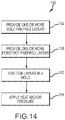
- Figure 14 illustrates one embodiment of a method of manufacturing a composite element.
- the outsole 22 is divided into four general regions: a toe region 26 that generally corresponds with a wearer's toes, a forefoot region 30 that generally corresponds with a wearer's metatarsal bones and the joint between the metatarsal bones and the phalanges, an arch region 34 that generally corresponds with a wearer's foot arch, and a heel region 38 that generally corresponds with a wearer's foot heel.
- the forefoot region 30 is positioned between the toe region 26 and the arch region 34, and the arch region 34 is positioned between the forefoot region 30 and heel region 38.
- the depicted regions are not intended to demarcate precise areas of the composite element 14, the outsole element 18, or the outsole 22. Instead, the regions are intended to define general areas that aid in the following discussion.
- the composite element 14 may be formed as a separate article and connected to the outsole element 18 using known methods of attachment, such as adhesives, molding, stitching, mechanical fasteners, and the like.
- the composite element 14 may be connected to the bottom surface of a midsole such that the composite element 14 is visible and, in some instances, accessible from the bottom of the article of footwear.
- the more rigid portion 42 has a greater thickness than the less rigid portion 46.
- the added thickness generally protrudes distally from the composite element 14.
- the more rigid portion 42 may include a thickness that protrudes proximally from a less rigid portion 46 of the composite element 14 or protrudes proximally and distally from a less rigid portion 46 of the composite element 14.
- a more rigid portion 42 may have the same thickness as a less rigid portion 46.
- the more rigid portion 42 may be substantially rigid and substantially non-deformable.
- the size, shape, and thickness of the regions of the composite element 14 in the less rigid portion 46 of the composite element 14 is adjusted to vary the rigidity of the regions.
- the altered size and shape of the toe region 26 in Fig. 4 provides a different rigidity, including torsional and/or bending, in the toe region 26 as compared to the other regions of the less rigid portion 46 of the composite element 14.
- the less rigid portion 46 may be deformable. In another embodiment, the less rigid portion 46 may be deformable by torsional and/or shear stresses.
- the outsole element 18 may contain one or more lugs 50 extending distally from the outsole element 18.
- the one or more lugs 50 may be an integral component of the outsole element 18, or, alternatively, the one or more lugs 50 may be a separate piece attached to the outsole element 18. Additionally, the position and composition of the one or more lugs 50 may vary depending on the type of footwear that the outsole element 18 will be incorporated into.
- the one or more lugs 50 may be composed of a polymeric material. Additionally, the polymeric material of the one or more lugs 50 may differ from the polymeric material of the outsole element 18 when the one or more lugs is attached to rather than an integral component of the outsole element 18.
- the outsole element 18 is a polymeric material, comprising one or more of a homopolymer, copolymer, polymer alloy or a combination thereof, and wherein the polymeric material comprises one or more of vinyl esters, epoxies, polyolefins, polystyrenes, polyvinyls, polyacrylics, polyhalo-olefins, polydienes, polyoxides, polyesters, polyacetals, polysulfides, polythioesters, polyamides, polythioamides, polyurethanes, polythiourethanes, polyureas, polythioureas, polyimides, polythioimides, polyanhydrides, polythianhydrides, polycarbonates, polythiocarbonates, polyimines, polysiloxanes, polysilanes, polyphosphazenes, polyketones, polythioketones, polysulfones, polysulfoxides, polysulfonates,
- the composite element 14 and the outsole element 18 in Figs. 2-4 can include several cleat attachment voids.
- two slots 54 are provided and adapted to accommodate a bicycle pedal cleat.
- a more rigid portion 42 of the forefoot region provides a stiff interaction point to transfer energy from the outsole 22 to a bicycle pedal.
- a cleat attachment void may be provided in one or both of the toe region 26 and the heel region 38.
- apertures 58 are provided in the toe region 26 and the heel region 38.
- an outsole 22 may include one or more depressed areas surrounding the proximal side of a cleat attachment void.
- the illustrated depressed areas 62 surround the slots 54 formed in the forefoot region 30 and the apertures 58 formed in the toe region 26.
- the depressed area 62 surrounding the slots 54 can be dimensioned to accommodate a bicycling cleat mounting plate, and the depressed area 62 surrounding the apertures 58 can be dimensioned to accommodate mounting plates for other types of cleats.
- the composite element 14 may not include all of the indicated regions. Rather, the composite element 14 may include a toe region 26, a forefoot region 30, an arch region 34, or a heel region 38, individually or in any combination thereof.
- the composite element 14 has a toe region 26, a forefoot region 30, and an arch region 34; however, the composite element 14 does not have a heel region 38.
- the regions may vary in size and shape.
- the toe region 26 is shaped in the form of a strip, rather than the typical curve-shape of a toe portion of a sole. Adjusting the size and shape of the various regions varies the rigidity of the regions. For example, the altered size and shape of the toe region 26 in Fig. 9 allows more torsional and/or bending deformation than the toe region 26 and heel region 38 shown in Fig. 5 .
- Figs. 7-8 illustrate embodiments of a composite element 14 having a more rigid portion 42, which may be substantially rigid and non-deformable, and at least one less rigid portion 46, which may be deformable.
- the more rigid portion 42 is positioned in the forefoot region 30, whereas the less rigid portion 46 is positioned in one or more of the toe region 26, the arch region 34, and the heel region 38.
- the less rigid portion 46 is comprised of at least one fiber-reinforced layer 66 in the toe region 26, the arch region 34, and/or the heel region 38.
- the at least one fiber-reinforced layer 66 of the less rigid portion 46 as depicted in Fig.
- the at least one fiber-reinforced layer 66 of the less rigid portion 46 may have minimal stiffness, thereby increasing the flexibility of the less rigid portion 46 of the composite element 14, as shown in Fig. 8 .
- the at least one fiber-reinforced layer 66 of the less rigid portion 46 may have increased stiffness.
- a more rigid portion 42 of the forefoot region 30 provides maximum energy and/or power transfer while the less rigid portion 46 of the toe region 26, the arch region 34, and the heel region 38 provides flexibility.
- This varying rigidity in various regions of a sole is particularly useful for many athletic and other shoes that need to transfer energy and/or power efficiently and/or need to provide protection and/or comfort to specific areas of a wearer's foot. It can be appreciated that, the number and the stacking configuration, including orientation, of the fiber-reinforced layers 66 and 70, as depicted in Fig. 8 , may be altered as desired.
- the flexure characteristics of composite element 14 may be altered by varying the number of fiber-reinforced layers 66 and 70, the configuration and thickness of each layer 66 and 70, and the orientation of each layer 66 and 70. In this manner, the composite element 14 is adapted to the characteristics of the wearer and the intended use.
- the at least one fiber-reinforced layer 66 has from about one to about four fiber-reinforced layers 66.
- the composite element 14 does not extend to or comprise all regions. Accordingly, at least one of the toe region 26 and the heel region 38 will not have a fiber-reinforced layer.
- each fiber-reinforced layer comprises a resin component and a fiber-containing component.
- the resin component may include one or more of a homopolymer, copolymer, polymer alloy or a combination thereof, and wherein the polymeric material comprises one or more of vinyl esters, epoxies, polyolefins, polystyrenes, polyvinyls, polyacrylics, polyhalo-olefins, polydienes, polyoxides, polyesters, polyacetals, polysulfides, polythioesters, polyamides, polythioamides, polyurethanes, polythiourethanes, polyureas, polythioureas, polyimides, polythioimides, polyanhydrides, polythianhydrides, polycarbonates, polythiocarbonates, polyimines, polysiloxanes, polysilanes
- the fiber-containing component may include single-walled carbon-nanotubes, multi-walled carbon nanotubes, graphene nanoribbons, carbon-fibers, glass fibers, rayon fibers, silk fibers, metal fibers, nylon fibers, olefin fibers, acrylic fibers, polyester fibers, aramid fibers, and combinations thereof.
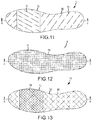
- Fig. 10 illustrates one embodiment of a fiber-reinforced layer 66 having a plurality of fibers 74 randomly oriented with respect to a line A-A.
- the random orientation of the fibers 74 can provide one or both longitudinal and transverse stiffness.
- Fig. 11 illustrates one embodiment of a composite element 14 having at least one fiber-reinforced layer 66 and at least one additional fiber-reinforced layer 70.
- a plurality of fibers 74 within the at least one fiber-reinforced layer 66 is substantially oriented at a first angle with respect to a longitudinal axis A-A that extends from the toe region to the heel region of the composite element 14.
- a plurality of fibers 74 within the at least one additional fiber-reinforced layer 70 is substantially oriented at a second, differing angle with respect to the longitudinal axis A-A.
- each fiber-reinforced layer may have one or both of a different directional flexure characteristic and stiffness.
- the longitudinal and transverse flexure characteristics of the composite element can be tailored for a specific activity in which the human wearer is expected to engage.
- the stiffness of a composite element 14 can be tailored to specific applications by varying the number of the fiber-reinforced layers, as well as the angular orientations of the layers. Further, the flexure characteristics of the at least one fiber-reinforced layer 66 and the at least one additional fiber-reinforced layer 70 may customize the localized regional stiffness to accommodate a specific application. The particular flexure characteristic to be incorporated in any given article of footwear may be tuned to the wearer and/or activity the wearer is to be engaged in.
- the layer(s) of the at least one fiber-reinforced layer 66 is arranged at offsets corresponding to rotations of approximately 10 degrees from the longitudinal axis A-A
- the layer(s) of the at least one additional fiber-reinforced layer 70 is arranged at offsets corresponding to rotations of approximately 45 degrees from the longitudinal axis A-A.
- the fiber-reinforced layers can provide varying degrees of stiffness or alternatively flexibility in a specific region of a sole.
- individual layers 66 and 70 may be oriented from 0 degrees to 180 degrees, in either a clockwise or counterclockwise direction, from the longitudinal axis A-A, depending on the desired flexure characteristics.
- Fig. 12 illustrates one embodiment of a fiber-reinforced layer 66 employing a woven fabric 78.
- the alignment and weave of the woven fabric 78 can provide strength and stiffness properties in certain portions of the composite element 14 and flexibility in other portions of the composite element 14. These variations in strength and stiffness between the portions of the composite element may be accomplished by varying the number of layers of fabric within the fiber-reinforced layer(s), or the orientation of the layers of fabric within the fiber-reinforced layer(s).
- the strength and stiffness properties are about the forefoot region 30 and the flexibility is about one or more of the toe region 26, the arch region 34, and the heel region 38.
- Fig. 13 illustrates embodiments of a composite element 14 having at least one fiber-reinforced layer 66 and at least one additional fiber-reinforced layer 70.
- the fiber-reinforced layers may contain a woven fabric 78 having a bias.
- the woven fabric 78 within the at least one fiber-reinforced layer 66 can be substantially oriented at a first angle with respect to a longitudinal axis A-A.
- the woven fabric 78 within the at least one additional fiber-reinforced layers 70 can be substantially oriented at a second angle with respect to the longitudinal axis A-A.
- the present disclosure in various embodiments, configurations, or aspects, includes components, methods, processes, systems and/or apparatus substantially as depicted and described herein, including various aspects embodiments, configurations, sub-combinations, and subsets thereof. Those of skill in the art will understand how to make and use the various aspects, embodiments, configurations, sub-combinations, and subsets of the present disclosure after understanding the disclosure.
- the present disclosure in various aspects, embodiments, and configurations, includes providing devices and processes in the absence of items not depicted and/or described herein or in various aspects, embodiments, or configurations hereof, including in the absence of such items as may have been used in previous devices or processes, e.g., for improving performance, achieving ease and ⁇ or reducing cost of implementation.
Landscapes
- Chemical & Material Sciences (AREA)
- Engineering & Computer Science (AREA)
- Materials Engineering (AREA)
- Health & Medical Sciences (AREA)
- General Health & Medical Sciences (AREA)
- Physical Education & Sports Medicine (AREA)
- Footwear And Its Accessory, Manufacturing Method And Apparatuses (AREA)
Description
- This disclosure relates generally to a sole for footwear and, more particularly, to a composite element for footwear and a method for making the same.
- People need different amounts of support for their footwear depending on their characteristics, such as weight and gait, and upon the intended use of the footwear. For example, in some situations, such as during cross-training, it may be beneficial to have longitudinal and lateral support in the footwear. Alternatively, in some situations, such as sprinting, it may be beneficial to have longitudinal support, but not lateral support.
-
US 5406723 A describes a cycling shoe sole comprising a light core, fibrous layers surrounding the core to reinforce the core, and a resin for integrating the fibrous layers and core. - In addition to providing footwear that meets a wearer's support needs, the footwear needs to provide maximum performance and maintain comfort, efficiently transferring energy and providing flexibility. Furthermore, footwear needs to be lightweight and durable. For example, a bicyclist needs footwear that provides adequate support in the area surrounding the ball of the foot to reduce foot fatigue and provide flexibility both while bicycling and when dismounted from the bicycle. Additionally, the footwear needs to be lightweight and have the ability to flex according to the flexure of the wearer's foot.
- Thus, there is a need for a sole support system that provides a wearer with the desired flexure characteristics while maintaining the desired level of performance and support.
- The above objectives are achieved by an apparatus according to appended
independent claim 1. This disclosure relates generally to a footwear sole according toclaim 1. - In one embodiment, the first portion is positioned in a first region of a composite element, and the second portion is positioned in a second, different region of the composite element. In another embodiment, the first portion and the second portion are at least partially disposed within the same region of the composite element. In one embodiment, a composite element comprises a toe region, a forefoot region, an arch region, a heel region, or any combination thereof. In one embodiment, a composite element includes a first portion having a first rigidity and a second portion having a second rigidity that is different than the first rigidity. The first portion and the second portion of the composite element may be formed in various shapes. For example, in one embodiment, the first portion and/or the second portion is circular, rectangular, triangular, or u-shaped when viewed from a proximal viewpoint. Further, the first portion and/or the second portion may be formed in various sizes. For example, in one embodiment, the first portion and/or the second portion extend approximately a full width of a sole. In another embodiment, a more rigid portion extends a partial width of a shoe sole. In this embodiment, a less rigid portion may surround the sides of the more rigid portion when viewed from a proximal viewpoint. In yet another embodiment, the first portion has a different thickness than the second portion. Moreover, the first portion and/or the second portion may be positioned in various regions within a composite element.
- In one embodiment, a composite element includes a deformable portion and a substantially non-deformable portion. In one embodiment, the deformable portion comprises at least one fiber-reinforced layer, and the substantially non-deformable portion comprises at least one fiber-reinforced layer. In one embodiment, the deformable portion comprises a different number of layers than the substantially non-deformable portion. In one embodiment, the deformable portion and the substantially non-deformable portion each comprise a plurality of fiber-reinforced layers configured to provide a footwear sole with the desired flexure characteristics according to the characteristics of the wearer and the intended use. The orientation, the shape, the thickness, and/or the number of layers, for example, of each portion may be altered to provide the desired flexure characteristics for that portion of the composite element.
- In one embodiment, a composite element has at least one deformable toe region, arch region, and heel region having a first plurality of fiber-reinforced layers, and a substantially non-deformable forefoot region having a second plurality of fiber-reinforced layers. The forefoot region generally is positioned between the toe region and the arch region, and the arch region generally is positioned between the forefoot region and the heel region. The second plurality of fiber-reinforced layers may have a greater number of layers than the first plurality of fiber-reinforced layers. The first and second pluralities of fiber-reinforced layers may form the composite element.
- In one embodiment, an outsole may include at least one lug protruding distally from the outsole. The lug(s) may be an integral component of the outsole, or, alternatively, the lug(s) may be a separate component attached to the outsole. In addition, the position and composition of the lug(s) may vary. In yet another embodiment, an outsole may include a cleat attachment void, cut or drilled into the outsole to accommodate the attachment of a cleat.
- In another embodiment, not part of the invention, a method of manufacturing a composite element is provided. The method comprises: providing one or more sole prepreg layers, each sole layer having a forefoot region and at least one of a toe, arch and heel region, wherein the forefoot region is positioned between the toe and arch region and the arch region is located between the forefoot and heel regions; providing one or more forefoot prepreg layers; positioning, in a first mold, the one or more sole prepreg layers and the one or more forefoot layers one on top of another to form a first assembly having each of the forefoot prepreg layers positioned about the forefoot region of the one or more sole prepreg layers; and applying one or both of heat and pressure to the first assembly to form a composite.
- Additionally, the method may further comprise molding the composite element with an outsole element to form an outsole, a midsole element to form a midsole, and an innersole element to form an innersole. Moreover, the method may comprise bonding the sole to a shoe upper.
- The foregoing and other objectives, features, and advantages of embodiments of the disclosure will be more readily understood upon consideration of the following detailed description, taken in conjunction with the accompanying drawings.
- The preceding is a simplified summary to provide an understanding of some aspects of the disclosure. This summary is neither an extensive nor exhaustive overview of various embodiments of the present disclosure. It is intended neither to identify key or critical elements of the disclosure nor to delineate the scope of the disclosure but to present selected concepts of the disclosure in a simplified form as an introduction to the more detailed description presented below. As will be appreciated, other embodiments are possible utilizing, alone or in combination, one or more of the features set forth above or described in detail below.
- The accompanying drawings are incorporated into and form a part of the specification to illustrate several examples. These drawings, together with the description, explain the principles of various embodiments of the present disclosure. The drawings simply illustrate preferred and alternative examples of how various embodiments can be made and used and are not to be construed as limiting the claimed subject matter to only the illustrated and described examples.
-
Fig. 1 is a side elevation view of an article of footwear; -
Fig. 2 is a side elevation view of one embodiment of an outsole, not part of the invention; -
Fig. 3 is a top plan view of the outsole ofFig. 2 ; -
Fig. 4 is a bottom plan view of the outsole ofFig. 2 ; -
Fig. 5 is a top plan view of one embodiment of a composite element, not part of the invention; -
Fig. 6 is a bottom plan view of the composite element ofFig. 5 ; -
Fig. 7 is a cross-sectional view of the composite element ofFig. 5 taken along line A-A ofFig. 5 ; -
Fig. 8 is an exploded cross-sectional view of the composite element ofFig. 5 taken along line A-A ofFig. 5 ; -
Fig. 9 is a top plan view of another embodiment of a composite element; -
Fig. 10 is a top plan view of one embodiment of a fiber-reinforced layer that may be utilized to form a composite element; -
Fig. 11 is a top plan view of one embodiment of a first fiber-reinforced layer associated with a second fiber-reinforced layer that may be utilized to form a composite element; -
Fig. 12 is a top plan view of one embodiment of a fiber-reinforced layer including a woven fabric that may be utilized to form a composite element; -
Fig. 13 is a top plan view of one embodiment of a first woven fabric fiber-reinforced layer associated with a second woven fabric fiber-reinforced layer that may be utilized to form a composite element; and -
Figure 14 is a flow diagram of a method of manufacturing a composite element according to one embodiment of the present disclosure. - Further features and advantages will become apparent from the following, more detailed, description of some embodiments of the disclosure, as illustrated by the drawings referenced below.
- As used herein, the term "a" or "an" entity refers to one or more of that entity. As such, the terms "a" (or "an"), "one or more" and "at least one" can be used interchangeably herein. It is also to be noted that the terms "comprising", "including", and "having" can be used interchangeably.
- As used herein, "at least one", "one or more", and "and/or" are open-ended expressions that are both conjunctive and disjunctive in operation. For example, each of the expressions "at least one of A, B and C", "at least one of A, B, or C", "one or more of A, B, and C", "one or more of A, B, or C" and "A, B, and/or C" means A alone, B alone, C alone, A and B together, A and C together, B and C together, or A, B and C together.
- As used herein, the term "longitudinal" refers to a direction extending a length of a footwear component. For example, the longitudinal direction may extend from a heel region of a footwear component to a toe region of the footwear component. Also, as used herein, the term "lateral" refers to a direction extending a width of a footwear component. Further, as used herein, the term "vertical" refers to a direction generally perpendicular to the longitudinal and the lateral direction.
- As used herein, the term "proximal" refers to a position that is closer to a portion of a foot when an article of footwear is worn. The term "distal" refers to a position that is further from a portion of a foot when an article of footwear is worn. Each of these directional terms may be applied to individual portions of a footwear component.
- As used herein, the term, "fiber" refers to at least one of the following list: single-walled carbon-nanotubes, multi-walled carbon nanotubes, graphene nanoribbons, carbon-fibers, metal fibers, glass fibers, rayon fibers, silk fibers, nylon fibers, olefin fibers, acrylic fibers, polyester fibers, and aramid fibers.
- As used herein, the term, "innersole" refers to a removable portion of the sole of an article of footwear, which is inserted into the article of footwear from the opening in the upper and which is designed to provide support to the wearer's foot, depending upon the wearer's anatomy and the intended use of the article of footwear.
- As used herein, the term "lug" refers to a protusion either integral to the outsole or attached to the outsole that aids in providing traction for the wearer of an article of footwear.
- As used herein, the term, "midsole" refers to that portion of the sole of an article of footwear sandwiched between the innersole and the outsole, to which is attached the outsole.
- As used herein, the term, "outsole" refers to that portion of the sole of an article of footwear that is furthest from the upper.
- As used herein, the term, "polymeric material," refers to one or more of vinyl esters, epoxies, polyolefins, polystyrenes, polyvinyls, polyacrylics, polyhalo-olefins, polydienes, polyoxides, polyesters, polyacetals, polysulfides, polythioesters, polyamides, polythioamides, polyurethanes, polythiourethanes, polyureas, polythioureas, polyimides, polythioimides, polyanhydrides, polythianhydrides, polycarbonates, polythiocarbonates, polyimines, polysiloxanes, polysilanes, polyphosphazenes, polyketones, polythioketones, polysulfones, polysulfoxides, polysulfonates, polysulfoamides, polyphylenes, and combinations and/or mixtures thereof.
- As used herein, the term, "prepreg layer" refers to a layer of polymeric material that has previously been impregnated with fibers.
- As used herein, the term, "resin," refers to a polymeric material that is a homopolymer, copolymer, polymer alloy or a combination thereof.
Fig. 1 is a side elevation view of an article of footwear, generally referred to as a shoe 2. As illustrated, the shoe 2 comprises a shoe upper 6 attached to a sole 10. The upper 6 generally encloses the foot and can comprise any upper now known or later developed in the art. The sole 10 may include, but is not limited to, an innersole, a midsole, and/or an outsole. -
Figs. 2-14 depict specific embodiments.Figs. 2-4 illustrate embodiments of a composite element integrally formed with an outsole element to form an outsole.Figs. 5-9 illustrate embodiments of a composite element that may be associated with both left and right forms of a sole designed to fit a man, a woman, or both. Embodiments may be associated with soles having a shoe size according to any international shoe size designation. Embodiments may be associated with soles attached to a wide range of athletic footwear, including but not limited to walking shoes, tennis shoes, basketball shoes, cross-training shoes, weightlifting shoes, bicycling shoes, track spikes, soccer shoes, football shoes, roller skates, clap skates and other ice skates, Nordic skiing boots, downhill skiing boots, and snowboard boots, for example. In addition, embodiments may be associated with soles attached to a wide range of non-athletic footwear, including but not limited to work boots, sandals, loafers, and dress shoes. Accordingly, embodiments of the present invention apply to footwear generally.Figs. 10-13 illustrate embodiments of a fiber-reinforced layer(s) that may be utilized to form a composite element.Figure 14 illustrates one embodiment of a method of manufacturing a composite element. - Referring now to
Figs. 2-4 , embodiments of acomposite element 14 joined to anoutsole element 18 to form anoutsole 22 are provided. As illustrated, theoutsole 22 is divided into four general regions: atoe region 26 that generally corresponds with a wearer's toes, aforefoot region 30 that generally corresponds with a wearer's metatarsal bones and the joint between the metatarsal bones and the phalanges, anarch region 34 that generally corresponds with a wearer's foot arch, and aheel region 38 that generally corresponds with a wearer's foot heel. As illustrated, theforefoot region 30 is positioned between thetoe region 26 and thearch region 34, and thearch region 34 is positioned between theforefoot region 30 andheel region 38. The depicted regions are not intended to demarcate precise areas of thecomposite element 14, theoutsole element 18, or theoutsole 22. Instead, the regions are intended to define general areas that aid in the following discussion. - As illustrated, the
composite element 14 and theoutsole element 18 have been contoured to generally conform to the shape of a foot. Accordingly, thecomposite element 14 and/or theoutsole element 18 may have a raised arch. Additionally, thecomposite element 14 and/or theoutsole element 18 may have a raised peripheral area that extends around the sides of a foot. Further, thecomposite element 14 and/or theoutsole element 18 may have a depression for receiving a heel. In some embodiments, thecomposite element 14 may be integrally formed with theoutsole element 18, such as inFigs. 2-4 , to provide additional stiffness. In other embodiments, thecomposite element 14 may be formed as a separate article and connected to theoutsole element 18 using known methods of attachment, such as adhesives, molding, stitching, mechanical fasteners, and the like. In addition, thecomposite element 14 may be connected to the bottom surface of a midsole such that thecomposite element 14 is visible and, in some instances, accessible from the bottom of the article of footwear. - The
composite element 14 shown inFigs. 2-4 includes portions with different rigidities. For example, thecomposite element 14 includes a morerigid portion 42 associated with theforefoot region 30 of thecomposite element 14 and a lessrigid portion 46 associated with thetoe region 26, theforefoot region 30, thearch region 34, and theheel region 38 of thecomposite element 14. The morerigid portion 42 can be formed, for example, in various shapes and thicknesses to tune the flexure characteristics of the morerigid portion 42 with the wearer's characteristics and the intended use of the footwear. The depicted morerigid portion 42 is formed in the shape of a shield when viewed from a distal viewpoint. Alternative shapes include, but are not limited to, circular, triangular, rectangular, trapezoidal, and combinations thereof. As shown inFig. 2 , the morerigid portion 42 has a greater thickness than the lessrigid portion 46. InFig. 2 , the added thickness generally protrudes distally from thecomposite element 14. However, in alternative embodiments, the morerigid portion 42 may include a thickness that protrudes proximally from a lessrigid portion 46 of thecomposite element 14 or protrudes proximally and distally from a lessrigid portion 46 of thecomposite element 14. In some embodiments, a morerigid portion 42 may have the same thickness as a lessrigid portion 46. In some embodiments, the morerigid portion 42 may be substantially rigid and substantially non-deformable. - In
Figs. 2-4 , the size, shape, and thickness of the regions of thecomposite element 14 in the lessrigid portion 46 of thecomposite element 14 is adjusted to vary the rigidity of the regions. For example, the altered size and shape of thetoe region 26 inFig. 4 provides a different rigidity, including torsional and/or bending, in thetoe region 26 as compared to the other regions of the lessrigid portion 46 of thecomposite element 14. In one embodiment, the lessrigid portion 46 may be deformable. In another embodiment, the lessrigid portion 46 may be deformable by torsional and/or shear stresses. - As illustrated in
Fig. 2 , theoutsole element 18 may contain one ormore lugs 50 extending distally from theoutsole element 18. The one ormore lugs 50 may be an integral component of theoutsole element 18, or, alternatively, the one ormore lugs 50 may be a separate piece attached to theoutsole element 18. Additionally, the position and composition of the one ormore lugs 50 may vary depending on the type of footwear that theoutsole element 18 will be incorporated into. For example, the one ormore lugs 50 may be composed of a polymeric material. Additionally, the polymeric material of the one ormore lugs 50 may differ from the polymeric material of theoutsole element 18 when the one or more lugs is attached to rather than an integral component of theoutsole element 18. - In certain embodiments, the
outsole element 18 is a polymeric material, comprising one or more of a homopolymer, copolymer, polymer alloy or a combination thereof, and wherein the polymeric material comprises one or more of vinyl esters, epoxies, polyolefins, polystyrenes, polyvinyls, polyacrylics, polyhalo-olefins, polydienes, polyoxides, polyesters, polyacetals, polysulfides, polythioesters, polyamides, polythioamides, polyurethanes, polythiourethanes, polyureas, polythioureas, polyimides, polythioimides, polyanhydrides, polythianhydrides, polycarbonates, polythiocarbonates, polyimines, polysiloxanes, polysilanes, polyphosphazenes, polyketones, polythioketones, polysulfones, polysulfoxides, polysulfonates, polysulfoamides, polyphylenes, and combinations and/or mixtures thereof. - The
composite element 14 and theoutsole element 18 inFigs. 2-4 can include several cleat attachment voids. For example, in theforefoot region 30 twoslots 54 are provided and adapted to accommodate a bicycle pedal cleat. In this configuration, a morerigid portion 42 of the forefoot region provides a stiff interaction point to transfer energy from theoutsole 22 to a bicycle pedal. Additionally, a cleat attachment void may be provided in one or both of thetoe region 26 and theheel region 38. For example, inFigs. 2-4 ,apertures 58 are provided in thetoe region 26 and theheel region 38. While the attachment voids are illustrated with reference to a bicycling shoe, it can be appreciated that the location and configuration of one orientation of the attachment voids will vary depending on the type of shoe. For example, a Nordic ski shoe can have a cleat attachment void different from a bicycling shoe. It can be further appreciated that the shoe may not include a cleat attachment void. Additionally, a second plurality of fiber-reinforced layers may be added to the toe and heel region ofcomposite element 14 to provide extra rigidity to the areas surrounding a cleat attachment void. - Further, as depicted in
Fig. 3 , anoutsole 22 may include one or more depressed areas surrounding the proximal side of a cleat attachment void. The illustrateddepressed areas 62 surround theslots 54 formed in theforefoot region 30 and theapertures 58 formed in thetoe region 26. Thedepressed area 62 surrounding theslots 54 can be dimensioned to accommodate a bicycling cleat mounting plate, and thedepressed area 62 surrounding theapertures 58 can be dimensioned to accommodate mounting plates for other types of cleats. - Referring now to
Fig. 5 , acomposite element 14 is depicted and divided into four general regions: atoe region 26 that generally corresponds with a wearer's toes, aforefoot region 30 that generally corresponds with a wearer's foot front sole, anarch region 34 that generally corresponds with a wearer's foot arch, and aheel region 38 that generally corresponds with a wearer's foot heel. As illustrated, theforefoot region 30 is positioned between thetoe region 26 and thearch region 34, and thearch region 34 is positioned between theforefoot region 30 and theheel region 38. The depicted regions are not intended to demarcate precise areas of thecomposite element 14. - According to certain embodiments, the
composite element 14 may not include all of the indicated regions. Rather, thecomposite element 14 may include atoe region 26, aforefoot region 30, anarch region 34, or aheel region 38, individually or in any combination thereof. For example, inFig. 9 , thecomposite element 14 has atoe region 26, aforefoot region 30, and anarch region 34; however, thecomposite element 14 does not have aheel region 38. Additionally, the regions may vary in size and shape. For example, inFig. 9 , thetoe region 26 is shaped in the form of a strip, rather than the typical curve-shape of a toe portion of a sole. Adjusting the size and shape of the various regions varies the rigidity of the regions. For example, the altered size and shape of thetoe region 26 inFig. 9 allows more torsional and/or bending deformation than thetoe region 26 andheel region 38 shown inFig. 5 . -
Figs. 7-8 illustrate embodiments of acomposite element 14 having a morerigid portion 42, which may be substantially rigid and non-deformable, and at least one lessrigid portion 46, which may be deformable. As illustrated, the morerigid portion 42 is positioned in theforefoot region 30, whereas the lessrigid portion 46 is positioned in one or more of thetoe region 26, thearch region 34, and theheel region 38. InFig. 8 , the lessrigid portion 46 is comprised of at least one fiber-reinforcedlayer 66 in thetoe region 26, thearch region 34, and/or theheel region 38. The at least one fiber-reinforcedlayer 66 of the lessrigid portion 46, as depicted inFig. 8 , may be configured to deform in response to normal wear as well as shear and torsional stresses, or any combination thereof. For example, where only moderate lateral, or transverse, loads are encountered, the at least one fiber-reinforcedlayer 66 of the lessrigid portion 46 may have minimal stiffness, thereby increasing the flexibility of the lessrigid portion 46 of thecomposite element 14, as shown inFig. 8 . Alternatively, where large lateral loads are encountered, the at least one fiber-reinforcedlayer 66 of the lessrigid portion 46, as depicted inFig. 8 , may have increased stiffness. - The more
rigid portion 42 of theforefoot region 30 may include at least one fiber-reinforcedlayer 66 and at least one additional fiber-reinforcedlayer 70 to increase the stiffness of theforefoot region 30, as shown inFig. 8 . The additional stiffness improves energy and/or power transfer. For example, in a bicycling shoe, as inFig. 7 , a morerigid portion 42 may be positioned in theforefoot region 30 to increase energy and/or power transfer from the rider to the pedal. As illustrated, at least one additional fiber-reinforcedlayer 70 may be interposed with the at least one fiber-reinforcedlayer 66. In one embodiment, a morerigid portion 42 of theforefoot region 30 provides maximum energy and/or power transfer while the lessrigid portion 46 of thetoe region 26, thearch region 34, and theheel region 38 provides flexibility. This varying rigidity in various regions of a sole is particularly useful for many athletic and other shoes that need to transfer energy and/or power efficiently and/or need to provide protection and/or comfort to specific areas of a wearer's foot. It can be appreciated that, the number and the stacking configuration, including orientation, of the fiber-reinforcedlayers Fig. 8 , may be altered as desired. For example, the flexure characteristics ofcomposite element 14 may be altered by varying the number of fiber-reinforcedlayers layer layer composite element 14 is adapted to the characteristics of the wearer and the intended use. - In one embodiment, the at least one fiber-reinforced
layer 66 has from about one to about four fiber-reinforcedlayers 66. As discussed above, according to the invention, thecomposite element 14 does not extend to or comprise all regions. Accordingly, at least one of thetoe region 26 and theheel region 38 will not have a fiber-reinforced layer. - Another factor affecting the flexure characteristics of the
composite element 14 is the configuration and thickness of each fiber-reinforced layer. In certain embodiments, each fiber-reinforced layer comprises a resin component and a fiber-containing component. The resin component may include one or more of a homopolymer, copolymer, polymer alloy or a combination thereof, and wherein the polymeric material comprises one or more of vinyl esters, epoxies, polyolefins, polystyrenes, polyvinyls, polyacrylics, polyhalo-olefins, polydienes, polyoxides, polyesters, polyacetals, polysulfides, polythioesters, polyamides, polythioamides, polyurethanes, polythiourethanes, polyureas, polythioureas, polyimides, polythioimides, polyanhydrides, polythianhydrides, polycarbonates, polythiocarbonates, polyimines, polysiloxanes, polysilanes, polyphosphazenes, polyketones, polythioketones, polysulfones, polysulfoxides, polysulfonates, polysulfoamides, polyphylenes, and combinations and/or mixtures thereof. The fiber-containing component may include single-walled carbon-nanotubes, multi-walled carbon nanotubes, graphene nanoribbons, carbon-fibers, glass fibers, rayon fibers, silk fibers, metal fibers, nylon fibers, olefin fibers, acrylic fibers, polyester fibers, aramid fibers, and combinations thereof. - The fiber-containing component and the resin, alone or together, can determine the final rigidity of the composite. The fiber-containing component may contain fibers that are randomly oriented, unidirectionally oriented, layered, woven, or any combination thereof.
-
Fig. 10 illustrates one embodiment of a fiber-reinforcedlayer 66 having a plurality offibers 74 randomly oriented with respect to a line A-A. The random orientation of thefibers 74 can provide one or both longitudinal and transverse stiffness. -
Fig. 11 illustrates one embodiment of acomposite element 14 having at least one fiber-reinforcedlayer 66 and at least one additional fiber-reinforcedlayer 70. A plurality offibers 74 within the at least one fiber-reinforcedlayer 66 is substantially oriented at a first angle with respect to a longitudinal axis A-A that extends from the toe region to the heel region of thecomposite element 14. A plurality offibers 74 within the at least one additional fiber-reinforcedlayer 70 is substantially oriented at a second, differing angle with respect to the longitudinal axis A-A. By altering the orientation of the reinforcingfibers 74 in different fiber-reinforced layers, each fiber-reinforced layer may have one or both of a different directional flexure characteristic and stiffness. By using multiple fiber reinforced layers, the longitudinal and transverse flexure characteristics of the composite element can be tailored for a specific activity in which the human wearer is expected to engage. - As indicated, the stiffness of a
composite element 14 can be tailored to specific applications by varying the number of the fiber-reinforced layers, as well as the angular orientations of the layers. Further, the flexure characteristics of the at least one fiber-reinforcedlayer 66 and the at least one additional fiber-reinforcedlayer 70 may customize the localized regional stiffness to accommodate a specific application. The particular flexure characteristic to be incorporated in any given article of footwear may be tuned to the wearer and/or activity the wearer is to be engaged in. - Thus, in one embodiment, a fiber-reinforced
layer 66 is oriented at a first predetermined angle with respect to another fiber-reinforcedlayer 66, and an additional fiber-reinforcedlayer 70 is oriented at a second predetermined angle with respect to a fiber-reinforcedlayer 66 and/or another additional fiber-reinforcedlayer 70. The layer(s) of the at least one fiber-reinforcedlayer 66 and the at least one additional fiber-reinforcedlayer 70 can be arranged at various offsets corresponding to rotations relative to the longitudinal axis A-A. For example, in one specific embodiment, the layer(s) of the at least one fiber-reinforcedlayer 66 is arranged at offsets corresponding to rotations of approximately 10 degrees from the longitudinal axis A-A, and the layer(s) of the at least one additional fiber-reinforcedlayer 70 is arranged at offsets corresponding to rotations of approximately 45 degrees from the longitudinal axis A-A. Accordingly, the fiber-reinforced layers can provide varying degrees of stiffness or alternatively flexibility in a specific region of a sole. One of skill in the art will appreciate thatindividual layers -
Fig. 12 illustrates one embodiment of a fiber-reinforcedlayer 66 employing awoven fabric 78. The alignment and weave of the wovenfabric 78 can provide strength and stiffness properties in certain portions of thecomposite element 14 and flexibility in other portions of thecomposite element 14. These variations in strength and stiffness between the portions of the composite element may be accomplished by varying the number of layers of fabric within the fiber-reinforced layer(s), or the orientation of the layers of fabric within the fiber-reinforced layer(s). Preferably, the strength and stiffness properties are about theforefoot region 30 and the flexibility is about one or more of thetoe region 26, thearch region 34, and theheel region 38. The wovenfabric 78 may include at least one fiber selected from single-walled carbon-nanotubes, multi-walled carbon nanotubes, graphene nanoribbons, carbon-fibers, metal fibers, glass fibers, rayon fibers, silk fibers, nylon fibers, olefin fibers, acrylic fibers, polyester fibers, and aramid fibers. The fibers making up the fabric may be adhered to at least one polymeric material. The polymeric material may comprise at least one of a vinyl ester, epoxy, polyolefin, polydiene, polyoxide, polyester, polyamide, polythioamide, polyurethane, polyimide, polythioimide, polycarbonate, polythiocarbonate, polyketone, and polythioketone. -
Fig. 13 illustrates embodiments of acomposite element 14 having at least one fiber-reinforcedlayer 66 and at least one additional fiber-reinforcedlayer 70. The fiber-reinforced layers may contain awoven fabric 78 having a bias. The wovenfabric 78 within the at least one fiber-reinforcedlayer 66 can be substantially oriented at a first angle with respect to a longitudinal axis A-A. The wovenfabric 78 within the at least one additional fiber-reinforcedlayers 70 can be substantially oriented at a second angle with respect to the longitudinal axis A-A. As discussed above in relation toFig. 11 , the orientation of the woven fabric within a fiber-reinforced layer, the number of fiber-reinforced layers, and the orientation of the fiber-reinforced layers may be adjusted for a particular wearer and intended use. This includes adjusting the relative flexure characteristics of a substantially deformable portion and a substantially non-deformable portion of thecomposite element 14. -
Fig. 14 illustrates amethod 100 of forming acomposite element 14 according to one embodiment of the present invention. With reference toFig. 14 andFigs. 5-8 , themethod 100 comprises providing one or more sole prepreg layers (step 104) and one or more forefoot prepreg layers (step 108). Each prepreg layer can contain one or more fiber-reinforced layers. Eachsole prepreg layer 66 has aforefoot region 30 and optionally at least one of atoe region 26, anarch region 34, and aheel region 38. Theforefoot region 30 is positioned between thetoe region 26 and thearch region 34, and thearch region 34 is positioned between theforefoot region 30 andheel region 38. At least onesole prepreg layer 66 and at least oneforefoot prepreg layer 70 are positioned in a first mold (step 112), one on top of another to form a first assembly having each of the forefoot prepreg layers 70 positioned about theforefoot region 30 of the one or more sole prepreg layers 66. The hierarchy of sole prepreg layers 66 and forefoot prepreg layers 70 may vary. For example, several sole prepreg layers 66 may be stacked on top of each other before adding aforefoot prepreg layer 70 or vice versa. Additionally, several forefoot prepreg layers 70 may be stacked on top of each other before adding asole prepreg layer 66. Then, heat or pressure, or a combination of both, are applied (step 116) to form acomposite element 14, i.e., a laminate composite. - Optionally, the
composite element 14 could be molded to anoutsole element 18 to form anoutsole 22, as depicted, for example, inFig. 3 . Molding processes include cast, injection, reaction injection, compression, transfer, laminate, or combinations thereof. As depicted inFigs. 2 and 4 , for example, one ormore lugs 50 may be formed as an integral component of theoutsole 18 during the molding step. Alternatively, one ormore lugs 50 may be attached to theoutsole 22 after the molding step. Additionally, one or more cleat attachment voids 54, 58 may be formed in theoutsole 22. Additionally, this method may be used to form a midsole or an innersole. - The present disclosure, in various embodiments, configurations, or aspects, includes components, methods, processes, systems and/or apparatus substantially as depicted and described herein, including various aspects embodiments, configurations, sub-combinations, and subsets thereof. Those of skill in the art will understand how to make and use the various aspects, embodiments, configurations, sub-combinations, and subsets of the present disclosure after understanding the disclosure. The present disclosure, in various aspects, embodiments, and configurations, includes providing devices and processes in the absence of items not depicted and/or described herein or in various aspects, embodiments, or configurations hereof, including in the absence of such items as may have been used in previous devices or processes, e.g., for improving performance, achieving ease and\or reducing cost of implementation.
- The foregoing discussion of the disclosure has been presented for purposes of illustration and description. The foregoing is not intended to limit the disclosure to the form or forms disclosed herein. In the foregoing Detailed Description for example, various features of the disclosure are grouped together in one or more aspects, embodiments, or configurations for the purpose of streamlining the disclosure. The features of the aspects, embodiments, or configurations of the disclosure may be combined in alternate aspects, embodiments, or configurations other than those discussed above. This method of disclosure is not to be interpreted as reflecting an intention that the claims require more features than are expressly recited in each claim. Rather, as the following claims reflect, inventive aspects lie in less than all features of a single foregoing disclosed aspect, embodiment, or configuration. Thus, the following claims are hereby incorporated into this Detailed Description, with each claim standing on its own as a separate preferred embodiment.
- Moreover, though the description of the disclosure has included description of one or more aspects, embodiments, or configurations and certain variations and modifications, other variations, combinations, and modifications may be within the scope of the claims, e.g., as may be within the skill and knowledge of those in the art, after understanding the present disclosure.
Claims (14)
- A sole (22) for an article of footwear, the sole (22) comprising:a toe region (26);a forefoot region (30);an arch region (34); anda heel region (38), wherein the forefoot region (30) is positioned between the toe region (26) and the arch region (34), and wherein the arch region (34) is positioned between the forefoot region (30) and the heel region (38);the sole (22) further comprising a composite element (14), the composite element (14) comprising:a more rigid portion (42) associated with the forefoot region (30) of the sole (22); anda less rigid portion (46) associated with the arch region (34) of the sole (22);each portion of the composite element (14) comprising at least one fiber-reinforced layer (66, 70);wherein the more rigid portion (42) and less rigid portion (46) differ from each other in rigidity due to a difference in at least one material aspect selected from the group consisting of the number of fibers, the orientation of fibers, the number of layers, the shape of layers, and the orientation of layers; andcharacterized in that:
the composite element does not extend to at least one of the toe region (26) and the heel region (38). - The sole of Claim 1, wherein the at least one fiber-reinforced layer comprises a resin component comprising a polymer selected from the group consisting of a homopolymer, a copolymer, a polymer alloy, and a combination thereof.
- The sole of Claim 2, wherein the polymer is a polymeric material selected from the group consisting of vinyl esters, epoxies, polyolefins, polystyrenes, polyvinyls, polyacrylics, polyhalo-olefins, polydienes, polyoxides, polyesters, polyacetals, polysulfides, polythioesters, polyamides, polythioamides, polyurethanes, polythiourethanes, polyureas, polythioureas, polyimides, polythioimides, polyanhydrides, polythianhydrides, polycarbonates, polythiocarbonates, polyimines, polysiloxanes, polysilanes, polyphosphazenes, polyketones, polythioketones, polysulfones, polysulfoxides, polysulfonates, polysulfoamides, polyphylenes, and a combination thereof.
- The sole of Claim 1, wherein the at least one fiber-reinforced layer comprises a fiber selected from the group consisting of single-walled carbon-nanotubes, multi-walled carbon nanotubes, graphene nanoribbons, carbon-fibers, glass fibers, rayon fibers, silk fibers, metal fibers, nylon fibers, olefin fibers, acrylic fibers, polyester fibers, aramid fibers, and combinations thereof.
- The sole of Claim 1, wherein the more rigid portion (42) and less rigid portion (46) comprise a different number of fiber-reinforced layers.
- The sole of Claim 5, wherein the more rigid portion (42) comprises a greater number of fiber-reinforced layers than the less rigid portion (46).
- The sole of Claim 5 or claim 6, wherein the more rigid portion (42) associated with the forefoot region (30) comprises between 5 and 12 fiber-reinforced layers, and the less rigid portion (46) associated with the arch region (34) comprises between 1 and 4 fiber-reinforced layers.
- The sole of Claim 1, wherein each fiber-reinforced layer comprises fibers oriented at an angle between 0 degrees and 180 degrees, with respect to a longitudinal axis extending from the toe region to the heel region of the sole, and wherein the more rigid portion (42) and less rigid portion (46)comprise fibers oriented at different angles with respect to the longitudinal axis.
- The sole of Claim 1, wherein each fiber-reinforced layer comprises fibers woven to form a fabric.
- The sole of Claim 1, wherein the composite element (14) further comprises at least one lug.
- The sole of Claim 1, wherein the composite element (14) further comprises at least one cleat attachment void.
- The sole of any one of Claims 1-10 formed as an outsole of an article of footwear.
- The sole of any one of Claims 1-10 formed as a midsole of an article of footwear.
- The sole of any one of Claims 1-10 formed as an innersole of an article of footwear.
Applications Claiming Priority (2)
| Application Number | Priority Date | Filing Date | Title |
|---|---|---|---|
| US201161467807P | 2011-03-25 | 2011-03-25 | |
| PCT/US2012/030308 WO2012135007A2 (en) | 2011-03-25 | 2012-03-23 | Flexible shoe sole |
Publications (3)
| Publication Number | Publication Date |
|---|---|
| EP2688436A2 EP2688436A2 (en) | 2014-01-29 |
| EP2688436A4 EP2688436A4 (en) | 2014-11-12 |
| EP2688436B1 true EP2688436B1 (en) | 2018-12-26 |
Family
ID=46932250
Family Applications (1)
| Application Number | Title | Priority Date | Filing Date |
|---|---|---|---|
| EP12762931.9A Active EP2688436B1 (en) | 2011-03-25 | 2012-03-23 | Flexible shoe sole |
Country Status (6)
| Country | Link |
|---|---|
| US (1) | US10660399B2 (en) |
| EP (1) | EP2688436B1 (en) |
| JP (1) | JP5976095B2 (en) |
| AU (1) | AU2012236934B2 (en) |
| CA (1) | CA2830641C (en) |
| WO (1) | WO2012135007A2 (en) |
Families Citing this family (21)
| Publication number | Priority date | Publication date | Assignee | Title |
|---|---|---|---|---|
| CA2802538C (en) | 2010-06-17 | 2017-03-07 | Dashamerica, Inc. D/B/A Pearl Izumi Usa, Inc. | Dual rigidity shoe sole |
| DE102012206094B4 (en) | 2012-04-13 | 2019-12-05 | Adidas Ag | Soles for sports footwear, shoes and method of making a shoe sole |
| US9326563B2 (en) * | 2012-10-26 | 2016-05-03 | K-2 Corporation | Base for a ski boot and ski boot incorporating such a base |
| DE102013202291C5 (en) * | 2013-02-13 | 2026-01-15 | Adidas Ag | Cushioning element for sportswear and shoes with such a cushioning element |
| USD776410S1 (en) | 2013-04-12 | 2017-01-17 | Adidas Ag | Shoe |
| WO2015129555A1 (en) * | 2014-02-25 | 2015-09-03 | ダイヤテックス株式会社 | Shoe sole, insole of shoe, main sole of shoe, and shoe |
| US20160021969A1 (en) * | 2014-07-25 | 2016-01-28 | Vorbeck Materials Corp | Performance outdoor footwear |
| US9596906B2 (en) | 2015-04-23 | 2017-03-21 | Action Sports Equipment, Inc. | Article of footwear with concave portion |
| KR101695719B1 (en) * | 2015-05-27 | 2017-01-12 | 주식회사 효성 | Polyketone shoes for safety protection including polyketone fiber |
| FR3043313B1 (en) * | 2015-11-10 | 2018-06-15 | Salomon Sas | SHOE PROVIDED WITH A HITCH ELEMENT TO A SPORT MACHINE |
| US10595586B2 (en) * | 2017-11-13 | 2020-03-24 | Crank Brothers, Inc. | Mountain bike shoe sole |
| US10743608B2 (en) * | 2017-12-28 | 2020-08-18 | Under Armour, Inc. | Fiber reinforced plate for articles of footwear and methods of making |
| CN113163897B (en) * | 2018-11-20 | 2024-03-15 | 伊科斯克有限公司 | 3D printed structure |
| JP7291019B2 (en) | 2019-07-10 | 2023-06-14 | 株式会社シマノ | soles and shoes with soles |
| WO2022040629A1 (en) * | 2020-08-21 | 2022-02-24 | The Regents Of The University Of Colorado, A Body Corporate | Dual purpose running and cycling shoe |
| CN112625310A (en) * | 2020-12-17 | 2021-04-09 | 福建五持恒科技发展有限公司 | Graphene sole composite material with conductive function |
| USD958507S1 (en) * | 2021-04-29 | 2022-07-26 | Donghui Li | Sole |
| US11707887B1 (en) * | 2022-01-19 | 2023-07-25 | Puma SE | Article of footwear having a plate |
| US12114734B2 (en) | 2022-05-18 | 2024-10-15 | Shimano Inc. | Shoe sole |
| JP2025518986A (en) * | 2022-06-07 | 2025-06-23 | アリス・コンポジッツ・インコーポレイテッド | Molding methods for producing chiral parts |
| TW202423660A (en) * | 2022-12-01 | 2024-06-16 | 達特富科技股份有限公司 | Method for manufacturing recycled carbon fiber underlay and recycled carbon fiber arch insole with recycled carbon fiber underlay |
Family Cites Families (191)
| Publication number | Priority date | Publication date | Assignee | Title |
|---|---|---|---|---|
| US1923169A (en) | 1931-02-05 | 1933-08-22 | United Shoe Machinery Corp | Shoe sole and method of making the same |
| US2376854A (en) | 1942-11-18 | 1945-05-22 | Seymour G Saunders | Cements |
| US3310889A (en) | 1963-10-21 | 1967-03-28 | Samuels Samuel | Baseball shoe with integral toe and instep guard |
| US3522669A (en) | 1969-02-28 | 1970-08-04 | Coors Porcelain Co | Athletic shoe |
| US4316334A (en) * | 1980-03-27 | 1982-02-23 | Hunt Helen M | Athletic shoe including stiffening means for supporting the rear portion of the first metatarsal bone |
| US4445286A (en) | 1981-10-19 | 1984-05-01 | New Balance Athletic Shoe, Inc. | Footwear, such as athletic shoe |
| US4694589A (en) * | 1983-02-28 | 1987-09-22 | Sullivan James B | Elastomeric shoe innersole |
| USD288027S (en) | 1984-11-23 | 1987-02-03 | Kangaroos U.S.A., Inc. | Flexible sole for athletic shoe |
| US4651445A (en) | 1985-09-03 | 1987-03-24 | Hannibal Alan J | Composite sole for a shoe |
| CA1330485C (en) | 1986-12-15 | 1994-07-05 | Daniel T. Barry | Shoe with spring-like sole member |
| US5052130A (en) | 1987-12-08 | 1991-10-01 | Wolverine World Wide, Inc. | Spring plate shoe |
| DE3706068A1 (en) | 1987-02-25 | 1988-09-08 | Dassler Puma Sportschuh | GRIP ELEMENT FOR SPORTSHOES |
| DE3734205A1 (en) | 1987-10-09 | 1989-04-27 | Dassler Puma Sportschuh | SHOES, ESPECIALLY SPORTSHOES, OR SHOES FOR MEDICAL PURPOSES |
| USD303451S (en) | 1987-12-01 | 1989-09-19 | The United States Shoe Corporation | Walking shoe |
| US4845864A (en) | 1988-02-16 | 1989-07-11 | Schwinn Bicycle Company | Cyclist's shoe and the like with separately adjustable diagonal and transverse straps for independent instep and forefoot fit control |
| US5035069A (en) | 1988-03-18 | 1991-07-30 | Minden Elizabeth G | Ballet slipper and method of manufacturing a ballet slipper |
| US4876808A (en) * | 1988-06-20 | 1989-10-31 | Hsieh Gerald W | Running and cycling shoe |
| GB2221378A (en) | 1988-08-02 | 1990-02-07 | Far East Athletics Limited | Sole with the compressible shock absorbers |
| US4910883A (en) | 1988-08-19 | 1990-03-27 | Zock Jr Robert A | Crampton having interchangeable pick elements |
| US5177882A (en) | 1989-06-03 | 1993-01-12 | Puma Ag Rudolf Dassler Sport | Shoe with a central fastener |
| WO1990014779A1 (en) | 1989-06-03 | 1990-12-13 | Puma Aktiengesellschaft Rudolf Dassler Sport | Shoe with a closure device and with an upper made of flexible material |
| US5154682A (en) | 1989-09-14 | 1992-10-13 | David Kellerman | Low friction adjustable shoe insert |
| US5086576A (en) | 1990-05-29 | 1992-02-11 | Lamson Donald W | Bicycle shoe |
| US5199192A (en) * | 1990-06-14 | 1993-04-06 | Nike, Inc. | Cycling shoe and outsole with rotatable cleat |
| JP2992620B2 (en) | 1990-09-07 | 1999-12-20 | 株式会社シマノ | Sole of bicycle shoe and method of manufacturing the same |
| DE4114551C2 (en) | 1990-11-07 | 2000-07-27 | Adidas Ag | Shoe bottom, in particular for sports shoes |
| JP3154504B2 (en) | 1991-04-30 | 2001-04-09 | 株式会社シマノ | Manufacturing method of bicycle shoes |
| TW228469B (en) | 1991-06-19 | 1994-08-21 | Uhl Sportartikel Karl | |
| US5179791A (en) | 1991-08-19 | 1993-01-19 | Lain Cheng K | Torsional spring insole and method |
| JPH0576304A (en) | 1991-09-24 | 1993-03-30 | Tomoko Yoshida | Production of processed food of mulberry leaf |
| FR2685173B1 (en) | 1991-12-24 | 1995-04-14 | Salomon Sa | MULTILAYER SPORTSHOE SOLE. |
| DE9211710U1 (en) | 1992-08-31 | 1994-01-05 | Puma Ag Rudolf Dassler Sport, 91074 Herzogenaurach | Central locking shoe |
| WO1994013164A1 (en) | 1992-12-10 | 1994-06-23 | Nike International Ltd. | Bonding of rubber to plastic in footwear |
| DE9308037U1 (en) | 1993-05-28 | 1994-10-13 | Puma Ag Rudolf Dassler Sport, 91074 Herzogenaurach | Shoe with a central twist lock |
| US5918384A (en) | 1993-08-17 | 1999-07-06 | Akeva L.L.C. | Athletic shoe with improved sole |
| DE4421542A1 (en) | 1994-04-30 | 1995-11-02 | Cho Myeong Eon | Shoe sole |
| JP2916369B2 (en) * | 1994-05-18 | 1999-07-05 | 住友ゴム工業株式会社 | Shoe sole |
| WO1996000512A1 (en) | 1994-06-30 | 1996-01-11 | Canstar Sports Inc. | Skate boot with composite sole |
| US5678327A (en) | 1994-07-21 | 1997-10-21 | Halberstadt; Johan P. | Shoe with gait-adapting cushioning mechanism |
| US5461800A (en) | 1994-07-25 | 1995-10-31 | Adidas Ag | Midsole for shoe |
| US5636456A (en) | 1994-12-30 | 1997-06-10 | Allen; Don T. | Orthopedic apparatus and footwear for redistributing weight on foot |
| JP3217227B2 (en) | 1995-02-10 | 2001-10-09 | 株式会社シマノ | Bicycle shoes |
| US6505421B1 (en) * | 1995-03-01 | 2003-01-14 | Bfr Holdings Limited | Blast and fragment resistent polyurethane boot sole for safety footwear |
| US5628129A (en) | 1995-06-06 | 1997-05-13 | Nike, Inc. | Shoe sole having detachable traction members |
| JP3590141B2 (en) | 1995-06-23 | 2004-11-17 | 株式会社シマノ | Sandals |
| IT1277026B1 (en) * | 1995-12-04 | 1997-11-04 | Global Sports Tech Inc | SPORTS SHOES WITH SOLE HAVING AT LEAST ONE PARTLY INTERESTING LAYER, THE SOLE ITSELF IN COMPOSITE MATERIAL |
| MA24022A1 (en) * | 1995-12-04 | 1997-07-01 | Global Sports Tech Inc | SPORTS SHOE WITH A SOLE GROUP INCLUDING AT LEAST ONE LAYER OF COMPOSITE MATERIAL THAT PARTIALLY SURROUNDES THE SAME SOLE GROUP |
| USD387890S (en) | 1996-04-10 | 1997-12-23 | Mark Faulconer | Shoe sole |
| USD390348S (en) | 1996-06-24 | 1998-02-10 | Meyer Eric S | Sole bottom and periphery for footwear |
| AU5176298A (en) | 1996-11-12 | 1998-06-03 | Stan Hockerson | Cleated athletic shoe |
| US5897515A (en) | 1997-02-05 | 1999-04-27 | Light Weight Support Ab | Ankle-foot orthosis |
| DE29702071U1 (en) | 1997-02-06 | 1997-03-27 | Adidas Ag, 91074 Herzogenaurach | Cycling shoe |
| US5836094A (en) | 1997-06-02 | 1998-11-17 | Figel; Nicholas H. | Bicycle shoe including unit body |
| DE69804912T2 (en) * | 1997-08-08 | 2002-12-12 | Shimano Inc., Sakai | bicycle shoe |
| US5940994A (en) | 1997-08-15 | 1999-08-24 | Allen; Don T. | Orthopedic apparatus and footwear for redistributing weight on foot |
| US5934599A (en) | 1997-08-22 | 1999-08-10 | Hammerslag; Gary R. | Footwear lacing system |
| US6289558B1 (en) | 1997-08-22 | 2001-09-18 | Boa Technology, Inc. | Footwear lacing system |
| US6006449A (en) | 1998-01-29 | 1999-12-28 | Precision Products Group, Inc. | Footwear having spring assemblies in the soles thereof |
| FR2775424B1 (en) | 1998-03-02 | 2000-03-31 | Salomon Sa | CYCLING SHOE HAVING AN AUTOMATIC LOCKING SHOE ON A PEDAL |
| DE29810357U1 (en) | 1998-06-09 | 1998-10-01 | Adidas International B.V., Amsterdam | Torsion system for a sports shoe |
| USD412612S (en) | 1998-08-06 | 1999-08-10 | The Timberland Company | Performance-oriented shoe |
| USD409362S (en) | 1998-09-30 | 1999-05-11 | American Sporting Goods Corporation | Shoe sole |
| JP2000125905A (en) * | 1998-10-23 | 2000-05-09 | Bridgestone Sports Co Ltd | Shoe sole |
| US6076283A (en) | 1998-11-30 | 2000-06-20 | Srl, Inc. | Shoes and shoe outsoles for wet surfaces |
| USD417943S (en) | 1998-12-04 | 1999-12-28 | The Keds Corporation | Shoe sole |
| AU139162S (en) | 1999-01-06 | 1999-12-13 | K Swiss Inc | Footwear |
| HUP0103308A3 (en) | 1999-08-28 | 2008-03-28 | Masai Marketing & Trading Ag | Footwear for a dynamic, rolling walking-action |
| US6499235B2 (en) | 1999-12-06 | 2002-12-31 | Adidas International B.V. | Cleated footwear |
| US6516541B2 (en) * | 1999-12-29 | 2003-02-11 | Bcny International, Inc. | Flexible shoe sole and methods of construction for a shoe utilizing the sole |
| USD432294S (en) | 2000-02-08 | 2000-10-24 | Skechers U.S.A., Inc., Ii | Combined shoe bottom and periphery |
| US7016867B2 (en) | 2000-03-10 | 2006-03-21 | Lyden Robert M | Method of conducting business including making and selling a custom article of footwear |
| US6601042B1 (en) | 2000-03-10 | 2003-07-29 | Robert M. Lyden | Customized article of footwear and method of conducting retail and internet business |
| US7107235B2 (en) | 2000-03-10 | 2006-09-12 | Lyden Robert M | Method of conducting business including making and selling a custom article of footwear |
| US6477793B1 (en) | 2000-04-17 | 2002-11-12 | Specialized Bicycle Components, Inc. | Cycling shoe |
| US6948264B1 (en) | 2000-04-26 | 2005-09-27 | Lyden Robert M | Non-clogging sole for article of footwear |
| US6726985B2 (en) * | 2000-11-03 | 2004-04-27 | Nathan Amitai | Shoe sole |
| USD456982S1 (en) | 2000-11-30 | 2002-05-14 | Wolverine World Wide, Inc. | Footwear sole |
| JP2002165612A (en) * | 2000-12-05 | 2002-06-11 | Asahi Fiber Glass Co Ltd | Safety shoe tip core and method of manufacturing the same |
| US20020066208A1 (en) | 2000-12-05 | 2002-06-06 | Hall Rodney R. | Athletic shoe cover |
| US6742286B2 (en) | 2001-01-23 | 2004-06-01 | Kahtoola, Inc. | Flexible traction system for common shoes |
| US6701642B2 (en) | 2001-01-24 | 2004-03-09 | Gordon Graham Hay | Shoe sole with foot guidance |
| US6948262B2 (en) | 2001-04-03 | 2005-09-27 | Kerrigan D Casey | Cantilevered shoe construction |
| US6860034B2 (en) | 2001-04-09 | 2005-03-01 | Orthopedic Design | Energy return sole for footwear |
| JP2002306204A (en) | 2001-04-11 | 2002-10-22 | Mizuno Corp | Athletics shoes |
| USD460853S1 (en) | 2001-05-04 | 2002-07-30 | Salomon S.A. | Sole for footwear |
| SE523468C2 (en) | 2001-06-27 | 2004-04-20 | Camp Scandinavia Ab | Orthopedic foot sole for improved gait and prosthesis, shoe or orthosis including the sole |
| US6708584B2 (en) | 2001-09-18 | 2004-03-23 | Shimano, Inc. | Bicycle pedal assembly |
| USD473698S1 (en) | 2002-04-19 | 2003-04-29 | Salomon S.A. | Sole for footwear |
| AU151239S (en) | 2002-04-30 | 2003-03-25 | Sixty Active S P A | Sports shoe |
| USD484674S1 (en) | 2002-08-15 | 2004-01-06 | Columbia Insurance Company | Outsole for a shoe |
| USD487184S1 (en) | 2002-08-15 | 2004-03-02 | Columbia Insurance Company | Outsole for a shoe |
| US7487604B2 (en) | 2002-09-11 | 2009-02-10 | Perron Jr J Edward | Soccer shoe component or insert made of one material and/or a composite and/or laminate of one or more materials for enhancing the performance of the soccer shoe |
| USD508307S1 (en) | 2002-09-19 | 2005-08-16 | Global Brand Marketing Inc. | Shoe bottom |
| CN2580796Y (en) | 2002-10-11 | 2003-10-22 | 王国华 | shoes with elastic soles |
| US20040153168A1 (en) | 2002-11-06 | 2004-08-05 | Childress Dudley S. | Shape and roll prosthetic foot |
| US6775930B2 (en) * | 2003-01-28 | 2004-08-17 | Rofu Design | Key hole midsole |
| USD493951S1 (en) | 2003-02-26 | 2004-08-10 | Global Band Marketing Inc. | Footwear outsole |
| US6983555B2 (en) * | 2003-03-24 | 2006-01-10 | Reebok International Ltd. | Stable footwear that accommodates shear forces |
| CN100579771C (en) | 2003-06-25 | 2010-01-13 | 约瑟夫·史蒂夫·伊根 | Prosthesis and method for producing same |
| CN100528023C (en) | 2003-07-17 | 2009-08-19 | 红翼鞋业公司 | Integral spine structure for footwear |
| US20050016028A1 (en) | 2003-07-22 | 2005-01-27 | Sole City, Inc. | Shoe assembly, shoe and related footwear method |
| US6922917B2 (en) | 2003-07-30 | 2005-08-02 | Dashamerica, Inc. | Shoe tightening system |
| USD504007S1 (en) | 2003-08-27 | 2005-04-19 | The Rockport Company, Llc. | Shoe sole |
| US20050060909A1 (en) | 2003-09-18 | 2005-03-24 | Mark Kerns | Multi-density lasting board |
| US7096605B1 (en) | 2003-10-08 | 2006-08-29 | Nike, Inc. | Article of footwear having an embedded plate structure |
| US7290357B2 (en) | 2003-10-09 | 2007-11-06 | Nike, Inc. | Article of footwear with an articulated sole structure |
| USD507096S1 (en) | 2003-11-05 | 2005-07-12 | C2 Corporation | Sole |
| USD496779S1 (en) | 2003-11-12 | 2004-10-05 | Wolverine World Wide, Inc. | Footwear sole |
| USD501294S1 (en) | 2003-11-12 | 2005-02-01 | Wolverine World Wide, Inc. | Footwear sole |
| US7219450B2 (en) | 2003-12-12 | 2007-05-22 | Langley Eric L | Shoe support system |
| GB0329813D0 (en) * | 2003-12-23 | 2004-01-28 | Terra Plana Internat Ltd | Footwear |
| US7100309B2 (en) | 2004-01-16 | 2006-09-05 | Nike, Inc. | Track shoe with heel plate and support columns |
| USD575040S1 (en) | 2004-02-04 | 2008-08-19 | Vibram S.P.A. | Sole for footwear |
| US20050166422A1 (en) | 2004-02-04 | 2005-08-04 | Puma Aktiengesellschaft Rudolf Dassler Sport | Shoe with an articulated spring-loaded outsole |
| DE102004011680B4 (en) | 2004-03-10 | 2007-08-23 | Adidas International Marketing B.V. | Studded shoe |
| US20050210712A1 (en) * | 2004-03-26 | 2005-09-29 | Jau Guo J | Shoe attachment assembly for various cycles |
| USD499534S1 (en) | 2004-04-12 | 2004-12-14 | Columbia Insurance Company | Outsole for a shoe |
| USD508160S1 (en) | 2004-06-01 | 2005-08-09 | Wolverine World Wide, Inc. | Footwear sole |
| US7334351B2 (en) | 2004-06-07 | 2008-02-26 | Energy Management Athletics, Llc | Shoe apparatus with improved efficiency |
| US7401424B2 (en) | 2004-07-14 | 2008-07-22 | Dashamerica, Inc. | Composite outsole |
| US20100192421A1 (en) | 2004-07-14 | 2010-08-05 | Dashamerica, Inc. D/B/A Pearl Izumi Usa, Inc. | Composite sole |
| US8082684B2 (en) | 2004-08-18 | 2011-12-27 | Fox Head, Inc. | Footwear with bridged decoupling |
| WO2006038357A1 (en) | 2004-09-30 | 2006-04-13 | Asics Corporation | Cushioning device for shoe bottom |
| US7814683B2 (en) | 2004-12-15 | 2010-10-19 | Ryn Korea Co., Ltd. | Health footwear having improved heel |
| CA2590197C (en) | 2004-12-27 | 2011-12-20 | Mizuno Corporation | Sole structure for a shoe |
| USD532585S1 (en) | 2005-01-19 | 2006-11-28 | Nike, Inc. | Portion of a shoe outsole |
| US7383647B2 (en) | 2005-03-10 | 2008-06-10 | New Balance Athletic Shoe, Inc | Mechanical cushioning system for footwear |
| USD543340S1 (en) | 2005-03-18 | 2007-05-29 | Favreau Christopher D | Footwear sole |
| USD541019S1 (en) | 2005-03-31 | 2007-04-24 | Columbia Insurance Company | Outsole |
| USD514288S1 (en) | 2005-04-01 | 2006-02-07 | Global Brand Marketing Inc. | Footwear outsole |
| USD546532S1 (en) | 2005-06-02 | 2007-07-17 | Wolverine World Wide, Inc. | Footwear sole |
| US7210250B2 (en) * | 2005-06-07 | 2007-05-01 | Gallegos Alvaro Z | Multipiece footwear insole |
| WO2007003704A1 (en) | 2005-07-01 | 2007-01-11 | Karhu Sporting Goods Oy | Sole structure of a sports shoe |
| US7533480B2 (en) | 2005-07-21 | 2009-05-19 | Kuo Chih Chao | Bicycle shoe sole having coupling member |
| USD586544S1 (en) | 2005-08-04 | 2009-02-17 | Fuerst Rory W | Shoe sole |
| USD556979S1 (en) | 2005-08-04 | 2007-12-11 | Vibram S.P.A. | Footwear |
| US20070039208A1 (en) | 2005-08-22 | 2007-02-22 | Fila Luxembourg S.A.R.L. | Adaptable shoe having an expandable sole assembly |
| US7762008B1 (en) | 2005-09-07 | 2010-07-27 | The Timberland Company | Extreme service footwear |
| GB2432294A (en) * | 2005-11-18 | 2007-05-23 | Clifton Bradeley | Insert for cycling shoe |
| DK3001923T3 (en) | 2006-03-03 | 2020-08-10 | Gore W L & Ass Gmbh | COMPOSITE SHOE SOLE, THERE CONSTRUCTED FOOTWEAR |
| GB0604728D0 (en) | 2006-03-09 | 2006-04-19 | Clark C & J Int Ltd | Sole unit for an article of footwear |
| JP4933150B2 (en) * | 2006-05-23 | 2012-05-16 | 株式会社大裕商事 | Insole of women's shoes with a high heel |
| USD536517S1 (en) | 2006-06-22 | 2007-02-13 | Nike, Inc. | Portion of a shoe outsole |
| US20080016724A1 (en) | 2006-07-20 | 2008-01-24 | Hlavac Harry F | Dynamic sole |
| USD566935S1 (en) | 2006-11-09 | 2008-04-22 | Wolverine World Wide, Inc. | Footwear sole |
| US7793437B2 (en) | 2007-01-04 | 2010-09-14 | Steven Chapman | Shoe sole |
| US7814686B2 (en) | 2007-03-06 | 2010-10-19 | Nike, Inc. | Lightweight and flexible article of footwear |
| US7946058B2 (en) | 2007-03-21 | 2011-05-24 | Nike, Inc. | Article of footwear having a sole structure with an articulated midsole and outsole |
| USD566938S1 (en) | 2007-05-17 | 2008-04-22 | Wolverine World Wide, Inc. | Footwear sole |
| CA2688794C (en) | 2007-05-18 | 2013-06-25 | The North Face Apparel Corp. | Supporting plate apparatus for shoes |
| USD574130S1 (en) | 2007-07-11 | 2008-08-05 | Deckers Outdoor Corporation | Footwear outsole |
| US7941941B2 (en) | 2007-07-13 | 2011-05-17 | Nike, Inc. | Article of footwear incorporating foam-filled elements and methods for manufacturing the foam-filled elements |
| USD596385S1 (en) | 2007-08-20 | 2009-07-21 | Already, Llc | Shoe outsole |
| CN101795592A (en) * | 2007-09-06 | 2010-08-04 | 新平衡运动鞋公司 | Sole and shoe for midfoot touchdown person |
| US20090084000A1 (en) | 2007-09-28 | 2009-04-02 | Lar New International Corporation | Anatomy-based biomechanic shoe sole |
| US7954257B2 (en) | 2007-11-07 | 2011-06-07 | Wolverine World Wide, Inc. | Footwear construction and related method of manufacture |
| US8151485B2 (en) | 2008-01-11 | 2012-04-10 | Nike, Inc. | Article of footwear with forefoot plates |
| KR100849600B1 (en) | 2008-01-18 | 2008-07-31 | (주)알와이엔코리아 | Airbag midsole structure of professional shoes for masai walking with built-in connecting plate shank |
| US7946060B2 (en) * | 2008-01-31 | 2011-05-24 | Auri Design Group, Llc | Shoe chassis |
| WO2009106075A1 (en) | 2008-02-27 | 2009-09-03 | Ecco Sko A/S | Midsole for a running shoe |
| US8156663B2 (en) * | 2008-04-08 | 2012-04-17 | Brown Shoe Company, Inc. | Shoe sole and method |
| EP2111771A1 (en) | 2008-04-23 | 2009-10-28 | Tobias Schumacher | Shoe for rolling walk |
| US8631590B2 (en) | 2008-06-04 | 2014-01-21 | Nike, Inc. | Article of footwear for soccer |
| US20090313856A1 (en) | 2008-06-20 | 2009-12-24 | Arizumi James K | Flexible sole for an article of footwear |
| FR2932963B1 (en) * | 2008-06-25 | 2010-08-27 | Salomon Sa | IMPROVED SHOE SHOE |
| US20100050475A1 (en) * | 2008-08-26 | 2010-03-04 | Benz Erek T | Footwear sole structure |
| JP5292652B2 (en) | 2008-09-30 | 2013-09-18 | 株式会社アシックス | Running shoe sole with good running efficiency |
| JP5157020B2 (en) | 2008-10-27 | 2013-03-06 | 株式会社アシックス | Shoe sole suitable for suppressing pronation |
| WO2010051657A1 (en) | 2008-11-10 | 2010-05-14 | Marco Skates Limited | Bottom structure for inline roller skate shoes |
| US9044067B2 (en) | 2008-11-14 | 2015-06-02 | Converse Inc. | Article of footwear having shock-absorbing elements in the sole |
| USD593740S1 (en) | 2008-11-18 | 2009-06-09 | Columbia Insurance Company | Outsole for a shoe |
| USD594195S1 (en) | 2008-12-04 | 2009-06-16 | Wolverine World Wide, Inc. | Footwear sole |
| US7877897B2 (en) | 2008-12-16 | 2011-02-01 | Skechers U.S.A., Inc. Ii | Shoe |
| US8316558B2 (en) | 2008-12-16 | 2012-11-27 | Skechers U.S.A., Inc. Ii | Shoe |
| USD632879S1 (en) | 2008-12-24 | 2011-02-22 | Speedo International Limited | Sole for footwear |
| USD602237S1 (en) | 2009-04-13 | 2009-10-20 | Rocky Brands, Inc. | Shoe sole |
| USD602683S1 (en) | 2009-04-13 | 2009-10-27 | Rocky Brands, Inc. | Shoe sole |
| US8621767B2 (en) | 2009-05-11 | 2014-01-07 | Reebok International Limited | Article of footwear having a support structure |
| US20110047816A1 (en) | 2009-09-03 | 2011-03-03 | Nike, Inc. | Article Of Footwear With Performance Characteristic Tuning System |
| DE102009054617B4 (en) | 2009-12-14 | 2018-05-30 | Adidas Ag | shoe |
| US9795184B2 (en) | 2009-12-14 | 2017-10-24 | Shimano Inc. | Shoe positioning plate for bicycle shoes |
| US8505220B2 (en) | 2010-03-04 | 2013-08-13 | Nike, Inc. | Flex groove sole assembly with biasing structure |
| USD657941S1 (en) | 2010-03-19 | 2012-04-24 | Vibram S.P.A. | Running shoes |
| CA2802538C (en) | 2010-06-17 | 2017-03-07 | Dashamerica, Inc. D/B/A Pearl Izumi Usa, Inc. | Dual rigidity shoe sole |
| USD681930S1 (en) | 2010-07-07 | 2013-05-14 | Ecco Sko A/S | Sole |
| USD683117S1 (en) | 2011-01-25 | 2013-05-28 | Ecco Sko A/S | Sole |
| USD659361S1 (en) | 2011-07-28 | 2012-05-15 | C. & J. Clark International Limited | Shoe sole |
| USD697296S1 (en) | 2011-09-01 | 2014-01-14 | Loyley International Sam Interconti | Sole for footwear |
| US20130152428A1 (en) | 2011-12-15 | 2013-06-20 | Nike, Inc. | Articulated sole structure with rearwardly angled mediolateral midfoot sipes |
| USD693101S1 (en) | 2011-12-29 | 2013-11-12 | Under Armour, Inc. | Shoe bottom |
| USD676224S1 (en) | 2012-07-06 | 2013-02-19 | Ariat International, Inc. | Footwear outsole tread |
-
2012
- 2012-03-23 WO PCT/US2012/030308 patent/WO2012135007A2/en not_active Ceased
- 2012-03-23 CA CA2830641A patent/CA2830641C/en active Active
- 2012-03-23 EP EP12762931.9A patent/EP2688436B1/en active Active
- 2012-03-23 JP JP2014501269A patent/JP5976095B2/en not_active Expired - Fee Related
- 2012-03-23 US US14/006,145 patent/US10660399B2/en active Active
- 2012-03-23 AU AU2012236934A patent/AU2012236934B2/en active Active
Non-Patent Citations (1)
| Title |
|---|
| None * |
Also Published As
| Publication number | Publication date |
|---|---|
| JP2014511143A (en) | 2014-05-12 |
| AU2012236934B2 (en) | 2015-11-26 |
| CA2830641C (en) | 2018-01-02 |
| WO2012135007A3 (en) | 2013-12-27 |
| JP5976095B2 (en) | 2016-08-23 |
| US20140068880A1 (en) | 2014-03-13 |
| CA2830641A1 (en) | 2012-10-04 |
| WO2012135007A2 (en) | 2012-10-04 |
| EP2688436A2 (en) | 2014-01-29 |
| AU2012236934A1 (en) | 2013-10-10 |
| US10660399B2 (en) | 2020-05-26 |
| EP2688436A4 (en) | 2014-11-12 |
| NZ615650A (en) | 2014-06-27 |
Similar Documents
| Publication | Publication Date | Title |
|---|---|---|
| US10660399B2 (en) | Flexible shoe sole | |
| US11825908B2 (en) | Skate | |
| EP3915422B1 (en) | Sports shoe | |
| CN105188447B (en) | Footwear sole construction and the article for being incorporated to footwear sole construction | |
| CN108882773B (en) | Article of footwear with external support member | |
| US11559733B2 (en) | Ice skate | |
| US20180178108A1 (en) | Ice skate blade | |
| US20230087300A1 (en) | Skate or other footwear | |
| US20210195987A1 (en) | Adjustable flex footwear system | |
| US9609906B2 (en) | Hockey skate shield | |
| NZ615650B2 (en) | Flexible shoe sole | |
| CA2996761C (en) | Ice skate blade | |
| CA2952786C (en) | Ice skate blade | |
| CA3092397A1 (en) | Skate or other footwear |
Legal Events
| Date | Code | Title | Description |
|---|---|---|---|
| PUAI | Public reference made under article 153(3) epc to a published international application that has entered the european phase |
Free format text: ORIGINAL CODE: 0009012 |
|
| 17P | Request for examination filed |
Effective date: 20131023 |
|
| AK | Designated contracting states |
Kind code of ref document: A2 Designated state(s): AL AT BE BG CH CY CZ DE DK EE ES FI FR GB GR HR HU IE IS IT LI LT LU LV MC MK MT NL NO PL PT RO RS SE SI SK SM TR |
|
| R17D | Deferred search report published (corrected) |
Effective date: 20131227 |
|
| A4 | Supplementary search report drawn up and despatched |
Effective date: 20141015 |
|
| RIC1 | Information provided on ipc code assigned before grant |
Ipc: A43B 13/04 20060101AFI20141009BHEP Ipc: A43B 5/14 20060101ALI20141009BHEP |
|
| DAX | Request for extension of the european patent (deleted) | ||
| STAA | Information on the status of an ep patent application or granted ep patent |
Free format text: STATUS: EXAMINATION IS IN PROGRESS |
|
| 17Q | First examination report despatched |
Effective date: 20170517 |
|
| GRAP | Despatch of communication of intention to grant a patent |
Free format text: ORIGINAL CODE: EPIDOSNIGR1 |
|
| STAA | Information on the status of an ep patent application or granted ep patent |
Free format text: STATUS: GRANT OF PATENT IS INTENDED |
|
| INTG | Intention to grant announced |
Effective date: 20180220 |
|
| RIN1 | Information on inventor provided before grant (corrected) |
Inventor name: MAJURE, PHILIP Inventor name: TORRANCE, TONY L. |
|
| GRAJ | Information related to disapproval of communication of intention to grant by the applicant or resumption of examination proceedings by the epo deleted |
Free format text: ORIGINAL CODE: EPIDOSDIGR1 |
|
| STAA | Information on the status of an ep patent application or granted ep patent |
Free format text: STATUS: EXAMINATION IS IN PROGRESS |
|
| GRAP | Despatch of communication of intention to grant a patent |
Free format text: ORIGINAL CODE: EPIDOSNIGR1 |
|
| STAA | Information on the status of an ep patent application or granted ep patent |
Free format text: STATUS: GRANT OF PATENT IS INTENDED |
|
| INTC | Intention to grant announced (deleted) | ||
| INTG | Intention to grant announced |
Effective date: 20180718 |
|
| GRAS | Grant fee paid |
Free format text: ORIGINAL CODE: EPIDOSNIGR3 |
|
| GRAA | (expected) grant |
Free format text: ORIGINAL CODE: 0009210 |
|
| STAA | Information on the status of an ep patent application or granted ep patent |
Free format text: STATUS: THE PATENT HAS BEEN GRANTED |
|
| AK | Designated contracting states |
Kind code of ref document: B1 Designated state(s): AL AT BE BG CH CY CZ DE DK EE ES FI FR GB GR HR HU IE IS IT LI LT LU LV MC MK MT NL NO PL PT RO RS SE SI SK SM TR |
|
| REG | Reference to a national code |
Ref country code: GB Ref legal event code: FG4D |
|
| REG | Reference to a national code |
Ref country code: CH Ref legal event code: EP |
|
| REG | Reference to a national code |
Ref country code: AT Ref legal event code: REF Ref document number: 1080207 Country of ref document: AT Kind code of ref document: T Effective date: 20190115 |
|
| REG | Reference to a national code |
Ref country code: DE Ref legal event code: R096 Ref document number: 602012055152 Country of ref document: DE |
|
| REG | Reference to a national code |
Ref country code: IE Ref legal event code: FG4D |
|
| PG25 | Lapsed in a contracting state [announced via postgrant information from national office to epo] |
Ref country code: HR Free format text: LAPSE BECAUSE OF FAILURE TO SUBMIT A TRANSLATION OF THE DESCRIPTION OR TO PAY THE FEE WITHIN THE PRESCRIBED TIME-LIMIT Effective date: 20181226 Ref country code: LV Free format text: LAPSE BECAUSE OF FAILURE TO SUBMIT A TRANSLATION OF THE DESCRIPTION OR TO PAY THE FEE WITHIN THE PRESCRIBED TIME-LIMIT Effective date: 20181226 Ref country code: FI Free format text: LAPSE BECAUSE OF FAILURE TO SUBMIT A TRANSLATION OF THE DESCRIPTION OR TO PAY THE FEE WITHIN THE PRESCRIBED TIME-LIMIT Effective date: 20181226 Ref country code: BG Free format text: LAPSE BECAUSE OF FAILURE TO SUBMIT A TRANSLATION OF THE DESCRIPTION OR TO PAY THE FEE WITHIN THE PRESCRIBED TIME-LIMIT Effective date: 20190326 Ref country code: LT Free format text: LAPSE BECAUSE OF FAILURE TO SUBMIT A TRANSLATION OF THE DESCRIPTION OR TO PAY THE FEE WITHIN THE PRESCRIBED TIME-LIMIT Effective date: 20181226 Ref country code: NO Free format text: LAPSE BECAUSE OF FAILURE TO SUBMIT A TRANSLATION OF THE DESCRIPTION OR TO PAY THE FEE WITHIN THE PRESCRIBED TIME-LIMIT Effective date: 20190326 |
|
| REG | Reference to a national code |
Ref country code: NL Ref legal event code: MP Effective date: 20181226 |
|
| REG | Reference to a national code |
Ref country code: LT Ref legal event code: MG4D |
|
| PG25 | Lapsed in a contracting state [announced via postgrant information from national office to epo] |
Ref country code: RS Free format text: LAPSE BECAUSE OF FAILURE TO SUBMIT A TRANSLATION OF THE DESCRIPTION OR TO PAY THE FEE WITHIN THE PRESCRIBED TIME-LIMIT Effective date: 20181226 Ref country code: GR Free format text: LAPSE BECAUSE OF FAILURE TO SUBMIT A TRANSLATION OF THE DESCRIPTION OR TO PAY THE FEE WITHIN THE PRESCRIBED TIME-LIMIT Effective date: 20190327 Ref country code: AL Free format text: LAPSE BECAUSE OF FAILURE TO SUBMIT A TRANSLATION OF THE DESCRIPTION OR TO PAY THE FEE WITHIN THE PRESCRIBED TIME-LIMIT Effective date: 20181226 Ref country code: SE Free format text: LAPSE BECAUSE OF FAILURE TO SUBMIT A TRANSLATION OF THE DESCRIPTION OR TO PAY THE FEE WITHIN THE PRESCRIBED TIME-LIMIT Effective date: 20181226 |
|
| REG | Reference to a national code |
Ref country code: AT Ref legal event code: MK05 Ref document number: 1080207 Country of ref document: AT Kind code of ref document: T Effective date: 20181226 |
|
| PG25 | Lapsed in a contracting state [announced via postgrant information from national office to epo] |
Ref country code: NL Free format text: LAPSE BECAUSE OF FAILURE TO SUBMIT A TRANSLATION OF THE DESCRIPTION OR TO PAY THE FEE WITHIN THE PRESCRIBED TIME-LIMIT Effective date: 20181226 |
|
| PG25 | Lapsed in a contracting state [announced via postgrant information from national office to epo] |
Ref country code: ES Free format text: LAPSE BECAUSE OF FAILURE TO SUBMIT A TRANSLATION OF THE DESCRIPTION OR TO PAY THE FEE WITHIN THE PRESCRIBED TIME-LIMIT Effective date: 20181226 Ref country code: PT Free format text: LAPSE BECAUSE OF FAILURE TO SUBMIT A TRANSLATION OF THE DESCRIPTION OR TO PAY THE FEE WITHIN THE PRESCRIBED TIME-LIMIT Effective date: 20190426 Ref country code: IT Free format text: LAPSE BECAUSE OF FAILURE TO SUBMIT A TRANSLATION OF THE DESCRIPTION OR TO PAY THE FEE WITHIN THE PRESCRIBED TIME-LIMIT Effective date: 20181226 Ref country code: CZ Free format text: LAPSE BECAUSE OF FAILURE TO SUBMIT A TRANSLATION OF THE DESCRIPTION OR TO PAY THE FEE WITHIN THE PRESCRIBED TIME-LIMIT Effective date: 20181226 Ref country code: PL Free format text: LAPSE BECAUSE OF FAILURE TO SUBMIT A TRANSLATION OF THE DESCRIPTION OR TO PAY THE FEE WITHIN THE PRESCRIBED TIME-LIMIT Effective date: 20181226 |
|
| PGFP | Annual fee paid to national office [announced via postgrant information from national office to epo] |
Ref country code: ES Payment date: 20190401 Year of fee payment: 8 |
|
| PG25 | Lapsed in a contracting state [announced via postgrant information from national office to epo] |
Ref country code: RO Free format text: LAPSE BECAUSE OF FAILURE TO SUBMIT A TRANSLATION OF THE DESCRIPTION OR TO PAY THE FEE WITHIN THE PRESCRIBED TIME-LIMIT Effective date: 20181226 Ref country code: SK Free format text: LAPSE BECAUSE OF FAILURE TO SUBMIT A TRANSLATION OF THE DESCRIPTION OR TO PAY THE FEE WITHIN THE PRESCRIBED TIME-LIMIT Effective date: 20181226 Ref country code: ES Free format text: THE PATENT HAS BEEN ANNULLED BY A DECISION OF A NATIONAL AUTHORITY Effective date: 20181226 Ref country code: EE Free format text: LAPSE BECAUSE OF FAILURE TO SUBMIT A TRANSLATION OF THE DESCRIPTION OR TO PAY THE FEE WITHIN THE PRESCRIBED TIME-LIMIT Effective date: 20181226 Ref country code: SM Free format text: LAPSE BECAUSE OF FAILURE TO SUBMIT A TRANSLATION OF THE DESCRIPTION OR TO PAY THE FEE WITHIN THE PRESCRIBED TIME-LIMIT Effective date: 20181226 Ref country code: IS Free format text: LAPSE BECAUSE OF FAILURE TO SUBMIT A TRANSLATION OF THE DESCRIPTION OR TO PAY THE FEE WITHIN THE PRESCRIBED TIME-LIMIT Effective date: 20190426 |
|
| REG | Reference to a national code |
Ref country code: DE Ref legal event code: R097 Ref document number: 602012055152 Country of ref document: DE |
|
| PG25 | Lapsed in a contracting state [announced via postgrant information from national office to epo] |
Ref country code: AT Free format text: LAPSE BECAUSE OF FAILURE TO SUBMIT A TRANSLATION OF THE DESCRIPTION OR TO PAY THE FEE WITHIN THE PRESCRIBED TIME-LIMIT Effective date: 20181226 Ref country code: MC Free format text: LAPSE BECAUSE OF FAILURE TO SUBMIT A TRANSLATION OF THE DESCRIPTION OR TO PAY THE FEE WITHIN THE PRESCRIBED TIME-LIMIT Effective date: 20181226 Ref country code: DK Free format text: LAPSE BECAUSE OF FAILURE TO SUBMIT A TRANSLATION OF THE DESCRIPTION OR TO PAY THE FEE WITHIN THE PRESCRIBED TIME-LIMIT Effective date: 20181226 |
|
| REG | Reference to a national code |
Ref country code: CH Ref legal event code: PL |
|
| PLBE | No opposition filed within time limit |
Free format text: ORIGINAL CODE: 0009261 |
|
| STAA | Information on the status of an ep patent application or granted ep patent |
Free format text: STATUS: NO OPPOSITION FILED WITHIN TIME LIMIT |
|
| GBPC | Gb: european patent ceased through non-payment of renewal fee |
Effective date: 20190326 |
|
| PG25 | Lapsed in a contracting state [announced via postgrant information from national office to epo] |
Ref country code: LU Free format text: LAPSE BECAUSE OF NON-PAYMENT OF DUE FEES Effective date: 20190323 |
|
| 26N | No opposition filed |
Effective date: 20190927 |
|
| REG | Reference to a national code |
Ref country code: BE Ref legal event code: MM Effective date: 20190331 |
|
| PG25 | Lapsed in a contracting state [announced via postgrant information from national office to epo] |
Ref country code: CH Free format text: LAPSE BECAUSE OF NON-PAYMENT OF DUE FEES Effective date: 20190331 Ref country code: GB Free format text: LAPSE BECAUSE OF NON-PAYMENT OF DUE FEES Effective date: 20190326 Ref country code: IE Free format text: LAPSE BECAUSE OF NON-PAYMENT OF DUE FEES Effective date: 20190323 Ref country code: LI Free format text: LAPSE BECAUSE OF NON-PAYMENT OF DUE FEES Effective date: 20190331 |
|
| PG25 | Lapsed in a contracting state [announced via postgrant information from national office to epo] |
Ref country code: BE Free format text: LAPSE BECAUSE OF NON-PAYMENT OF DUE FEES Effective date: 20190331 Ref country code: SI Free format text: LAPSE BECAUSE OF FAILURE TO SUBMIT A TRANSLATION OF THE DESCRIPTION OR TO PAY THE FEE WITHIN THE PRESCRIBED TIME-LIMIT Effective date: 20181226 Ref country code: FR Free format text: LAPSE BECAUSE OF NON-PAYMENT OF DUE FEES Effective date: 20190331 |
|
| PG25 | Lapsed in a contracting state [announced via postgrant information from national office to epo] |
Ref country code: TR Free format text: LAPSE BECAUSE OF FAILURE TO SUBMIT A TRANSLATION OF THE DESCRIPTION OR TO PAY THE FEE WITHIN THE PRESCRIBED TIME-LIMIT Effective date: 20181226 |
|
| PG25 | Lapsed in a contracting state [announced via postgrant information from national office to epo] |
Ref country code: MT Free format text: LAPSE BECAUSE OF NON-PAYMENT OF DUE FEES Effective date: 20190323 |
|
| PG25 | Lapsed in a contracting state [announced via postgrant information from national office to epo] |
Ref country code: CY Free format text: LAPSE BECAUSE OF FAILURE TO SUBMIT A TRANSLATION OF THE DESCRIPTION OR TO PAY THE FEE WITHIN THE PRESCRIBED TIME-LIMIT Effective date: 20181226 |
|
| PG25 | Lapsed in a contracting state [announced via postgrant information from national office to epo] |
Ref country code: HU Free format text: LAPSE BECAUSE OF FAILURE TO SUBMIT A TRANSLATION OF THE DESCRIPTION OR TO PAY THE FEE WITHIN THE PRESCRIBED TIME-LIMIT; INVALID AB INITIO Effective date: 20120323 |
|
| PG25 | Lapsed in a contracting state [announced via postgrant information from national office to epo] |
Ref country code: MK Free format text: LAPSE BECAUSE OF FAILURE TO SUBMIT A TRANSLATION OF THE DESCRIPTION OR TO PAY THE FEE WITHIN THE PRESCRIBED TIME-LIMIT Effective date: 20181226 |
|
| PGFP | Annual fee paid to national office [announced via postgrant information from national office to epo] |
Ref country code: DE Payment date: 20260128 Year of fee payment: 15 |