JP3590141B2 - Sandals - Google Patents
Sandals Download PDFInfo
- Publication number
- JP3590141B2 JP3590141B2 JP18106095A JP18106095A JP3590141B2 JP 3590141 B2 JP3590141 B2 JP 3590141B2 JP 18106095 A JP18106095 A JP 18106095A JP 18106095 A JP18106095 A JP 18106095A JP 3590141 B2 JP3590141 B2 JP 3590141B2
- Authority
- JP
- Japan
- Prior art keywords
- sole
- band
- heel
- cleat
- fingertip
- Prior art date
- Legal status (The legal status is an assumption and is not a legal conclusion. Google has not performed a legal analysis and makes no representation as to the accuracy of the status listed.)
- Expired - Fee Related
Links
Images


Classifications
-
- A—HUMAN NECESSITIES
- A43—FOOTWEAR
- A43B—CHARACTERISTIC FEATURES OF FOOTWEAR; PARTS OF FOOTWEAR
- A43B5/00—Footwear for sporting purposes
- A43B5/14—Shoes for cyclists
Description
【0001】
【産業上の利用分野】
本発明は、クリートを取り付けることができるサンダルに関する。さらに詳しくは、歩行にも適しクリートを取り付ければ自転車用のサンダルとしても用いることができるサンダルに関する。
【0002】
【従来の技術】
自転車は、ますます軽量化される。軽量化及び変速機機能の向上により負荷が軽減され、自転車のスポーツ化が促進される。負荷が軽減されるとともに、自転車用靴の改良も日進月歩に行われている。脚力エネルギー損失の軽減は、スポーツ車にとって重要な要素である。脚力エネルギー損失の軽減のために、クリート付き自転車用靴が知られている(例えば、特開平3−254702)。このような自転車用靴には、靴そのものの剛性と靴・足の一体性が要請される。靴の剛性は、硬質の靴底により確保し、靴・足の一体性は靴の周部を足に締め付けることにより確保している。
【0003】
【発明が解決しようとする課題】
自転車のスポーツ化は、自転車による出かけ先で利便性を要求する。例えば、遠出先での自転車靴の歩行性が要求される。夏季に遠出先で従来の自転車用靴を歩行用としても用いると、足が蒸れる。
【0004】
本発明はこのような技術的背景に基づいてなされたものであり、下記目的を達成する。
【0005】
本発明の目的は、サンダル化しクリートを取り付けることができるサンダルを提供することにある。
【0006】
本発明の他の目的は、剛性を確保したままサンダル化しクリートを取り付けることができるサンダルを提供することにある。
【0007】
本発明の更に他の目的は、剛性及び一体性を確保したままサンダル化しクリートを取り付けることができるサンダルを提供することにある。
【0008】
【課題を解決するための手段】
前記課題を解決するために次のような手段を採る。
【0012】
【課題を解決するための手段】
この発明1のサンダルは、靴底とストラップからなるサンダルであり、
前記靴底はクリートを取りつけるためのクリート取付孔を有し、
前記クリート取付孔の近傍部分は、
前記靴底の中央前方にあり前記靴底の靴底面より凹んであり、前記クリート取付孔は列状であり、
前記クリート取付孔の孔列は2列であり、
前記靴底の前端から前記孔列前後方向の中心点までの距離を前記靴底の前端から後端に至る距離の25乃至45パーセントに設定し、且つ、前記孔列どうしの距離を前記孔列近傍における前記靴底靴幅の25パーセント以下に設定してあり、
前記ストラップは、足の指先部を固定するための前方側ストラップと足の踵部を固定するための後方側ストラップとからなり、前記前方側ストラップと前記後方側ストラップとは連結帯により連結され、
前記前方側ストラップは、指先部側固定帯(2b)は外側に一端が靴底(1)に固着され、他端が解放可能な外側指先部側固定帯(2bL)と内側に一端が靴底(1)に固着され他端が解放可能な内側指先部固定帯(2bR)とからなり、
前記後方側ストラップは、踵側足固定用帯(2a)は外側に一端が靴底(1)に固着され、他端が解放可能な外側踵部側固定帯(2aL)と内側に一端が靴底(1)に固着され他端が解放可能な内側踵部側固定帯(2aR)、及び前記外側踵部側固定帯(2aL)と前記内側踵部側固定帯(2aR)とを連結し踵の上部を固定する帯とからなり、
前記連結帯(2c)は、前記外側踵部側固定帯(2aL)と前記外側指先部側固定帯(2bL)とを前後方向に上部のみで連結していることを特徴とする。
【0013】
この発明2のサンダルは、前記発明1のサンダルであり、前記孔列のピッチは14mm以下であると良い。
【0016】
【作用】
本発明のサンダルは、歩行用サンダルとして用いることができる。この場合、クリートを取り付けておいてよい。本発明のサンダルは、クリートを取り付けて自転車用サンダルとして用いることができる。2列の長孔にはまるクリートの角度が調整される。
【0017】
【実施例】
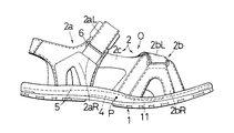
次に、本発明の実施例について説明する。図1、図2及び図3は、本発明の実施例1を示しそれぞれに平面図、1部断面の正面図及び1部断面の背面図である。本発明の実施例1のクリートを取り付けることができるサンダル0は、靴底1と靴底1に固着され足を靴底1に固定するための足固定用帯又はストラップ2とからなる。靴底1は、裏面側にクリート3(図3にのみ表す)をはめ込みとりつけるためのクリート取付孔11を有している。クリート取付孔11は、靴底の中央前方にあり靴底面よりも凹んでいる。
【0018】
クリート3は靴底1の接地面から下方に出ていない。このため、歩行時に足裏に違和感がない。即ち、クリート3の下端面は靴底1の接地面から下方に出ていない。靴底1は、比較的に弾性に乏しい硬質樹脂材料の芯底4と芯底4の上面及び下面に接合され芯底4を弾性的に被覆し比較的に弾性に富む軟質材料の被覆底5とを備えている。心底4は、硬質樹脂、金属などにより成形されている。被覆底5は、硬質のゴム材等により成形されている。
【0019】
足支持用帯2は、足の踵部を固定するための後方側ストラップである踵側足固定用帯2aと足の指先部を固定するための前方側ストラップである指先部側足固定用帯2bとからなる。更に足支持用帯2は、踵側足固定用帯2aと指先部側足固定用帯2bとを足の前後方向に連結する連結帯2cからなる。
【0020】
踵側足固定用帯2aは左側に一端が靴底1に固着され他端が解放可能な左側踵部側固定帯2aLと右側に一端が靴底1に固着され他端が解放可能な右側踵部側固定帯2aRとからなる。指先部側固定帯2bは左側に一端が靴底1に固着され他端が解放可能な左側指先部側固定帯2bLと右側に一端が靴底1に固着され他端が解放可能な右側指先部側固定帯2bRとからなる。
【0021】
連結帯2cは、当該サンダルが左足用であれば左側踵部側固定帯2aLと左側指先部側固定帯2bLとを前後方向に連結している。踵部側固定帯2aは、左側踵部側固定帯2aLの解放側と右側踵部側固定帯2aRの解放側とを結合するための踵側結合手段6を備える。例えば、踵側結合手段6は長穴を備えるリングであり、右側踵部側固定帯2aRの解放端部に縫製などの手段により固着されている。
【0022】
指先部側固定帯2bは、左側指先部側固定帯2bLの解放側と右側指先部側固定帯2bRの解放側とを結合するための指先側結合手段7を備える。例えば、指先側結合手段7は、長穴を備えるリングであり、右側指先部側固定帯2bRの解放端部に縫製などの手段8により固着されている。右側指先部側固定帯2bRの解放端部は折り返され円筒状の縫製部9を縫製により形成することができる。この縫製部9に指先側結合手段7であるリングが通されている。
【0023】
左側踵部側固定帯2aLは、左足用靴の靴底1の左側から立ち上がり、踵側結合手段6を通って折り返している。左側踵部側固定帯2aLの解放側部分の内折り返された部分の向かい合う側にはマジックファスナ(又はベルクロファスナ・登録商標)が固着されている。左側指先部側固定帯2bLは、左足用靴の靴底1の左側から立ち上がり、指先側結合手段7を通って折り返している。左側指先部側固定帯2bLの解放側部分の内折り返された部分の向かい合う側にはマジックファスナ(又はベルクロファスナ・登録商標)が固着されている。
【0024】
以上の説明は左足用のサンダルについてのものであるが、右足用のサンダルは、左足用のサンダルと鏡面対称である。
【0025】
図2,3に示すように、芯底4は踵側の1部を除けば下方に凸状に僅かに湾曲している。芯底4は全体に湾曲しており、変曲点Pを有している。この湾曲は足の指先側部分の下方面に沿うような曲面である。この凸曲面の下端点付近の位置に、クリートをはめ込み取り付けるためのクリート取付孔11が開けられている。底面図である図3に示すように、被覆底5の下側部に窓12が開けられ芯底4の下端面が露出している。
【0026】
芯底4の露出部分4aにクリート取付孔11が開けられている。露出部分4aに下端面から上端面が圧着するクリート3が移動・回転自在に固定されている。クリート3は、複数の6角ボルト13と図に表れていないナットにより芯底4に固定されている。クリート3は、靴底1に対して前後方向に移動させて取り付けることができ、多少であるが前後方向に対する角度を変更することができる。クリート3は、靴底1の下端面から下方には出ていない。
【0027】
図4に示すように、クリート取付孔11は、靴の前後方向に延びる長孔に形成されている。クリート取付孔11は、2つの長孔からなり列状に形成され2列である。2列のクリート取付孔11は、長孔に限られず丸孔、円形孔、楕円形孔が島状に前後方向に並ぶ列孔でよい。2本のクリート取付ボルト13のクリート取付孔11を通る部分は、クリート取付孔11の横幅(前後方向に直交する方向を横方向という)よりそれぞれに小さい。2列の列孔のピッチ即ち2列の列孔の横方向の中心間距離は、14mmに小さく設定されている。靴底の前端から孔列前後方向の中心点までの距離を靴底の前端から後端に至る距離の25乃至45パーセントに設定し、且つ、孔列どうしの前記距離をその孔列近傍における靴底靴幅の25パーセント以下に設定されている。
【0028】
このため、クリート取付孔11の面積は小さいので靴底の強度を損なわない。また、クリート3を傾けて靴底に固定する場合、前記ピッチが小さいのでクリート取付ボルト13とクリート取付孔11との間の隙間が小さくても、クリート3とクリート取付孔11との間の角度は、比較的に大きくすることができる。このような大きい取付角度による固定位置調整は、自転車の乗り手にとって好都合である。
【0029】
図4,5,6,7,8,9,10は、芯底4の構造を詳細に示している。図5は、図4のV−V線断面図である。図6,7,8,9,10は、図11のVI−VI線、VII−VII線、VIII−VIII線、IX−IX線、X−X線における側面断面図である。図5に示すように、芯底4は変曲点P(又は変曲点Pを含む水平線)の近傍領域で厚さが最大である。芯底4は、図6,7に示すように、前方部(変曲点Pよりも指先側の部分)で幅が最大になる。
【0030】
芯底4は、図9,10に示すように、後方部(変曲点Pよりも踵側の部分)で幅が最小になる。心底4は全体的に凹状である。即ち、図6〜10に示すように、左右側が上向きである。幅が最大になる位置にクリート結合用のクリート取付孔11が開けられている。心底4は、中心領域の裏側で前後方向に延びる帯状領域21は、その左右側よりも厚さが厚く形成されている。変曲点Pの前後方向の近傍領域では、心底4は内側(図11で下側)が外側より薄く形成されている。
【0031】
左側指先部側固定帯2bLの解放部の自由端を指先側結合手段7に通して折り曲げる。折り曲げられた左側指先部側固定帯2bLの対向面側のファスナを合わせることにより、左側指先部側固定帯2bLと右側指先部側固定帯2bRとを合着させて緊張させることができる。折曲位置を変えることにより、緊張度を調整することができる。
【0032】
左側踵部側固定帯2aLの解放部の自由端を踵側結合手段6に通して折り曲げる。折り曲げられた左側踵部側固定帯2aLの対向面側のファスナを合わせることにより、左側踵部側固定帯2aLと右側踵部側固定帯2aRとを合着させて緊張させることができる。折曲位置を変えることにより、緊張度を調整することができる。
【0033】
このように緊張度を調整して足の指先部及び踵部を踵側足固定用帯2a及び指先部側固定帯2bにより靴底1に密着させ固定する。このような密着固定状態のサンダルを履いて自転車に乗り、クリート3を自転車のペダルの所定位置にはめ込む。漕ぎ力により靴底1は、変曲点を中心にさらに湾曲しようとするが、周期的に強弱が変動する漕ぎ力が弱くなると同時に芯底4は硬質であるため剛性があり瞬発的に元の形に復元する。
【0034】
このような湾曲力が作用し芯底4が湾曲しかけ連結部2cが伸びようとするが、伸びにくい材質で作られている連結部2cの張力により芯底4の変形が押さえられる。自転車から降りて歩行する場合に、靴底1の下端面から下方には出ていないクリートは歩行の邪魔にならない。空気流れがよいサンダルであるため、スポーツ用靴特に夏季に用いるスポーツ用靴としてふさわしい。
【0035】
図6〜10に示す構造によると、中央部が左右側部よりも厚いので、全体に構造部材として強靭であり、弾力性も失わない。曲がりの中心部で厚いので、曲げにも強い。
【0036】
【発明の効果】
この発明のクリートつきサンダルは、剛性が高く復元性が良いので、エネルギーロスが少ない。自転車用靴として歩行用靴として両用できる。緊張度の調整が容易である。クリート取付角度範囲が広い。
【図面の簡単な説明】
【図1】図1は、本発明のクリート孔つきサンダルの実施例1を示す正面図である。
【図2】図2は、図1の平面図である。
【図3】図3は、図2の底面図である。
【図4】図4は、本発明のクリートつきサンダルの芯底4の実施例1を示す平面図である。
【図5】図5は、図4のV−V線断面図である。
【図6】図6は、図11のVI−VIである。
【図7】図7は、図11のVII−VII線断面図である。
【図8】図8は、図4のVIII−VIII線断面図である。
【図9】図9は、図4のIX−IX線断面図である。
【図10】図10は、図4のX−X線断面図である。
【図11】図11は、図5の背面図である。
【符号の説明】
1…靴底
2…足固定用帯
3…クリート
4…芯底
5…被覆底
2a…踵側足固定用帯
2b…指先部側足固定用帯
2aL…左側踵部側固定帯
2aR…右側踵部側固定帯
2bL…左側指先部側固定帯
2bR…右側指先部側固定帯
21…帯状領域[0001]
[Industrial applications]
The present invention relates to sandals to which cleats can be attached. More specifically, the present invention relates to a sandal that can be used as a bicycle sandal if a cleat suitable for walking is attached.
[0002]
[Prior art]
Bicycles are becoming increasingly lighter. The load is reduced by the weight reduction and the improvement of the transmission function, and the sport of the bicycle is promoted. The load is reduced, and bicycle shoes are being improved more and more rapidly. Reducing leg energy loss is an important factor for sports cars. Bicycle shoes with cleats have been known to reduce the loss of leg energy (for example, JP-A-3-254702). In such bicycle shoes, the rigidity of the shoe itself and the integrity of the shoe and the foot are required. The rigidity of the shoe is ensured by a hard sole, and the integrity of the shoe and the foot is ensured by tightening the periphery of the shoe to the foot.
[0003]
[Problems to be solved by the invention]
The sportization of bicycles demands convenience at the destination by bicycle. For example, walking properties of bicycle shoes are required when going away. If conventional bicycle shoes are used for walking on the go in the summer, the feet become stuffy.
[0004]
The present invention has been made based on such a technical background, and achieves the following objects.
[0005]
An object of the present invention is to provide a sandal which can be formed into a sandal and to which a cleat can be attached.
[0006]
Another object of the present invention is to provide a sandal which can be formed into a sandal and a cleat can be attached while securing rigidity.
[0007]
Still another object of the present invention is to provide a sandal that can be formed into sandals and cleats can be attached while securing rigidity and integrity.
[0008]
[Means for Solving the Problems]
The following means are adopted to solve the above-mentioned problems.
[0012]
[Means for Solving the Problems]
The sandal of the
The sole has a cleat mounting hole for attaching a cleat,
The portion near the cleat mounting hole,
The cleat mounting hole is in a row in front of the center of the sole and is recessed from the sole of the sole,
The row of cleat mounting holes is two rows,
The distance from the front end of the sole to the center point in the front-back direction of the hole array is set to 25 to 45% of the distance from the front end to the rear end of the sole, and the distance between the hole arrays is set to the hole array. Set to less than 25% of the width of the shoe sole in the vicinity,
The strap includes a front strap for fixing a toe portion of a foot and a rear strap for fixing a heel portion of a foot, and the front strap and the rear strap are connected by a connection band,
The front strap has a fingertip-side fixed band (2b) with one end fixed to the outside at the shoe sole (1), and the other end releasable with an outer fingertip-side fixed band (2bL) and one inside at the sole. (1b) an inner fingertip fixed band (2bR) fixed to the other end and releasable at the other end,
In the rear strap, one end of the heel-side fixing band (2a) is fixed to the shoe sole (1) on the outside, and the other end is releasable from the outer heel-side fixing band (2aL) and the inner end of the shoe is fixed to the shoe. An inner heel-side fixed band (2aR) fixed to the bottom (1) and the other end of which is releasable; and a heel formed by connecting the outer heel-side fixed band (2aL) and the inner heel-side fixed band (2aR). Consists of a band that fixes the upper part of
The connection band (2c) is characterized in that the outer heel-side fixed band (2aL) and the outer fingertip-side fixed band (2bL) are connected only at the upper part in the front-rear direction .
[0013]
A sandal according to a second aspect of the present invention is the sandal according to the first aspect of the present invention, wherein the pitch of the row of holes is preferably 14 mm or less.
[0016]
[Action]
The sandals of the present invention can be used as walking sandals. In this case, cleats may be attached. The sandals of the present invention can be used as bicycle sandals by attaching cleats. The angle of the cleat that fits in the two rows of slots is adjusted.
[0017]
【Example】
Next, examples of the present invention will be described. 1, 2 and 3 show a first embodiment of the present invention, and are respectively a plan view, a front view of a partial cross section, and a rear view of a partial cross section. The sandal 0 to which the cleat according to the first embodiment of the present invention can be attached includes a
[0018]
The cleat 3 does not protrude downward from the contact surface of the sole 1. For this reason, there is no sense of incongruity in the sole when walking. That is, the lower end surface of the cleat 3 does not protrude downward from the contact surface of the
[0019]
The
[0020]
The heel-side foot-fixing
[0021]
If the sandal is for the left foot, the connecting band 2c connects the left heel side fixed band 2aL and the left fingertip side fixed band 2bL in the front-rear direction. The heel-
[0022]
The fingertip-side fixed
[0023]
The left heel side fixed band 2aL rises from the left side of the sole 1 of the left foot shoe, and is folded back through the heel side coupling means 6. A magic fastener (or Velcro fastener (registered trademark)) is fixed to the left heel side fixing band 2aL on the opposite side of the inwardly folded portion of the release side portion. The left fingertip side fixed band 2bL rises from the left side of the sole 1 of the left foot shoe, and is folded back through the fingertip coupling means 7. A magic fastener (or Velcro fastener (registered trademark)) is fixed to a side of the left folded portion of the left fingertip-side fixed band 2bL opposite to the inside folded portion.
[0024]
Although the above description is about the sandals for the left foot, the sandals for the right foot are mirror-symmetric with the sandals for the left foot.
[0025]
As shown in FIGS. 2 and 3, the core sole 4 is slightly curved convexly downward except for a part on the heel side. The core bottom 4 is entirely curved and has an inflection point P. This curvature is a curved surface along the lower surface of the toe side portion of the foot. At a position near the lower end point of the convex curved surface, a
[0026]
A
[0027]
As shown in FIG. 4, the
[0028]
For this reason, since the area of the
[0029]
4, 5, 6, 7, 8, 9, and 10 show the structure of the core bottom 4 in detail. FIG. 5 is a sectional view taken along line VV of FIG. 6, 7, 8, 9, and 10 are side cross-sectional views taken along lines VI-VI, VII-VII, VIII-VIII, IX-IX, and XX in FIG. As shown in FIG. 5, the core bottom 4 has the maximum thickness in the vicinity of the inflection point P (or a horizontal line including the inflection point P). As shown in FIGS. 6 and 7, the core bottom 4 has the maximum width at the front part (the part closer to the fingertip than the inflection point P).
[0030]
As shown in FIGS. 9 and 10, the width of the core bottom 4 is minimum at a rear portion (a portion closer to the heel than the inflection point P). The base 4 is generally concave. That is, as shown in FIGS. 6 to 10, the left and right sides are upward. A
[0031]
The free end of the release portion of the left fingertip-side fixed band 2bL is bent through the fingertip-side coupling means 7. By aligning the fasteners on the opposing surface of the bent left fingertip-side fixed band 2bL, the left fingertip-side fixed band 2bL and the right fingertip-side fixed band 2bR can be attached and tightened. By changing the bending position, the degree of tension can be adjusted.
[0032]
The free end of the release portion of the left heel side fixing band 2aL is bent through the heel side coupling means 6. By aligning the fasteners on the opposite surface side of the bent left heel part-side fixing band 2aL, the left heel part-side fixing band 2aL and the right heel part-side fixing band 2aR can be attached and tightened. By changing the bending position, the degree of tension can be adjusted.
[0033]
By adjusting the degree of tension in this manner, the toe portion and the heel portion of the foot are brought into close contact with the
[0034]
Such a bending force acts to cause the core bottom 4 to bend and the connecting portion 2c to expand, but the deformation of the core bottom 4 is suppressed by the tension of the connecting portion 2c made of a material that is difficult to expand. When walking off the bicycle, cleats that do not protrude from the lower end surface of the sole 1 do not hinder walking. Since the sandals have a good air flow, they are suitable for sports shoes, especially sports shoes used in summer.
[0035]
According to the structure shown in FIGS. 6 to 10, the central portion is thicker than the left and right side portions, so that the structure is strong as a whole and does not lose elasticity. Since it is thick at the center of the bend, it is also strong against bending.
[0036]
【The invention's effect】
ADVANTAGE OF THE INVENTION Since the sandals with cleats of this invention have high rigidity and good restorability, energy loss is small. It can be used both as bicycle shoes and walking shoes. Adjustment of tension is easy. Wide cleat mounting angle range.
[Brief description of the drawings]
FIG. 1 is a front view showing a sandal with cleat holes according to a first embodiment of the present invention.
FIG. 2 is a plan view of FIG. 1;
FIG. 3 is a bottom view of FIG. 2;
FIG. 4 is a plan
FIG. 5 is a sectional view taken along line VV of FIG. 4;
FIG. 6 is VI-VI of FIG. 11;
FIG. 7 is a sectional view taken along line VII-VII of FIG. 11;
FIG. 8 is a sectional view taken along line VIII-VIII in FIG. 4;
FIG. 9 is a sectional view taken along line IX-IX of FIG. 4;
FIG. 10 is a sectional view taken along line XX of FIG. 4;
FIG. 11 is a rear view of FIG. 5;
[Explanation of symbols]
DESCRIPTION OF
Claims (2)
前記靴底はクリートを取りつけるためのクリート取付孔を有し、
前記クリート取付孔の近傍部分は、
前記靴底の中央前方にあり前記靴底の靴底面より凹んであり、前記クリート取付孔は列状であり、
前記クリート取付孔の孔列は2列であり、
前記靴底の前端から前記孔列前後方向の中心点までの距離を前記靴底の前端から後端に至る距離の25乃至45パーセントに設定し、且つ、前記孔列どうしの距離を前記孔列近傍における前記靴底靴幅の25パーセント以下に設定してあり、
前記ストラップは、足の指先部を固定するための前方側ストラップと足の踵部を固定するための後方側ストラップとからなり、前記前方側ストラップと前記後方側ストラップとは連結帯により連結され、
前記前方側ストラップは、指先部側固定帯(2b)は外側に一端が靴底(1)に固着され、他端が解放可能な外側指先部側固定帯(2bL)と内側に一端が靴底(1)に固着され他端が解放可能な内側指先部固定帯(2bR)とからなり、
前記後方側ストラップは、踵側足固定用帯(2a)は外側に一端が靴底(1)に固着され、他端が解放可能な外側踵部側固定帯(2aL)と内側に一端が靴底(1)に固着され他端が解放可能な内側踵部側固定帯(2aR)、及び前記外側踵部側固定帯(2aL)と前記内側踵部側固定帯(2aR)とを連結し踵の上部を固定する帯とからなり、
前記連結帯(2c)は、前記外側踵部側固定帯(2aL)と前記外側指先部側固定帯(2bL)とを前後方向に上部のみで連結している
ことを特徴とするサンダル。Sandals consisting of soles and straps,
The sole has a cleat mounting hole for attaching a cleat,
The portion near the cleat mounting hole,
The cleat mounting hole is in a row in front of the center of the sole and is recessed from the sole of the sole,
The row of cleat mounting holes is two rows,
The distance from the front end of the sole to the center point in the front-back direction of the hole array is set to 25 to 45% of the distance from the front end to the rear end of the sole, and the distance between the hole arrays is set to the hole array. Set to less than 25% of the width of the shoe sole in the vicinity,
The strap includes a front strap for fixing a toe portion of a foot and a rear strap for fixing a heel portion of a foot, and the front strap and the rear strap are connected by a connection band,
The front strap has a fingertip-side fixed band (2b) with one end fixed to the outside at the shoe sole (1), and the other end releasable with an outer fingertip-side fixed band (2bL) and one inside at the sole. (1b) an inner fingertip fixed band (2bR) fixed to the other end and releasable at the other end,
In the rear strap, one end of the heel-side fixing band (2a) is fixed to the shoe sole (1) on the outside, and the other end is releasable from the outer heel-side fixing band (2aL) and the inner end of the shoe is fixed to the shoe. An inner heel-side fixed band (2aR) fixed to the bottom (1) and the other end of which is releasable; and a heel formed by connecting the outer heel-side fixed band (2aL) and the inner heel-side fixed band (2aR). Consists of a band that fixes the upper part of
The connecting band (2c) connects the outer heel-side fixed band (2aL) and the outer fingertip-side fixed band (2bL) only at the upper part in the front-rear direction. Sandals.
前記孔列のピッチは14mm以下である
ことを特徴とするサンダル。The sandals according to claim 1,
Sandals characterized in that the pitch of the row of holes is 14 mm or less.
Priority Applications (5)
| Application Number | Priority Date | Filing Date | Title |
|---|---|---|---|
| JP18106095A JP3590141B2 (en) | 1995-06-23 | 1995-06-23 | Sandals |
| US08/665,420 US5687492A (en) | 1995-06-23 | 1996-06-18 | Sandal |
| EP96304607A EP0749704B1 (en) | 1995-06-23 | 1996-06-21 | Sandal |
| DE69610030T DE69610030T2 (en) | 1995-06-23 | 1996-06-21 | sandal |
| CN96106895.7A CN1089569C (en) | 1995-06-23 | 1996-06-24 | Sandals |
Applications Claiming Priority (1)
| Application Number | Priority Date | Filing Date | Title |
|---|---|---|---|
| JP18106095A JP3590141B2 (en) | 1995-06-23 | 1995-06-23 | Sandals |
Publications (2)
| Publication Number | Publication Date |
|---|---|
| JPH0910003A JPH0910003A (en) | 1997-01-14 |
| JP3590141B2 true JP3590141B2 (en) | 2004-11-17 |
Family
ID=16094089
Family Applications (1)
| Application Number | Title | Priority Date | Filing Date |
|---|---|---|---|
| JP18106095A Expired - Fee Related JP3590141B2 (en) | 1995-06-23 | 1995-06-23 | Sandals |
Country Status (5)
| Country | Link |
|---|---|
| US (1) | US5687492A (en) |
| EP (1) | EP0749704B1 (en) |
| JP (1) | JP3590141B2 (en) |
| CN (1) | CN1089569C (en) |
| DE (1) | DE69610030T2 (en) |
Families Citing this family (33)
| Publication number | Priority date | Publication date | Assignee | Title |
|---|---|---|---|---|
| JP3199357B2 (en) * | 1996-03-15 | 2001-08-20 | 株式会社シマノ | Sole core body of cycling shoe, method of molding the same, and mold device therefor |
| FR2775424B1 (en) | 1998-03-02 | 2000-03-31 | Salomon Sa | CYCLING SHOE HAVING AN AUTOMATIC LOCKING SHOE ON A PEDAL |
| US6052920A (en) * | 1998-04-10 | 2000-04-25 | Bite, Llc | Sandal with x-cross weave straps |
| USD417947S (en) * | 1998-05-28 | 1999-12-28 | Wolverine World Wide, Inc. | Sandal upper |
| USD422402S (en) * | 1998-05-28 | 2000-04-11 | Wolverine World Wide, Inc. | Sandal upper |
| USD421330S (en) * | 1998-05-29 | 2000-03-07 | Wolverine World Wide, Inc. | Sandal upper |
| US6237249B1 (en) * | 1999-04-22 | 2001-05-29 | South Cone, Inc. | Convertible slide and method |
| US6189242B1 (en) * | 1999-11-29 | 2001-02-20 | Mikel Lin | Shoe for bicycle |
| US7584553B1 (en) | 2006-04-07 | 2009-09-08 | Medley Mark M | Flip flop golf sandal |
| US20100223809A1 (en) * | 2009-03-05 | 2010-09-09 | David Neil Hensch | Sandal with Cleats |
| US8141274B2 (en) * | 2009-05-26 | 2012-03-27 | Shimano Inc. | Rowing shoe |
| USD759255S1 (en) | 2010-05-17 | 2016-06-14 | Anne C. Bradley | Orthopedic shoe |
| JP5981425B2 (en) * | 2010-06-17 | 2016-08-31 | ダッシュアメリカ インコーポレイテッドDashamerica,Inc. | Midsole for footwear |
| US20130312290A1 (en) * | 2010-10-15 | 2013-11-28 | Rohan Donald | Cycling pedal device |
| WO2012135007A2 (en) | 2011-03-25 | 2012-10-04 | Dashamerica, Inc. D/B/A Pearl Izumi Usa, Inc. | Flexible shoe sole |
| CA2822871C (en) * | 2011-12-13 | 2014-04-22 | Equipower Sports Ltd. (0930496 Bc Ltd) | Footwear for use in specialized activities |
| CN102600595A (en) * | 2012-03-23 | 2012-07-25 | 温州大学 | Board-shoe racing device |
| FR3024822B1 (en) * | 2014-08-13 | 2016-08-26 | Mavic Sas | SPORTS SHOE |
| US9596906B2 (en) * | 2015-04-23 | 2017-03-21 | Action Sports Equipment, Inc. | Article of footwear with concave portion |
| US20180055150A1 (en) * | 2016-08-29 | 2018-03-01 | Philip Shrader | Removable shoe adaptors |
| USD855950S1 (en) * | 2017-10-12 | 2019-08-13 | Birkenstock Sales GmbH | Sandal |
| USD985894S1 (en) | 2020-08-07 | 2023-05-16 | Target Brands, Inc. | Footwear |
| USD986543S1 (en) | 2020-08-07 | 2023-05-23 | Target Brands, Inc. | Footwear |
| USD985895S1 (en) | 2020-08-07 | 2023-05-16 | Target Brands, Inc. | Footwear |
| USD955091S1 (en) | 2020-08-14 | 2022-06-21 | Target Brands, Inc. | Footwear |
| USD957105S1 (en) | 2020-08-14 | 2022-07-12 | Target Brands, Inc. | Footwear |
| USD943913S1 (en) | 2020-08-14 | 2022-02-22 | Target Brands, Inc. | Footwear upper |
| USD950913S1 (en) | 2020-08-25 | 2022-05-10 | Target Brands, Inc. | Footwear |
| USD950904S1 (en) | 2020-08-25 | 2022-05-10 | Target Brands, Inc. | Footwear |
| US20220175081A1 (en) * | 2020-12-04 | 2022-06-09 | Lisa L. Sutherland | Breathable stationary bicycle shoe |
| DE202021102913U1 (en) * | 2021-05-28 | 2022-09-05 | Jannik Reker | Adapter device for a click element |
| USD1000054S1 (en) * | 2022-04-22 | 2023-10-03 | Shenzhen Yuexing Relu Technology Co., Ltd. | Shoe |
| USD1021350S1 (en) * | 2023-07-17 | 2024-04-09 | Converse Inc. | Shoe |
Family Cites Families (17)
| Publication number | Priority date | Publication date | Assignee | Title |
|---|---|---|---|---|
| US2894338A (en) * | 1956-12-10 | 1959-07-14 | William M Scholl | Stabilizing and foot supporting sandal |
| US2807098A (en) * | 1957-06-10 | 1957-09-24 | Gordon C Wunker | Foot protector |
| US2932911A (en) * | 1958-03-14 | 1960-04-19 | Musebeck Shoe Company | Sandals with flexible arch support |
| US3323233A (en) * | 1964-07-06 | 1967-06-06 | William M Scholl | Article of footwear and method of making the same |
| DE2240102A1 (en) * | 1972-08-16 | 1974-02-28 | Limberger Heinz | CYCLING SHOES WITH A SOLE MADE OF THERMOPLASTIC PLASTICS |
| FR2350803A1 (en) * | 1976-05-13 | 1977-12-09 | Detto Pietro Di Luigi Raini | Cyclist shoe with plastic e.g. nylon sole - has elongated inverted T=section grooves for adjustable bolted connection pedal-key plate |
| FR2464660A1 (en) * | 1979-09-10 | 1981-03-20 | Camuset | LEATHER PEDAL DEVICE FOR CYCLING SHOE |
| ATE67644T1 (en) * | 1987-07-06 | 1991-10-15 | Look Sa | CYCLING SHOE. |
| FR2620002B1 (en) * | 1987-09-08 | 1990-09-21 | Jean Pierre Creations | ADJUSTABLE SHOE SOLE |
| US4793075A (en) * | 1987-09-15 | 1988-12-27 | Mark Thatcher | Sport sandal for active wear |
| DE3825089A1 (en) * | 1988-07-23 | 1990-01-25 | Jacoform International Handels | Sandal |
| FR2653089B1 (en) * | 1989-10-16 | 1994-04-08 | Jean Beyl | DEVICE FOR FIXING A SHOE ON A BICYCLE OR THE LIKE PEDAL, BICYCLE PEDAL, SHOE AND SHOE SOLE FOR SUCH A DEVICE. |
| JPH0496202U (en) * | 1991-01-25 | 1992-08-20 | ||
| US5561919A (en) * | 1992-08-27 | 1996-10-08 | Gill; Yoram | Sandal having independenty adjustable straps |
| US5438767A (en) * | 1993-12-16 | 1995-08-08 | E. S. Originals, Inc. | Sandal having adjustable straps |
| US5465506A (en) * | 1994-01-19 | 1995-11-14 | Karhu Usa Inc. | Sandal fastening system |
| US5473963A (en) * | 1994-11-17 | 1995-12-12 | Aeschbach; James F. | Magnetic bicycle pedal foot retainer |
-
1995
- 1995-06-23 JP JP18106095A patent/JP3590141B2/en not_active Expired - Fee Related
-
1996
- 1996-06-18 US US08/665,420 patent/US5687492A/en not_active Expired - Fee Related
- 1996-06-21 EP EP96304607A patent/EP0749704B1/en not_active Expired - Lifetime
- 1996-06-21 DE DE69610030T patent/DE69610030T2/en not_active Expired - Fee Related
- 1996-06-24 CN CN96106895.7A patent/CN1089569C/en not_active Expired - Fee Related
Also Published As
| Publication number | Publication date |
|---|---|
| JPH0910003A (en) | 1997-01-14 |
| CN1140038A (en) | 1997-01-15 |
| EP0749704A3 (en) | 1997-03-05 |
| US5687492A (en) | 1997-11-18 |
| EP0749704A2 (en) | 1996-12-27 |
| CN1089569C (en) | 2002-08-28 |
| DE69610030D1 (en) | 2000-10-05 |
| DE69610030T2 (en) | 2001-05-03 |
| EP0749704B1 (en) | 2000-08-30 |
Similar Documents
| Publication | Publication Date | Title |
|---|---|---|
| JP3590141B2 (en) | Sandals | |
| US6293566B1 (en) | Unitary strap for use in a soft boot snowboard binding | |
| US6502330B1 (en) | Sole for footwear | |
| USRE35452E (en) | Single point triangular adjustment system for sandals | |
| US20070063459A1 (en) | Interface system for retaining a foot or a boot on a sports article | |
| US6606803B1 (en) | Footwear sole and arch strapping system | |
| US5363573A (en) | Rotatable cleat | |
| US6729047B2 (en) | Strap assembly for sport shoe | |
| US7930841B2 (en) | Article of footwear for water sports | |
| EP0884004B1 (en) | Article of footwear | |
| US6052920A (en) | Sandal with x-cross weave straps | |
| US20050044748A1 (en) | Tongue reinforcement for a boot, a reinforced tongue and a boot provided with such tongue | |
| US20040020081A1 (en) | Sport boot | |
| US6971190B2 (en) | Foot retention device | |
| JPH09122289A (en) | Binding device to tighten and fix shoes to sporting instrument | |
| US6368173B1 (en) | Foot retention device | |
| US7320475B2 (en) | Device for retaining a foot or a boot on a sports apparatus | |
| EP0948910A2 (en) | A snowboard boot having an asymmetrical support member | |
| EP1109467B1 (en) | Footwear with arch strapping system | |
| AU2001285138A1 (en) | Foot retention device | |
| JP3754702B2 (en) | Unique underwater flippers | |
| US20190133256A1 (en) | Skate boot with resilient upper strap | |
| JP3014091B2 (en) | Back support system for snowboard boots | |
| JPH0633842Y2 (en) | Shoe sole | |
| JPS6031522Y2 (en) | ski shoes |
Legal Events
| Date | Code | Title | Description |
|---|---|---|---|
| A521 | Written amendment |
Free format text: JAPANESE INTERMEDIATE CODE: A523 Effective date: 20040705 |
|
| A61 | First payment of annual fees (during grant procedure) |
Free format text: JAPANESE INTERMEDIATE CODE: A61 Effective date: 20040819 |
|
| R150 | Certificate of patent or registration of utility model |
Free format text: JAPANESE INTERMEDIATE CODE: R150 |
|
| LAPS | Cancellation because of no payment of annual fees |