EP2687445A1 - Measurement of the inertial properties of an aircraft movable control surface - Google Patents
Measurement of the inertial properties of an aircraft movable control surface Download PDFInfo
- Publication number
- EP2687445A1 EP2687445A1 EP12382293.4A EP12382293A EP2687445A1 EP 2687445 A1 EP2687445 A1 EP 2687445A1 EP 12382293 A EP12382293 A EP 12382293A EP 2687445 A1 EP2687445 A1 EP 2687445A1
- Authority
- EP
- European Patent Office
- Prior art keywords
- movable
- momentum
- mechanical arrangement
- control surface
- hinge line
- Prior art date
- Legal status (The legal status is an assumption and is not a legal conclusion. Google has not performed a legal analysis and makes no representation as to the accuracy of the status listed.)
- Granted
Links
- 238000005259 measurement Methods 0.000 title description 4
- 238000000034 method Methods 0.000 claims abstract description 42
- 230000003068 static effect Effects 0.000 claims abstract description 26
- 230000010355 oscillation Effects 0.000 claims abstract description 11
- 238000007670 refining Methods 0.000 claims abstract description 7
- 238000013459 approach Methods 0.000 claims abstract description 6
- 230000001939 inductive effect Effects 0.000 claims abstract 2
- 239000003381 stabilizer Substances 0.000 claims description 4
- 230000005484 gravity Effects 0.000 description 7
- 230000005284 excitation Effects 0.000 description 4
- 230000003213 activating effect Effects 0.000 description 2
- 238000004458 analytical method Methods 0.000 description 2
- YTAHJIFKAKIKAV-XNMGPUDCSA-N [(1R)-3-morpholin-4-yl-1-phenylpropyl] N-[(3S)-2-oxo-5-phenyl-1,3-dihydro-1,4-benzodiazepin-3-yl]carbamate Chemical compound O=C1[C@H](N=C(C2=C(N1)C=CC=C2)C1=CC=CC=C1)NC(O[C@H](CCN1CCOCC1)C1=CC=CC=C1)=O YTAHJIFKAKIKAV-XNMGPUDCSA-N 0.000 description 1
- 238000010009 beating Methods 0.000 description 1
- 230000037406 food intake Effects 0.000 description 1
- XLYOFNOQVPJJNP-UHFFFAOYSA-N water Substances O XLYOFNOQVPJJNP-UHFFFAOYSA-N 0.000 description 1
Images


Classifications
-
- B—PERFORMING OPERATIONS; TRANSPORTING
- B64—AIRCRAFT; AVIATION; COSMONAUTICS
- B64F—GROUND OR AIRCRAFT-CARRIER-DECK INSTALLATIONS SPECIALLY ADAPTED FOR USE IN CONNECTION WITH AIRCRAFT; DESIGNING, MANUFACTURING, ASSEMBLING, CLEANING, MAINTAINING OR REPAIRING AIRCRAFT, NOT OTHERWISE PROVIDED FOR; HANDLING, TRANSPORTING, TESTING OR INSPECTING AIRCRAFT COMPONENTS, NOT OTHERWISE PROVIDED FOR
- B64F5/00—Designing, manufacturing, assembling, cleaning, maintaining or repairing aircraft, not otherwise provided for; Handling, transporting, testing or inspecting aircraft components, not otherwise provided for
- B64F5/60—Testing or inspecting aircraft components or systems
-
- G—PHYSICS
- G01—MEASURING; TESTING
- G01M—TESTING STATIC OR DYNAMIC BALANCE OF MACHINES OR STRUCTURES; TESTING OF STRUCTURES OR APPARATUS, NOT OTHERWISE PROVIDED FOR
- G01M1/00—Testing static or dynamic balance of machines or structures
- G01M1/10—Determining the moment of inertia
-
- G—PHYSICS
- G01—MEASURING; TESTING
- G01M—TESTING STATIC OR DYNAMIC BALANCE OF MACHINES OR STRUCTURES; TESTING OF STRUCTURES OR APPARATUS, NOT OTHERWISE PROVIDED FOR
- G01M7/00—Vibration-testing of structures; Shock-testing of structures
- G01M7/02—Vibration-testing by means of a shake table
Definitions
- the present invention relates to a method for measuring the inertial properties (static momentum, frictional momentum and momentum of inertia) of an aircraft movable control surface.
- the invention further refers to a mechanical arrangement for operating the cited method.
- Aircraft movable control surfaces such as aircraft elevators, have to be sometimes, under certain circumstances, tested in order to determine whether or not they comply with certain acceptance criteria.
- the practical method used for determining the acceptance of a movable control surface is the measurement of its mass and of its centre of gravity, these two components allowing the calculation of its static momentum, such that this static momentum remains within a certain range.
- Aircraft movable control surfaces vary slightly their mass, after some period of operation, by water ingestion or by any other matters, or immediately after a damaged unit has been repaired, as these reparations often need extra patches. For this reason, the mass control has to be monitored in time, so that the inertial properties of the movable control surface remain under acceptable limits, as any deviation would affect the dynamic behaviour of the aircraft. Consequently, the control of the inertial properties of the movable control surface is essential.
- the affected unit needs to be removed from the aircraft, which is a cumbersome process requiring long timings and being costly and unpractical, as the process is performed with a crane or other means and needs one hanging scale in each of the hoist points.
- it To get the correct weight of the control surface, it must be unlinked from the aircraft structure such that, when an elevator is measured, for example, the elevator has to be removed from its stabilizer and needs to be lifted with a crane through a sling attached to each of the hoist points, using a hanging scale in each of the hoist points attached to the sling. This task is performed by operators manually, being unpractical, time consuming and highly costly.
- the present invention proposes a different method of acceptance for aircraft movable control surfaces.
- the acceptance of an aircraft movable control surface is made by controlling its inertial properties (static momentum, frictional momentum and momentum of inertia), such that these inertial properties remain within a certain range.
- the method of the invention does not require the removal of the movable control surface from the aircraft.
- the aircraft elements object of the method disclosed in the present invention are, precisely, the movable parts of the aircraft movable control surfaces, hereinafter called movables.
- a first object of the invention is to provide a method for obtaining the inertial properties of a movable.
- Another object of the invention is to provide a mechanical arrangement for operating the above-mentioned method.
- the main advantage of the method in the invention is that the inertial properties of the movable are obtained without its removal from the aircraft, which means that the costs involved in the method are significantly reduced compared to the known procedures on the prior art.
- the mechanical arrangement used in the method of the invention comprises the following elements:
- the method of the invention is directed towards obtaining the inertial properties of the movable, the method comprising the following steps:
- the method of the invention analyses the response to forced oscillations of said movable 10: in the Figures attached, the corresponding case of an elevator has been represented, where this movable 10 (elevator) rotates around a hinge line 2.
- the mechanical arrangement 20 for operating the above-mentioned method is schematically represented in Figures 1b and 2 , and it comprises:
- a possible embodiment of the vibration generator 500 is shown in Figure 6 , comprising an eccentric mass 800, that rotates around an axis 802, at a distance of 801. Different embodiments of the vibration generator 500 are also possible.
- Both parts 100 and 200 are connected mechanically by means of the elastic element 300, typically a spring having a known elastic constant and having an adjustable position by means of an adjusting device 3, as shown in Figure 3 .
- the elastic element 300 is attached on one of its sides to the first part 100, and is attached on the other of its sides to the second part 200, the elastic element 300 being displaceable on one of its sides, therefore allowing the adjustment of the rest position of the mechanical arrangement 20.
- Each control surface 1 item typically an elevator, will have associated a specific elastic element 300, typically a spring, having an elastic constant that is chosen to produce a suitable resonance frequency of the movable assembly 40, typically 2 Hz.
- the adjusting device 3 allows the adjustment of the mechanical arrangement 20 to the angular position of the movable assembly 40, therefore fixing the zero position for carrying out the method of the invention.
- the movable assembly 40 after the elastic element 300 has been connected and once the balance has been performed, constitutes a second order mechanical system. This system has a resonance frequency which is a function of the elastic constant of the elastic element 300 and of the momentum of inertia of the movable assembly 40.
- the elastic constant of the elastic element 300 is a function of a desirable resonance frequency that has been chosen, the real resonance frequency is unknown (to be determined) but will be very close to that used to obtain the elastic constant of the elastic element 300.
- the mechanical arrangement 20 is also connected to a computer (laptop) and some portable electric equipment, in order to analyse the data and carry out the method of the invention.
- a preferred embodiment of the mechanical arrangement 20 would entail that the vibration generator 500 is located on the left side of the mechanical arrangement 20, and would be comprised within the adjustable counterweight 600 structure: the momentum of inertia of the movable assembly 40 is reduced, which improves the quality of the measurement.
- the method proposed in this invention allows to adjust the frequency of the vibration generator 500: this frequency increases progressively (from a lower value than that of the resonance), until the maximum deflection of the movable 10 gets close to the admissible limits known for the control surface 1, which indicates the close proximity to the resonance frequency of the movable assembly 40, as it will be further explained in detail.
- the method of the invention is therefore directed towards the measurement of the inertial properties of the movable 10 of a control surface 1, this movable 10 being typically an elevator, the method comprising the following steps:
- step h) the wave response (position angle versus time) of the movable assembly 40 is acquired at a high rate, for example above 10000 samples/second: from this response, the frequency of the first lobe (W lobe ) is obtained. Also, in step h), the output of the vibration generator 500 is obtained: from this response, the output rotation frequency ( ⁇ rot ) of the vibration generator 500 is obtained.
- a computer is used for acquiring and treating the wave response in h) and for calculating the frequency of the first lobe (W lobe ) and the output rotation frequency ( ⁇ rot ) of the vibration generator 500.
- Figure 7 shows the plotted response obtained in step h), showing the position angle versus time of the movable assembly 40, when the excitation frequency provided by the vibration generator 500 is far from the resonance frequency of the movable assembly 40.
- the type of response is that shown in Figure 8 : this response is suitable for obtaining the momentum of inertia of the movable assembly 40 (I tot ).
- the period of the lobe (W lobe ), can thus be accurately measured, and entered in the formula (1) above.
- the protocol starts with a rotation frequency ( ⁇ rot ) of the vibration generator 500 lower than the expected resonance frequency of the movable assembly 40 (W reson ); the process is then repeated with frequencies of rotation ( ⁇ rot ) that are progressively higher; the different plotted responses are observed, until the maximum lobe amplitude approaches the maximum deflection allowed for the movable 10: at this stage, the rotation frequency ( ⁇ rot ) and the period of the lobe (W lobe ) are appropriate for being entered in the formula (1), where the value of the resonance frequency of the movable assembly 40 (W reson ) is calculated.
- an additional advantage of the method of the invention is the simultaneous calculation of the frictional momentum of the movable 10 when rotating around the hinge line 2, as cited in step e) above.
- the mechanical arrangement 20 of the control surface 1 is used without the elastic element 300.
- the centre of gravity of the movable assembly 40 would be aligned with the hinge line 2 if there existed no frictional momentum; as a small frictional momentum exists, this situation does not occur and the centre of gravity of the movable assembly 40 has a small offset with respect to the hinge line 2.
- the increment of the static momentum ( ⁇ M static) of the movable 10 is calculated using the formula (5) above, as a first approach.
- This value of ⁇ M static is then used for refining the static momentum of the movable 10 (as cited in step e) above): an element having a mass calculated such that it provides a static momentum that neutralizes the static momentum of the movable 10, this element being located at a certain distance from the hinge line 2 (to the right side or the left side of the hinge line 2, depending on the mathematical sign obtained from the formula (5)) is used for carrying out the rest of the method steps f) to l).
- the mathematic signs used are such that the positive sign corresponds to the elevator, rotating in a clockwise sense.
- lobe used in the present invention disclosure When a mechanical system is excited with a frequency close to its natural resonance, its response follows a movement, angular in this case, as the one represented in Figure 8 .
- the term lobe used in this description corresponds to a set of oscillations that starts with the zero level of the origin of one oscillation having minimum amplitude and finishes with the zero level of the end of the next oscillation having minimum amplitude: for example, in Figure 8 , there is only one of these lobes being shown.
Landscapes
- Engineering & Computer Science (AREA)
- Physics & Mathematics (AREA)
- General Physics & Mathematics (AREA)
- Aviation & Aerospace Engineering (AREA)
- Manufacturing & Machinery (AREA)
- Transportation (AREA)
- Vibration Prevention Devices (AREA)
- Cage And Drive Apparatuses For Elevators (AREA)
- Mechanical Engineering (AREA)
- Automation & Control Theory (AREA)
- Measurement Of Mechanical Vibrations Or Ultrasonic Waves (AREA)
Abstract
a) removing the actuators mechanical connections from the movable (10), leaving it free to rotate around its hinge line (2), further balancing the movable (10) and calculating in a first approach its coarse static momentum;
b) refining the static momentum of the movable (10) obtained in a), and obtaining simultaneously its frictional momentum;
c) incorporating an elastic element (300) on the control surface (1), configuring a second order mechanical system;
d) inducing forced oscillations on the movable (10) at a certain frequency, this frequency being increased until it is sensibly close to the resonance frequency of the movable (10);
e) calculating, from the wave response in d), the momentum of inertia of the movable (10).
Description
- The present invention relates to a method for measuring the inertial properties (static momentum, frictional momentum and momentum of inertia) of an aircraft movable control surface. The invention further refers to a mechanical arrangement for operating the cited method.
- Aircraft movable control surfaces, such as aircraft elevators, have to be sometimes, under certain circumstances, tested in order to determine whether or not they comply with certain acceptance criteria. Currently, the practical method used for determining the acceptance of a movable control surface is the measurement of its mass and of its centre of gravity, these two components allowing the calculation of its static momentum, such that this static momentum remains within a certain range.
- Aircraft movable control surfaces vary slightly their mass, after some period of operation, by water ingestion or by any other matters, or immediately after a damaged unit has been repaired, as these reparations often need extra patches. For this reason, the mass control has to be monitored in time, so that the inertial properties of the movable control surface remain under acceptable limits, as any deviation would affect the dynamic behaviour of the aircraft. Consequently, the control of the inertial properties of the movable control surface is essential.
- However, for the known measuring processes of the mass and centre of gravity of the movable control surface, the affected unit needs to be removed from the aircraft, which is a cumbersome process requiring long timings and being costly and unpractical, as the process is performed with a crane or other means and needs one hanging scale in each of the hoist points. To get the correct weight of the control surface, it must be unlinked from the aircraft structure such that, when an elevator is measured, for example, the elevator has to be removed from its stabilizer and needs to be lifted with a crane through a sling attached to each of the hoist points, using a hanging scale in each of the hoist points attached to the sling. This task is performed by operators manually, being unpractical, time consuming and highly costly.
- The present invention proposes a different method of acceptance for aircraft movable control surfaces.
- By the method object of the present invention, the acceptance of an aircraft movable control surface is made by controlling its inertial properties (static momentum, frictional momentum and momentum of inertia), such that these inertial properties remain within a certain range. Besides, the method of the invention does not require the removal of the movable control surface from the aircraft.
- The aircraft elements object of the method disclosed in the present invention are, precisely, the movable parts of the aircraft movable control surfaces, hereinafter called movables.
- A first object of the invention is to provide a method for obtaining the inertial properties of a movable.
- Another object of the invention is to provide a mechanical arrangement for operating the above-mentioned method.
- The main advantage of the method in the invention is that the inertial properties of the movable are obtained without its removal from the aircraft, which means that the costs involved in the method are significantly reduced compared to the known procedures on the prior art.
- The mechanical arrangement used in the method of the invention comprises the following elements:
- a first part attached to the stabilizer (fixed part of the control surface) or to the ground, in order to provide a suitable point of anchorage;
- a second part attached to the movable, this second part comprising a counterweight adjustable both vertically and horizontally, a movement transducer that captures the angular movement of the movable and a vibration generator, that induces forced oscillations on the movable; and
- an elastic element, linking the first part and the second part in the mechanical arrangement.
- The method of the invention is directed towards obtaining the inertial properties of the movable, the method comprising the following steps:
- a) incorporating the second part of the mechanical arrangement on the movable, configuring what hereinafter will be called a movable assembly;
- b) removing the mechanical connections of the actuators from the movable, leaving it free to rotate around its hinge line;
- c) balancing the movable assembly so that its centre of gravity lies on the close neighbourhood of the hinge line (coarse balancing);
- d) calculating in a first approach the static momentum of the movable;
- e) refining the static momentum of the movable obtained in d), obtaining simultaneously the frictional momentum of the movable;
- f) performing an additional adjustment to fix the rest position of the control surface: for this step, it is necessary that the first part of the mechanical arrangement, together with the elastic element, have been previously incorporated on the control surface;
- g) activating the vibration generator;
- h) acquiring the wave response of the movable assembly as well as the vibration generator output;
- i) stopping the vibration generator after a time enough to capture sufficient information for carrying out step j);
- j) calculating the resonance frequency of the movable assembly;
- k) calculating the momentum of inertia of the movable assembly from the resonance frequency obtained in j);
- l) subtracting the contribution to the momentum of inertia, previously determined in a laboratory, of the components of the mechanical arrangement incorporated in a) to the momentum of inertia in k), thus obtaining the momentum of inertia of the movable.
- Other desirable features and advantages of this invention will become apparent from the subsequent detailed description of the invention and the appended claims, in relation with the enclosed drawings.
-
-
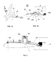
Figures 1 a and 1b show schematically the mechanical arrangement for operating the method for measuring the inertial properties of a movable, according to the present invention. -
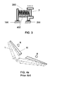
Figure 2 shows part of the components of the mechanical arrangement for operating the method for measuring the inertial properties of a movable, according to the present invention. -
Figure 3 shows a possible configuration of the elastic element in the mechanical arrangement for operating the method for measuring the inertial properties of a movable, according to the present invention. -
Figures 4a and4b show schematically a method for controlling the mass and the centre of gravity of a movable, according to the known prior art, using a hanging scale per hoisting point used, a crane and a sling. -
Figure 5 shows the counterweight in the mechanical arrangement for operating the method for measuring the inertial properties of a movable, according to the present invention. -
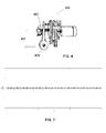
Figure 6 shows a detail of a possible configuration of a vibration generator having an eccentric mass rotating around an axis, in the mechanical arrangement for operating the method for measuring the inertial properties of a movable, according to the present invention. -
Figure 7 plots the angular position versus time of a movable assembly, which is the response when the excitation frequency in the method according to the invention is substantially far from the resonance frequency of the movable assembly. -
Figure 8 plots the angular position versus time of a movable assembly, which is the response when the excitation frequency in the method according to the invention is substantially close to the resonance frequency of the movable assembly. -
Figure 9 shows the principles underlying refining the static momentum of the movable and obtaining the frictional momentum of the movable in the method for measuring the inertial properties of a movable, according to the present invention. - Once the static momentum and the frictional momentum of a movable 10 in an
aircraft control surface 1 are determined, the method of the invention analyses the response to forced oscillations of said movable 10: in the Figures attached, the corresponding case of an elevator has been represented, where this movable 10 (elevator) rotates around ahinge line 2. - The
mechanical arrangement 20 for operating the above-mentioned method is schematically represented inFigures 1b and 2 , and it comprises: - a
first part 100 attached to the stabilizer, which is the fixed part of thecontrol surface 1, or to the ground, in order to provide a suitable point of anchorage; - a
second part 200 attached to the movable 10, such that thissecond part 200 together with the movable 10 form what is called throughout this description amovable assembly 40, thissecond part 200 comprising an adjustable counterweight 600 (that can be adjusted in height and also in length, by way of acting on a height adjustingdevice 601 and on a length adjustingdevice 602, respectively, as shown inFigure 5 ) amovement transducer 400, capturing the angular movement of themovable assembly 40, and avibration generator 500, generating forced oscillations on themovable assembly 40; and - an
elastic element 300, typically a spring, linking thefirst part 100 and thesecond part 200 in themechanical arrangement 20. - According to the invention, it should be desirable that the momentum of inertia of the
mechanical arrangement 20 around thehinge line 2 is minimised, for the sake of the accuracy of the results. - A possible embodiment of the
vibration generator 500 is shown inFigure 6 , comprising aneccentric mass 800, that rotates around anaxis 802, at a distance of 801. Different embodiments of thevibration generator 500 are also possible. - Both
parts elastic element 300, typically a spring having a known elastic constant and having an adjustable position by means of an adjustingdevice 3, as shown inFigure 3 . Theelastic element 300 is attached on one of its sides to thefirst part 100, and is attached on the other of its sides to thesecond part 200, theelastic element 300 being displaceable on one of its sides, therefore allowing the adjustment of the rest position of themechanical arrangement 20. - Each
control surface 1 item, typically an elevator, will have associated a specificelastic element 300, typically a spring, having an elastic constant that is chosen to produce a suitable resonance frequency of themovable assembly 40, typically 2 Hz. The adjustingdevice 3 allows the adjustment of themechanical arrangement 20 to the angular position of themovable assembly 40, therefore fixing the zero position for carrying out the method of the invention. Themovable assembly 40, after theelastic element 300 has been connected and once the balance has been performed, constitutes a second order mechanical system. This system has a resonance frequency which is a function of the elastic constant of theelastic element 300 and of the momentum of inertia of themovable assembly 40. As the elastic constant of theelastic element 300 is a function of a desirable resonance frequency that has been chosen, the real resonance frequency is unknown (to be determined) but will be very close to that used to obtain the elastic constant of theelastic element 300. - Typically, the
mechanical arrangement 20 is also connected to a computer (laptop) and some portable electric equipment, in order to analyse the data and carry out the method of the invention. - For the sake of clarity, although practical executions lead to different embodiments, the Figures attached to this Description show the main concepts underlying the invention. However, practical embodiments can be different from those represented in the Figures: for example, a preferred embodiment of the
mechanical arrangement 20 would entail that thevibration generator 500 is located on the left side of themechanical arrangement 20, and would be comprised within theadjustable counterweight 600 structure: the momentum of inertia of themovable assembly 40 is reduced, which improves the quality of the measurement. - The method proposed in this invention allows to adjust the frequency of the vibration generator 500: this frequency increases progressively (from a lower value than that of the resonance), until the maximum deflection of the movable 10 gets close to the admissible limits known for the
control surface 1, which indicates the close proximity to the resonance frequency of themovable assembly 40, as it will be further explained in detail. - The method of the invention is therefore directed towards the measurement of the inertial properties of the movable 10 of a
control surface 1, this movable 10 being typically an elevator, the method comprising the following steps: - a) incorporating the
second part 200 of themechanical arrangement 20 on thecontrol surface 1, thus configuring themovable assembly 40; - b) removing the mechanical connections of the actuators from the movable 10, leaving it free to rotate around its
hinge line 2; - c) balancing the
movable assembly 40 so that its centre of gravity 4 lays on the close neighbourhood of the hinge line 2 (coarse balancing); - d) calculating in a first approach the coarse static momentum of the movable 10;
- e) refining the coarse static momentum of the movable 10 obtained in d), and obtaining simultaneously the frictional momentum of the movable 10, which comprises the following steps:
- i) placing a known mass at a given distance p (see
Figure 9 ) to the right of thehinge line 2, progressively adding more of said known mass until the movable 10 overcomes the frictional band and starts rotating; - ii) entering the data of the total mass md used in step i) together with the distance p into the formula (3);
- iii) removing the total mass md and placing a known mass at a given distance q (see
Figure 9 ) to the left of thehinge line 2, progressively adding more of said known mass until the movable 10 overcomes the frictional band and starts rotating in the sense contrary to the rotation sense in i); - iv) entering the data of the total mass mi used in step iii) together with the distance q into the formula (4);
- v) calculating, using the formula (5), the increment of the static momentum (ΔM static = Wma.x) of the movable 10 that corrects the coarse static momentum calculated in previous step e);
- vi) calculating, using the formula (6) below, the frictional momentum Mf in the
hinge 2;


- i) placing a known mass at a given distance p (see
- f) performing an additional adjustment to fix the rest position of the
movable control surface 1, that is, the zeroes of the oscillating movement, by performing a tuning of the adjustingdevice 3 of theelastic element 300, such that this position is equidistant from the limits restricting the maximum movement (deflection) of the movable 10 on each of the two sides, being necessary that thefirst part 100 of themechanical arrangement 20, together with theelastic element 300, have been previously incorporated on the control surface1; - g) activating the
vibration generator 500; - h) acquiring the wave response (position angle versus time) of the
movable assembly 40, at a high rate, for example above 10000 samples/second, as well as the output of thevibration generator 500; - i) stopping the
vibration generator 500 after a time enough to obtain two lobes in the "beating" wave response of themovable assembly 40 obtained in h); - j) measuring the frequency of the first lobe (Wlobe), thus calculating, together with the output rotation frequency (Ωrot) of the
vibration generator 500, the real resonance frequency of the movable assembly 40 (Wreson), using the formula (1);
- k) obtaining from the resonance frequency (Wreson) in j) the momentum of inertia of the movable assembly 40 (Itot) according to (2);

- l) subtracting the contribution to the momentum of inertia of the components of the
mechanical arrangement 20 incorporated in a) to the momentum of inertia in k), thus obtaining the momentum of inertia of the movable 10. - In step h), the wave response (position angle versus time) of the
movable assembly 40 is acquired at a high rate, for example above 10000 samples/second: from this response, the frequency of the first lobe (Wlobe) is obtained. Also, in step h), the output of thevibration generator 500 is obtained: from this response, the output rotation frequency (Ωrot) of thevibration generator 500 is obtained. Preferably, a computer is used for acquiring and treating the wave response in h) and for calculating the frequency of the first lobe (Wlobe) and the output rotation frequency (Ωrot) of thevibration generator 500. -
Figure 7 shows the plotted response obtained in step h), showing the position angle versus time of themovable assembly 40, when the excitation frequency provided by thevibration generator 500 is far from the resonance frequency of themovable assembly 40. When the excitation frequency is very close to the resonance frequency, the type of response is that shown inFigure 8 : this response is suitable for obtaining the momentum of inertia of the movable assembly 40 (Itot). The period of the lobe (Wlobe), can thus be accurately measured, and entered in the formula (1) above. The protocol starts with a rotation frequency (Ωrot) of thevibration generator 500 lower than the expected resonance frequency of the movable assembly 40 (Wreson); the process is then repeated with frequencies of rotation (Ωrot) that are progressively higher; the different plotted responses are observed, until the maximum lobe amplitude approaches the maximum deflection allowed for the movable 10: at this stage, the rotation frequency (Ωrot) and the period of the lobe (Wlobe) are appropriate for being entered in the formula (1), where the value of the resonance frequency of the movable assembly 40 (Wreson) is calculated. - Furthermore, an additional advantage of the method of the invention is the simultaneous calculation of the frictional momentum of the movable 10 when rotating around the
hinge line 2, as cited in step e) above. For the calculation of the frictional momentum, themechanical arrangement 20 of thecontrol surface 1 is used without theelastic element 300. The centre of gravity of themovable assembly 40 would be aligned with thehinge line 2 if there existed no frictional momentum; as a small frictional momentum exists, this situation does not occur and the centre of gravity of themovable assembly 40 has a small offset with respect to thehinge line 2. - In a preferred embodiment of the invention, after step iv) mentioned above, the increment of the static momentum (ΔM static) of the movable 10 is calculated using the formula (5) above, as a first approach. This value of ΔM static is then used for refining the static momentum of the movable 10 (as cited in step e) above): an element having a mass calculated such that it provides a static momentum that neutralizes the static momentum of the movable 10, this element being located at a certain distance from the hinge line 2 (to the right side or the left side of the
hinge line 2, depending on the mathematical sign obtained from the formula (5)) is used for carrying out the rest of the method steps f) to l). The mathematic signs used are such that the positive sign corresponds to the elevator, rotating in a clockwise sense. - The concept of lobe used in the present invention disclosure will be explained in further detail now. When a mechanical system is excited with a frequency close to its natural resonance, its response follows a movement, angular in this case, as the one represented in
Figure 8 . The term lobe used in this description corresponds to a set of oscillations that starts with the zero level of the origin of one oscillation having minimum amplitude and finishes with the zero level of the end of the next oscillation having minimum amplitude: for example, inFigure 8 , there is only one of these lobes being shown. - Although the present invention has been described in connection with various embodiments, it will be appreciated from the specification that various combinations of elements, variations or improvements therein may be made, and are within the scope of the invention.
Claims (10)
- Method for obtaining the inertial properties of a movable (10) rotating around a hinge line (2) in an aircraft control surface (1), comprising the following steps:a) removing the actuators mechanical connections from the movable (10), leaving it free to rotate around its hinge line (2), further balancing the movable (10) and calculating in a first approach its coarse static momentum;b) refining the static momentum of the movable (10) obtained in a), and obtaining simultaneously its frictional momentum;c) incorporating an elastic element (300) on the control surface (1), configuring a second order mechanical system;d) inducing forced oscillations on the movable (10) at a certain frequency, this frequency being increased until it is sensibly close to the resonance frequency of the movable (10);e) calculating, from the wave response in d), the momentum of inertia of the movable (10).
- Method according to claim 1, characterized in that the forced oscillations induced in d) are produced at a frequency of around 2 Hz.
- Method according to any of claims 1-2, characterized in that the forced oscillations induced in d) are such that they provide a wave response of the movable (10) at a high rate, above 10000 samples/second.
- Method according to any of claims 1-3, characterized in that the refining of the static momentum of the movable (10) in step b) allowing obtaining simultaneously its frictional momentum, comprises the following steps:i) placing a known mass at a given distance to the right of the hinge line (2), progressively adding more of said known mass until the movable (10) overcomes the frictional band and starts rotating, with a value of the total mass of md;ii) removing the total mass md and placing a known mass to the left of the hinge line (2), progressively adding more of said known mass until the movable (10) overcomes the frictional band and starts rotating in the sense contrary to the rotation sense in i), with a value of the total mass of mi;iii) calculating the increment of the static momentum of the movable (10) that corrects the static momentum calculated in step b); calculating the frictional momentum in the hinge line (2).
- Mechanical arrangement (20) for an aircraft control surface (1), comprising:- a first part (100) attached to the stabilizer or to the ground, in order to provide a suitable point of anchorage;- a second part (200) attached to the movable (10) configuring a movable assembly (40), this second part (200) comprising an adjustable counterweight (600), a movement transducer (400) that captures the angular movement of the movable (10) and a vibration generator (500), that induces forced oscillations on the movable (10); and- an elastic element (300), linking the first part (100) and the second part (200) in the mechanical arrangement (20).
- Mechanical arrangement (20) according to claim 5, characterized in that the elastic element (300) has an elastic constant with a value such that it produces a desired resonance frequency of the movable assembly (40).
- Mechanical arrangement (20) according to any of claims 5-6, characterized in that the resonance frequency of the movable assembly (40) is around 2 Hz.
- Mechanical arrangement (20) according to any of claims 5-7, characterized in that the elastic element (300) is attached on one of its sides to the first part (100) and is attached on the other of its sides to the second part (200), the elastic element (300) being displaceable on one of its sides, in such a way that the adjustment of the rest position of the mechanical arrangement (20) is allowed.
- Mechanical arrangement (20) according to any of claims 5-8, characterized in that the vibration generator (500) is comprised within the adjustable counterweight (600) structure.
- Aircraft elevator comprising a mechanical arrangement (20) according to any of claims 5-9.
Priority Applications (4)
| Application Number | Priority Date | Filing Date | Title |
|---|---|---|---|
| ES12382293.4T ES2540935T3 (en) | 2012-07-20 | 2012-07-20 | Measurement of the inertial properties of a movable control surface |
| EP20120382293 EP2687445B1 (en) | 2012-07-20 | 2012-07-20 | Measurement of the inertial properties of an aircraft movable control surface |
| US13/845,310 US9067673B2 (en) | 2012-07-20 | 2013-03-18 | Measurement of the inertial properties of an aircraft movable control surface |
| CN201310305653.6A CN103575469B (en) | 2012-07-20 | 2013-07-19 | The measurement of the inertial property of the removable control surface of aircraft |
Applications Claiming Priority (1)
| Application Number | Priority Date | Filing Date | Title |
|---|---|---|---|
| EP20120382293 EP2687445B1 (en) | 2012-07-20 | 2012-07-20 | Measurement of the inertial properties of an aircraft movable control surface |
Publications (2)
| Publication Number | Publication Date |
|---|---|
| EP2687445A1 true EP2687445A1 (en) | 2014-01-22 |
| EP2687445B1 EP2687445B1 (en) | 2015-04-22 |
Family
ID=46982498
Family Applications (1)
| Application Number | Title | Priority Date | Filing Date |
|---|---|---|---|
| EP20120382293 Not-in-force EP2687445B1 (en) | 2012-07-20 | 2012-07-20 | Measurement of the inertial properties of an aircraft movable control surface |
Country Status (4)
| Country | Link |
|---|---|
| US (1) | US9067673B2 (en) |
| EP (1) | EP2687445B1 (en) |
| CN (1) | CN103575469B (en) |
| ES (1) | ES2540935T3 (en) |
Cited By (1)
| Publication number | Priority date | Publication date | Assignee | Title |
|---|---|---|---|---|
| CN113581489A (en) * | 2021-07-20 | 2021-11-02 | 中国民用航空飞行学院 | Static balance moment adjusting device and method for airplane control surface |
Families Citing this family (4)
| Publication number | Priority date | Publication date | Assignee | Title |
|---|---|---|---|---|
| RU2594462C1 (en) * | 2015-05-14 | 2016-08-20 | Федеральное государственное унитарное предприятие "Центральный аэрогидродинамический институт имени профессора Н.Е. Жуковского" (ФГУП "ЦАГИ") | Vibration exciter of oscillations of mechanical structures |
| US9499283B1 (en) * | 2015-06-15 | 2016-11-22 | The United States Of America As Represented By The Secretary Of The Navy | Freeplay measurement device |
| CN108995827B (en) * | 2018-07-03 | 2021-04-06 | 南京航空航天大学 | Method for rapidly acquiring weight, gravity center and rotational inertia of helicopter |
| CN114707370B (en) * | 2022-01-28 | 2024-07-12 | 北京航空航天大学 | Flight simulation method suitable for elastic aircraft |
Citations (3)
| Publication number | Priority date | Publication date | Assignee | Title |
|---|---|---|---|---|
| US2782631A (en) * | 1955-04-14 | 1957-02-26 | Hughes Aircraft Co | Center of weight distribution locator |
| US3416362A (en) * | 1966-09-22 | 1968-12-17 | Navy Usa | System for measuring moments of inertia |
| DE29622132U1 (en) * | 1996-12-23 | 1998-03-19 | KUKA Schweissanlagen GmbH, 86165 Augsburg | Measuring device for determining mass ratios |
Family Cites Families (5)
| Publication number | Priority date | Publication date | Assignee | Title |
|---|---|---|---|---|
| US3229934A (en) * | 1963-10-04 | 1966-01-18 | Vogtle Aircraft Corp | Control system for airplanes using weights for automatic stabilization |
| DE102005060779B4 (en) * | 2005-12-16 | 2008-07-10 | Eads Deutschland Gmbh | power generator |
| US7933691B2 (en) * | 2006-01-24 | 2011-04-26 | The Boeing Company | System for and method of monitoring free play of aircraft control surfaces |
| FR2908107B1 (en) * | 2006-11-06 | 2008-12-19 | Airbus France Sa | METHOD AND DEVICE FOR ESTIMATING THE FORCES EXERCISING ON A CONTROL SURFACE OF AN AIRCRAFT. |
| US8566054B1 (en) * | 2009-11-20 | 2013-10-22 | The Boeing Company | Aircraft control surface measurement |
-
2012
- 2012-07-20 ES ES12382293.4T patent/ES2540935T3/en active Active
- 2012-07-20 EP EP20120382293 patent/EP2687445B1/en not_active Not-in-force
-
2013
- 2013-03-18 US US13/845,310 patent/US9067673B2/en not_active Expired - Fee Related
- 2013-07-19 CN CN201310305653.6A patent/CN103575469B/en not_active Expired - Fee Related
Patent Citations (3)
| Publication number | Priority date | Publication date | Assignee | Title |
|---|---|---|---|---|
| US2782631A (en) * | 1955-04-14 | 1957-02-26 | Hughes Aircraft Co | Center of weight distribution locator |
| US3416362A (en) * | 1966-09-22 | 1968-12-17 | Navy Usa | System for measuring moments of inertia |
| DE29622132U1 (en) * | 1996-12-23 | 1998-03-19 | KUKA Schweissanlagen GmbH, 86165 Augsburg | Measuring device for determining mass ratios |
Cited By (1)
| Publication number | Priority date | Publication date | Assignee | Title |
|---|---|---|---|---|
| CN113581489A (en) * | 2021-07-20 | 2021-11-02 | 中国民用航空飞行学院 | Static balance moment adjusting device and method for airplane control surface |
Also Published As
| Publication number | Publication date |
|---|---|
| CN103575469A (en) | 2014-02-12 |
| US20140021294A1 (en) | 2014-01-23 |
| EP2687445B1 (en) | 2015-04-22 |
| CN103575469B (en) | 2017-06-16 |
| US9067673B2 (en) | 2015-06-30 |
| ES2540935T3 (en) | 2015-07-14 |
Similar Documents
| Publication | Publication Date | Title |
|---|---|---|
| EP2687445B1 (en) | Measurement of the inertial properties of an aircraft movable control surface | |
| Feldbusch et al. | Vibration analysis using mobile devices (smartphones or tablets) | |
| CN105527075A (en) | Method and apparatus of moment calibration for resonance fatigue test | |
| RU2596239C1 (en) | Method of vibroacoustic tests of specimens and models | |
| US20150219539A1 (en) | Method of determining the non-propagation threshold of fatigue cracks at high frequency | |
| RU2558679C1 (en) | Test rig for vibroacoustic tests of samples and models | |
| RU2603787C1 (en) | Test bench for vibroacoustic tests of specimens and models | |
| EP2444787A1 (en) | Method and device for bridge state evaluation using dynamic method | |
| CN107131984B (en) | A kind of random vibration test force measuring method | |
| JP2011027669A (en) | Vibration test apparatus and vibration test method | |
| D’Emilia et al. | Evaluation of aspects affecting measurement of three-axis accelerometers | |
| WO2016112335A1 (en) | High frequency displacement measurement correction | |
| RU2524743C2 (en) | Method for calibration of piezoelectric vibration transducer on operation site without dismantlement | |
| RU2362136C1 (en) | Method for impact testing of construction | |
| RU2613484C2 (en) | Method for determining tension force of cable-stayed element of bridge | |
| RU2009141787A (en) | METHOD FOR FORECASTING A VARIABLE COMPONENT OF THE ELECTROMECHANICAL ANGULAR SPEED SENSOR (DUS) OUTPUT SIGNAL FOR THE PRODUCTION OF ITS GYROMOTOR BY CHARACTERISTICS OF ANGULAR ANIMAL VIBRATIONS | |
| RU2489696C1 (en) | Method for determining free frequencies and generalised masses of vibrating structures | |
| US20230048801A1 (en) | Method and a system for estimating the tension of a tension member | |
| CN113390504A (en) | Low-frequency vibration sensor calibration system and calibration method | |
| EP1976760A1 (en) | System for and method of monitoring free play of aircraft control surfaces | |
| CN106289688B (en) | The test method of antiskid brake control device vibratory response | |
| Yatsun et al. | Experimental study into rotational-oscillatory vibrations of a vibration machine platform excited by the ball auto-balancer | |
| RU2775360C1 (en) | Method for determining the dynamic characteristics of flexible extended structures by experiment | |
| Miller | Seismic noise analysis and isolation concepts for the ALPS II experiment at DESY | |
| RU2674408C1 (en) | Method for determining voltages in an oscillating blade |
Legal Events
| Date | Code | Title | Description |
|---|---|---|---|
| PUAI | Public reference made under article 153(3) epc to a published international application that has entered the european phase |
Free format text: ORIGINAL CODE: 0009012 |
|
| AK | Designated contracting states |
Kind code of ref document: A1 Designated state(s): AL AT BE BG CH CY CZ DE DK EE ES FI FR GB GR HR HU IE IS IT LI LT LU LV MC MK MT NL NO PL PT RO RS SE SI SK SM TR |
|
| AX | Request for extension of the european patent |
Extension state: BA ME |
|
| RBV | Designated contracting states (corrected) |
Designated state(s): AL AT BE BG CH CY CZ DE DK EE ES FI FR GB GR HR HU IE IS IT LI LT LU LV MC MK MT NL NO PL PT RO RS SE SI SK SM TR |
|
| 17P | Request for examination filed |
Effective date: 20140714 |
|
| GRAP | Despatch of communication of intention to grant a patent |
Free format text: ORIGINAL CODE: EPIDOSNIGR1 |
|
| INTG | Intention to grant announced |
Effective date: 20141127 |
|
| GRAS | Grant fee paid |
Free format text: ORIGINAL CODE: EPIDOSNIGR3 |
|
| GRAA | (expected) grant |
Free format text: ORIGINAL CODE: 0009210 |
|
| AK | Designated contracting states |
Kind code of ref document: B1 Designated state(s): AL AT BE BG CH CY CZ DE DK EE ES FI FR GB GR HR HU IE IS IT LI LT LU LV MC MK MT NL NO PL PT RO RS SE SI SK SM TR |
|
| REG | Reference to a national code |
Ref country code: GB Ref legal event code: FG4D |
|
| REG | Reference to a national code |
Ref country code: CH Ref legal event code: EP |
|
| REG | Reference to a national code |
Ref country code: AT Ref legal event code: REF Ref document number: 723061 Country of ref document: AT Kind code of ref document: T Effective date: 20150515 |
|
| REG | Reference to a national code |
Ref country code: IE Ref legal event code: FG4D |
|
| REG | Reference to a national code |
Ref country code: DE Ref legal event code: R096 Ref document number: 602012006853 Country of ref document: DE Effective date: 20150603 |
|
| REG | Reference to a national code |
Ref country code: FR Ref legal event code: PLFP Year of fee payment: 4 |
|
| REG | Reference to a national code |
Ref country code: ES Ref legal event code: FG2A Ref document number: 2540935 Country of ref document: ES Kind code of ref document: T3 Effective date: 20150714 |
|
| REG | Reference to a national code |
Ref country code: NL Ref legal event code: VDEP Effective date: 20150422 |
|
| REG | Reference to a national code |
Ref country code: AT Ref legal event code: MK05 Ref document number: 723061 Country of ref document: AT Kind code of ref document: T Effective date: 20150422 |
|
| REG | Reference to a national code |
Ref country code: LT Ref legal event code: MG4D |
|
| PG25 | Lapsed in a contracting state [announced via postgrant information from national office to epo] |
Ref country code: NL Free format text: LAPSE BECAUSE OF FAILURE TO SUBMIT A TRANSLATION OF THE DESCRIPTION OR TO PAY THE FEE WITHIN THE PRESCRIBED TIME-LIMIT Effective date: 20150422 |
|
| PG25 | Lapsed in a contracting state [announced via postgrant information from national office to epo] |
Ref country code: PT Free format text: LAPSE BECAUSE OF FAILURE TO SUBMIT A TRANSLATION OF THE DESCRIPTION OR TO PAY THE FEE WITHIN THE PRESCRIBED TIME-LIMIT Effective date: 20150824 Ref country code: NO Free format text: LAPSE BECAUSE OF FAILURE TO SUBMIT A TRANSLATION OF THE DESCRIPTION OR TO PAY THE FEE WITHIN THE PRESCRIBED TIME-LIMIT Effective date: 20150722 Ref country code: HR Free format text: LAPSE BECAUSE OF FAILURE TO SUBMIT A TRANSLATION OF THE DESCRIPTION OR TO PAY THE FEE WITHIN THE PRESCRIBED TIME-LIMIT Effective date: 20150422 Ref country code: LT Free format text: LAPSE BECAUSE OF FAILURE TO SUBMIT A TRANSLATION OF THE DESCRIPTION OR TO PAY THE FEE WITHIN THE PRESCRIBED TIME-LIMIT Effective date: 20150422 Ref country code: FI Free format text: LAPSE BECAUSE OF FAILURE TO SUBMIT A TRANSLATION OF THE DESCRIPTION OR TO PAY THE FEE WITHIN THE PRESCRIBED TIME-LIMIT Effective date: 20150422 |
|
| PG25 | Lapsed in a contracting state [announced via postgrant information from national office to epo] |
Ref country code: AT Free format text: LAPSE BECAUSE OF FAILURE TO SUBMIT A TRANSLATION OF THE DESCRIPTION OR TO PAY THE FEE WITHIN THE PRESCRIBED TIME-LIMIT Effective date: 20150422 Ref country code: IS Free format text: LAPSE BECAUSE OF FAILURE TO SUBMIT A TRANSLATION OF THE DESCRIPTION OR TO PAY THE FEE WITHIN THE PRESCRIBED TIME-LIMIT Effective date: 20150822 Ref country code: RS Free format text: LAPSE BECAUSE OF FAILURE TO SUBMIT A TRANSLATION OF THE DESCRIPTION OR TO PAY THE FEE WITHIN THE PRESCRIBED TIME-LIMIT Effective date: 20150422 Ref country code: GR Free format text: LAPSE BECAUSE OF FAILURE TO SUBMIT A TRANSLATION OF THE DESCRIPTION OR TO PAY THE FEE WITHIN THE PRESCRIBED TIME-LIMIT Effective date: 20150723 Ref country code: LV Free format text: LAPSE BECAUSE OF FAILURE TO SUBMIT A TRANSLATION OF THE DESCRIPTION OR TO PAY THE FEE WITHIN THE PRESCRIBED TIME-LIMIT Effective date: 20150422 |
|
| REG | Reference to a national code |
Ref country code: DE Ref legal event code: R097 Ref document number: 602012006853 Country of ref document: DE |
|
| PG25 | Lapsed in a contracting state [announced via postgrant information from national office to epo] |
Ref country code: DK Free format text: LAPSE BECAUSE OF FAILURE TO SUBMIT A TRANSLATION OF THE DESCRIPTION OR TO PAY THE FEE WITHIN THE PRESCRIBED TIME-LIMIT Effective date: 20150422 Ref country code: EE Free format text: LAPSE BECAUSE OF FAILURE TO SUBMIT A TRANSLATION OF THE DESCRIPTION OR TO PAY THE FEE WITHIN THE PRESCRIBED TIME-LIMIT Effective date: 20150422 |
|
| PLBE | No opposition filed within time limit |
Free format text: ORIGINAL CODE: 0009261 |
|
| STAA | Information on the status of an ep patent application or granted ep patent |
Free format text: STATUS: NO OPPOSITION FILED WITHIN TIME LIMIT |
|
| PG25 | Lapsed in a contracting state [announced via postgrant information from national office to epo] |
Ref country code: RO Free format text: LAPSE BECAUSE OF NON-PAYMENT OF DUE FEES Effective date: 20150422 Ref country code: SK Free format text: LAPSE BECAUSE OF FAILURE TO SUBMIT A TRANSLATION OF THE DESCRIPTION OR TO PAY THE FEE WITHIN THE PRESCRIBED TIME-LIMIT Effective date: 20150422 Ref country code: CZ Free format text: LAPSE BECAUSE OF FAILURE TO SUBMIT A TRANSLATION OF THE DESCRIPTION OR TO PAY THE FEE WITHIN THE PRESCRIBED TIME-LIMIT Effective date: 20150422 Ref country code: MC Free format text: LAPSE BECAUSE OF FAILURE TO SUBMIT A TRANSLATION OF THE DESCRIPTION OR TO PAY THE FEE WITHIN THE PRESCRIBED TIME-LIMIT Effective date: 20150422 Ref country code: PL Free format text: LAPSE BECAUSE OF FAILURE TO SUBMIT A TRANSLATION OF THE DESCRIPTION OR TO PAY THE FEE WITHIN THE PRESCRIBED TIME-LIMIT Effective date: 20150422 |
|
| REG | Reference to a national code |
Ref country code: CH Ref legal event code: PL |
|
| 26N | No opposition filed |
Effective date: 20160125 |
|
| PG25 | Lapsed in a contracting state [announced via postgrant information from national office to epo] |
Ref country code: LU Free format text: LAPSE BECAUSE OF FAILURE TO SUBMIT A TRANSLATION OF THE DESCRIPTION OR TO PAY THE FEE WITHIN THE PRESCRIBED TIME-LIMIT Effective date: 20150720 |
|
| REG | Reference to a national code |
Ref country code: IE Ref legal event code: MM4A |
|
| PG25 | Lapsed in a contracting state [announced via postgrant information from national office to epo] |
Ref country code: CH Free format text: LAPSE BECAUSE OF NON-PAYMENT OF DUE FEES Effective date: 20150731 Ref country code: LI Free format text: LAPSE BECAUSE OF NON-PAYMENT OF DUE FEES Effective date: 20150731 Ref country code: IT Free format text: LAPSE BECAUSE OF FAILURE TO SUBMIT A TRANSLATION OF THE DESCRIPTION OR TO PAY THE FEE WITHIN THE PRESCRIBED TIME-LIMIT Effective date: 20150422 |
|
| PG25 | Lapsed in a contracting state [announced via postgrant information from national office to epo] |
Ref country code: SI Free format text: LAPSE BECAUSE OF FAILURE TO SUBMIT A TRANSLATION OF THE DESCRIPTION OR TO PAY THE FEE WITHIN THE PRESCRIBED TIME-LIMIT Effective date: 20150422 |
|
| REG | Reference to a national code |
Ref country code: FR Ref legal event code: PLFP Year of fee payment: 5 |
|
| PG25 | Lapsed in a contracting state [announced via postgrant information from national office to epo] |
Ref country code: IE Free format text: LAPSE BECAUSE OF NON-PAYMENT OF DUE FEES Effective date: 20150720 |
|
| PG25 | Lapsed in a contracting state [announced via postgrant information from national office to epo] |
Ref country code: BE Free format text: LAPSE BECAUSE OF FAILURE TO SUBMIT A TRANSLATION OF THE DESCRIPTION OR TO PAY THE FEE WITHIN THE PRESCRIBED TIME-LIMIT Effective date: 20150422 |
|
| PG25 | Lapsed in a contracting state [announced via postgrant information from national office to epo] |
Ref country code: MT Free format text: LAPSE BECAUSE OF FAILURE TO SUBMIT A TRANSLATION OF THE DESCRIPTION OR TO PAY THE FEE WITHIN THE PRESCRIBED TIME-LIMIT Effective date: 20150422 |
|
| PG25 | Lapsed in a contracting state [announced via postgrant information from national office to epo] |
Ref country code: SM Free format text: LAPSE BECAUSE OF FAILURE TO SUBMIT A TRANSLATION OF THE DESCRIPTION OR TO PAY THE FEE WITHIN THE PRESCRIBED TIME-LIMIT Effective date: 20150422 Ref country code: BG Free format text: LAPSE BECAUSE OF FAILURE TO SUBMIT A TRANSLATION OF THE DESCRIPTION OR TO PAY THE FEE WITHIN THE PRESCRIBED TIME-LIMIT Effective date: 20150422 Ref country code: HU Free format text: LAPSE BECAUSE OF FAILURE TO SUBMIT A TRANSLATION OF THE DESCRIPTION OR TO PAY THE FEE WITHIN THE PRESCRIBED TIME-LIMIT; INVALID AB INITIO Effective date: 20120720 |
|
| PG25 | Lapsed in a contracting state [announced via postgrant information from national office to epo] |
Ref country code: SE Free format text: LAPSE BECAUSE OF FAILURE TO SUBMIT A TRANSLATION OF THE DESCRIPTION OR TO PAY THE FEE WITHIN THE PRESCRIBED TIME-LIMIT Effective date: 20150422 Ref country code: CY Free format text: LAPSE BECAUSE OF FAILURE TO SUBMIT A TRANSLATION OF THE DESCRIPTION OR TO PAY THE FEE WITHIN THE PRESCRIBED TIME-LIMIT Effective date: 20150422 |
|
| REG | Reference to a national code |
Ref country code: FR Ref legal event code: PLFP Year of fee payment: 6 |
|
| PGFP | Annual fee paid to national office [announced via postgrant information from national office to epo] |
Ref country code: ES Payment date: 20170825 Year of fee payment: 6 |
|
| PG25 | Lapsed in a contracting state [announced via postgrant information from national office to epo] |
Ref country code: MK Free format text: LAPSE BECAUSE OF FAILURE TO SUBMIT A TRANSLATION OF THE DESCRIPTION OR TO PAY THE FEE WITHIN THE PRESCRIBED TIME-LIMIT Effective date: 20150422 Ref country code: TR Free format text: LAPSE BECAUSE OF FAILURE TO SUBMIT A TRANSLATION OF THE DESCRIPTION OR TO PAY THE FEE WITHIN THE PRESCRIBED TIME-LIMIT Effective date: 20150422 |
|
| REG | Reference to a national code |
Ref country code: FR Ref legal event code: PLFP Year of fee payment: 7 |
|
| PG25 | Lapsed in a contracting state [announced via postgrant information from national office to epo] |
Ref country code: AL Free format text: LAPSE BECAUSE OF FAILURE TO SUBMIT A TRANSLATION OF THE DESCRIPTION OR TO PAY THE FEE WITHIN THE PRESCRIBED TIME-LIMIT Effective date: 20150422 |
|
| PGFP | Annual fee paid to national office [announced via postgrant information from national office to epo] |
Ref country code: DE Payment date: 20180723 Year of fee payment: 7 Ref country code: FR Payment date: 20180725 Year of fee payment: 7 |
|
| PGFP | Annual fee paid to national office [announced via postgrant information from national office to epo] |
Ref country code: GB Payment date: 20180719 Year of fee payment: 7 |
|
| REG | Reference to a national code |
Ref country code: ES Ref legal event code: FD2A Effective date: 20190917 |
|
| PG25 | Lapsed in a contracting state [announced via postgrant information from national office to epo] |
Ref country code: ES Free format text: LAPSE BECAUSE OF NON-PAYMENT OF DUE FEES Effective date: 20180721 |
|
| REG | Reference to a national code |
Ref country code: DE Ref legal event code: R119 Ref document number: 602012006853 Country of ref document: DE |
|
| GBPC | Gb: european patent ceased through non-payment of renewal fee |
Effective date: 20190720 |
|
| PG25 | Lapsed in a contracting state [announced via postgrant information from national office to epo] |
Ref country code: DE Free format text: LAPSE BECAUSE OF NON-PAYMENT OF DUE FEES Effective date: 20200201 Ref country code: GB Free format text: LAPSE BECAUSE OF NON-PAYMENT OF DUE FEES Effective date: 20190720 |
|
| PG25 | Lapsed in a contracting state [announced via postgrant information from national office to epo] |
Ref country code: FR Free format text: LAPSE BECAUSE OF NON-PAYMENT OF DUE FEES Effective date: 20190731 |