US9499283B1 - Freeplay measurement device - Google Patents

Freeplay measurement device Download PDF

Info

Publication number
US9499283B1
US9499283B1 US14/739,244 US201514739244A US9499283B1 US 9499283 B1 US9499283 B1 US 9499283B1 US 201514739244 A US201514739244 A US 201514739244A US 9499283 B1 US9499283 B1 US 9499283B1
Authority
US
United States
Prior art keywords
aft
ruddervator
tail
assembly
shaped bracket
Prior art date
Legal status (The legal status is an assumption and is not a legal conclusion. Google has not performed a legal analysis and makes no representation as to the accuracy of the status listed.)
Expired - Fee Related, expires
Application number
US14/739,244
Other versions
US20160362196A1 (en
Inventor
Anthony Olszewski
Current Assignee (The listed assignees may be inaccurate. Google has not performed a legal analysis and makes no representation or warranty as to the accuracy of the list.)
US Department of Navy
Original Assignee
US Department of Navy
Priority date (The priority date is an assumption and is not a legal conclusion. Google has not performed a legal analysis and makes no representation as to the accuracy of the date listed.)
Filing date
Publication date
Application filed by US Department of Navy filed Critical US Department of Navy
Priority to US14/739,244 priority Critical patent/US9499283B1/en
Assigned to DEPARTMENT OF THE NAVY reassignment DEPARTMENT OF THE NAVY ASSIGNMENT OF ASSIGNORS INTEREST (SEE DOCUMENT FOR DETAILS). Assignors: OLSZEWSKI, ANTHONY
Application granted granted Critical
Publication of US9499283B1 publication Critical patent/US9499283B1/en
Publication of US20160362196A1 publication Critical patent/US20160362196A1/en
Expired - Fee Related legal-status Critical Current
Adjusted expiration legal-status Critical

Links

Images

Classifications

    • GPHYSICS
    • G01MEASURING; TESTING
    • G01MTESTING STATIC OR DYNAMIC BALANCE OF MACHINES OR STRUCTURES; TESTING OF STRUCTURES OR APPARATUS, NOT OTHERWISE PROVIDED FOR
    • G01M5/00Investigating the elasticity of structures, e.g. deflection of bridges or air-craft wings
    • G01M5/0016Investigating the elasticity of structures, e.g. deflection of bridges or air-craft wings of aircraft wings or blades
    • B64F5/0045
    • BPERFORMING OPERATIONS; TRANSPORTING
    • B64AIRCRAFT; AVIATION; COSMONAUTICS
    • B64FGROUND OR AIRCRAFT-CARRIER-DECK INSTALLATIONS SPECIALLY ADAPTED FOR USE IN CONNECTION WITH AIRCRAFT; DESIGNING, MANUFACTURING, ASSEMBLING, CLEANING, MAINTAINING OR REPAIRING AIRCRAFT, NOT OTHERWISE PROVIDED FOR; HANDLING, TRANSPORTING, TESTING OR INSPECTING AIRCRAFT COMPONENTS, NOT OTHERWISE PROVIDED FOR
    • B64F5/00Designing, manufacturing, assembling, cleaning, maintaining or repairing aircraft, not otherwise provided for; Handling, transporting, testing or inspecting aircraft components, not otherwise provided for
    • B64F5/60Testing or inspecting aircraft components or systems
    • GPHYSICS
    • G01MEASURING; TESTING
    • G01LMEASURING FORCE, STRESS, TORQUE, WORK, MECHANICAL POWER, MECHANICAL EFFICIENCY, OR FLUID PRESSURE
    • G01L5/00Apparatus for, or methods of, measuring force, work, mechanical power, or torque, specially adapted for specific purposes
    • G01L5/22Apparatus for, or methods of, measuring force, work, mechanical power, or torque, specially adapted for specific purposes for measuring the force applied to control members, e.g. control members of vehicles, triggers
    • GPHYSICS
    • G01MEASURING; TESTING
    • G01MTESTING STATIC OR DYNAMIC BALANCE OF MACHINES OR STRUCTURES; TESTING OF STRUCTURES OR APPARATUS, NOT OTHERWISE PROVIDED FOR
    • G01M5/00Investigating the elasticity of structures, e.g. deflection of bridges or air-craft wings
    • G01M5/0041Investigating the elasticity of structures, e.g. deflection of bridges or air-craft wings by determining deflection or stress
    • G01M5/005Investigating the elasticity of structures, e.g. deflection of bridges or air-craft wings by determining deflection or stress by means of external apparatus, e.g. test benches or portable test systems
    • BPERFORMING OPERATIONS; TRANSPORTING
    • B64AIRCRAFT; AVIATION; COSMONAUTICS
    • B64CAEROPLANES; HELICOPTERS
    • B64C13/00Control systems or transmitting systems for actuating flying-control surfaces, lift-increasing flaps, air brakes, or spoilers
    • B64C13/24Transmitting means
    • B64C13/26Transmitting means without power amplification or where power amplification is irrelevant
    • B64C13/28Transmitting means without power amplification or where power amplification is irrelevant mechanical
    • GPHYSICS
    • G01MEASURING; TESTING
    • G01BMEASURING LENGTH, THICKNESS OR SIMILAR LINEAR DIMENSIONS; MEASURING ANGLES; MEASURING AREAS; MEASURING IRREGULARITIES OF SURFACES OR CONTOURS
    • G01B21/00Measuring arrangements or details thereof, where the measuring technique is not covered by the other groups of this subclass, unspecified or not relevant
    • G01B21/16Measuring arrangements or details thereof, where the measuring technique is not covered by the other groups of this subclass, unspecified or not relevant for measuring distance of clearance between spaced objects

Definitions

  • Freeplay can be defined, but without limitation, as the positional or rotational variation in mechanical parts. All aircraft include movable control surfaces for directional control during flight. Control surfaces, which are movable, include, but without limitation, the rudder, the aileron, the elevator, and the all-moveable horizontal tail of an aircraft. These control surfaces, particularly those operated in a military environment must be monitored for the freeplay of the control system. Excessive freeplay can result in flutter, vibrations, fatigue, divergence, or other instabilities. Historically, freeplay testing involves using complex ground fixtures. This testing is time consuming, requires a large team, and is very expensive.
  • Freeplay is typically tested by applying a known load to the control surface and measuring the corresponding deflection. This is repeated over numerous different loads (both positive and negative) for a minimum of three cycles.
  • a rotational variable differential transformer is used to measure rotation between a rudder and a tail of an aircraft, while a test hydraulic actuator and a load cell are used to record the load.
  • Such setups are labor intensive and take a significant amount of time.
  • a ruddervator may be defined, but without limitation, as a pair of control surfaces on a v-tail design that perform the function of both a rudder and an elevator.
  • the present invention is directed to a system with the needs enumerated above and below.
  • the present invention is directed to a freeplay measurement device for measuring freeplay in a ruddervator.
  • the measurement device includes a forward horseshoe assembly, an aft horseshoe assembly, a L-shaped locator, a connecting assembly, a load applicator, and a measuring device.
  • the forward horseshoe assembly forms a half of an ellipse that can slip on the forward half of the tail.
  • the aft horseshoe assembly forms a half of an ellipse that can slip on the aft half of the tail and ruddervator.
  • the L-shaped locator is for aligning the forward horseshoe assembly on the tail and perpendicularly extends from the forward horseshoe assembly.
  • the connecting assembly connects the forward horseshoe assembly and the aft horseshoe assembly when each is placed over the tail and the ruddervator.
  • the load applicator is for applying loads on the ruddervator.
  • the measuring device is for measuring the deflections of the ruddervator being tested, and is attached to the forward horseshoe assembly.
  • FIG. 1 is an exploded side perspective view of the freeplay measurement device
  • FIG. 2 is a side perspective view of the freeplay measurement device
  • FIG. 3 is another perspective view of the freeplay measurement device.
  • FIGS. 4 a and 4 b are perspective views of the freeplay measurement device in operation.
  • a typical aircraft has a tail 50 with a forward half 51 and an aft half 52 .
  • An aircraft may also have a ruddervator 80 located at the aft half 52 of the tail 50 .
  • a freeplay measurement device 10 for measuring freeplay in a ruddervator 80 of an aircraft comprises of a forward horseshoe assembly 100 , an aft horseshoe assembly 200 , a L-shaped locator 600 , a connecting assembly 300 , a load applicator 400 , and a measuring device 700 .
  • the forward horseshoe assembly 100 has a first forward u-shaped bracket 110 , a second forward u-shaped bracket 120 , and a plurality of forward support braces 500 .
  • the plurality of forward support braces 500 connect the first forward u-shaped bracket 110 and the second forward u-shaped bracket 120 such that the first forward u-shaped bracket 110 and the second forward u-shaped bracket 120 form a half of an ellipse that can slip on the forward half 51 of the tail 50 .
  • the forward part of the forward horseshoe assembly 100 may include a forward support brace 550 that includes a polycarbonate contact surface.
  • the forward support brace 550 connects the first forward u-shaped bracket 110 and the second forward u-shaped bracket 120 to ensure proper positioning on the leading edge of the tail 50 being tested.
  • the aft horseshoe assembly 200 has a first aft u-shaped bracket 210 , a second aft u-shaped bracket 220 , and at least one aft support brace 505 .
  • the aft support brace 505 connects the first aft u-shaped bracket 210 and the second aft u-shaped bracket 220 such that the first aft u-shaped bracket 210 and the second aft u-shaped bracket 220 form a half of an ellipse that can slip on the aft half 52 of the tail 50 and the ruddervator 80 .
  • the L-shaped locator 600 is for vertically locating and aligning the forward horseshoe assembly 100 on the tail 50 .
  • the locator 600 perpendicularly extends from the first forward u-shaped bracket 110 .
  • the connecting assembly 300 can connect the forward horseshoe assembly 100 and the aft horseshoe assembly 200 when each is placed over the tail 50 and the ruddervator 80 .
  • the load applicator 400 is for applying loads on the ruddervator 80 , and the load applicator 400 is attached to the aft horseshoe assembly 200 .
  • the measuring device 700 is for measuring the deflections of the ruddervator 80 being tested, and is attached to the forward horseshoe assembly 100 (particularly the second forward u-shaped bracket 120 ).
  • the load applicator 400 can be a machine screw jack apparatus with a jack screw 451 and a load handle 452 for increasing or decreasing the load.
  • the load applicator (or machine screw jack apparatus) 400 may be attached to the aft horseshoe assembly 200 (particularly to both the first aft u-shaped bracket 210 and the second aft u-shaped bracket 220 ) via a jack mount assembly 453 .
  • the jack mount assembly 453 may be a bracket that connects the two aft u-shaped brackets 210 , 220 and has an area for attaching the load applicator 400 .
  • the load applicator 400 can include a ruddervator bracket 455 that communicates with the ruddervator 80 being tested (via a load indicator gauge 776 ) such that load is applied to the ruddervator 80 .
  • the load applicator 400 may also include a digital load indicator 454 which indicates the load being put on the ruddervator 80 .
  • the freeplay measuring device 10 may also include at least one clamp assembly 775 .
  • the clamp assembly 775 is at least one clamp attached to a forward support brace 500 that secures the device 10 to the tail 50 and the ruddervator 80 .
  • Two of the support braces 500 opposite the two clamp assemblies 775 have a polycarbonate contact surface 575 attached in such a way as to provide a sufficient clamp force from the clamp assemblies 775 and so that the tail 50 being tested is not damaged.
  • the measuring device 700 may be two id-c indicators that are attached to the forward horseshoe assembly 100 via a measuring device bracket 705 and can be connected to the forward horseshoe assembly 100 via measuring device screws 706 .
  • a tail 50 typically includes a tip 55 and a mass balance 60 .
  • the forward horseshoe assembly 100 is positioned until the L-shaped locator 600 corresponds with the tip 55 of the tail 50 and is positioned under the mass balance 60 of the tail 50 .
  • the aft horseshoe assembly 200 is slipped over the back end of the ruddervator 80 , aligned with the forward horseshoe assembly 100 , and the ruddervator bracket 455 is aligned with the ruddervator 80 .
  • the aft horseshoe assembly 200 is attached to the forward horseshoe assembly 100 using the connecting assembly 300 .
  • the connecting assembly 300 may be eight connecting assembly screws. However, any type of connecting assembly that is practicable may be utilized.
  • the clamp assembly 775 is then engaged in order to secure the device 10 to the tail 50 and the ruddervator 80 .
  • the measuring device 700 (which includes two dial indicators) is then attached to the forward horseshoe assembly 100 using the measuring device bracket 705 and three measuring device screws 706 .
  • the load applicator 400 is then engaged and a load is applied to the ruddervator 80 .
  • the load handle 452 is turned until the desired load is achieved by reading the digital load gage indicator 454 .
  • the corresponding deflections, as observed on the two dial indicators are recorded with the load. This process is done in increments of 10% of the maximum desired load until 100% is achieved.
  • the load handle 452 is turned in the opposite direction such as to incrementally unload the control surface. This is done in 10% increments until the maximum negative load is achieved. For each step the load and corresponding deflections are recorded.
  • the load handle 452 is then turned in the original direction in increments of 10% until zero load is achieved all the while recording load and deflections. This process is repeated a minimum of three times to ensure repeatability.

Abstract

A freeplay measurement device for measuring freeplay in a ruddervator includes a forward horseshoe assembly, an aft horseshoe assembly, a L-shaped locator, a connecting assembly, a load applicator, and a measuring device. The forward horseshoe assembly forms a half of an ellipse that can slip on the forward half of the tail. The aft horseshoe assembly forms a half of an ellipse that can slip on the aft half of the tail and ruddervator. The L-shaped locator is for aligning the forward horseshoe assembly on the tail and perpendicularly extends from the forward horseshoe assembly. The connecting assembly connects the forward horseshoe assembly and the aft horseshoe assembly when each is placed over the tail and the ruddervator. The load applicator is for applying loads on the ruddervator. The measuring device is for measuring the deflections of the ruddervator being tested, and is attached to the forward horseshoe assembly.

Description

STATEMENT OF GOVERNMENT INTEREST
The invention described herein may be manufactured and used by or for the Government of the United States of America for governmental purposes without payment of any royalties thereon or therefor.
BACKGROUND
Freeplay can be defined, but without limitation, as the positional or rotational variation in mechanical parts. All aircraft include movable control surfaces for directional control during flight. Control surfaces, which are movable, include, but without limitation, the rudder, the aileron, the elevator, and the all-moveable horizontal tail of an aircraft. These control surfaces, particularly those operated in a military environment must be monitored for the freeplay of the control system. Excessive freeplay can result in flutter, vibrations, fatigue, divergence, or other instabilities. Historically, freeplay testing involves using complex ground fixtures. This testing is time consuming, requires a large team, and is very expensive.
Freeplay is typically tested by applying a known load to the control surface and measuring the corresponding deflection. This is repeated over numerous different loads (both positive and negative) for a minimum of three cycles. For example, a rotational variable differential transformer is used to measure rotation between a rudder and a tail of an aircraft, while a test hydraulic actuator and a load cell are used to record the load. Such setups are labor intensive and take a significant amount of time.
The latest United States Navy program requires that a freeplay test be performed after every flight. This adds excessive cost and time to aircraft maintenance. Therefore, an alternative method to test freeplay of control surfaces is needed. In particular, there is a need to test the free play of a ruddervator. A ruddervator may be defined, but without limitation, as a pair of control surfaces on a v-tail design that perform the function of both a rudder and an elevator.
SUMMARY
The present invention is directed to a system with the needs enumerated above and below.
The present invention is directed to a freeplay measurement device for measuring freeplay in a ruddervator. The measurement device includes a forward horseshoe assembly, an aft horseshoe assembly, a L-shaped locator, a connecting assembly, a load applicator, and a measuring device. The forward horseshoe assembly forms a half of an ellipse that can slip on the forward half of the tail. The aft horseshoe assembly forms a half of an ellipse that can slip on the aft half of the tail and ruddervator. The L-shaped locator is for aligning the forward horseshoe assembly on the tail and perpendicularly extends from the forward horseshoe assembly. The connecting assembly connects the forward horseshoe assembly and the aft horseshoe assembly when each is placed over the tail and the ruddervator. The load applicator is for applying loads on the ruddervator. The measuring device is for measuring the deflections of the ruddervator being tested, and is attached to the forward horseshoe assembly.
It is a feature of the present invention to provide a freeplay measurement device that is easy to use and is inexpensive.
It is a feature of the present invention to provide a freeplay measurement device that can measure freeplay quickly, and utilize less than two people.
It is a feature of the present invention to provide a freeplay measurement device that does not require use of hydraulics or complex computer programs.
DRAWINGS
These and other features, aspects and advantages of the present invention will become better understood with reference to the following description and appended claims, and accompanying drawings wherein:
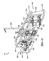
FIG. 1 is an exploded side perspective view of the freeplay measurement device;
FIG. 2 is a side perspective view of the freeplay measurement device;
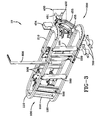
FIG. 3 is another perspective view of the freeplay measurement device; and,
FIGS. 4a and 4b are perspective views of the freeplay measurement device in operation.
DESCRIPTION
The preferred embodiments of the present invention are illustrated by way of example below and in FIGS. 1-4. As shown in FIGS. 4a and 4b , a typical aircraft has a tail 50 with a forward half 51 and an aft half 52. An aircraft may also have a ruddervator 80 located at the aft half 52 of the tail 50. As shown in FIG. 1, a freeplay measurement device 10 for measuring freeplay in a ruddervator 80 of an aircraft comprises of a forward horseshoe assembly 100, an aft horseshoe assembly 200, a L-shaped locator 600, a connecting assembly 300, a load applicator 400, and a measuring device 700. The forward horseshoe assembly 100 has a first forward u-shaped bracket 110, a second forward u-shaped bracket 120, and a plurality of forward support braces 500. The plurality of forward support braces 500 connect the first forward u-shaped bracket 110 and the second forward u-shaped bracket 120 such that the first forward u-shaped bracket 110 and the second forward u-shaped bracket 120 form a half of an ellipse that can slip on the forward half 51 of the tail 50. The forward part of the forward horseshoe assembly 100 may include a forward support brace 550 that includes a polycarbonate contact surface. The forward support brace 550 connects the first forward u-shaped bracket 110 and the second forward u-shaped bracket 120 to ensure proper positioning on the leading edge of the tail 50 being tested. The aft horseshoe assembly 200 has a first aft u-shaped bracket 210, a second aft u-shaped bracket 220, and at least one aft support brace 505. The aft support brace 505 connects the first aft u-shaped bracket 210 and the second aft u-shaped bracket 220 such that the first aft u-shaped bracket 210 and the second aft u-shaped bracket 220 form a half of an ellipse that can slip on the aft half 52 of the tail 50 and the ruddervator 80. The L-shaped locator 600 is for vertically locating and aligning the forward horseshoe assembly 100 on the tail 50. The locator 600 perpendicularly extends from the first forward u-shaped bracket 110. The connecting assembly 300 can connect the forward horseshoe assembly 100 and the aft horseshoe assembly 200 when each is placed over the tail 50 and the ruddervator 80. The load applicator 400 is for applying loads on the ruddervator 80, and the load applicator 400 is attached to the aft horseshoe assembly 200. The measuring device 700 is for measuring the deflections of the ruddervator 80 being tested, and is attached to the forward horseshoe assembly 100 (particularly the second forward u-shaped bracket 120).
As seen in FIGS. 1 and 2, in the preferred embodiment, the load applicator 400 can be a machine screw jack apparatus with a jack screw 451 and a load handle 452 for increasing or decreasing the load. However, any type of load applicator that is practicable can be utilized. The load applicator (or machine screw jack apparatus) 400 may be attached to the aft horseshoe assembly 200 (particularly to both the first aft u-shaped bracket 210 and the second aft u-shaped bracket 220) via a jack mount assembly 453. The jack mount assembly 453 may be a bracket that connects the two aft u-shaped brackets 210, 220 and has an area for attaching the load applicator 400. The load applicator 400 can include a ruddervator bracket 455 that communicates with the ruddervator 80 being tested (via a load indicator gauge 776) such that load is applied to the ruddervator 80. The load applicator 400 may also include a digital load indicator 454 which indicates the load being put on the ruddervator 80.
The freeplay measuring device 10 may also include at least one clamp assembly 775. The clamp assembly 775 is at least one clamp attached to a forward support brace 500 that secures the device 10 to the tail 50 and the ruddervator 80. Two of the support braces 500 opposite the two clamp assemblies 775 have a polycarbonate contact surface 575 attached in such a way as to provide a sufficient clamp force from the clamp assemblies 775 and so that the tail 50 being tested is not damaged.
As seen in FIG. 1, the measuring device 700 may be two id-c indicators that are attached to the forward horseshoe assembly 100 via a measuring device bracket 705 and can be connected to the forward horseshoe assembly 100 via measuring device screws 706.
Typically, a tail 50 includes a tip 55 and a mass balance 60. In the preferred operation, as seen in FIGS. 4A and 4B, the forward horseshoe assembly 100 is positioned until the L-shaped locator 600 corresponds with the tip 55 of the tail 50 and is positioned under the mass balance 60 of the tail 50. The aft horseshoe assembly 200 is slipped over the back end of the ruddervator 80, aligned with the forward horseshoe assembly 100, and the ruddervator bracket 455 is aligned with the ruddervator 80. In other embodiments, there may be multiple ruddervator brackets 455 for equal distribution of load on the ruddervator 80. Once each horseshoe assembly 100, 200 is positioned over the tail 50 and the ruddervator 80, the aft horseshoe assembly 200 is attached to the forward horseshoe assembly 100 using the connecting assembly 300. As shown in FIGS. 1 and 2, the connecting assembly 300 may be eight connecting assembly screws. However, any type of connecting assembly that is practicable may be utilized. The clamp assembly 775 is then engaged in order to secure the device 10 to the tail 50 and the ruddervator 80. The measuring device 700 (which includes two dial indicators) is then attached to the forward horseshoe assembly 100 using the measuring device bracket 705 and three measuring device screws 706. The load applicator 400 is then engaged and a load is applied to the ruddervator 80. The load handle 452 is turned until the desired load is achieved by reading the digital load gage indicator 454. The corresponding deflections, as observed on the two dial indicators are recorded with the load. This process is done in increments of 10% of the maximum desired load until 100% is achieved. Then the load handle 452 is turned in the opposite direction such as to incrementally unload the control surface. This is done in 10% increments until the maximum negative load is achieved. For each step the load and corresponding deflections are recorded. The load handle 452 is then turned in the original direction in increments of 10% until zero load is achieved all the while recording load and deflections. This process is repeated a minimum of three times to ensure repeatability.
In the description of the present invention, the invention will be discussed in a military aircraft environment; however, this invention can be utilized for any type of application that requires use of a freeplay measurement device.
When introducing elements of the present invention or the preferred embodiment(s) thereof, the articles “a,” “an,” “the,” and “said” are intended to mean there are one or more of the elements. The terms “comprising,” “including,” and “having” are intended to be inclusive and mean that there may be additional elements other than the listed elements.
Although the present invention has been described in considerable detail with reference to certain preferred embodiments thereof, other embodiments are possible. Therefore, the spirit and scope of the appended claims should not be limited to the description of the preferred embodiment(s) contained, herein.

Claims (1)

What is claimed is:
1. A freeplay measurement device for measuring freeplay in a ruddervator of an aircraft, the aircraft having a tail, the ruddervator attached to the tail, the tail having a forward half and an aft half, the device comprising:
a forward horseshoe assembly comprising a first forward u-shaped bracket, a second forward u-shaped bracket, and at least one forward support brace, the at least one forward support brace connecting the first forward u-shaped bracket and the second forward u-shaped bracket such that the first forward u-shaped bracket and the second forward u-shaped bracket form a half of an ellipse that can slip on the forward half of the tail;
an aft horseshoe assembly comprising a first aft u-shaped bracket, a second aft u-shaped bracket, at least one aft support brace, the at least one aft support brace connecting the first aft u-shaped bracket and the second aft u-shaped bracket such that the first aft u-shaped bracket and the second aft u-shaped bracket form a half of an ellipse that can slip on the aft half of the tail and the ruddervator;
a L-shaped locator for vertically locating and aligning the forward horseshoe assembly on the tail, the locator perpendicularly extending from the first forward u-shaped bracket;
a connecting assembly that can connect the forward horseshoe assembly and the aft horseshoe assembly when each is placed over the tail and the ruddervator;
a load applicator for applying loads on the ruddervator, the load applicator attached to the aft horseshoe assembly; and
a measuring device for measuring the deflections of the ruddervator being tested, the measuring device attached to the forward horseshoe assembly.
US14/739,244 2015-06-15 2015-06-15 Freeplay measurement device Expired - Fee Related US9499283B1 (en)

Priority Applications (1)

Application Number Priority Date Filing Date Title
US14/739,244 US9499283B1 (en) 2015-06-15 2015-06-15 Freeplay measurement device

Applications Claiming Priority (1)

Application Number Priority Date Filing Date Title
US14/739,244 US9499283B1 (en) 2015-06-15 2015-06-15 Freeplay measurement device

Publications (2)

Publication Number Publication Date
US9499283B1 true US9499283B1 (en) 2016-11-22
US20160362196A1 US20160362196A1 (en) 2016-12-15

Family

ID=57287627

Family Applications (1)

Application Number Title Priority Date Filing Date
US14/739,244 Expired - Fee Related US9499283B1 (en) 2015-06-15 2015-06-15 Freeplay measurement device

Country Status (1)

Country Link
US (1) US9499283B1 (en)

Cited By (3)

* Cited by examiner, † Cited by third party
Publication number Priority date Publication date Assignee Title
CN113071706A (en) * 2021-03-31 2021-07-06 成都飞机工业(集团)有限责任公司 Aircraft control surface clearance measuring device
CN113879560A (en) * 2021-11-13 2022-01-04 四川凌峰航空液压机械有限公司 Method for measuring movable clearance of internal lock of airplane actuator cylinder
CN116986015A (en) * 2023-09-28 2023-11-03 航天江南集团有限公司 Steering engine detection device

Families Citing this family (1)

* Cited by examiner, † Cited by third party
Publication number Priority date Publication date Assignee Title
WO2018145173A1 (en) 2017-02-09 2018-08-16 Embraer S.A. Device and method for adjusting aircraft control surfaces

Citations (6)

* Cited by examiner, † Cited by third party
Publication number Priority date Publication date Assignee Title
US20070173988A1 (en) * 2006-01-24 2007-07-26 Pitt Dale M System for and method of monitoring free play of aircraft control surfaces
US20090166475A1 (en) * 2007-12-27 2009-07-02 Airbus Deutschland Gmbh Apparatus for the pivotal fastening of an active surface, in particular a spoiler on a wind tunnel model of an aircraft
US8032269B2 (en) * 2007-05-18 2011-10-04 Sikorsky Aircraft Corporation Control surface failure detection for fly-by-wire aircraft
US8727272B2 (en) * 2011-03-23 2014-05-20 Airbus Operations Gmbh Apparatus for adjusting a surface of an aircraft model, surface unit, aircraft model, and use of an aircraft model
US9067673B2 (en) * 2012-07-20 2015-06-30 Airbus Operations S.L. Measurement of the inertial properties of an aircraft movable control surface
US20160041050A1 (en) * 2014-08-11 2016-02-11 Embraer S.A. Testing apparatus, systems and methods for statically determining free play of aircraft control surfaces

Patent Citations (7)

* Cited by examiner, † Cited by third party
Publication number Priority date Publication date Assignee Title
US20070173988A1 (en) * 2006-01-24 2007-07-26 Pitt Dale M System for and method of monitoring free play of aircraft control surfaces
US7933691B2 (en) * 2006-01-24 2011-04-26 The Boeing Company System for and method of monitoring free play of aircraft control surfaces
US8032269B2 (en) * 2007-05-18 2011-10-04 Sikorsky Aircraft Corporation Control surface failure detection for fly-by-wire aircraft
US20090166475A1 (en) * 2007-12-27 2009-07-02 Airbus Deutschland Gmbh Apparatus for the pivotal fastening of an active surface, in particular a spoiler on a wind tunnel model of an aircraft
US8727272B2 (en) * 2011-03-23 2014-05-20 Airbus Operations Gmbh Apparatus for adjusting a surface of an aircraft model, surface unit, aircraft model, and use of an aircraft model
US9067673B2 (en) * 2012-07-20 2015-06-30 Airbus Operations S.L. Measurement of the inertial properties of an aircraft movable control surface
US20160041050A1 (en) * 2014-08-11 2016-02-11 Embraer S.A. Testing apparatus, systems and methods for statically determining free play of aircraft control surfaces

Cited By (5)

* Cited by examiner, † Cited by third party
Publication number Priority date Publication date Assignee Title
CN113071706A (en) * 2021-03-31 2021-07-06 成都飞机工业(集团)有限责任公司 Aircraft control surface clearance measuring device
CN113879560A (en) * 2021-11-13 2022-01-04 四川凌峰航空液压机械有限公司 Method for measuring movable clearance of internal lock of airplane actuator cylinder
CN113879560B (en) * 2021-11-13 2023-09-26 四川凌峰航空液压机械有限公司 Method for measuring movable clearance of inner lock of aircraft actuating cylinder
CN116986015A (en) * 2023-09-28 2023-11-03 航天江南集团有限公司 Steering engine detection device
CN116986015B (en) * 2023-09-28 2023-12-12 航天江南集团有限公司 Steering engine detection device

Also Published As

Publication number Publication date
US20160362196A1 (en) 2016-12-15

Similar Documents

Publication Publication Date Title
US9499283B1 (en) Freeplay measurement device
CN109238630B (en) Rod balance calibration device and calibration method
US20170211999A1 (en) Force/torque sensor having redundant instrumentation and operative to detect faults
US8505388B2 (en) Apparatus and method for simulating lifetime of and/or stress experienced by a rotor blade and rotor disc fixture
US8789423B2 (en) High frequency vibration system
CN108168774B (en) Space vector force calibration method
CN206223464U (en) Steering wheel integrated test system for performance
JP2013142698A (en) System and method for aligning test object with load
US9410864B2 (en) Method and device for determining the static unbalance
CN108369092A (en) Method and system for the trueness error for compensating six sufficient instrument
US20190128770A1 (en) Method of fatigue testing a complex structure
CN104897392A (en) Auricle loaded test method and loading system
KR101381569B1 (en) Thrust measuring system for high altitude simulation test with diffuser and the thrust measuring method
US11371923B2 (en) Automatic system compliance estimation and correction for mechanical testing systems
Bauer et al. Development and validation of an on-wing engine thrust measurement system
Sharma et al. Analysis of stresses and strains in a rotating homogeneous thermoelastic circular disk by using finite element method
EP3578945A1 (en) Method of fatigue testing a complex structure
CN112478197A (en) Dynamic measurement method for clearance of airplane control surface
CN110480547B (en) Control surface clamping tool and method and system for determining locking function of electromagnetic lock
CN109580139B (en) Servo valve armature subassembly comprehensive rigidity testing arrangement
CN108982041B (en) Air rudder core excitation testing device
US5596133A (en) Rotating peel fixture
US2472108A (en) Thrust gauge for projectiles
Mohan et al. Development of RLV-TD Stage Separation System
US3040435A (en) Testing machines

Legal Events

Date Code Title Description
AS Assignment

Owner name: DEPARTMENT OF THE NAVY, MARYLAND

Free format text: ASSIGNMENT OF ASSIGNORS INTEREST;ASSIGNOR:OLSZEWSKI, ANTHONY;REEL/FRAME:035837/0388

Effective date: 20150612

STCF Information on status: patent grant

Free format text: PATENTED CASE

FEPP Fee payment procedure

Free format text: MAINTENANCE FEE REMINDER MAILED (ORIGINAL EVENT CODE: REM.); ENTITY STATUS OF PATENT OWNER: LARGE ENTITY

LAPS Lapse for failure to pay maintenance fees

Free format text: PATENT EXPIRED FOR FAILURE TO PAY MAINTENANCE FEES (ORIGINAL EVENT CODE: EXP.); ENTITY STATUS OF PATENT OWNER: LARGE ENTITY

STCH Information on status: patent discontinuation

Free format text: PATENT EXPIRED DUE TO NONPAYMENT OF MAINTENANCE FEES UNDER 37 CFR 1.362

FP Lapsed due to failure to pay maintenance fee

Effective date: 20201122