EP2687399A1 - Dispositif de suspension d'un câble porteur de caténaire - Google Patents
Dispositif de suspension d'un câble porteur de caténaire Download PDFInfo
- Publication number
- EP2687399A1 EP2687399A1 EP13176736.0A EP13176736A EP2687399A1 EP 2687399 A1 EP2687399 A1 EP 2687399A1 EP 13176736 A EP13176736 A EP 13176736A EP 2687399 A1 EP2687399 A1 EP 2687399A1
- Authority
- EP
- European Patent Office
- Prior art keywords
- cable
- cable support
- hinge ring
- fixing rod
- suspension device
- Prior art date
- Legal status (The legal status is an assumption and is not a legal conclusion. Google has not performed a legal analysis and makes no representation as to the accuracy of the status listed.)
- Withdrawn
Links
- 239000000725 suspension Substances 0.000 claims abstract description 38
- OKTJSMMVPCPJKN-UHFFFAOYSA-N Carbon Chemical compound [C] OKTJSMMVPCPJKN-UHFFFAOYSA-N 0.000 claims description 5
- 229910002804 graphite Inorganic materials 0.000 claims description 5
- 239000010439 graphite Substances 0.000 claims description 5
- 229910045601 alloy Inorganic materials 0.000 claims description 4
- 239000000956 alloy Substances 0.000 claims description 4
- 229910000906 Bronze Inorganic materials 0.000 claims description 3
- 230000007797 corrosion Effects 0.000 description 6
- 238000005260 corrosion Methods 0.000 description 6
- 230000003137 locomotive effect Effects 0.000 description 3
- 239000000463 material Substances 0.000 description 3
- 229910000497 Amalgam Inorganic materials 0.000 description 2
- 230000008878 coupling Effects 0.000 description 2
- 238000010168 coupling process Methods 0.000 description 2
- 238000005859 coupling reaction Methods 0.000 description 2
- 238000006073 displacement reaction Methods 0.000 description 2
- 238000005461 lubrication Methods 0.000 description 2
- 238000012423 maintenance Methods 0.000 description 2
- 229910052751 metal Inorganic materials 0.000 description 2
- 239000002184 metal Substances 0.000 description 2
- 229910001220 stainless steel Inorganic materials 0.000 description 2
- 239000010935 stainless steel Substances 0.000 description 2
- 229910000838 Al alloy Inorganic materials 0.000 description 1
- 208000031968 Cadaver Diseases 0.000 description 1
- 229910000881 Cu alloy Inorganic materials 0.000 description 1
- NINIDFKCEFEMDL-UHFFFAOYSA-N Sulfur Chemical compound [S] NINIDFKCEFEMDL-UHFFFAOYSA-N 0.000 description 1
- 229910052782 aluminium Inorganic materials 0.000 description 1
- 230000015572 biosynthetic process Effects 0.000 description 1
- 239000013043 chemical agent Substances 0.000 description 1
- 239000011247 coating layer Substances 0.000 description 1
- 230000007613 environmental effect Effects 0.000 description 1
- 230000006353 environmental stress Effects 0.000 description 1
- 239000007789 gas Substances 0.000 description 1
- 238000009434 installation Methods 0.000 description 1
- 230000001050 lubricating effect Effects 0.000 description 1
- 239000000203 mixture Substances 0.000 description 1
- 230000010355 oscillation Effects 0.000 description 1
- 230000000284 resting effect Effects 0.000 description 1
- 229910001256 stainless steel alloy Inorganic materials 0.000 description 1
- 230000035882 stress Effects 0.000 description 1
- 239000000126 substance Substances 0.000 description 1
- 238000006467 substitution reaction Methods 0.000 description 1
- 229910052717 sulfur Inorganic materials 0.000 description 1
- 239000011593 sulfur Substances 0.000 description 1
- -1 trademark CN8 ® Inorganic materials 0.000 description 1
- 238000009827 uniform distribution Methods 0.000 description 1
- 230000000007 visual effect Effects 0.000 description 1
- 230000003313 weakening effect Effects 0.000 description 1
Images


Classifications
-
- B—PERFORMING OPERATIONS; TRANSPORTING
- B60—VEHICLES IN GENERAL
- B60M—POWER SUPPLY LINES, AND DEVICES ALONG RAILS, FOR ELECTRICALLY- PROPELLED VEHICLES
- B60M1/00—Power supply lines for contact with collector on vehicle
- B60M1/12—Trolley lines; Accessories therefor
- B60M1/20—Arrangements for supporting or suspending trolley wires, e.g. from buildings
-
- B—PERFORMING OPERATIONS; TRANSPORTING
- B60—VEHICLES IN GENERAL
- B60M—POWER SUPPLY LINES, AND DEVICES ALONG RAILS, FOR ELECTRICALLY- PROPELLED VEHICLES
- B60M1/00—Power supply lines for contact with collector on vehicle
- B60M1/12—Trolley lines; Accessories therefor
- B60M1/20—Arrangements for supporting or suspending trolley wires, e.g. from buildings
- B60M1/24—Clamps; Splicers; Anchor tips
Definitions
- the present invention relates to the field of railway installations and, more particularly, that of equipment for supplying electrical power to locomotives traveling on the tracks.
- a wire called contact wire In order to transmit electrical power to trains running on a railway line, a wire called contact wire is disposed above the railway. It feeds current pantographs that are located on the top of the locomotive. A pantograph is a device that allows an electric locomotive to capture the current by friction on the contact wire.
- support posts are arranged, from time to time, along the track. They each comprise a contact wire holding system comprising a stay and a console, placed cantilevered with respect to the support post and arranged to form a triangle in a vertical plane at the top of the pole .
- LCS Single Contact Line
- the capture of the current at high speeds (greater than 110km / h) requires that the single line of contact offers adequate flexibility. At conventional speeds, this lack of flexibility will cause totally degraded capture which will result in arcing that will damage the contact wire and cause its rupture. And above all, at high speed, the pantograph and thread can not be assured.
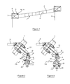
- a known solution, illustrated by figure 1 is to suspend the contact wire 1 to a carrier cable 2 which is itself suspended from each post 4 through the holding system 3 and which takes an arcuate shape between two posts 4 consecutive.
- the contact wire 1 is then suspended from the carrying cable 2 by means of a succession of vertical cables 5, called pendulums, whose lengths are adapted to maintain the contact wire 1 substantially horizontal between the posts 4.
- the assembly formed by the contact wire 1, the carrying cable 2 and the pendulums 5 is called catenary (or Air Line Contact).
- the catenary support system 3 comprises a stay 6, a console 7 and a suspension device 10 arranged to connect the stay 6, the console 7 and the carrying cable 2.
- Two known suspension devices 10a and 10b respectively illustrated by the Figures 2 and 3 , each comprise a fastening piece 12 of the stay 6 and the console 7 and a cable support 20 comprising a receiving portion 21 of rounded or bent cross section forming a groove in which the support cable 2 rests, the support 20 being connected to the attachment piece 12 by a universal joint 14.
- two U-shaped brackets 22 are positioned astride the carrying cable 2 on either side of the support 20 and fixed thereto by four sets 24 of screws and nuts.
- the receiving portion 21 is in the form of a hook whose concavity is turned upwards to receive a carrier cable of small diameter, for example a bare cable.
- the branches of the stirrups 22 are oriented along a horizontal axis XX perpendicular to the horizontal axis along which the carrier cable 2 extends.
- the receiving portion 21 is in the form of a gutter arranged to receive a carrier cable of larger diameter, for example a protected cable comprising a coating layer, and the branches of the stirrups 22 are oriented according to an axis vertical YY perpendicular to the horizontal axis along which the carrier cable 2 extends.
- each gimbal 14 of the suspension devices 10a, 10b is adapted to allow, on the one hand, a displacement along a first axis of horizontal rotation A parallel to the axis along which the carrier cable 2 extends, and on the other hand, a displacement along a second axis of horizontal rotation B perpendicular to the axis along which the carrier cable 2 extends.
- the attachment piece 12 comprises, at its lower end, two yoke arms each having a through hole.
- the upper end of the gimbal 14 has an ear, not shown mounted between the yoke arm of the fastener 12 to allow the passage of a first fastening rod 18 extending along the axis A.
- the gimbal 14 comprises, at its lower end, two yoke arms each having a through hole.
- the upper end of the cable support 20 has an lug 23 mounted between the yoke arms of the gimbal 14 to allow the passage of a second fastening rod 19 extending along the axis B.
- the fastener 12, the gimbal 14 and the cable support 20 are made of cupro-aluminum alloy while the fixing rods 18 and 19 are made of stainless steel.
- such joints have several drawbacks as to the quality of the connection.
- joints are frequently subject to atmospheric pollution, for example sulfur released by exhaust gases or plants, and / or weather conditions, such as rain and heat, which may eventually contribute to accelerate corrosion and reduce the effectiveness of the pivot connection, for example by causing seizure of the joint, which has a second drawback.
- atmospheric pollution for example sulfur released by exhaust gases or plants
- weather conditions such as rain and heat
- the present invention aims to remedy at least in part these disadvantages by providing a suspension device of a carrier cable which is both simple, easy to assemble and resistant to physical and chemical constraints to which it may be exposed.
- the subject of the invention is a device for suspending a catenary carrying cable over a railway line comprising a fastener adapted to be connected to a pole and a cable support, arranged to supporting the carrier cable, which is hinged to the fastener around a horizontal axis of rotation by means of a fixing rod.
- the device is remarkable in that a hinge ring is mounted at the upper end of the cable holder so as to isolate the cable holder from the fastening rod.
- Such a hinge ring makes it possible to avoid direct contact between the cable support and the fixing rod while nevertheless allowing their relative rotation, which makes it possible to absorb a part of the forces transmitted during the passage of a pantograph or under the action of the wind.
- the hinge ring forms an interface between the cable support and the fixing rod which are thus no longer in direct contact.
- the friction zone of the hinge is no longer directly between the cable support and the fixing rod but between the hinge ring and the fixing rod, preventing corrosion by electrolytic coupling.
- the cable support and the fastening rod can thus be constituted respectively of cupro-aluminum and stainless steel without their electrolytic coupling generating corrosion. The effectiveness of such a device thus makes it possible to carry out maintenance less frequently.
- the mounting of the cable support on the attachment piece reduces the number of components of the suspension device since it is no longer necessary to use a gimbal between the two elements.
- the cable support is directly connected to the attachment piece by the fixing rod.
- directly is meant that there is no intermediate piece connecting the cable support and the attachment part other than the fixing rod and the hinge ring. There is no, for example, cardan connecting the cable support and the attachment part.
- the cable support is articulated to the attachment piece around a single axis of rotation. The removal of the prior art gimbal further reduces the number of pivot connections since only one pivot connection is used between the cable support and the attachment part instead of two, thus eliminating the need for a pivot connection. pivot connection without functional input in the suspension device.
- the hinge ring is integral with the cable holder, so that the hinge is relatively between the hinge ring and the fixing rod.
- the cable support comprises, at its upper end, a connecting lug inside which the hinge ring extends, for example forcibly mounted in the connecting lug, the rod fastener being mounted coaxially in the hinge ring.
- the hinge ring may be in the form of a longitudinal piece of length substantially equal to that of the hinge cylinder.
- the length of the hinge ring is less than the length of the fastening rod.
- the fulcrum ring is made of a copper alloy, e.g., trademark CN8 ®, or a stainless steel alloy or a bronze alloy, preferably with inserts graphite and / or at least one seal, preferably two seals.
- This latter composition offers good resistance to mechanical, climatic or environmental stresses to which the articulation between the cable support and the fixing rod can be subjected.
- the graphite inserts provide a low coefficient of friction on the surface of the ring, they are maintenance-free and are particularly used in applications of intermittent oscillations involving high loads and making difficult the formation of any lubricating film (enduring without lubrication, low coefficient of friction, load high, resistance to wear, corrosion and chemical agents).
- the ring can be subjected to high temperatures outside, the metal can heat up to about 80 ° C.
- Graphite shows no loss, unlike oil, and can rise or fall in temperature without losing its lubrication qualities.
- the attachment piece comprises, at its end of connection to the cable support, a yoke comprising means for locking the fastening rod relative to the fastening piece of in order to prevent rotation of the fastening rod relative to the fastener.
- a yoke comprising means for locking the fastening rod relative to the fastening piece of in order to prevent rotation of the fastening rod relative to the fastener.
- Such locking in rotation avoids the friction and mechanical stress of the fastening rod on the yoke which could lead to weakening, including the screed, or the creation of a corrosive and abrasive amalgam between the fastening rod and the screed.
- the locking means may also allow locking in translation of the fixing rod relative to the yoke so that the rod remains secured to the yoke.
- the locking means comprise a protrusion and a pin, the protrusion and the fixing rod being traversed by the pin in the locking position of the rod.
- the invention also relates to an assembly comprising a suspension device, as defined above, and a carrying cable disposed and held in the cable holder of the suspension device by the clamping clamp.
- the fixing rod is substantially parallel to the axis along which the carrier cable extends. Lateral swinging of the suspension device is thus made possible when the carrier cable moves under the action of an external force such as the wind or the passage of a pantograph.
- the single pivot connection between the attachment piece and the cable support allows the suspension device to withstand forces of up to 773 daN, for example such as those caused by mounting installed to support a catenary type LGV (High Speed Line).
- the invention further relates to a system for holding a catenary carrying cable over a railway line comprising a stay and a console adapted to be mounted on a pole and a suspension device as defined above, the attachment piece is connected to the stay and the console.
- the figure 1 represents the suspension of a catenary comprising a contact wire 1 and a carrying cable 2.
- the contact wire 1 is suspended from the carrying cable 2 by a plurality of pendulums 5.
- the carrying cable 2 is suspended at each pole 4 disposed along of the railway track by a holding system 3.
- the carrying cable 2 extends horizontally along an axis ZZ illustrated in FIG. figure 5 .
- Such a holding system 3 comprises a stay 6, a console 7 and a suspension device 11 arranged to connect the stay 6, the console 7 and the carrying cable 2.
- the stay 6 is disposed substantially horizontally between the post 4 and the suspension device 11 along an axis WW parallel to the horizontal axis XX, orthogonal to the axis ZZ along which the carrier cable 2 extends.
- the console 7 is arranged obliquely between the pole 4 and the suspension device 11 so as to form, with the stay 6, a triangle for holding the suspension device 11 to the pole 4 extending in a plane transverse to the axis ZZ according to which the carrier cable 2 extends.
- the suspension device 11 according to the invention illustrated by the Figures 4 and 5 comprises a fastening piece 12, connecting the stay 6 and the console 7, and a cable support 30, connected to the attachment piece 12, in which the carrying cable 2 is arranged.
- the attachment part 12 comprises a cover 12a and a body 12b. Subsequently, the terms “lower” and “upper” are used relative to a suspension device 11 in the position of use in a holding system 3 of a catenary suspended over a railway.
- the cover 12a is arranged, on the one hand, to receive an attachment end of the stay 6 and, on the other hand, to maintain a portion of the console 7 by cooperation with the body 12b by means of a control system.
- stirrups 13a and nuts 13b as will be detailed later.
- Each stirrup 13a is in the form of a U-shaped piece whose threaded ends are fixed on the body 12b by the nuts 13b.
- the cover 12a comprises, at its upper part, a yoke 15 having two orifices passing therethrough and arranged to receive a fixing rod 16a of the stay 6 held by a pin 16b.
- the cover 12a comprises, in its lower part, a rounded portion arranged to receive a portion of the console 7 of circular section.
- the body 12b comprises, in its upper part, a rounded portion 17a arranged to receive a portion of the console 7 of circular section.
- the cover 12a and the body 12b can hold firmly the portion of the console 7 by complementarity of shapes.
- the console 7 is secured between the cover 12a and the body 12b by two stirrups 13a U-shaped surrounding the cover 12a and fixed at the upper part of the body 12b by the nuts 13b.
- the body 12b further comprises, at its lower part, a yoke 17c of connection with the cable support 30 connected to the rounded portion 17a by a connecting arm 17b, as illustrated by the figures 5 and 6 .
- the yoke 17c comprises two orifices 17d crossing on each side arranged to receive a fastening rod 25 and a receiving protrusion 17e of a pin 26 for holding the fastening rod 25.
- the receiving protrusion 17e comprises a receiving orifice 17f of the pin 26.
- the fixing rod 25 likewise comprises a receiving orifice, not shown, of the pin 26.
- the cable support 30 of the suspension device 11 is directly mounted on the attachment piece 12 by a pivot connection of horizontal axis comprising the rod of 25 and the pin 26, as illustrated by the Figures 4 and 5 .
- the cable support 30 is in the form of a bent arm 31 having substantially the shape of a C.
- the arm 31 is fixed at its upper end 32, being in the form of a connecting lug at the connecting yoke 17c via the fixing rod 25 and the pin 26 as illustrated in FIG. figure 5 .
- the arm 31 comprises, at its lower part, a channel 34 configured to receive the carrier cable 2.
- the channel 34 has a substantially V-shaped section whose opening is about 90 ° and is configured to receive cables of different diameters.
- the channel 34 extends in the direction ZZ along which the carrier cable 2 extends, that is to say, parallel to the fixing rod 25.
- the length of the channel 34 is greater than the width of the arm 31 defined along the axis ZZ so as to provide a distributed holding force on the carrying cable 2.
- the arm 31 and the trough 34 are arranged so that the axis of the carrying cable 2 and the fixing rod 25 of the cable support 30 on the fastener 12 are substantially in the same vertical plane YY.
- the cable support 30 of the suspension device 11 further comprises a platform 36 arranged to receive a clamping flange 40 of the carrying cable 2 illustrated by the Figures 4 and 5 .
- the platform 36 extends substantially parallel to a horizontal axis XX, that is to say, perpendicular to the axis ZZ along which the carrier cable 2 extends.
- the clamp 40 illustrated by the Figures 4 and 5 is in the form of a longitudinal piece, preferably made of metal, having an attachment end 41 connected to the platform 36 and a free end resting on the carrying cable 2 to pinch it to hold it in the gutter 34.
- the clamping flange 40 comprises an arcuate holding portion 42 arranged to be positioned on the periphery of the carrying cable 2 so as to conform to its shape and limit its movement. For this purpose, the curvature of the arcuate holding portion is adapted to that of the carrying cable 2.
- the fixing end 41 comprises a receiving orifice, not shown, of a screw 50 and a stop 44 for supporting the clamping flange 40 on the platform 36.
- the clamping flange 40 is fixed on the platform 36 at the end. its fixing end level by a system comprising the screw 50, a spherical bearing washer 52 and a nut 54.
- the spherical bearing washer 52 ensures a uniform distribution of the clamping on the platform 36 and the carrier cable 2 by self-centering the screw 50.
- the width of the clamping flange 40 is substantially equal to that of the platform 36 and that of the arm 32.
- the clamping flange 40 is housed in abutment in a recess 46 formed in the gutter 34 so as to be locked in translation in the direction of the axis ZZ of the carrier cable 2.
- the clamping flange 40 is not driven by the carrier cable 2 if it undergoes a movement along the axis ZZ.
- the upper end of the cable support 30 is in the form of a hinge cylinder 32 within which extends, coaxially, a hinge ring 60, for example mounted by force.
- the hinge ring 60 is in the form of a longitudinal piece of length substantially equal to that of the hinge cylinder 32. Preferably, the length of the hinge ring 60 is less than the length of the hinge pin. fixing 25.
- the hinge ring 60 is made of a steel-stainless alloy, or a bronze alloy, for example with graphite inserts and two seals, or even a cuprous alloy, for example CN8 ® trademark.
- the hinge ring 60 comprises, ends 62 whose edges are flared, which allows to easily insert the hinge ring 60 in the hinge cylinder 32.
- the hinge ring 60 is a friction ring called "wear” configured to allow friction.
- the hinge ring 60 serves as an interface between two non-electrolytically compatible materials.
- the hinge ring 60 gives the suspension device 11 a long duration of use, for example, greater than 15 years, so that the maintenance of the suspension device 11 can be performed less often.
- the hinge ring 60 can be changed after wear, its change can be carried out, for example, by a press fitting of the substitution hinge ring which expels the worn hinge ring.
- the cable support 30 of the suspension device 11 has a visual cue in the form of a window, a depth of about 1 mm, inked on both sides of the articulation cylinder 32.
- This mark 32a becomes visible when the hinge ring 60 reaches a certain level of wear, indicating that it should be changed.
- the hinge cylinder 32 When mounting the cable support 30 on the fastener 12, the hinge cylinder 32 is first disposed coaxially in the axis of the through-holes 17d of the arms of the yoke 17c.
- the fixing rod 25 is then mounted coaxially, through the orifices 17d of the arms of the yoke 17c, thus passing through the hinge ring.
- the fixing rod 25 is then secured to the protuberance 17e of the yoke arm 17c by the pin 26 which is inserted through the receiving orifice 17f of the protuberance 17e and through the receiving orifice of the fixing rod 25 so that the fixing rod 25 is locked in rotation.
- the cable support 30 thus mounted is articulated in rotation, at the hinge ring 60 and the fixing rod 25, the latter then being substantially parallel to the axis ZZ along which the carrier cable extends. 2, as illustrated by the Figures 4 and 5 .
- the hinge ring 60 makes it possible at the same time to allow the rotation of the cable support 30 with respect to the fixing rod 25, which makes it possible to absorb a part of the forces transmitted during the passage of a pantograph or under the action of the wind, and to avoid corrosion, then the seizure of the joint, which could be caused by the electrolytic couple of materials constituting the cable support and the fixation rod or by climatic or environmental conditions or friction between the cable support and the fixation rod.
Landscapes
- Engineering & Computer Science (AREA)
- Mechanical Engineering (AREA)
- Current-Collector Devices For Electrically Propelled Vehicles (AREA)
Abstract
Description
- La présente invention concerne le domaine des installations ferroviaires et, plus particulièrement, celui des équipements pour l'alimentation en courant électrique des locomotrices circulant sur les voies.
- Dans le but de transmettre du courant électrique aux trains circulant sur une voie ferrée, un fil conducteur appelé fil de contact est disposé au-dessus de la voie ferrée. Il alimente en courant des pantographes qui sont situés sur la partie supérieure de la locomotrice. Un pantographe est un dispositif qui permet à une locomotrice électrique de capter le courant par frottement sur le fil de contact.
- Afin de supporter le fil de contact au-dessus de la voie ferrée, des poteaux supports sont disposés, de loin en loin le long de la voie. Ils comportent, chacun, un système de maintien du fil de contact comprenant un hauban et une console, placés en porte à faux par rapport au poteau support et disposés de façon à former un triangle dans un plan vertical au niveau de la partie supérieure du poteau.
- Un fil de contact seul tendu entre deux poteaux consécutifs, qui peuvent être relativement éloignés l'un de l'autre, forme une Ligne de Contact Simple (LCS) avec une faible souplesse du plan de contact. Or le captage du courant aux vitesses élevées (supérieure à 110km/h) nécessite que la ligne de contact simple offre une souplesse adéquate. A des vitesses classiques, ce manque de souplesse provoquera un captage totalement dégradé qui aura pour conséquence de générer des arcs électrique qui détérioreront le fil de contact et entraîneront sa rupture. Et surtout, à grande vitesse, la relation pantographe et fil conducteur ne pourra pas être assurée.
- Une solution connue, illustrée par la
figure 1 , consiste à suspendre le fil de contact 1 à un câble porteur 2 qui est, lui, suspendu à chaque poteau 4 par l'intermédiaire du système de maintien 3 et qui prend une forme arquée entre deux poteaux 4 consécutifs. Le fil de contact 1 est alors suspendu au câble porteur 2 par l'intermédiaire d'une succession de câbles verticaux 5, dénommés pendules, dont les longueurs sont adaptées pour maintenir le fil de contact 1 sensiblement horizontal entre les poteaux 4. L'ensemble formé par le fil de contact 1, le câble porteur 2 et les pendules 5 est dénommé caténaire (ou Ligne Aérienne de Contact). - Comme illustré par la
figure 1 , le système de maintien 3 d'une caténaire comprend un hauban 6, une console 7 et un dispositif de suspension 10 agencé pour relier le hauban 6, la console 7 et le câble porteur 2. - Deux dispositifs de suspension 10a et 10b connus, illustrés respectivement par les
figures 2 et 3 , comprennent chacun une pièce d'attache 12 du hauban 6 et de la console 7 et un support de câble 20 comprenant une portion de réception 21 de section transversale arrondie ou coudée formant une gorge dans laquelle repose le câble porteur 2, le support 20 étant relié à la pièce d'attache 12 par un cardan 14. Afin de solidariser le câble porteur 2 sur le support de câble 20, deux étriers 22 en forme de U sont positionnés à cheval sur le câble porteur 2 de part et d'autre du support 20 et fixés à celui-ci par quatre ensembles 24 de vis et d'écrous. Dans le dispositif de suspension 10a illustré par lafigure 2 , la portion de réception 21 se présente sous la forme d'un crochet dont la concavité est tournée vers le haut pour recevoir un câble porteur de faible diamètre, par exemple un câble nu. Les branches des étriers 22 sont orientées selon un axe horizontal X-X perpendiculaire à l'axe horizontal selon lequel s'étend le câble porteur 2. Dans le dispositif de suspension 10b illustré par lafigure 3 , la portion de réception 21 se présente sous la forme d'une gouttière agencée pour recevoir un câble porteur de diamètre plus important, par exemple un câble protégé comprenant une couche de revêtement, et les branches des étriers 22 sont orientées d'après un axe vertical Y-Y perpendiculaire à l'axe horizontal selon lequel s'étend le câble porteur 2. - De manière classique, chaque cardan 14 des dispositifs de suspension 10a, 10b est adapté pour autoriser, d'une part, un déplacement selon un premier axe de rotation horizontal A parallèle à l'axe selon lequel s'étend le câble porteur 2 et, d'autre part, un déplacement selon un deuxième axe de rotation horizontal B perpendiculaire à l'axe selon lequel s'étend le câble porteur 2.
- Pour former le premier axe de rotation horizontal A, la pièce d'attache 12 comprend, au niveau de son extrémité inférieure, deux bras de chape comportant chacun un orifice traversant. L'extrémité supérieure du cardan 14 comporte une oreille, non représentée montée entre les bras de chape de la pièce d'attache 12 pour permettre le passage d'une première tige de fixation 18 s'étendant selon l'axe A. De manière similaire, le cardan 14 comprend, au niveau de son extrémité inférieure, deux bras de chape comportant chacun un orifice traversant. L'extrémité supérieure du support de câble 20 comporte une oreille 23 montée entre les bras de chape du cardan 14 pour permettre le passage d'une seconde tige de fixation 19 s'étendant selon l'axe B.
- La pièce d'attache 12, le cardan 14 et le support de câble 20 sont constitués d'un alliage cupro-aluminium tandis que les tiges de fixation 18 et 19 sont constituées d'acier inoxydable. Cependant, de telles articulations présentent plusieurs inconvénients quant à la qualité de la liaison.
- Tout d'abord, de tels matériaux en mouvement dynamique peuvent se corroder aisément l'un l'autre, notamment du fait de leur couple électrolytique élevé, de l'ordre de 350 mV (alors que la norme NF E 25-032 préconise un couple de 200 mV maximum). Une telle corrosion peut affaiblir voire entraîner une rupture de l'articulation, ce qui présente un premier inconvénient.
- De plus, de telles articulations sont fréquemment soumises à la pollution atmosphérique, par exemple au soufre rejeté par les gaz d'échappements ou les usines, et/ou aux conditions climatiques, telles par exemple la pluie et la chaleur, qui peuvent à terme contribuer à accélérer la corrosion et réduire l'efficacité de la liaison pivot, par exemple en entraînant un grippage de l'articulation, ce qui présente un second inconvénient.
- En outre, les frictions provoquées par l'articulation des différentes pièces autour des liaisons pivots, notamment autour de l'axe de rotation A du cardan avec la pièce d'attache, qui est l'articulation la plus sollicitée, peuvent conduire à l'apparition d'un amalgame abrasif et corrosif susceptible d'entrainer le grippage de ces liaisons voire la rupture d'une pièce du dispositif tel que, par exemple, les bras de chape de la pièce d'attache, ce qui présente un troisième inconvénient.
- Enfin, le nombre de constituants des dispositifs de suspension connus est important, notamment en termes de coût, de difficulté et de temps de montage, ce qui présente un quatrième inconvénient.
- La présente invention a pour but de remédier au moins en partie à ces inconvénients en proposant un dispositif de suspension d'un câble porteur qui soit à la fois simple, aisé à assembler et résistant aux contraintes physiques et chimiques auxquelles il peut être exposé.
- A cet effet, l'invention a pour objet un dispositif de suspension d'un câble porteur de caténaire au-dessus d'une ligne ferroviaire comprenant une pièce d'attache adaptée pour être reliée à un poteau et un support de câble, agencé pour supporter le câble porteur, qui est articulé à la pièce d'attache autour d'un axe de rotation horizontal au moyen d'une tige de fixation. Le dispositif est remarquable en ce qu'une bague d'articulation est montée au niveau de l'extrémité supérieure du support de câble de manière à isoler le support de câble de la tige de fixation.
- Une telle bague d'articulation permet d'éviter un contact direct entre le support de câble et la tige de fixation tout en autorisant néanmoins leur rotation relative, ce qui permet d'absorber une partie des forces transmises lors du passage d'un pantographe ou sous l'action du vent. La bague d'articulation constitue une interface entre le support de câble et la tige de fixation qui ne sont ainsi plus en contact direct. De ce fait, la zone de frottement de l'articulation ne se situe plus directement entre le support de câble et la tige de fixation mais entre la bague d'articulation et la tige de fixation, empêchant la corrosion par couplage électrolytique. Le support de câble et la tige de fixation peuvent ainsi être constitués respectivement de cupro-aluminium et d'acier inoxydable sans que leur couplage électrolytique ne génère de corrosion. L'efficacité d'un tel dispositif permet ainsi de réaliser la maintenance moins fréquemment. Par ailleurs, le montage du support de câble sur la pièce d'attache permet de réduire le nombre de constituants du dispositif de suspension puisqu'il n'est plus nécessaire d'utiliser un cardan entre les deux éléments.
- De préférence, le support de câble est directement relié à la pièce d'attache par la tige de fixation. Par le terme « directement », on entend qu'il n'y a pas de pièce intermédiaire reliant le support de câble et la pièce d'attache autre que la tige de fixation et la bague d'articulation. Il n'y a pas, par exemple, de cardan reliant le support de câble et la pièce d'attache. Ainsi, le support de câble est articulé à la pièce d'attache autour d'un unique axe de rotation. La suppression du cardan de l'art antérieur réduit en outre le nombre de liaison pivot puisqu'une seule liaison pivot est utilisée entre le support de câble et la pièce d'attache au lieu de deux, ce qui permet de se dispenser d'une liaison pivot sans apport fonctionnel dans le dispositif de suspension.
- De préférence encore, la bague d'articulation est solidaire du support de câble, de sorte que l'articulation se fasse relativement entre la bague d'articulation et la tige de fixation.
- De manière avantageuse, le support de câble comprend, au niveau de son extrémité supérieure, une oreille de liaison à l'intérieur de laquelle s'étend la bague d'articulation, par exemple montée à force dans l'oreille de liaison, la tige de fixation étant montée coaxialement dans la bague d'articulation.
- La bague d'articulation peut se présenter sous la forme d'une pièce longitudinale de longueur sensiblement égale à celle du cylindre d'articulation. De préférence, la longueur de la bague d'articulation est inférieure à la longueur de la tige de fixation.
- Avantageusement, la bague d'articulation est constituée d'un d'alliage cuivreux, par exemple de la marque déposée CN8®, ou d'un alliage d'acier-inox ou d'un alliage de bronze, de préférence avec des inserts de graphite et/ou au moins un joint d'étanchéité, de préférence deux joints d'étanchéité. Cette dernière composition offre une bonne résistance aux contraintes mécaniques, climatiques ou environnementales auxquelles l'articulation entre le support de câble et la tige de fixation peut être soumise. Les inserts de graphite confère un faible coefficient de friction à la surface de la bague, ils ne nécessitent pas d'entretien et sont particulièrement utilisés dans des applications d'oscillations intermittentes impliquant de fortes charges et rendant difficile la formation de tout film lubrifiant (endurant sans lubrification, faible coefficient de friction, charge élevée, résistance à l'usure, à la corrosion et aux agents chimiques). La bague peut être soumise à de fortes températures en extérieur, le métal peut chauffer jusqu'à environ 80°C. Le graphite ne présente pas de perte, contrairement à l'huile, et peut monter ou descendre en température sans perdre ses qualités de lubrification.
- Selon une forme de réalisation de l'invention, la pièce d'attache comprend, au niveau de son extrémité de liaison au support de câble, une chape comprenant des moyens de blocage de la tige de fixation par rapport à la pièce d'attache de manière à empêcher la rotation de la tige de fixation par rapport à la pièce d'attache. Un tel verrouillage en rotation permet d'éviter les frictions et les contraintes mécaniques de la tige de fixation sur la chape qui pourraient entraîner un affaiblissement, notamment de la chape, ou la création d'un amalgame corrosif et abrasif entre la tige de fixation et la chape. Les moyens de blocage peuvent aussi permettre un verrouillage en translation de la tige de fixation par rapport à la chape de sorte que la tige reste solidaire de la chape.
- De préférence, les moyens de blocage comprennent une protubérance et une goupille, la protubérance et la tige de fixation étant traversées par la goupille en position de verrouillage de la tige.
- L'invention concerne aussi un ensemble comprenant un dispositif de suspension, tel que défini ci-dessus, et un câble porteur disposé et maintenu dans le support de câble du dispositif de suspension par la bride de serrage.
- De préférence, la tige de fixation est sensiblement parallèle à l'axe le long duquel s'étend le câble porteur. Un balancement latéral du dispositif de suspension est ainsi rendu possible lorsque le câble porteur se déplace sous l'action d'une force externe tel que le vent ou le passage d'un pantographe. Par ailleurs, l'unique liaison pivot entre la pièce d'attache et le support de câble permet au dispositif de suspension de résister à des efforts pouvant aller jusqu'à 773daN, par exemple tels que ceux provoqués par un montage installé pour soutenir une caténaire type LGV (Ligne à Grande Vitesse).
- L'invention concerne en outre un système de maintien d'un câble porteur de caténaire au-dessus d'une ligne ferroviaire comportant un hauban et une console adaptés pour être montés sur un poteau et un dispositif de suspension tel que défini ci-dessus dont la pièce d'attache est reliée au hauban et à la console.
- D'autres caractéristiques et avantages de l'invention apparaîtront lors de la description qui suit faite en regard des figures annexées données à titre d'exemples non limitatifs et dans lesquelles des références identiques sont données à des objets semblables.
- La
figure 1 illustre une caténaire suspendue au-dessus d'une ligne ferroviaire par une pluralité de poteaux. - La
figure 2 illustre un premier dispositif de suspension de l'art antérieur. - La
figure 3 illustre un second dispositif de suspension de l'art antérieur. - La
figure 4 représente schématiquement en vue de côté du dispositif de suspension selon l'invention. - La
figure 5 est une vue en perspective du dispositif de lafigure 4 . - La
figure 6 représente schématiquement en vue de face un corps de pièce d'attache. - La
figure 7 est une vue transversale d'un support de câble selon l'invention. - La
figure 8 est une vue en coupe longitudinale d'une bague d'articulation selon l'invention. - La
figure 1 représente la suspension d'une caténaire comprenant un fil de contact 1 et un câble porteur 2. Le fil de contact 1 est suspendu au câble porteur 2 par une pluralité de pendules 5. Le câble porteur 2 est suspendu à chaque poteau 4 disposé le long de la voie ferroviaire par un système de maintien 3. Le câble porteur 2 s'étend horizontalement selon un axe Z-Z illustré à lafigure 5 . Un tel système de maintien 3 comprend un hauban 6, une console 7 et un dispositif de suspension 11 agencé pour relier le hauban 6, la console 7 et le câble porteur 2. - Le hauban 6 est disposé sensiblement horizontalement entre le poteau 4 et le dispositif de suspension 11 selon un axe W-W parallèle à l'axe horizontal X-X, orthogonalement à l'axe Z-Z selon lequel s'étend le câble porteur 2.
- La console 7 est disposée obliquement entre le poteau 4 et le dispositif de suspension 11 de sorte à former, avec le hauban 6, un triangle de maintien du dispositif de suspension 11 au poteau 4 s'étendant dans un plan transversal à l'axe Z-Z selon lequel s'étend le câble porteur 2.
- Le dispositif de suspension 11 selon l'invention illustré par les
figures 4 et 5 comprend une pièce d'attache 12, reliant le hauban 6 et la console 7, et un support de câble 30, relié à la pièce d'attache 12, dans lequel est disposé le câble porteur 2. - La pièce d'attache 12 comprend un capot 12a et un corps 12b. Par la suite, les termes « inférieur » et « supérieur » sont utilisés relativement à un dispositif de suspension 11 en position d'utilisation dans un système de maintien 3 d'une caténaire suspendue au-dessus d'une voie ferrée.
- En référence à la
figure 4 , le capot 12a est agencé, d'une part, pour recevoir une extrémité d'attache du hauban 6 et, d'autre part, pour maintenir une portion de la console 7 par coopération avec le corps 12b au moyen d'un système d'étriers 13a et d'écrous 13b comme cela sera détaillé par la suite. Chaque étrier 13a se présente sous la forme d'une pièce en forme de U dont les extrémités filetées sont fixées sur le corps 12b par les écrous 13b. - Afin de réaliser le montage du hauban 6 sur la pièce d'attache 12, le capot 12a comprend, au niveau de sa partie supérieure, une chape 15 comportant deux orifices traversant latéralement et agencés pour recevoir une tige de fixation 16a du hauban 6 maintenu par une goupille 16b.
- Comme illustré à la
figure 5 , le capot 12a comprend, dans sa partie inférieure, une portion arrondie agencée pour recevoir une portion de la console 7 de section circulaire. De même, le corps 12b comprend, dans sa partie supérieure, une portion arrondie 17a agencée pour recevoir une portion de la console 7 de section circulaire. Autrement dit, le capot 12a et le corps 12b permettent de maintenir fermement la portion de la console 7 par complémentarité de formes. La console 7 est solidarisée entre le capot 12a et le corps 12b par deux étriers 13a en forme de U entourant le capot 12a et fixés au niveau de la partie supérieure du corps 12b par les écrous 13b. - Le corps 12b comprend en outre, au niveau de sa partie inférieure, une chape 17c de liaison avec le support de câble 30 reliée à la portion arrondie 17a par un bras de liaison 17b, comme illustré par les
figures 5 et6 . La chape 17c comprend deux orifices 17d traversant de chaque côté agencés pour recevoir une tige de fixation 25 et une protubérance de réception 17e d'une goupille 26 de maintien de la tige de fixation 25. La protubérance de réception 17e comprend un orifice de réception 17f de la goupille 26. La tige de fixation 25 comprend de même un orifice de réception, non représenté, de la goupille 26. - Contrairement aux dispositifs de suspension de l'art antérieur comportant un cardan, le support de câble 30 du dispositif de suspension 11 selon l'invention est directement monté sur la pièce d'attache 12 par une liaison pivot d'axe horizontal comportant la tige de fixation 25 et la goupille 26, comme illustré par les
figures 4 et 5 . - Dans la forme de réalisation illustrée par les
figures 4, 5 et7 , le support de câble 30 se présente sous la forme d'un bras coudé 31 ayant sensiblement la forme d'un C. Le bras 31 est fixé au niveau de son extrémité supérieure 32, se présentant sous la forme d'une oreille de liaison, à la chape de liaison 17c par l'intermédiaire de la tige de fixation 25 et de la goupille 26 comme illustré à lafigure 5 . - Le bras 31 comprend, au niveau de sa partie inférieure, une gouttière 34 configurée pour recevoir le câble porteur 2. La gouttière 34 possède une section sensiblement en forme de V dont l'ouverture est d'environ 90° et est configurée pour recevoir des câbles de différents diamètres. La gouttière 34 s'étend selon la direction Z-Z selon laquelle s'étend le câble porteur 2, c'est-à-dire, parallèlement à la tige de fixation 25. La longueur de la gouttière 34 est supérieure à la largeur du bras 31 définie selon l'axe Z-Z de manière à fournir un effort de maintien réparti sur le câble porteur 2.
- Comme illustré par les
figures 4 et7 , le bras 31 et la gouttière 34 sont agencés de sorte que l'axe du câble porteur 2 et la tige de fixation 25 du support de câble 30 sur la pièce d'attache 12 soient sensiblement dans le même plan vertical Y-Y. - Le support de câble 30 du dispositif de suspension 11 selon l'invention comprend en outre une plateforme 36 agencée pour recevoir une bride de serrage 40 du câble porteur 2 illustrée par les
figures 4 et 5 . La plateforme 36 s'étend sensiblement parallèlement à un axe horizontal X-X, c'est-à-dire, perpendiculairement à l'axe Z-Z selon lequel s'étend le câble porteur 2. - La bride de serrage 40 illustrée par les
figures 4 et 5 se présente sous la forme d'une pièce longitudinale, de préférence en métal, comportant une extrémité de fixation 41 reliée à la plateforme 36 et une extrémité libre en appui sur le câble porteur 2 pour le pincer afin de le maintenir dans la gouttière 34. La bride de serrage 40 comporte une portion de maintien arquée 42 agencée pour être positionnée sur la périphérie du câble porteur 2 de manière à épouser sa forme et limiter son débattement. A cet effet, la courbure de la portion de maintien arquée est adaptée à celle du câble porteur 2. - L'extrémité de fixation 41 comprend un orifice de réception, non représenté, d'une vis 50 et une butée 44 d'appui de la bride de serrage 40 sur la plateforme 36. La bride de serrage 40 est fixée sur la plateforme 36 au niveau de son extrémité de fixation par un système comprenant la vis 50, une rondelle d'appui sphérique 52 et un écrou 54. De plus, la rondelle d'appui sphérique 52 permet de garantir une répartition uniforme du serrage sur la plateforme 36 et le câble porteur 2 grâce à l'auto-centrage de la vis 50.
- Comme illustré par les
figures 5 et7 , la largeur de la bride de serrage 40 est sensiblement égale à celle de la plateforme 36 et à celle du bras 32. De plus, la bride de serrage 40 est logée en appui dans un évidemment 46 ménagé dans la gouttière 34 de sorte à être bloquée en translation dans la direction de l'axe Z-Z du câble porteur 2. Ainsi, la bride de serrage 40 n'est pas entraînée par le câble porteur 2 si celui-ci subit un déplacement le long de l'axe Z-Z. - Selon l'invention et comme illustré par la
figure 7 , l'extrémité supérieure du support de câble 30 se présente sous la forme d'un cylindre d'articulation 32 à l'intérieur duquel s'étend, coaxiale, une bague d'articulation 60, par exemple montée à force. - La bague d'articulation 60 se présente sous la forme d'une pièce longitudinale de longueur sensiblement égale à celle du cylindre d'articulation 32. De préférence, la longueur de la bague d'articulation 60 est inférieure à la longueur de la tige de fixation 25.
- Dans une forme de réalisation particulière, la bague d'articulation 60 est constituée d'un alliage d'acier-inox, ou d'un alliage de bronze, par exemple avec des inserts de graphite et deux joints d'étanchéité, ou bien encore un d'alliage cuivreux, par exemple de la marque déposée CN8®.
- Dans la forme de réalisation illustrée par la
figure 8 , la bague d'articulation 60 comprend, des extrémités 62 dont les bords sont évasés, ce qui permet d'insérer aisément la bague d'articulation 60 dans le cylindre d'articulation 32. - La bague d'articulation 60 est une bague de frottement dite « d'usure » configurée pour autoriser les frictions. La bague d'articulation 60 sert d'interface entre deux matériaux non compatibles électrolytiquement. La bague d'articulation 60 confère au dispositif de suspension 11 une importante durée d'utilisation, par exemple, supérieure à 15 ans, de sorte que la maintenance du dispositif de suspension 11 peut être réalisée moins souvent.
- La bague d'articulation 60 peut être changée après usure, son changement peut être exécuté, par exemple, par un montage à la presse de la bague d'articulation de substitution qui chasse la bague d'articulation usée.
- Comme illustré par la
figure 7 , le support de câble 30 du dispositif de suspension 11 selon l'invention possède un repère visuel se présentant sous la forme d'une fenêtre, d'une profondeur d'environ 1mm, encrée de part et d'autre du cylindre d'articulation 32. Ce repère 32a devient visible lorsque la bague d'articulation 60 atteint un certain niveau d'usure, indiquant alors que celle-ci devrait être changée. - Lors du montage du support de câble 30 sur la pièce d'attache 12, le cylindre d'articulation 32 est d'abord disposé coaxialement dans l'axe des orifices traversant 17d des bras de la chape 17c. La tige de fixation 25 est ensuite montée coaxialement, à travers les orifices 17d des bras de la chape 17c, traversant ainsi la bague d'articulation. La tige de fixation 25 est alors solidarisée à la protubérance 17e du bras de chape 17c par la goupille 26 qui est insérée à travers l'orifice de réception 17f de la protubérance 17e et à travers l'orifice de réception de la tige de fixation 25 de sorte que la tige de fixation 25 soit verrouillée en rotation.
- Le support de câble 30 ainsi monté est articulé en rotation, au niveau de la bague d'articulation 60 et de la tige de fixation 25, celle-ci étant alors sensiblement parallèle à l'axe Z-Z le long duquel s'étend le câble porteur 2, comme illustré par les
figures 4 et 5 . - Lors de la mise en oeuvre du dispositif de suspension selon l'invention, la bague d'articulation 60 permet à la fois d'autoriser la rotation du support de câble 30 par rapport à la tige de fixation 25, ce qui permet d'absorber une partie des forces transmises lors du passage d'un pantographe ou sous l'action du vent, et d'éviter la corrosion, puis le grippage de l'articulation, qui pourrait être provoquées par le couple électrolytique des matériaux constituants le support de câble et la tige de fixation ou par des conditions climatiques ou environnementales ou des frictions entre le support de câble et la tige de fixation.
Claims (10)
- Dispositif de suspension d'un câble porteur (2) de caténaire au-dessus d'une ligne ferroviaire comprenant une pièce d'attache (12) adaptée pour être reliée à un poteau (4) et un support de câble (30), agencé pour supporter le câble porteur (2), qui est articulé à la pièce d'attache (12) autour d'un axe de rotation horizontal (A-A) au moyen d'une tige de fixation (25), le dispositif (11) est caractérisé par une bague d'articulation (60) qui est montée au niveau de l'extrémité supérieure (32) du support de câble (30) de manière à isoler le support de câble (30) de la tige de fixation (25).
- Dispositif selon la revendication 1, dans lequel le support de câble (30) est directement relié à la pièce d'attache (12) par la tige de fixation (25).
- Dispositif selon la revendication 1, dans lequel la bague d'articulation (60) est solidaire du support de câble (30).
- Dispositif selon l'une des revendications précédentes, dans lequel le support de câble (30) comprend, au niveau de son extrémité supérieure, une oreille de liaison (32) à l'intérieur de laquelle s'étend la bague d'articulation (60), la tige de fixation (25) étant monté coaxialement dans la bague d'articulation (60).
- Dispositif selon l'une des revendications 3 et 4, dans lequel la bague d'articulation (60) se présente sous la forme d'une pièce longitudinale de longueur sensiblement égale à celle de l'oreille de liaison (32).
- Dispositif selon l'une des revendications précédentes, dans lequel la longueur de la bague d'articulation (60) est inférieure à la longueur de la tige de fixation (25).
- Dispositif selon l'une des revendications précédentes, dans lequel la bague d'articulation (60) est constituée d'un d'alliage cuivreux ou d'un alliage acier-inox ou d'un alliage de bronze, de préférence avec des inserts de graphite.
- Dispositif selon l'une des revendications précédentes, dans lequel la pièce d'attache (12) comprend, au niveau de son extrémité de liaison au support de câble (30), une chape (17c) comprenant des moyens de blocage de la tige de fixation (25) par rapport à la pièce d'attache (12) de manière à empêcher la rotation de la tige de fixation (25) par rapport à la pièce d'attache (12).
- Ensemble comprenant un dispositif de suspension (11), selon l'une des revendications précédentes, et un câble porteur (2) disposé et maintenu dans le support de câble (30) du dispositif de suspension (11), la tige de fixation (25) étant sensiblement parallèle à l'axe (Z-Z) le long duquel s'étend le câble porteur (2).
- Système de maintien d'un câble porteur (2) de caténaire au-dessus d'une ligne ferroviaire comportant un hauban (6) et une console (7) adaptés pour être montés sur un poteau (4) et un dispositif de suspension (11), selon l'une des revendications précédentes 1 à 8, dont la pièce d'attache (12) est reliée au hauban (6) et à la console (7).
Applications Claiming Priority (1)
| Application Number | Priority Date | Filing Date | Title |
|---|---|---|---|
| FR1256932A FR2993517B1 (fr) | 2012-07-18 | 2012-07-18 | Dispositif de suspension d'un cable porteur de catenaire |
Publications (1)
| Publication Number | Publication Date |
|---|---|
| EP2687399A1 true EP2687399A1 (fr) | 2014-01-22 |
Family
ID=46785734
Family Applications (1)
| Application Number | Title | Priority Date | Filing Date |
|---|---|---|---|
| EP13176736.0A Withdrawn EP2687399A1 (fr) | 2012-07-18 | 2013-07-16 | Dispositif de suspension d'un câble porteur de caténaire |
Country Status (2)
| Country | Link |
|---|---|
| EP (1) | EP2687399A1 (fr) |
| FR (1) | FR2993517B1 (fr) |
Cited By (3)
| Publication number | Priority date | Publication date | Assignee | Title |
|---|---|---|---|---|
| EP2783907A1 (fr) * | 2013-03-28 | 2014-10-01 | Société Nationale des Chemins de Fer Français - SNCF | Système de maintien d'une caténaire |
| CN106143215A (zh) * | 2016-08-23 | 2016-11-23 | 宝鸡保德利电气设备有限责任公司 | 铰接式限位定位装置 |
| EP4458609A1 (fr) * | 2023-05-04 | 2024-11-06 | Siemens Mobility GmbH | Pince de câble porteur et installation de ligne aérienne dotée d'une pince de câble porteur |
Citations (3)
| Publication number | Priority date | Publication date | Assignee | Title |
|---|---|---|---|---|
| FR2478246A1 (fr) * | 1980-03-13 | 1981-09-18 | Sicame Sa | Manille, et suspension comportant une telle manille, notamment pour ligne aerienne a conducteurs isoles |
| JPH06171404A (ja) * | 1992-12-04 | 1994-06-21 | Dengiyou:Kk | 電鉄用補助吊架線の支持装置 |
| EP0889568A1 (fr) * | 1997-07-01 | 1999-01-07 | S I C A M E Societe Industrielle De Construction D'appareils Et De Materiel Electriques | Pince de suspension, notamment pour ligne électrique aérienne, et suspension comportant une telle pince |
-
2012
- 2012-07-18 FR FR1256932A patent/FR2993517B1/fr active Active
-
2013
- 2013-07-16 EP EP13176736.0A patent/EP2687399A1/fr not_active Withdrawn
Patent Citations (3)
| Publication number | Priority date | Publication date | Assignee | Title |
|---|---|---|---|---|
| FR2478246A1 (fr) * | 1980-03-13 | 1981-09-18 | Sicame Sa | Manille, et suspension comportant une telle manille, notamment pour ligne aerienne a conducteurs isoles |
| JPH06171404A (ja) * | 1992-12-04 | 1994-06-21 | Dengiyou:Kk | 電鉄用補助吊架線の支持装置 |
| EP0889568A1 (fr) * | 1997-07-01 | 1999-01-07 | S I C A M E Societe Industrielle De Construction D'appareils Et De Materiel Electriques | Pince de suspension, notamment pour ligne électrique aérienne, et suspension comportant une telle pince |
Cited By (3)
| Publication number | Priority date | Publication date | Assignee | Title |
|---|---|---|---|---|
| EP2783907A1 (fr) * | 2013-03-28 | 2014-10-01 | Société Nationale des Chemins de Fer Français - SNCF | Système de maintien d'une caténaire |
| CN106143215A (zh) * | 2016-08-23 | 2016-11-23 | 宝鸡保德利电气设备有限责任公司 | 铰接式限位定位装置 |
| EP4458609A1 (fr) * | 2023-05-04 | 2024-11-06 | Siemens Mobility GmbH | Pince de câble porteur et installation de ligne aérienne dotée d'une pince de câble porteur |
Also Published As
| Publication number | Publication date |
|---|---|
| FR2993517A1 (fr) | 2014-01-24 |
| FR2993517B1 (fr) | 2014-07-25 |
Similar Documents
| Publication | Publication Date | Title |
|---|---|---|
| EP3015368B1 (fr) | Dispositif de fixation d'un moteur d'aéronef, et aéronef correspondant | |
| EP1284324B1 (fr) | Dispositif et procédé de fixation entre un element de construction et un cable de structure, et pont suspendu comportant de tels dispositifs | |
| EP2783907B1 (fr) | Système de maintien d'une caténaire | |
| EP2469673B1 (fr) | Dispositif de maintien d'au moins un élément longitudinal, de type faisceau de câbles ou tube sur un support | |
| EP0878034B1 (fr) | Systeme de fixation d'une cosse de raccordement electrique | |
| EP2687399A1 (fr) | Dispositif de suspension d'un câble porteur de caténaire | |
| EP0163555B1 (fr) | Balanciers d'une installation de transport à câble aérien | |
| FR2761938A1 (fr) | Frotteur en carbone a detecteur d'avaries fonctionnant sous alimentation electrique a intensite elevee | |
| FR3021625A1 (fr) | Liaison flexible entre la structure plancher et la structure de coque d'un aeronef. | |
| WO2018150149A1 (fr) | Dispositif de protection antifoudre par mise a la terre d'un câble appartenant a un système de transport par câble | |
| EP0810691B1 (fr) | Tête de contact et de suspension pour perche de court-circuit d'une caténaire | |
| EP2687398B1 (fr) | Dispositif de suspension d'un câble porteur de caténaire | |
| WO1998035414A1 (fr) | Dispositif d'alimentation electrique par gaine et prise mobile de courant | |
| FR2661479A1 (fr) | Supports pour cables et corps allonges analogues. | |
| WO2020193722A1 (fr) | Pince auto-serrante pour cablage | |
| FR2857877A1 (fr) | Ancre equipee d'au moins un element d'amortissement, et dispositif d'ancrage comprenant de telles ancres | |
| FR2994620A1 (fr) | Dispositif de suspension de cable | |
| FR2847916A1 (fr) | Coeur de croisement a pointe mobile | |
| FR2911438A1 (fr) | Dispositif de suspension | |
| FR2707435A1 (fr) | Dispositif d'ancrage pour câble aérien autoporté. | |
| FR2644740A1 (fr) | Dispositif antiderailleur de cable pour pylone de telepherique mono-cable | |
| BE1008266A3 (fr) | Procede et dispositif servant a proteger contre les surcharges la direction de vehicules a roues pouvant etre guides sur leur parcours. | |
| FR3110904A1 (fr) | Dispositif d’aide au deplacement d’elements de tuyaux le long d’une file de rails | |
| CA1135486A (fr) | Dispositif pour la fixation mecanique d'un cable nu sur un isolateur | |
| EP3235678B1 (fr) | Système dissipatif de chaleur amelioré d'un fil de contact conducteur de caténaire et portion de caténaire associée |
Legal Events
| Date | Code | Title | Description |
|---|---|---|---|
| PUAI | Public reference made under article 153(3) epc to a published international application that has entered the european phase |
Free format text: ORIGINAL CODE: 0009012 |
|
| AK | Designated contracting states |
Kind code of ref document: A1 Designated state(s): AL AT BE BG CH CY CZ DE DK EE ES FI FR GB GR HR HU IE IS IT LI LT LU LV MC MK MT NL NO PL PT RO RS SE SI SK SM TR |
|
| AX | Request for extension of the european patent |
Extension state: BA ME |
|
| 17P | Request for examination filed |
Effective date: 20140617 |
|
| RBV | Designated contracting states (corrected) |
Designated state(s): AL AT BE BG CH CY CZ DE DK EE ES FI FR GB GR HR HU IE IS IT LI LT LU LV MC MK MT NL NO PL PT RO RS SE SI SK SM TR |
|
| RIC1 | Information provided on ipc code assigned before grant |
Ipc: B60M 1/24 20060101ALI20160617BHEP Ipc: B60M 1/20 20060101AFI20160617BHEP |
|
| GRAP | Despatch of communication of intention to grant a patent |
Free format text: ORIGINAL CODE: EPIDOSNIGR1 |
|
| INTG | Intention to grant announced |
Effective date: 20160729 |
|
| RAP1 | Party data changed (applicant data changed or rights of an application transferred) |
Owner name: SNCF RESEAU |
|
| RAP1 | Party data changed (applicant data changed or rights of an application transferred) |
Owner name: SNCF RESEAU |
|
| RAP1 | Party data changed (applicant data changed or rights of an application transferred) |
Owner name: SNCF RESEAU |
|
| 18D | Application deemed to be withdrawn |
Effective date: 20161209 |
|
| STAA | Information on the status of an ep patent application or granted ep patent |
Free format text: STATUS: THE APPLICATION IS DEEMED TO BE WITHDRAWN |