EP2686557B1 - Gelenk zur übertragung von drehmomenten und axialkräften - Google Patents
Gelenk zur übertragung von drehmomenten und axialkräften Download PDFInfo
- Publication number
- EP2686557B1 EP2686557B1 EP12720082.2A EP12720082A EP2686557B1 EP 2686557 B1 EP2686557 B1 EP 2686557B1 EP 12720082 A EP12720082 A EP 12720082A EP 2686557 B1 EP2686557 B1 EP 2686557B1
- Authority
- EP
- European Patent Office
- Prior art keywords
- hinge
- hinge part
- joint
- axial forces
- drive
- Prior art date
- Legal status (The legal status is an assumption and is not a legal conclusion. Google has not performed a legal analysis and makes no representation as to the accuracy of the status listed.)
- Active
Links
Images

Classifications
-
- F—MECHANICAL ENGINEERING; LIGHTING; HEATING; WEAPONS; BLASTING
- F04—POSITIVE - DISPLACEMENT MACHINES FOR LIQUIDS; PUMPS FOR LIQUIDS OR ELASTIC FLUIDS
- F04C—ROTARY-PISTON, OR OSCILLATING-PISTON, POSITIVE-DISPLACEMENT MACHINES FOR LIQUIDS; ROTARY-PISTON, OR OSCILLATING-PISTON, POSITIVE-DISPLACEMENT PUMPS
- F04C15/00—Component parts, details or accessories of machines, pumps or pumping installations, not provided for in groups F04C2/00 - F04C14/00
- F04C15/0057—Driving elements, brakes, couplings, transmission specially adapted for machines or pumps
- F04C15/0061—Means for transmitting movement from the prime mover to driven parts of the pump, e.g. clutches, couplings, transmissions
- F04C15/0065—Means for transmitting movement from the prime mover to driven parts of the pump, e.g. clutches, couplings, transmissions for eccentric movement
-
- F—MECHANICAL ENGINEERING; LIGHTING; HEATING; WEAPONS; BLASTING
- F16—ENGINEERING ELEMENTS AND UNITS; GENERAL MEASURES FOR PRODUCING AND MAINTAINING EFFECTIVE FUNCTIONING OF MACHINES OR INSTALLATIONS; THERMAL INSULATION IN GENERAL
- F16D—COUPLINGS FOR TRANSMITTING ROTATION; CLUTCHES; BRAKES
- F16D3/00—Yielding couplings, i.e. with means permitting movement between the connected parts during the drive
- F16D3/16—Universal joints in which flexibility is produced by means of pivots or sliding or rolling connecting parts
- F16D3/26—Hooke's joints or other joints with an equivalent intermediate member to which each coupling part is pivotally or slidably connected
-
- F—MECHANICAL ENGINEERING; LIGHTING; HEATING; WEAPONS; BLASTING
- F16—ENGINEERING ELEMENTS AND UNITS; GENERAL MEASURES FOR PRODUCING AND MAINTAINING EFFECTIVE FUNCTIONING OF MACHINES OR INSTALLATIONS; THERMAL INSULATION IN GENERAL
- F16D—COUPLINGS FOR TRANSMITTING ROTATION; CLUTCHES; BRAKES
- F16D1/00—Couplings for rigidly connecting two coaxial shafts or other movable machine elements
-
- F—MECHANICAL ENGINEERING; LIGHTING; HEATING; WEAPONS; BLASTING
- F04—POSITIVE - DISPLACEMENT MACHINES FOR LIQUIDS; PUMPS FOR LIQUIDS OR ELASTIC FLUIDS
- F04C—ROTARY-PISTON, OR OSCILLATING-PISTON, POSITIVE-DISPLACEMENT MACHINES FOR LIQUIDS; ROTARY-PISTON, OR OSCILLATING-PISTON, POSITIVE-DISPLACEMENT PUMPS
- F04C15/00—Component parts, details or accessories of machines, pumps or pumping installations, not provided for in groups F04C2/00 - F04C14/00
-
- F—MECHANICAL ENGINEERING; LIGHTING; HEATING; WEAPONS; BLASTING
- F04—POSITIVE - DISPLACEMENT MACHINES FOR LIQUIDS; PUMPS FOR LIQUIDS OR ELASTIC FLUIDS
- F04C—ROTARY-PISTON, OR OSCILLATING-PISTON, POSITIVE-DISPLACEMENT MACHINES FOR LIQUIDS; ROTARY-PISTON, OR OSCILLATING-PISTON, POSITIVE-DISPLACEMENT PUMPS
- F04C15/00—Component parts, details or accessories of machines, pumps or pumping installations, not provided for in groups F04C2/00 - F04C14/00
- F04C15/0057—Driving elements, brakes, couplings, transmission specially adapted for machines or pumps
- F04C15/0061—Means for transmitting movement from the prime mover to driven parts of the pump, e.g. clutches, couplings, transmissions
- F04C15/0073—Couplings between rotors and input or output shafts acting by interengaging or mating parts, i.e. positive coupling of rotor and shaft
-
- F—MECHANICAL ENGINEERING; LIGHTING; HEATING; WEAPONS; BLASTING
- F16—ENGINEERING ELEMENTS AND UNITS; GENERAL MEASURES FOR PRODUCING AND MAINTAINING EFFECTIVE FUNCTIONING OF MACHINES OR INSTALLATIONS; THERMAL INSULATION IN GENERAL
- F16D—COUPLINGS FOR TRANSMITTING ROTATION; CLUTCHES; BRAKES
- F16D3/00—Yielding couplings, i.e. with means permitting movement between the connected parts during the drive
- F16D3/02—Yielding couplings, i.e. with means permitting movement between the connected parts during the drive adapted to specific functions
- F16D3/06—Yielding couplings, i.e. with means permitting movement between the connected parts during the drive adapted to specific functions specially adapted to allow axial displacement
-
- F—MECHANICAL ENGINEERING; LIGHTING; HEATING; WEAPONS; BLASTING
- F16—ENGINEERING ELEMENTS AND UNITS; GENERAL MEASURES FOR PRODUCING AND MAINTAINING EFFECTIVE FUNCTIONING OF MACHINES OR INSTALLATIONS; THERMAL INSULATION IN GENERAL
- F16D—COUPLINGS FOR TRANSMITTING ROTATION; CLUTCHES; BRAKES
- F16D3/00—Yielding couplings, i.e. with means permitting movement between the connected parts during the drive
- F16D3/50—Yielding couplings, i.e. with means permitting movement between the connected parts during the drive with the coupling parts connected by one or more intermediate members
- F16D3/72—Yielding couplings, i.e. with means permitting movement between the connected parts during the drive with the coupling parts connected by one or more intermediate members with axially-spaced attachments to the coupling parts
-
- F—MECHANICAL ENGINEERING; LIGHTING; HEATING; WEAPONS; BLASTING
- F16—ENGINEERING ELEMENTS AND UNITS; GENERAL MEASURES FOR PRODUCING AND MAINTAINING EFFECTIVE FUNCTIONING OF MACHINES OR INSTALLATIONS; THERMAL INSULATION IN GENERAL
- F16D—COUPLINGS FOR TRANSMITTING ROTATION; CLUTCHES; BRAKES
- F16D3/00—Yielding couplings, i.e. with means permitting movement between the connected parts during the drive
- F16D3/50—Yielding couplings, i.e. with means permitting movement between the connected parts during the drive with the coupling parts connected by one or more intermediate members
- F16D3/72—Yielding couplings, i.e. with means permitting movement between the connected parts during the drive with the coupling parts connected by one or more intermediate members with axially-spaced attachments to the coupling parts
- F16D3/74—Yielding couplings, i.e. with means permitting movement between the connected parts during the drive with the coupling parts connected by one or more intermediate members with axially-spaced attachments to the coupling parts the intermediate member or members being made of rubber or other rubber-like flexible material
-
- F—MECHANICAL ENGINEERING; LIGHTING; HEATING; WEAPONS; BLASTING
- F16—ENGINEERING ELEMENTS AND UNITS; GENERAL MEASURES FOR PRODUCING AND MAINTAINING EFFECTIVE FUNCTIONING OF MACHINES OR INSTALLATIONS; THERMAL INSULATION IN GENERAL
- F16D—COUPLINGS FOR TRANSMITTING ROTATION; CLUTCHES; BRAKES
- F16D3/00—Yielding couplings, i.e. with means permitting movement between the connected parts during the drive
- F16D3/84—Shrouds, e.g. casings, covers; Sealing means specially adapted therefor
- F16D3/843—Shrouds, e.g. casings, covers; Sealing means specially adapted therefor enclosed covers
- F16D3/845—Shrouds, e.g. casings, covers; Sealing means specially adapted therefor enclosed covers allowing relative movement of joint parts due to the flexing of the cover
-
- F—MECHANICAL ENGINEERING; LIGHTING; HEATING; WEAPONS; BLASTING
- F04—POSITIVE - DISPLACEMENT MACHINES FOR LIQUIDS; PUMPS FOR LIQUIDS OR ELASTIC FLUIDS
- F04C—ROTARY-PISTON, OR OSCILLATING-PISTON, POSITIVE-DISPLACEMENT MACHINES FOR LIQUIDS; ROTARY-PISTON, OR OSCILLATING-PISTON, POSITIVE-DISPLACEMENT PUMPS
- F04C2/00—Rotary-piston machines or pumps
- F04C2/08—Rotary-piston machines or pumps of intermeshing-engagement type, i.e. with engagement of co-operating members similar to that of toothed gearing
- F04C2/10—Rotary-piston machines or pumps of intermeshing-engagement type, i.e. with engagement of co-operating members similar to that of toothed gearing of internal-axis type with the outer member having more teeth or tooth-equivalents, e.g. rollers, than the inner member
- F04C2/107—Rotary-piston machines or pumps of intermeshing-engagement type, i.e. with engagement of co-operating members similar to that of toothed gearing of internal-axis type with the outer member having more teeth or tooth-equivalents, e.g. rollers, than the inner member with helical teeth
- F04C2/1071—Rotary-piston machines or pumps of intermeshing-engagement type, i.e. with engagement of co-operating members similar to that of toothed gearing of internal-axis type with the outer member having more teeth or tooth-equivalents, e.g. rollers, than the inner member with helical teeth the inner and outer member having a different number of threads and one of the two being made of elastic materials, e.g. Moineau type
-
- Y—GENERAL TAGGING OF NEW TECHNOLOGICAL DEVELOPMENTS; GENERAL TAGGING OF CROSS-SECTIONAL TECHNOLOGIES SPANNING OVER SEVERAL SECTIONS OF THE IPC; TECHNICAL SUBJECTS COVERED BY FORMER USPC CROSS-REFERENCE ART COLLECTIONS [XRACs] AND DIGESTS
- Y10—TECHNICAL SUBJECTS COVERED BY FORMER USPC
- Y10T—TECHNICAL SUBJECTS COVERED BY FORMER US CLASSIFICATION
- Y10T29/00—Metal working
- Y10T29/49—Method of mechanical manufacture
- Y10T29/49826—Assembling or joining
Definitions
- the present invention relates to a joint with which axial forces and torques can be transmitted or received in connection with eccentric rotational movements of pumps.
- the Swiss patent CH 446 913 relates to a protective device for the drive connection consisting of articulated couplings and propeller shaft in the intake housing of an eccentric screw pump.
- the drive connection is provided with a protective tube, wherein the protective tube is supported against rotation on the suction housing.
- other parts of the drive connection are covered by the protective tube.
- German patent application DE 198 43 333 A1 discloses a angularly movable power transmission device consisting of a housing and a ball head pivotable therein, which is rotatably connected by a bolt passing through it with the housing.
- the bore of the ball head is extended so that a cambered driver can be slidably mounted on the bolt, which follows the swivel movements of the ball head in tumbling, eccentric or angular movements between the driven element and drive unit and always rests with partial surfaces on the inner surface of the bore.
- the support of the ball head in axial thrust takes place by a floating in the housing arranged dome.
- the lateral guidance of the driver in the bore, a simplified form of the driver, the sealing of the interior of the device and the rearward support of the ball head are described in Axialzug.
- the German patent DE 103 35 966 B3 discloses an eccentric screw pump with a drive, which communicates via an intermediate shaft with a rotor / stator combination.
- the intermediate shaft is connected without the interposition of joints with both the rotor and the drive or a drive shaft.
- the cross section of the intermediate shaft is reduced several times, wherein the intermediate shaft at least two mutually offset, perpendicular to Having longitudinal axis of the intermediate shaft extending webs. Between the webs an intermediate wall is arranged.
- German patent application DE 10 2004 043 183 A1 discloses a rotary joint, for example for driving a helical rotor of an eccentric screw pump.
- the hinge has a curved tubular connecting element.
- This connecting element consists of an elastomer and assumes a, the driving force transmitting, also tubular, liner.
- the invention has for its object to provide a joint with which torques and axial forces of a drive shaft to a machine and / or an eccentric screw pump economically, reliable and uncomplicated transferable.
- a further object of the invention is to provide a method by which torques and axial forces of a drive shaft on a machine and / or an eccentric screw pump can be transferred economically, reliably and simply.
- the invention discloses a joint for transmitting torque and axial forces in conjunction with an eccentric rotational movement.
- the joint according to the invention is used in an eccentric screw pump for connecting the drive to the pump rotor.
- the joint connects a coupling rod and a tool and / or a drive with each other.
- the tool is the rotor of the eccentric screw pump.
- the joint is provided with at least one sheath.
- the transmission of forces is substantially without the use of elastomers and the axial forces acting on the joint are transferable and / or receivable by a first joint part and the torques of a second joint part, wherein in the first joint part groove-shaped constrictions are introduced and the second joint forms the sheath.
- the first hinge part is a bending bar, a bolt or an additional hinge, wherein the first hinge part is arranged in the center of the second hinge part.
- the first joint part is made of a rigid material and may have various geometric shapes. Furthermore, the material from which the first hinge part is made, elastically or freely rotatable. Thus, it is ideally not possible to transmit torque with the first joint part.
- the first joint part can be constructed from a first part and a second part. The first part and the second part are connected by another joint.
- the additional joint is a ball joint.
- the second joint part is a torsion-resistant casing for the joint, which is preferably designed as a bellows or as a membrane.
- the second hinge part is made of a metal, a plastic or a composite material.
- the material from which the sheath is made must be chosen so that, despite its torsional rigidity, it is flexible in bending. In the preferred embodiment, it is not possible with the sheath to transmit axial forces.
- the second joint part is equipped in several parts. In the multi-layered design joint parts of the same or different materials can be used.
- the tool and / or the drive are connected to the joint by a hydraulic tensioning element.
- a hydraulic tensioning element is a detachable, non-positive connection.
- a method for using a joint according to the invention wherein the first joint part is guided in a second joint part. Axial forces are absorbed and / or transmitted with the first joint part, wherein groove-shaped constrictions are introduced at specific distances from one another in the first joint part.
- the fact that the second hinge part is made of a torsionally rigid material it is possible to realize with this the transmission of torque.
- By the sheathing of the moving parts it is possible to use the joint according to the invention with or without lubricant. This brings, for example, significant advantages in the use of an eccentric screw pump in the field of food promotion, since When using the joint according to the invention no product can be contaminated with lubricants.
- the first joint part is made of different materials. Furthermore, it is possible that the first joint part is composed of a first part and a second part and that the first part and the second part are connected by another joint.
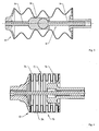
- Fig. 1 shows the schematic structure of the joint 10 according to the invention.
- the joint 10 consists of a first joint part 12, which is enclosed by a second joint part 14.
- a hydraulic clamping element 16 is arranged, with which the joint 10 with a tool 20 or a drive (not shown) can be connected.
- the tool 20 is the rotor of an eccentric screw pump.
- the hydraulic tensioning element 16 is a clamping bushing known from the art.
- the hydraulic tensioning element 16 is pushed onto a propeller shaft 30.
- the tool 20 or the drive are applied to the wall 17 of the clamping element 16.
- the wall 17 expands and is pressed against the tool inner wall 32. Due to the expansion of the wall 17, the hydraulic tensioning element 16 is releasably and non-positively connected to the propeller shaft 30 and the tool inner wall 32.
- Fig. 2 schematically shows the structure of a joint 10 with a profiled first hinge part 12.
- Fig. 3 shows schematically the construction of a joint 10 with a two-part first joint part 12 and additional joint 28.
- the first joint part 12 consists, in this embodiment, for receiving additional forces, from a first part 24 and a second part 26.
- the first part 24 and the second part 26 are connected to each other by an additional joint 28.
- Fig. 4 shows a hinge 10 in which the outer interstices 15 of the second joint part 14 are filled with an elastomer 34.
- This elastomer 34 is adapted to prevent particles that might penetrate into the outer spaces 15.
- the elastomer 34 used is subject to the influence of various pumped media, but since it does not fulfill any sealing or kinetic tasks, swelling or a chemical change of the elastomer at this point of the joint 10 is unproblematic and thus negligible.
- first joint part 12 is shown as a bending rod and the second joint part as a bellows.
- first joint part 12 is shown as a bending rod and the second joint part as a bellows.
Landscapes
- Engineering & Computer Science (AREA)
- General Engineering & Computer Science (AREA)
- Mechanical Engineering (AREA)
- Details And Applications Of Rotary Liquid Pumps (AREA)
- Rotary Pumps (AREA)
- Pivots And Pivotal Connections (AREA)
- Diaphragms And Bellows (AREA)
Description
- Die vorliegende Erfindung betrifft ein Gelenk, mit welchem Axialkräfte und Drehmomente in Verbindung mit exzentrischen Rotationsbewegungen von Pumpen übertragen bzw. aufgenommen werden können.
- Die schweizer Patentschrift
CH 446 913 - Die deutsche Patentanmeldung
DE 198 43 333 A1 offenbart eine winkelbewegliche Kraftübertragungsvorrichtung bestehend aus einem Gehäuse und einem darin schwenkbaren Kugelkopf, der durch einen ihn durchdringenden Bolzen drehfest mit dem Gehäuse verbunden ist. Die Bohrung des Kugelkopfes ist so erweitert, dass auf dem Bolzen ein bombierter Mitnehmer gleitend angeordnet werden kann, der bei Taumel, Exzenter- oder Winkelbewegungen zwischen angetriebenem Element und Antriebseinheit den Schwenkbewegungen des Kugelkopfes folgt und stets mit Teilflächen an der Innenfläche der Bohrung anliegt. Die Abstützung des Kugelkopfes bei Axialschüben erfolgt durch eine im Gehäuse schwimmend angeordnete Kalotte. In weiteren Ausführungen sind die seitliche Führung des Mitnehmers in der Bohrung, eine vereinfachte Form des Mitnehmers, die Abdichtung des Innenraums der Vorrichtung und die rückwärtige Abstützung des Kugelkopfes bei Axialzug beschrieben. - Die deutsche Patentschrift
DE 103 35 966 B3 offenbart eine Exzenterschneckenpumpe mit einem Antrieb, der über eine Zwischenwelle mit einer Rotor/Statorkombination in Verbindung steht. Die Zwischenwelle ist ohne Zwischenschaltung von Gelenken sowohl mit dem Rotor als auch mit dem Antrieb oder einer Antriebswelle verbunden. Der Querschnitt der Zwischenwelle ist mehrmals reduziert, wobei die Zwischenwelle mindestens zwei versetzt zueinander angeordnete, senkrecht zur Längsachse der Zwischenwelle verlaufende Stege aufweist. Zwischen den Stegen ist eine Zwischenwand angeordnet. - Die deutsche Patentanmeldung
DE 10 2004 043 183 A1 offenbart ein Drehgelenk, beispielsweise zum Antrieb eines schneckenförmigen Rotors einer Exzenterschneckenpumpe. Das Gelenk weist ein gekrümmtes schlauchförmiges Verbindungselement auf. Dieses Verbindungselement besteht aus einem Elastomer und nimmt eine, die Antriebskraft übertragende, ebenfalls schlauchförmige, Einlage auf. - Der Erfindung liegt die Aufgabe zugrunde, ein Gelenk zu schaffen, mit welchem Drehmomente und Axialkräfte einer Antriebswelle auf eine Maschine und/oder eine Exzenterschneckenpumpe ökonomisch, betriebssicher und unkompliziert übertragbar sind.
- Die obige Aufgabe wird durch ein Gelenk gelöst, das die Merkmale des Anspruchs 1 umfasst. Weitere vorteilhafte Merkmale sind den Unteransprüchen zu entnehmen.
- Eine weitere Aufgabe der Erfindung ist es, ein Verfahren bereit zu stellen, mit dem Drehmomente und Axialkräfte einer Antriebswelle auf eine Maschine und/oder eine Exzenterschneckenpumpe ökonomisch, betriebssicher und unkompliziert übertragen werden können.
- Diese Aufgabe wird durch ein Verfahren gelöst, welches die Merkmale des Anspruches 11 umfasst.
- Die Erfindung offenbart ein Gelenk zur Übertragung von Drehmomenten und Axialkräften in Verbindung mit einer exzentrischen Rotationsbewegung. In einer bevorzugten Ausführungsform wird das erfindungsgemäße Gelenk in einer Exzenterschneckenpumpe zur Verbindung des Antriebes mit dem Pumpenrotor eingesetzt. Das Gelenk verbindet eine Kuppelstange und ein Werkzeug und/oder einen Antrieb miteinander. Bei der Verwendung des Gelenks in einer Exzenterschneckenpumpe ist das Werkzeug der Rotor der Exzenterschneckenpumpe. Weiterhin ist das Gelenk mit mindestens einer Ummantelung versehen. Die Kräfteübertragung erfolgt im Wesentlichen ohne Verwendung von Elastomeren und die Axialkräfte, die auf das Gelenk wirken, sind von einem ersten Gelenkteil und die Drehmomente von einem zweiten Gelenkteil übertrag- und/oder aufnehmbar, wobei im ersten Gelenkteil nutförmige Einschnürungen eingebracht sind und das zweite Gelenk die Ummantelung bildet.
- In der bevorzugten Ausführungsform ist das erste Gelenkteil ein Biegestab, ein Bolzen oder ein zusätzliches Gelenk, wobei das erste Gelenkteil im Zentrum des zweiten Gelenkteils angeordnet ist. Das erste Gelenkteil ist aus einem biegesteifen Material hergestellt und kann verschiedene geometrische Gestaltungsformen aufweisen. Weiterhin ist das Material, aus dem das erste Gelenkteil hergestellt ist, elastisch bzw. frei drehbar. Somit ist es idealerweise nicht möglich, mit dem ersten Gelenkteil Drehmoment zu übertragen. Weiterhin kann das erste Gelenkteil aus einem ersten Teil und einem zweiten Teil aufgebaut sein. Der erste Teil und der zweite Teil sind über ein weiteres Gelenk miteinander verbunden. In einer bevorzugten Ausführungsform ist das zusätzliche Gelenk ein Kugelgelenk.
- Das zweite Gelenkteil ist eine verwindungssteife Ummantelung für das Gelenk, die vorzugsweise als Balg oder als Membrane ausgestaltet ist. Das zweite Gelenkteil ist aus einem Metall, einem Kunststoff oder einem Verbundwerkstoff hergestellt. Das Material, aus dem die Ummantelung hergestellt wird, ist so zu wählen, dass es trotz seiner Verwindungssteifheit biegeelastisch ist. Bei der bevorzugten Ausführungsform ist es mit der Ummantelung nicht möglich Axialkräfte zu übertragen. In einer weiteren Ausführungsform ist das zweite Gelenkteil mehrteilig ausgestattet. Bei der mehrlagigen Ausgestaltung können Gelenkteile aus gleichen oder unterschiedlichen Werkstoffen Verwendung finden.
- Das Werkzeug und/oder der Antrieb sind durch ein hydraulisches Spannelement mit dem Gelenk verbunden. Für den Fachmann ist klar, dass anstelle der hydraulischen Spannelemente die verschiedensten Elemente verwendet werden können, die geeignet sind, das Gelenk zum Beispiel mit einem Werkzeug zu verbinden. Das hydraulische Spannelement stellt eine lösbare, kraftschlüssige Verbindung dar.
- Weiterhin ist ein Verfahren zur Verwendung eines erfindungsgemäßen Gelenkes offenbart, wobei das erste Gelenkteil in einem zweiten Gelenkteil geführt wird. Mit dem ersten Gelenkteil werden Axialkräfte aufgenommen und/oder übertragen, wobei im ersten Gelenkteil nutförmige Einschnürungen in bestimmten Abständen zueinander eingebracht sind. Dadurch, dass der zweite Gelenkteil aus einem verwindungssteifen Material hergestellt ist, ist es möglich, mit diesem die Übertragung von Drehmomenten zu realisieren. Durch die Ummantelung der beweglichen Teile ist es möglich, das erfindungsgemäße Gelenk mit oder ohne Schmiermittel zu verwenden. Dies bringt zum Beispiel erhebliche Vorteile beim Einsatz einer Exzenterschneckenpumpe im Bereich der Lebensmittelförderung, da beim Einsatz des erfindungsgemäßen Gelenks kein Produkt mehr mit Schmiermitteln kontaminiert werden kann.
- Durch den Einsatz des hydraulischen Spannelements sind das Werkzeug und/oder der Antrieb über eine gewindelose Verbindung mit dem Gelenk verbunden. Der erste Gelenkteil wird aus verschiedenen Materialien hergestellt. Weiterhin ist es möglich, dass der erste Gelenkteil aus einem ersten Teil und einem zweiten Teil zusammengesetzt wird und das der erste Teil und der zweite Teil durch ein weiteres Gelenk verbunden werden.
- In dem erfindungsgemäßen Gelenk werden keine Elastomere verwendet. Hierdurch entstehen weniger Probleme mit der Beständigkeit gegenüber aggressiven Medien. Ein weiterer großer Vorteil liegt darin, dass Medien in einem wesentlich größeren Temperaturbereich gehändelt werden. Weiterhin besteht die Möglichkeit, dass die äußeren Zwischenräume des zweiten Gelenkteils gegen das Eindringen von Fremdkörpern geschützt sind. Dieser Schutz kann aus einer Ummantelung bestehen, die um den zweiten Gelenkteil angeordnet wird. Weiterhin ist es möglich, dass die äußeren Zwischenräume des zweiten Gelenkteils mit einem Elastomer ausgeschäumt werden. Durch dieses Elastomer und/oder durch die Ummantelung wird verhindert, dass Kleinteile in die Nähe des Gelenkes und/oder in die äußeren Zwischenräume des zweiten Gelenkteiles gelangen können und dieses beschädigen.
- Im Folgenden sollen Ausführungsbeispiele die Erfindung und ihre Vorteile anhand der beigefügten Figuren näher erläutern. Die Größenverhältnisse der einzelnen Elemente zueinander in den Figuren entsprechen nicht immer den realen Größenverhältnissen, da einige Formen vereinfacht und andere Formen zur besseren Veranschaulichung vergrößert im Verhältnis zu anderen Elementen dargestellt sind.
-
Fig. 1 zeigt den schematischen Aufbau des erfindungsgemäßen Gelenks. -
Fig. 2 zeigt schematisch den Aufbau eines Gelenks mit einem profilierten ersten Gelenkteil. -
Fig. 3 zeigt schematisch den Aufbau eines Gelenks mit einem zweiteiligen ersten Gelenkteil und zusätzlichem Gelenk. -
Fig. 4 zeigt ein Gelenk, bei dem die äußeren Zwischenräume des zweiten Gelenkteils mit einem Elastomer aufgefüllt sind. -
Fig. 1 zeigt den schematischen Aufbau des erfindungsgemäßen Gelenks 10. Das Gelenk 10 besteht aus einem ersten Gelenkteil 12, das von einem zweiten Gelenkteil 14 umschlossen ist. An der der Kuppelstange 18 gegenüberliegenden Seite ist ein hydraulisches Spannelement 16 angeordnet, mit welchem das Gelenk 10 mit einem Werkzeug 20 oder einem Antrieb (nicht dargestellt) verbunden werden kann. In derFigur 1 ist das Werkzeug 20 der Rotor einer Exzenterschneckenpumpe. - Bei dem hydraulischen Spannelement 16 handelt es sich um eine aus der Technik bekannte Spannbuchse. Das hydraulische Spannelement 16 wird auf eine Gelenkwelle 30 aufgeschoben. Das Werkzeug 20 oder der Antrieb werden auf die Wandung 17 des Spannelementes 16 aufgebracht. Durch das Drehen einer Einstellschraube (nicht dargestellt), expandiert die Wandung 17 und wird an die Werkzeuginnenwand 32 angepresst. Durch die Expansion der Wandung 17 ist das hydraulische Spannelement 16 lösbar und kraftschlüssig mit der Gelenkwelle 30 und der Werkzeuginnenwand 32 verbunden.
-
Fig. 2 zeigt schematisch den Aufbau eines Gelenks 10 mit einem profilierten ersten Gelenkteil 12. Durch diese Profilierung ist es möglich die Biegeeigenschaften beim Übergang der Vertikalauslenkung in die Horizontalauslenkung zu verbessern. Dieses verbesserte Verhalten kann auch durch eine nutförmige Einschnürung (nicht dargestellt) im ersten Gelenkteil 12 bewirkt werden. Durch das Einbringen einer zusätzlichen nutförmigen Einschnürung würde die Elastizität nochmals erhöht. Bei diesem ersten Gelenkteil 12 sind nutförmige Einschnürungen in bestimmten Abständen zueinander eingebracht, welche die Festigkeit des ersten Gelenkteils 12 nicht beeinflussen, aber eine Materialersparnis darstellen. Weiterhin werden durch die nutförmigen Einschnürungen in dem ersten Gelenkteil 12 die Rückstellkräfte verringert. Um den modifizierten ersten Gelenkteil 12 aufzunehmen, sind die Verbindung 19 zur Kuppelstange (nicht dargestellt) und die Gelenkwelle 30, im Vergleich zurFigur 1 , an die Erfordernisse angepasst worden. -
Fig. 3 zeigt schematisch den Aufbau eines Gelenks 10 mit einem zweiteiligen ersten Gelenkteil 12 und zusätzlichem Gelenk 28. Der erste Gelenkteil 12 besteht, in diesem Ausführungsbeispiel zur Aufnahme zusätzlicher Kräfte, aus einem ersten Teil 24 und einem zweiten Teil 26. Der erste Teil 24 und der zweite Teil 26 sind durch ein zusätzliches Gelenk 28 miteinander verbunden. -
Fig. 4 zeigt ein Gelenk 10, bei dem die äußeren Zwischenräume 15 des zweiten Gelenkteils 14 mit einem Elastomer 34 aufgefüllt sind. Dieses Elastomer 34 ist dazu geeignet, Partikel, die in die äußeren Zwischenräume 15 eindringen könnten, abzuhalten. Das eingesetzte Elastomer 34 ist zwar dem Einfluss verschiedener Fördermedien ausgesetzt, da es aber keine dichtenden oder bewegungstechnischen Aufgaben erfüllt, ist ein Quellen oder eine chemische Veränderung des Elastomers an dieser Stelle des Gelenks 10 unproblematisch und somit vernachlässigbar. - In den
Figuren 1 bis 4 ist der erste Gelenkteil 12 als Biegestab und der zweite Gelenkteil als Faltenbalg dargestellt. Für den Fachmann ergibt sich aus diesen Ausgestaltungsformen keine abschließende Begrenzung der Erfindung. Für die Aufnahme von Drehmomenten und/oder Axialkräften sind aus dem Stand der Technik viele Vorrichtungen und Verfahren hierzu bekannt. - Die Erfindung wurde unter Bezugnahme auf eine bevorzugte Ausführungsform beschrieben.
-
- 10
- Gelenk
- 12
- erster Gelenkteil
- 14
- zweiter Gelenkteil
- 15
- Zwischenräume
- 16
- hydraulisches Spannelement
- 17
- Wandung des Spannelements
- 18
- Kuppelstange
- 19
- Verbindung zur Kuppelstange
- 20
- Werkzeug
- 24
- erster Teil
- 26
- zweiter Teil
- 28
- weiteres Gelenk
- 30
- Gelenkwelle
- 32
- Werkzeuginnenwand
- 34
- Elastomer
Claims (16)
- Gelenk (10) zur Übertragung von Drehmomenten und Axialkräften in Verbindung mit einer exzentrischen Rotationsbewegung, wobei das Gelenk (10) eine Kuppelstange (18), ein Werkzeug (20) und/oder einen Antrieb verbindet und mit mindestens einer Ummantelung versehen ist, dadurch gekennzeichnet, dass die Kräfteübertragung im Wesentlichen ohne Verwendung von Elastomeren erfolgt und die Axialkräfte von einem ersten Gelenkteil (12) und die Drehmomente von einem zweiten Gelenkteil (14) übertragbar sind, wobei im ersten Gelenkteil (12) nutförmige Einschnürungen eingebracht sind und das zweite Gelenkteil (14) die Ummantelung bildet.
- Gelenk (10) nach Anspruch 1, dadurch gekennzeichnet, dass das erste Gelenkteil (12) ein Biegestab, ein Bolzen oder ein zusätzliches Gelenk ist und dass das erste Gelenkteil (12) im Zentrum des zweiten Gelenkteils (14) angeordnet ist.
- Gelenk (10) nach Anspruch 2, dadurch gekennzeichnet, dass das erste Gelenkteil (12) aus einem biegesteifen Material hergestellt ist.
- Gelenk (10) nach einem der Ansprüche 2 oder 3, dadurch gekennzeichnet, dass das erste Gelenkteil (12) verschiedene geometrische Gestaltungsformen aufweist.
- Gelenk (10) nach einem der Ansprüche 2 bis 4, dadurch gekennzeichnet, dass das erste Gelenkteil (12) aus einem ersten Teil (24) und einem zweiten Teil (26) aufgebaut ist.
- Gelenk (10) nach Anspruch 5, dadurch gekennzeichnet, dass der erste Teil (24) und der zweite Teil (26) des ersten Gelenkteils (12) über ein weiteres Gelenk (28) verbunden sind.
- Gelenk (10) nach Anspruch 1, dadurch gekennzeichnet, dass das zweite Gelenkteil (14) eine verwindungssteife Ummantelung für das Gelenk (10), vorzugsweise ein Balg oder eine Membrane ist, wobei das zweite Gelenkteil (14) auch mehrlagig herstellbar ist.
- Gelenk (10) nach Anspruch 7, dadurch gekennzeichnet, dass das zweite Gelenkteil (14) aus einem Metall, einem Kunststoff oder einem Verbundwerkstoff hergestellt ist.
- Gelenk nach einem der Ansprüche 7 oder 8, dadurch gekennzeichnet, dass die äußeren Zwischenräume (15) des zweiten Gelenkteils (14) gegen das Eindringen von Fremdkörpern geschützt sind.
- Gelenk nach Anspruch 9, dadurch gekennzeichnet, dass die äußeren Zwischenräume (15) des zweiten Gelenkteils (14) mit einem Elastomer (34) ausgefüllt sind.
- Gelenk (10) nach einem der Ansprüche 1 bis 10, dadurch gekennzeichnet, dass das Werkzeug (20) und/oder der Antrieb durch ein hydraulisches Spannelement (16) mit dem Gelenk (10) verbunden sind.
- Gelenk nach Anspruch 11, dadurch gekennzeichnet, dass das hydraulische Spannelement (16) eine lösbare, kraft- und formschlüssige Verbindung darstellt.
- Verfahren, bei dem ein Gelenke (10) gemäß einem der Ansprüche 1 bis 12 verwendet wird, dadurch gekennzeichnet, dass- das erste Gelenkteil (12) in einem zweiten Gelenkteil (14) geführt wird;- mit dem ersten Gelenkteil (12) Axialkräfte aufgenommen und/oder übertragen werden;- im ersten Gelenkteil (12) nutförmige Einschnürungen in bestimmten Abständen zueinander eingebracht sind;- der zweite Gelenkteil (14) aus einem verwindungssteifen Material hergestellt wird und dass mit dem zweiten Gelenkteil (14) Drehmomente übertragen werden und- in dem Gelenk (10) keine Schmiermittel eingesetzt werden und in dem keine Elastomere zur Kraftübertragung Verwendung finden.
- Verfahren nach Anspruch 13, dadurch gekennzeichnet, dass das Werkzeug (20) und/oder der Antrieb durch ein hydraulisches Spannelement (16) mit dem Gelenk (10) gewindelos verbunden werden.
- Verfahren nach einem der Ansprüche 13 oder 14, dadurch gekennzeichnet, dass das erste Gelenkteil (12) aus verschiedenen Materialien hergestellt wird.
- Verfahren nach einem der Ansprüche 13 bis 15, dadurch gekennzeichnet, dass der erste Gelenkteil (12) aus einem ersten Teil (24) und einem zweiten Teil (26) zusammengesetzt wird, und dass der erste Teil (24) und der zweite Teil (26) durch ein weiteres Gelenk (28) verbunden werden.
Applications Claiming Priority (2)
| Application Number | Priority Date | Filing Date | Title |
|---|---|---|---|
| DE102011014284A DE102011014284A1 (de) | 2011-03-17 | 2011-03-17 | Gelenk zur Übertragung von Drehmomenten und Axialkräften |
| PCT/DE2012/000270 WO2012122972A1 (de) | 2011-03-17 | 2012-03-13 | Gelenk zur übertragung von drehmomenten und axialkräften |
Publications (2)
| Publication Number | Publication Date |
|---|---|
| EP2686557A1 EP2686557A1 (de) | 2014-01-22 |
| EP2686557B1 true EP2686557B1 (de) | 2015-08-19 |
Family
ID=46052495
Family Applications (1)
| Application Number | Title | Priority Date | Filing Date |
|---|---|---|---|
| EP12720082.2A Active EP2686557B1 (de) | 2011-03-17 | 2012-03-13 | Gelenk zur übertragung von drehmomenten und axialkräften |
Country Status (11)
| Country | Link |
|---|---|
| US (1) | US20140016991A1 (de) |
| EP (1) | EP2686557B1 (de) |
| KR (1) | KR20140029405A (de) |
| CN (1) | CN103443461A (de) |
| AU (1) | AU2012228758A1 (de) |
| DE (1) | DE102011014284A1 (de) |
| MY (1) | MY164358A (de) |
| RU (1) | RU2573538C2 (de) |
| SG (1) | SG193507A1 (de) |
| WO (1) | WO2012122972A1 (de) |
| ZA (1) | ZA201306955B (de) |
Families Citing this family (6)
| Publication number | Priority date | Publication date | Assignee | Title |
|---|---|---|---|---|
| US9546694B2 (en) * | 2013-08-15 | 2017-01-17 | Goodrich Corporation | Flexible couplings for power transmission devices |
| DE102014112550B4 (de) * | 2014-09-01 | 2016-06-16 | Seepex Gmbh | Exzenterschneckenpumpe |
| DE102020114017A1 (de) * | 2020-05-26 | 2021-12-02 | Schaeffler Technologies AG & Co. KG | Ausgleichskupplung |
| US12152588B1 (en) | 2023-05-26 | 2024-11-26 | Grant Prideco, Inc. | Free-mold stator for a progressing cavity pump |
| DE102023117805A1 (de) | 2023-07-06 | 2025-01-09 | Netzsch Pumpen & Systeme Gmbh | Exzenterschneckenpumpe |
| FR3165475A1 (fr) * | 2024-08-12 | 2026-02-13 | Stellantis Auto Sas | Joint de transmission pour essieu suspendu de véhicule automobile |
Citations (1)
| Publication number | Priority date | Publication date | Assignee | Title |
|---|---|---|---|---|
| US20060237637A1 (en) * | 2005-04-25 | 2006-10-26 | Reinhard Beatty | Motor-encoder system having a flexible coupling |
Family Cites Families (18)
| Publication number | Priority date | Publication date | Assignee | Title |
|---|---|---|---|---|
| ES335006A1 (es) | 1965-12-31 | 1967-11-16 | Streicher Max | Dispositivos de proteccion para la union de accionamiento. |
| US3399549A (en) * | 1967-01-03 | 1968-09-03 | North American Rockwell | Backlash-free spline joint |
| GB1211987A (en) * | 1968-04-29 | 1970-11-11 | Stenberg Flygt Ab | A screw pump provided with a radially movable rotor coupling |
| US3621674A (en) * | 1969-09-26 | 1971-11-23 | Ford Motor Co | Reinforced bellows universal joint |
| DE1957120A1 (de) * | 1969-11-13 | 1971-05-19 | Langer Paul Gerhard | Rotierende axial foerdernde Verdraengerpumpe |
| FR2112824A5 (de) * | 1970-11-10 | 1972-06-23 | Glaenzer Spicer Sa | |
| DE2311985A1 (de) * | 1973-03-10 | 1974-09-12 | Netzsch Mohnopumpen Gmbh | Winkelbewegliche elastische kupplung |
| DE3000477A1 (de) * | 1980-01-08 | 1981-07-09 | Lorenz 7312 Kirchheim Baron | Wellen-kreuzgelenk, insbesondere fuer eine exzenter-schneckenpumpe |
| USRE33322E (en) * | 1982-12-27 | 1990-09-04 | Dana Corporation | Drive line slip joint assembly |
| CN87214931U (zh) * | 1987-11-05 | 1988-07-06 | 东煤公司煤田地质局哈尔滨科研所 | 螺旋钻具快装接头 |
| RU2021551C1 (ru) * | 1992-02-26 | 1994-10-15 | Алексей Андреевич Бутаков | Муфта |
| DE19843333A1 (de) | 1998-09-22 | 2000-06-15 | Armatec Fts Armaturen | Winkelbewegliche Kraftübertragungsvorrichtung |
| US6722991B2 (en) * | 2001-03-15 | 2004-04-20 | Visteon Global Technologies, Inc. | Venting system and method for a driveshaft |
| DE10335966B3 (de) | 2003-08-04 | 2004-08-26 | Netzsch-Mohnopumpen Gmbh | Exzenterschneckenpumpe |
| DE102004043183A1 (de) * | 2004-09-07 | 2006-04-13 | Netzsch-Mohnopumpen Gmbh | Drehgelenk |
| WO2006055610A2 (en) * | 2004-11-16 | 2006-05-26 | Seicon, Limited | Variable stiffness flexible joint |
| FI123048B (fi) * | 2005-12-14 | 2012-10-15 | Vaahto Oy | Kytkentälaitteisto |
| CN101603412A (zh) * | 2008-06-10 | 2009-12-16 | 王来朋 | 一种长螺旋钻杆快换接头 |
-
2011
- 2011-03-17 DE DE102011014284A patent/DE102011014284A1/de not_active Withdrawn
-
2012
- 2012-03-13 RU RU2013146163/11A patent/RU2573538C2/ru not_active IP Right Cessation
- 2012-03-13 MY MYPI2013003377A patent/MY164358A/en unknown
- 2012-03-13 AU AU2012228758A patent/AU2012228758A1/en not_active Abandoned
- 2012-03-13 SG SG2013069976A patent/SG193507A1/en unknown
- 2012-03-13 EP EP12720082.2A patent/EP2686557B1/de active Active
- 2012-03-13 WO PCT/DE2012/000270 patent/WO2012122972A1/de not_active Ceased
- 2012-03-13 KR KR1020137027003A patent/KR20140029405A/ko not_active Ceased
- 2012-03-13 CN CN2012800137944A patent/CN103443461A/zh active Pending
-
2013
- 2013-09-16 ZA ZA2013/06955A patent/ZA201306955B/en unknown
- 2013-09-17 US US14/029,163 patent/US20140016991A1/en not_active Abandoned
Patent Citations (1)
| Publication number | Priority date | Publication date | Assignee | Title |
|---|---|---|---|---|
| US20060237637A1 (en) * | 2005-04-25 | 2006-10-26 | Reinhard Beatty | Motor-encoder system having a flexible coupling |
Also Published As
| Publication number | Publication date |
|---|---|
| AU2012228758A1 (en) | 2013-09-26 |
| MY164358A (en) | 2017-12-15 |
| RU2013146163A (ru) | 2015-04-27 |
| RU2573538C2 (ru) | 2016-01-20 |
| US20140016991A1 (en) | 2014-01-16 |
| WO2012122972A1 (de) | 2012-09-20 |
| KR20140029405A (ko) | 2014-03-10 |
| SG193507A1 (en) | 2013-10-30 |
| DE102011014284A1 (de) | 2012-09-20 |
| ZA201306955B (en) | 2015-08-26 |
| EP2686557A1 (de) | 2014-01-22 |
| CN103443461A (zh) | 2013-12-11 |
Similar Documents
| Publication | Publication Date | Title |
|---|---|---|
| EP2406513B1 (de) | Schwingungsdämpfer für einen antriebsstrang | |
| DE4206974A1 (de) | Gelenkkupplung zur verwendung in einem bohrloch-bohrgeraet | |
| DE102012010869A1 (de) | Reduziereinrichtung eines elektrischen Servolenkungssystems | |
| EP2686557A1 (de) | Gelenk zur übertragung von drehmomenten und axialkräften | |
| EP3610154B1 (de) | Exzenterschneckenpumpe | |
| EP3253644B1 (de) | Vorrichtung zur einbringung eines hilfsdrehmoments in eine lenkwelle und elektro-mechanische hilfskraftlenkung | |
| DE2229418C3 (de) | Zahnkupplung | |
| DE102015002686B4 (de) | Einteilige Eingangswelle | |
| EP0845614B1 (de) | Polygonverbindung einer Nabe mit einer Welle | |
| DE102009057914A1 (de) | Schwingungsdämpfer für einen Antriebsstrang | |
| EP0175867B1 (de) | Kardanische Doppelkupplung | |
| EP2912328B1 (de) | Leichtbaugelenk für die übertragung von drehbewegungen | |
| EP2295800A2 (de) | Exzenterschneckenpumpe | |
| DE102011109895A1 (de) | Balgkupplung | |
| DE2139013C2 (de) | Exzenterschneckenpumpe | |
| DE4129913C2 (de) | ||
| EP4488523A1 (de) | Exzenterschneckenpumpe | |
| DE102007056371B4 (de) | Kugelverschiebegelenk mit geschrägten Kugellaufbahnen | |
| DE102009013082B4 (de) | Schwingungsdämpfer für einen Antriebsstrang | |
| DE8712742U1 (de) | Walzenmühle | |
| EP2288818A1 (de) | Tripodegelenk für kardanwelle eines kfz sowie kardanwelle | |
| DE3138931A1 (de) | Biegsame welle mit veraenderlichem kruemmungsradius | |
| DE4141325A1 (de) | Homokinetisches doppelkardangelenk elastisch zentriert | |
| WO2013020546A1 (de) | Schwingungsdämpfer für einen antriebsstrang | |
| WO2019174912A1 (de) | Manipulator mit gelenken und multifunktionsprofil hierfür |
Legal Events
| Date | Code | Title | Description |
|---|---|---|---|
| PUAI | Public reference made under article 153(3) epc to a published international application that has entered the european phase |
Free format text: ORIGINAL CODE: 0009012 |
|
| 17P | Request for examination filed |
Effective date: 20131017 |
|
| AK | Designated contracting states |
Kind code of ref document: A1 Designated state(s): AL AT BE BG CH CY CZ DE DK EE ES FI FR GB GR HR HU IE IS IT LI LT LU LV MC MK MT NL NO PL PT RO RS SE SI SK SM TR |
|
| DAX | Request for extension of the european patent (deleted) | ||
| 17Q | First examination report despatched |
Effective date: 20141104 |
|
| REG | Reference to a national code |
Ref country code: DE Ref legal event code: R079 Ref document number: 502012004221 Country of ref document: DE Free format text: PREVIOUS MAIN CLASS: F04C0015000000 Ipc: F16D0003840000 |
|
| GRAP | Despatch of communication of intention to grant a patent |
Free format text: ORIGINAL CODE: EPIDOSNIGR1 |
|
| RAP1 | Party data changed (applicant data changed or rights of an application transferred) |
Owner name: NETZSCH PUMPEN & SYSTEME GMBH |
|
| RIC1 | Information provided on ipc code assigned before grant |
Ipc: F16D 3/84 20060101AFI20150526BHEP |
|
| GRAS | Grant fee paid |
Free format text: ORIGINAL CODE: EPIDOSNIGR3 |
|
| INTG | Intention to grant announced |
Effective date: 20150618 |
|
| GRAA | (expected) grant |
Free format text: ORIGINAL CODE: 0009210 |
|
| AK | Designated contracting states |
Kind code of ref document: B1 Designated state(s): AL AT BE BG CH CY CZ DE DK EE ES FI FR GB GR HR HU IE IS IT LI LT LU LV MC MK MT NL NO PL PT RO RS SE SI SK SM TR |
|
| REG | Reference to a national code |
Ref country code: GB Ref legal event code: FG4D Free format text: NOT ENGLISH |
|
| REG | Reference to a national code |
Ref country code: CH Ref legal event code: EP |
|
| REG | Reference to a national code |
Ref country code: IE Ref legal event code: FG4D Free format text: LANGUAGE OF EP DOCUMENT: GERMAN |
|
| REG | Reference to a national code |
Ref country code: AT Ref legal event code: REF Ref document number: 744045 Country of ref document: AT Kind code of ref document: T Effective date: 20150915 |
|
| REG | Reference to a national code |
Ref country code: DE Ref legal event code: R096 Ref document number: 502012004221 Country of ref document: DE |
|
| REG | Reference to a national code |
Ref country code: LT Ref legal event code: MG4D |
|
| REG | Reference to a national code |
Ref country code: NL Ref legal event code: MP Effective date: 20150819 |
|
| PG25 | Lapsed in a contracting state [announced via postgrant information from national office to epo] |
Ref country code: LT Free format text: LAPSE BECAUSE OF FAILURE TO SUBMIT A TRANSLATION OF THE DESCRIPTION OR TO PAY THE FEE WITHIN THE PRESCRIBED TIME-LIMIT Effective date: 20150819 Ref country code: GR Free format text: LAPSE BECAUSE OF FAILURE TO SUBMIT A TRANSLATION OF THE DESCRIPTION OR TO PAY THE FEE WITHIN THE PRESCRIBED TIME-LIMIT Effective date: 20151120 Ref country code: LV Free format text: LAPSE BECAUSE OF FAILURE TO SUBMIT A TRANSLATION OF THE DESCRIPTION OR TO PAY THE FEE WITHIN THE PRESCRIBED TIME-LIMIT Effective date: 20150819 Ref country code: FI Free format text: LAPSE BECAUSE OF FAILURE TO SUBMIT A TRANSLATION OF THE DESCRIPTION OR TO PAY THE FEE WITHIN THE PRESCRIBED TIME-LIMIT Effective date: 20150819 Ref country code: NO Free format text: LAPSE BECAUSE OF FAILURE TO SUBMIT A TRANSLATION OF THE DESCRIPTION OR TO PAY THE FEE WITHIN THE PRESCRIBED TIME-LIMIT Effective date: 20151119 |
|
| PG25 | Lapsed in a contracting state [announced via postgrant information from national office to epo] |
Ref country code: PT Free format text: LAPSE BECAUSE OF FAILURE TO SUBMIT A TRANSLATION OF THE DESCRIPTION OR TO PAY THE FEE WITHIN THE PRESCRIBED TIME-LIMIT Effective date: 20151221 Ref country code: SE Free format text: LAPSE BECAUSE OF FAILURE TO SUBMIT A TRANSLATION OF THE DESCRIPTION OR TO PAY THE FEE WITHIN THE PRESCRIBED TIME-LIMIT Effective date: 20150819 Ref country code: ES Free format text: LAPSE BECAUSE OF FAILURE TO SUBMIT A TRANSLATION OF THE DESCRIPTION OR TO PAY THE FEE WITHIN THE PRESCRIBED TIME-LIMIT Effective date: 20150819 Ref country code: PL Free format text: LAPSE BECAUSE OF FAILURE TO SUBMIT A TRANSLATION OF THE DESCRIPTION OR TO PAY THE FEE WITHIN THE PRESCRIBED TIME-LIMIT Effective date: 20150819 Ref country code: RS Free format text: LAPSE BECAUSE OF FAILURE TO SUBMIT A TRANSLATION OF THE DESCRIPTION OR TO PAY THE FEE WITHIN THE PRESCRIBED TIME-LIMIT Effective date: 20150819 Ref country code: IS Free format text: LAPSE BECAUSE OF FAILURE TO SUBMIT A TRANSLATION OF THE DESCRIPTION OR TO PAY THE FEE WITHIN THE PRESCRIBED TIME-LIMIT Effective date: 20151219 |
|
| PG25 | Lapsed in a contracting state [announced via postgrant information from national office to epo] |
Ref country code: NL Free format text: LAPSE BECAUSE OF FAILURE TO SUBMIT A TRANSLATION OF THE DESCRIPTION OR TO PAY THE FEE WITHIN THE PRESCRIBED TIME-LIMIT Effective date: 20150819 |
|
| PG25 | Lapsed in a contracting state [announced via postgrant information from national office to epo] |
Ref country code: EE Free format text: LAPSE BECAUSE OF FAILURE TO SUBMIT A TRANSLATION OF THE DESCRIPTION OR TO PAY THE FEE WITHIN THE PRESCRIBED TIME-LIMIT Effective date: 20150819 Ref country code: DK Free format text: LAPSE BECAUSE OF FAILURE TO SUBMIT A TRANSLATION OF THE DESCRIPTION OR TO PAY THE FEE WITHIN THE PRESCRIBED TIME-LIMIT Effective date: 20150819 Ref country code: CZ Free format text: LAPSE BECAUSE OF FAILURE TO SUBMIT A TRANSLATION OF THE DESCRIPTION OR TO PAY THE FEE WITHIN THE PRESCRIBED TIME-LIMIT Effective date: 20150819 Ref country code: IT Free format text: LAPSE BECAUSE OF FAILURE TO SUBMIT A TRANSLATION OF THE DESCRIPTION OR TO PAY THE FEE WITHIN THE PRESCRIBED TIME-LIMIT Effective date: 20150819 Ref country code: SK Free format text: LAPSE BECAUSE OF FAILURE TO SUBMIT A TRANSLATION OF THE DESCRIPTION OR TO PAY THE FEE WITHIN THE PRESCRIBED TIME-LIMIT Effective date: 20150819 |
|
| REG | Reference to a national code |
Ref country code: DE Ref legal event code: R097 Ref document number: 502012004221 Country of ref document: DE |
|
| PG25 | Lapsed in a contracting state [announced via postgrant information from national office to epo] |
Ref country code: RO Free format text: LAPSE BECAUSE OF FAILURE TO SUBMIT A TRANSLATION OF THE DESCRIPTION OR TO PAY THE FEE WITHIN THE PRESCRIBED TIME-LIMIT Effective date: 20150819 |
|
| PLBE | No opposition filed within time limit |
Free format text: ORIGINAL CODE: 0009261 |
|
| STAA | Information on the status of an ep patent application or granted ep patent |
Free format text: STATUS: NO OPPOSITION FILED WITHIN TIME LIMIT |
|
| 26N | No opposition filed |
Effective date: 20160520 |
|
| PG25 | Lapsed in a contracting state [announced via postgrant information from national office to epo] |
Ref country code: BE Free format text: LAPSE BECAUSE OF NON-PAYMENT OF DUE FEES Effective date: 20160331 Ref country code: SI Free format text: LAPSE BECAUSE OF FAILURE TO SUBMIT A TRANSLATION OF THE DESCRIPTION OR TO PAY THE FEE WITHIN THE PRESCRIBED TIME-LIMIT Effective date: 20150819 |
|
| PG25 | Lapsed in a contracting state [announced via postgrant information from national office to epo] |
Ref country code: LU Free format text: LAPSE BECAUSE OF FAILURE TO SUBMIT A TRANSLATION OF THE DESCRIPTION OR TO PAY THE FEE WITHIN THE PRESCRIBED TIME-LIMIT Effective date: 20160313 Ref country code: MC Free format text: LAPSE BECAUSE OF FAILURE TO SUBMIT A TRANSLATION OF THE DESCRIPTION OR TO PAY THE FEE WITHIN THE PRESCRIBED TIME-LIMIT Effective date: 20150819 |
|
| REG | Reference to a national code |
Ref country code: CH Ref legal event code: PL |
|
| GBPC | Gb: european patent ceased through non-payment of renewal fee |
Effective date: 20160313 |
|
| REG | Reference to a national code |
Ref country code: IE Ref legal event code: MM4A |
|
| REG | Reference to a national code |
Ref country code: FR Ref legal event code: ST Effective date: 20161130 |
|
| PG25 | Lapsed in a contracting state [announced via postgrant information from national office to epo] |
Ref country code: CH Free format text: LAPSE BECAUSE OF NON-PAYMENT OF DUE FEES Effective date: 20160331 Ref country code: IE Free format text: LAPSE BECAUSE OF NON-PAYMENT OF DUE FEES Effective date: 20160313 Ref country code: GB Free format text: LAPSE BECAUSE OF NON-PAYMENT OF DUE FEES Effective date: 20160313 Ref country code: FR Free format text: LAPSE BECAUSE OF NON-PAYMENT OF DUE FEES Effective date: 20160331 Ref country code: LI Free format text: LAPSE BECAUSE OF NON-PAYMENT OF DUE FEES Effective date: 20160331 |
|
| PG25 | Lapsed in a contracting state [announced via postgrant information from national office to epo] |
Ref country code: MT Free format text: LAPSE BECAUSE OF FAILURE TO SUBMIT A TRANSLATION OF THE DESCRIPTION OR TO PAY THE FEE WITHIN THE PRESCRIBED TIME-LIMIT Effective date: 20150819 |
|
| REG | Reference to a national code |
Ref country code: AT Ref legal event code: MM01 Ref document number: 744045 Country of ref document: AT Kind code of ref document: T Effective date: 20170313 |
|
| PG25 | Lapsed in a contracting state [announced via postgrant information from national office to epo] |
Ref country code: HU Free format text: LAPSE BECAUSE OF FAILURE TO SUBMIT A TRANSLATION OF THE DESCRIPTION OR TO PAY THE FEE WITHIN THE PRESCRIBED TIME-LIMIT; INVALID AB INITIO Effective date: 20120313 Ref country code: CY Free format text: LAPSE BECAUSE OF FAILURE TO SUBMIT A TRANSLATION OF THE DESCRIPTION OR TO PAY THE FEE WITHIN THE PRESCRIBED TIME-LIMIT Effective date: 20150819 Ref country code: SM Free format text: LAPSE BECAUSE OF FAILURE TO SUBMIT A TRANSLATION OF THE DESCRIPTION OR TO PAY THE FEE WITHIN THE PRESCRIBED TIME-LIMIT Effective date: 20150819 |
|
| PG25 | Lapsed in a contracting state [announced via postgrant information from national office to epo] |
Ref country code: MK Free format text: LAPSE BECAUSE OF FAILURE TO SUBMIT A TRANSLATION OF THE DESCRIPTION OR TO PAY THE FEE WITHIN THE PRESCRIBED TIME-LIMIT Effective date: 20150819 Ref country code: TR Free format text: LAPSE BECAUSE OF FAILURE TO SUBMIT A TRANSLATION OF THE DESCRIPTION OR TO PAY THE FEE WITHIN THE PRESCRIBED TIME-LIMIT Effective date: 20150819 Ref country code: HR Free format text: LAPSE BECAUSE OF FAILURE TO SUBMIT A TRANSLATION OF THE DESCRIPTION OR TO PAY THE FEE WITHIN THE PRESCRIBED TIME-LIMIT Effective date: 20150819 |
|
| PG25 | Lapsed in a contracting state [announced via postgrant information from national office to epo] |
Ref country code: BG Free format text: LAPSE BECAUSE OF FAILURE TO SUBMIT A TRANSLATION OF THE DESCRIPTION OR TO PAY THE FEE WITHIN THE PRESCRIBED TIME-LIMIT Effective date: 20150819 |
|
| PG25 | Lapsed in a contracting state [announced via postgrant information from national office to epo] |
Ref country code: AT Free format text: LAPSE BECAUSE OF NON-PAYMENT OF DUE FEES Effective date: 20170313 |
|
| PG25 | Lapsed in a contracting state [announced via postgrant information from national office to epo] |
Ref country code: AL Free format text: LAPSE BECAUSE OF FAILURE TO SUBMIT A TRANSLATION OF THE DESCRIPTION OR TO PAY THE FEE WITHIN THE PRESCRIBED TIME-LIMIT Effective date: 20150819 |
|
| PGFP | Annual fee paid to national office [announced via postgrant information from national office to epo] |
Ref country code: DE Payment date: 20250331 Year of fee payment: 14 |