EP2686529B1 - Ensemble coudé de post-traitement des gaz d'echappement d'un moteur a combustion, groupe motopropulseur et vehicule associés - Google Patents
Ensemble coudé de post-traitement des gaz d'echappement d'un moteur a combustion, groupe motopropulseur et vehicule associés Download PDFInfo
- Publication number
- EP2686529B1 EP2686529B1 EP12712325.5A EP12712325A EP2686529B1 EP 2686529 B1 EP2686529 B1 EP 2686529B1 EP 12712325 A EP12712325 A EP 12712325A EP 2686529 B1 EP2686529 B1 EP 2686529B1
- Authority
- EP
- European Patent Office
- Prior art keywords
- catalyst
- branch
- nitrogen oxides
- catalytic reduction
- selective catalytic
- Prior art date
- Legal status (The legal status is an assumption and is not a legal conclusion. Google has not performed a legal analysis and makes no representation as to the accuracy of the status listed.)
- Active
Links
- MWUXSHHQAYIFBG-UHFFFAOYSA-N nitrogen oxide Inorganic materials O=[N] MWUXSHHQAYIFBG-UHFFFAOYSA-N 0.000 claims description 99
- 239000003054 catalyst Substances 0.000 claims description 50
- 239000003638 chemical reducing agent Substances 0.000 claims description 36
- 239000007789 gas Substances 0.000 claims description 33
- 238000007254 oxidation reaction Methods 0.000 claims description 33
- 230000003647 oxidation Effects 0.000 claims description 27
- 238000010531 catalytic reduction reaction Methods 0.000 claims description 22
- 239000002245 particle Substances 0.000 claims description 20
- 239000002243 precursor Substances 0.000 claims description 12
- 238000002485 combustion reaction Methods 0.000 claims description 11
- 239000000654 additive Substances 0.000 claims description 6
- 230000000996 additive effect Effects 0.000 claims description 6
- 238000006243 chemical reaction Methods 0.000 claims description 6
- 239000004071 soot Substances 0.000 claims description 6
- 238000009434 installation Methods 0.000 description 12
- IJGRMHOSHXDMSA-UHFFFAOYSA-N Atomic nitrogen Chemical compound N#N IJGRMHOSHXDMSA-UHFFFAOYSA-N 0.000 description 7
- 229910002091 carbon monoxide Inorganic materials 0.000 description 6
- 229930195733 hydrocarbon Natural products 0.000 description 6
- 150000002430 hydrocarbons Chemical class 0.000 description 6
- UGFAIRIUMAVXCW-UHFFFAOYSA-N Carbon monoxide Chemical compound [O+]#[C-] UGFAIRIUMAVXCW-UHFFFAOYSA-N 0.000 description 5
- 239000003344 environmental pollutant Substances 0.000 description 4
- 239000000203 mixture Substances 0.000 description 4
- 231100000719 pollutant Toxicity 0.000 description 4
- 230000009467 reduction Effects 0.000 description 4
- 238000006722 reduction reaction Methods 0.000 description 4
- 230000008901 benefit Effects 0.000 description 3
- 238000006555 catalytic reaction Methods 0.000 description 3
- 238000005516 engineering process Methods 0.000 description 3
- 239000008240 homogeneous mixture Substances 0.000 description 3
- 238000005470 impregnation Methods 0.000 description 3
- 230000000977 initiatory effect Effects 0.000 description 3
- 230000001105 regulatory effect Effects 0.000 description 3
- QGZKDVFQNNGYKY-UHFFFAOYSA-N Ammonia Chemical compound N QGZKDVFQNNGYKY-UHFFFAOYSA-N 0.000 description 2
- XSQUKJJJFZCRTK-UHFFFAOYSA-N Urea Chemical compound NC(N)=O XSQUKJJJFZCRTK-UHFFFAOYSA-N 0.000 description 2
- 230000000712 assembly Effects 0.000 description 2
- 238000000429 assembly Methods 0.000 description 2
- 239000004202 carbamide Substances 0.000 description 2
- 230000003197 catalytic effect Effects 0.000 description 2
- 239000003795 chemical substances by application Substances 0.000 description 2
- 238000000354 decomposition reaction Methods 0.000 description 2
- 239000012530 fluid Substances 0.000 description 2
- 239000000758 substrate Substances 0.000 description 2
- 238000011144 upstream manufacturing Methods 0.000 description 2
- 229910021529 ammonia Inorganic materials 0.000 description 1
- 230000015556 catabolic process Effects 0.000 description 1
- 230000008859 change Effects 0.000 description 1
- 238000006731 degradation reaction Methods 0.000 description 1
- 230000001627 detrimental effect Effects 0.000 description 1
- 230000002349 favourable effect Effects 0.000 description 1
- 238000010438 heat treatment Methods 0.000 description 1
- 238000005457 optimization Methods 0.000 description 1
- 230000037452 priming Effects 0.000 description 1
- 230000001737 promoting effect Effects 0.000 description 1
- 230000008929 regeneration Effects 0.000 description 1
- 238000011069 regeneration method Methods 0.000 description 1
- 230000009466 transformation Effects 0.000 description 1
- 230000004584 weight gain Effects 0.000 description 1
- 235000019786 weight gain Nutrition 0.000 description 1
Images

Classifications
-
- F—MECHANICAL ENGINEERING; LIGHTING; HEATING; WEAPONS; BLASTING
- F01—MACHINES OR ENGINES IN GENERAL; ENGINE PLANTS IN GENERAL; STEAM ENGINES
- F01N—GAS-FLOW SILENCERS OR EXHAUST APPARATUS FOR MACHINES OR ENGINES IN GENERAL; GAS-FLOW SILENCERS OR EXHAUST APPARATUS FOR INTERNAL COMBUSTION ENGINES
- F01N3/00—Exhaust or silencing apparatus having means for purifying, rendering innocuous, or otherwise treating exhaust
- F01N3/02—Exhaust or silencing apparatus having means for purifying, rendering innocuous, or otherwise treating exhaust for cooling, or for removing solid constituents of, exhaust
- F01N3/021—Exhaust or silencing apparatus having means for purifying, rendering innocuous, or otherwise treating exhaust for cooling, or for removing solid constituents of, exhaust by means of filters
-
- C—CHEMISTRY; METALLURGY
- C04—CEMENTS; CONCRETE; ARTIFICIAL STONE; CERAMICS; REFRACTORIES
- C04B—LIME, MAGNESIA; SLAG; CEMENTS; COMPOSITIONS THEREOF, e.g. MORTARS, CONCRETE OR LIKE BUILDING MATERIALS; ARTIFICIAL STONE; CERAMICS; REFRACTORIES; TREATMENT OF NATURAL STONE
- C04B38/00—Porous mortars, concrete, artificial stone or ceramic ware; Preparation thereof
- C04B38/0006—Honeycomb structures
- C04B38/0009—Honeycomb structures characterised by features relating to the cell walls, e.g. wall thickness or distribution of pores in the walls
-
- F—MECHANICAL ENGINEERING; LIGHTING; HEATING; WEAPONS; BLASTING
- F01—MACHINES OR ENGINES IN GENERAL; ENGINE PLANTS IN GENERAL; STEAM ENGINES
- F01N—GAS-FLOW SILENCERS OR EXHAUST APPARATUS FOR MACHINES OR ENGINES IN GENERAL; GAS-FLOW SILENCERS OR EXHAUST APPARATUS FOR INTERNAL COMBUSTION ENGINES
- F01N13/00—Exhaust or silencing apparatus characterised by constructional features ; Exhaust or silencing apparatus, or parts thereof, having pertinent characteristics not provided for in, or of interest apart from, groups F01N1/00 - F01N5/00, F01N9/00, F01N11/00
- F01N13/009—Exhaust or silencing apparatus characterised by constructional features ; Exhaust or silencing apparatus, or parts thereof, having pertinent characteristics not provided for in, or of interest apart from, groups F01N1/00 - F01N5/00, F01N9/00, F01N11/00 having two or more separate purifying devices arranged in series
- F01N13/0097—Exhaust or silencing apparatus characterised by constructional features ; Exhaust or silencing apparatus, or parts thereof, having pertinent characteristics not provided for in, or of interest apart from, groups F01N1/00 - F01N5/00, F01N9/00, F01N11/00 having two or more separate purifying devices arranged in series the purifying devices are arranged in a single housing
-
- F—MECHANICAL ENGINEERING; LIGHTING; HEATING; WEAPONS; BLASTING
- F01—MACHINES OR ENGINES IN GENERAL; ENGINE PLANTS IN GENERAL; STEAM ENGINES
- F01N—GAS-FLOW SILENCERS OR EXHAUST APPARATUS FOR MACHINES OR ENGINES IN GENERAL; GAS-FLOW SILENCERS OR EXHAUST APPARATUS FOR INTERNAL COMBUSTION ENGINES
- F01N13/00—Exhaust or silencing apparatus characterised by constructional features ; Exhaust or silencing apparatus, or parts thereof, having pertinent characteristics not provided for in, or of interest apart from, groups F01N1/00 - F01N5/00, F01N9/00, F01N11/00
- F01N13/02—Exhaust or silencing apparatus characterised by constructional features ; Exhaust or silencing apparatus, or parts thereof, having pertinent characteristics not provided for in, or of interest apart from, groups F01N1/00 - F01N5/00, F01N9/00, F01N11/00 having two or more separate silencers in series
-
- F—MECHANICAL ENGINEERING; LIGHTING; HEATING; WEAPONS; BLASTING
- F01—MACHINES OR ENGINES IN GENERAL; ENGINE PLANTS IN GENERAL; STEAM ENGINES
- F01N—GAS-FLOW SILENCERS OR EXHAUST APPARATUS FOR MACHINES OR ENGINES IN GENERAL; GAS-FLOW SILENCERS OR EXHAUST APPARATUS FOR INTERNAL COMBUSTION ENGINES
- F01N3/00—Exhaust or silencing apparatus having means for purifying, rendering innocuous, or otherwise treating exhaust
- F01N3/02—Exhaust or silencing apparatus having means for purifying, rendering innocuous, or otherwise treating exhaust for cooling, or for removing solid constituents of, exhaust
- F01N3/021—Exhaust or silencing apparatus having means for purifying, rendering innocuous, or otherwise treating exhaust for cooling, or for removing solid constituents of, exhaust by means of filters
- F01N3/023—Exhaust or silencing apparatus having means for purifying, rendering innocuous, or otherwise treating exhaust for cooling, or for removing solid constituents of, exhaust by means of filters using means for regenerating the filters, e.g. by burning trapped particles
- F01N3/025—Exhaust or silencing apparatus having means for purifying, rendering innocuous, or otherwise treating exhaust for cooling, or for removing solid constituents of, exhaust by means of filters using means for regenerating the filters, e.g. by burning trapped particles using fuel burner or by adding fuel to exhaust
- F01N3/0253—Exhaust or silencing apparatus having means for purifying, rendering innocuous, or otherwise treating exhaust for cooling, or for removing solid constituents of, exhaust by means of filters using means for regenerating the filters, e.g. by burning trapped particles using fuel burner or by adding fuel to exhaust adding fuel to exhaust gases
-
- F—MECHANICAL ENGINEERING; LIGHTING; HEATING; WEAPONS; BLASTING
- F01—MACHINES OR ENGINES IN GENERAL; ENGINE PLANTS IN GENERAL; STEAM ENGINES
- F01N—GAS-FLOW SILENCERS OR EXHAUST APPARATUS FOR MACHINES OR ENGINES IN GENERAL; GAS-FLOW SILENCERS OR EXHAUST APPARATUS FOR INTERNAL COMBUSTION ENGINES
- F01N3/00—Exhaust or silencing apparatus having means for purifying, rendering innocuous, or otherwise treating exhaust
- F01N3/02—Exhaust or silencing apparatus having means for purifying, rendering innocuous, or otherwise treating exhaust for cooling, or for removing solid constituents of, exhaust
- F01N3/021—Exhaust or silencing apparatus having means for purifying, rendering innocuous, or otherwise treating exhaust for cooling, or for removing solid constituents of, exhaust by means of filters
- F01N3/033—Exhaust or silencing apparatus having means for purifying, rendering innocuous, or otherwise treating exhaust for cooling, or for removing solid constituents of, exhaust by means of filters in combination with other devices
- F01N3/035—Exhaust or silencing apparatus having means for purifying, rendering innocuous, or otherwise treating exhaust for cooling, or for removing solid constituents of, exhaust by means of filters in combination with other devices with catalytic reactors, e.g. catalysed diesel particulate filters
-
- F—MECHANICAL ENGINEERING; LIGHTING; HEATING; WEAPONS; BLASTING
- F01—MACHINES OR ENGINES IN GENERAL; ENGINE PLANTS IN GENERAL; STEAM ENGINES
- F01N—GAS-FLOW SILENCERS OR EXHAUST APPARATUS FOR MACHINES OR ENGINES IN GENERAL; GAS-FLOW SILENCERS OR EXHAUST APPARATUS FOR INTERNAL COMBUSTION ENGINES
- F01N3/00—Exhaust or silencing apparatus having means for purifying, rendering innocuous, or otherwise treating exhaust
- F01N3/08—Exhaust or silencing apparatus having means for purifying, rendering innocuous, or otherwise treating exhaust for rendering innocuous
- F01N3/10—Exhaust or silencing apparatus having means for purifying, rendering innocuous, or otherwise treating exhaust for rendering innocuous by thermal or catalytic conversion of noxious components of exhaust
- F01N3/103—Oxidation catalysts for HC and CO only
-
- F—MECHANICAL ENGINEERING; LIGHTING; HEATING; WEAPONS; BLASTING
- F01—MACHINES OR ENGINES IN GENERAL; ENGINE PLANTS IN GENERAL; STEAM ENGINES
- F01N—GAS-FLOW SILENCERS OR EXHAUST APPARATUS FOR MACHINES OR ENGINES IN GENERAL; GAS-FLOW SILENCERS OR EXHAUST APPARATUS FOR INTERNAL COMBUSTION ENGINES
- F01N3/00—Exhaust or silencing apparatus having means for purifying, rendering innocuous, or otherwise treating exhaust
- F01N3/08—Exhaust or silencing apparatus having means for purifying, rendering innocuous, or otherwise treating exhaust for rendering innocuous
- F01N3/10—Exhaust or silencing apparatus having means for purifying, rendering innocuous, or otherwise treating exhaust for rendering innocuous by thermal or catalytic conversion of noxious components of exhaust
- F01N3/105—General auxiliary catalysts, e.g. upstream or downstream of the main catalyst
- F01N3/106—Auxiliary oxidation catalysts
-
- F—MECHANICAL ENGINEERING; LIGHTING; HEATING; WEAPONS; BLASTING
- F01—MACHINES OR ENGINES IN GENERAL; ENGINE PLANTS IN GENERAL; STEAM ENGINES
- F01N—GAS-FLOW SILENCERS OR EXHAUST APPARATUS FOR MACHINES OR ENGINES IN GENERAL; GAS-FLOW SILENCERS OR EXHAUST APPARATUS FOR INTERNAL COMBUSTION ENGINES
- F01N3/00—Exhaust or silencing apparatus having means for purifying, rendering innocuous, or otherwise treating exhaust
- F01N3/08—Exhaust or silencing apparatus having means for purifying, rendering innocuous, or otherwise treating exhaust for rendering innocuous
- F01N3/10—Exhaust or silencing apparatus having means for purifying, rendering innocuous, or otherwise treating exhaust for rendering innocuous by thermal or catalytic conversion of noxious components of exhaust
- F01N3/18—Exhaust or silencing apparatus having means for purifying, rendering innocuous, or otherwise treating exhaust for rendering innocuous by thermal or catalytic conversion of noxious components of exhaust characterised by methods of operation; Control
- F01N3/20—Exhaust or silencing apparatus having means for purifying, rendering innocuous, or otherwise treating exhaust for rendering innocuous by thermal or catalytic conversion of noxious components of exhaust characterised by methods of operation; Control specially adapted for catalytic conversion ; Methods of operation or control of catalytic converters
- F01N3/2066—Selective catalytic reduction [SCR]
-
- F—MECHANICAL ENGINEERING; LIGHTING; HEATING; WEAPONS; BLASTING
- F01—MACHINES OR ENGINES IN GENERAL; ENGINE PLANTS IN GENERAL; STEAM ENGINES
- F01N—GAS-FLOW SILENCERS OR EXHAUST APPARATUS FOR MACHINES OR ENGINES IN GENERAL; GAS-FLOW SILENCERS OR EXHAUST APPARATUS FOR INTERNAL COMBUSTION ENGINES
- F01N3/00—Exhaust or silencing apparatus having means for purifying, rendering innocuous, or otherwise treating exhaust
- F01N3/08—Exhaust or silencing apparatus having means for purifying, rendering innocuous, or otherwise treating exhaust for rendering innocuous
- F01N3/10—Exhaust or silencing apparatus having means for purifying, rendering innocuous, or otherwise treating exhaust for rendering innocuous by thermal or catalytic conversion of noxious components of exhaust
- F01N3/24—Exhaust or silencing apparatus having means for purifying, rendering innocuous, or otherwise treating exhaust for rendering innocuous by thermal or catalytic conversion of noxious components of exhaust characterised by constructional aspects of converting apparatus
- F01N3/28—Construction of catalytic reactors
- F01N3/2803—Construction of catalytic reactors characterised by structure, by material or by manufacturing of catalyst support
- F01N3/2825—Ceramics
- F01N3/2828—Ceramic multi-channel monoliths, e.g. honeycombs
-
- F—MECHANICAL ENGINEERING; LIGHTING; HEATING; WEAPONS; BLASTING
- F01—MACHINES OR ENGINES IN GENERAL; ENGINE PLANTS IN GENERAL; STEAM ENGINES
- F01N—GAS-FLOW SILENCERS OR EXHAUST APPARATUS FOR MACHINES OR ENGINES IN GENERAL; GAS-FLOW SILENCERS OR EXHAUST APPARATUS FOR INTERNAL COMBUSTION ENGINES
- F01N2240/00—Combination or association of two or more different exhaust treating devices, or of at least one such device with an auxiliary device, not covered by indexing codes F01N2230/00 or F01N2250/00, one of the devices being
- F01N2240/20—Combination or association of two or more different exhaust treating devices, or of at least one such device with an auxiliary device, not covered by indexing codes F01N2230/00 or F01N2250/00, one of the devices being a flow director or deflector
-
- F—MECHANICAL ENGINEERING; LIGHTING; HEATING; WEAPONS; BLASTING
- F01—MACHINES OR ENGINES IN GENERAL; ENGINE PLANTS IN GENERAL; STEAM ENGINES
- F01N—GAS-FLOW SILENCERS OR EXHAUST APPARATUS FOR MACHINES OR ENGINES IN GENERAL; GAS-FLOW SILENCERS OR EXHAUST APPARATUS FOR INTERNAL COMBUSTION ENGINES
- F01N2330/00—Structure of catalyst support or particle filter
- F01N2330/06—Ceramic, e.g. monoliths
-
- F—MECHANICAL ENGINEERING; LIGHTING; HEATING; WEAPONS; BLASTING
- F01—MACHINES OR ENGINES IN GENERAL; ENGINE PLANTS IN GENERAL; STEAM ENGINES
- F01N—GAS-FLOW SILENCERS OR EXHAUST APPARATUS FOR MACHINES OR ENGINES IN GENERAL; GAS-FLOW SILENCERS OR EXHAUST APPARATUS FOR INTERNAL COMBUSTION ENGINES
- F01N2330/00—Structure of catalyst support or particle filter
- F01N2330/30—Honeycomb supports characterised by their structural details
- F01N2330/48—Honeycomb supports characterised by their structural details characterised by the number of flow passages, e.g. cell density
-
- F—MECHANICAL ENGINEERING; LIGHTING; HEATING; WEAPONS; BLASTING
- F01—MACHINES OR ENGINES IN GENERAL; ENGINE PLANTS IN GENERAL; STEAM ENGINES
- F01N—GAS-FLOW SILENCERS OR EXHAUST APPARATUS FOR MACHINES OR ENGINES IN GENERAL; GAS-FLOW SILENCERS OR EXHAUST APPARATUS FOR INTERNAL COMBUSTION ENGINES
- F01N2340/00—Dimensional characteristics of the exhaust system, e.g. length, diameter or volume of the apparatus; Spatial arrangements of exhaust apparatuses
- F01N2340/02—Dimensional characteristics of the exhaust system, e.g. length, diameter or volume of the apparatus; Spatial arrangements of exhaust apparatuses characterised by the distance of the apparatus to the engine, or the distance between two exhaust treating apparatuses
-
- F—MECHANICAL ENGINEERING; LIGHTING; HEATING; WEAPONS; BLASTING
- F01—MACHINES OR ENGINES IN GENERAL; ENGINE PLANTS IN GENERAL; STEAM ENGINES
- F01N—GAS-FLOW SILENCERS OR EXHAUST APPARATUS FOR MACHINES OR ENGINES IN GENERAL; GAS-FLOW SILENCERS OR EXHAUST APPARATUS FOR INTERNAL COMBUSTION ENGINES
- F01N2340/00—Dimensional characteristics of the exhaust system, e.g. length, diameter or volume of the apparatus; Spatial arrangements of exhaust apparatuses
- F01N2340/04—Dimensional characteristics of the exhaust system, e.g. length, diameter or volume of the apparatus; Spatial arrangements of exhaust apparatuses characterised by the arrangement of an exhaust pipe, manifold or apparatus in relation to vehicle frame or particular vehicle parts
-
- F—MECHANICAL ENGINEERING; LIGHTING; HEATING; WEAPONS; BLASTING
- F01—MACHINES OR ENGINES IN GENERAL; ENGINE PLANTS IN GENERAL; STEAM ENGINES
- F01N—GAS-FLOW SILENCERS OR EXHAUST APPARATUS FOR MACHINES OR ENGINES IN GENERAL; GAS-FLOW SILENCERS OR EXHAUST APPARATUS FOR INTERNAL COMBUSTION ENGINES
- F01N2470/00—Structure or shape of gas passages, pipes or tubes
- F01N2470/22—Inlet and outlet tubes being positioned on the same side of the apparatus
-
- F—MECHANICAL ENGINEERING; LIGHTING; HEATING; WEAPONS; BLASTING
- F01—MACHINES OR ENGINES IN GENERAL; ENGINE PLANTS IN GENERAL; STEAM ENGINES
- F01N—GAS-FLOW SILENCERS OR EXHAUST APPARATUS FOR MACHINES OR ENGINES IN GENERAL; GAS-FLOW SILENCERS OR EXHAUST APPARATUS FOR INTERNAL COMBUSTION ENGINES
- F01N2490/00—Structure, disposition or shape of gas-chambers
- F01N2490/02—Two or more expansion chambers in series connected by means of tubes
- F01N2490/06—Two or more expansion chambers in series connected by means of tubes the gases flowing longitudinally from inlet to outlet in opposite directions
-
- F—MECHANICAL ENGINEERING; LIGHTING; HEATING; WEAPONS; BLASTING
- F01—MACHINES OR ENGINES IN GENERAL; ENGINE PLANTS IN GENERAL; STEAM ENGINES
- F01N—GAS-FLOW SILENCERS OR EXHAUST APPARATUS FOR MACHINES OR ENGINES IN GENERAL; GAS-FLOW SILENCERS OR EXHAUST APPARATUS FOR INTERNAL COMBUSTION ENGINES
- F01N2570/00—Exhaust treating apparatus eliminating, absorbing or adsorbing specific elements or compounds
- F01N2570/14—Nitrogen oxides
-
- F—MECHANICAL ENGINEERING; LIGHTING; HEATING; WEAPONS; BLASTING
- F01—MACHINES OR ENGINES IN GENERAL; ENGINE PLANTS IN GENERAL; STEAM ENGINES
- F01N—GAS-FLOW SILENCERS OR EXHAUST APPARATUS FOR MACHINES OR ENGINES IN GENERAL; GAS-FLOW SILENCERS OR EXHAUST APPARATUS FOR INTERNAL COMBUSTION ENGINES
- F01N2610/00—Adding substances to exhaust gases
- F01N2610/02—Adding substances to exhaust gases the substance being ammonia or urea
-
- F—MECHANICAL ENGINEERING; LIGHTING; HEATING; WEAPONS; BLASTING
- F01—MACHINES OR ENGINES IN GENERAL; ENGINE PLANTS IN GENERAL; STEAM ENGINES
- F01N—GAS-FLOW SILENCERS OR EXHAUST APPARATUS FOR MACHINES OR ENGINES IN GENERAL; GAS-FLOW SILENCERS OR EXHAUST APPARATUS FOR INTERNAL COMBUSTION ENGINES
- F01N2610/00—Adding substances to exhaust gases
- F01N2610/14—Arrangements for the supply of substances, e.g. conduits
- F01N2610/1453—Sprayers or atomisers; Arrangement thereof in the exhaust apparatus
-
- Y—GENERAL TAGGING OF NEW TECHNOLOGICAL DEVELOPMENTS; GENERAL TAGGING OF CROSS-SECTIONAL TECHNOLOGIES SPANNING OVER SEVERAL SECTIONS OF THE IPC; TECHNICAL SUBJECTS COVERED BY FORMER USPC CROSS-REFERENCE ART COLLECTIONS [XRACs] AND DIGESTS
- Y02—TECHNOLOGIES OR APPLICATIONS FOR MITIGATION OR ADAPTATION AGAINST CLIMATE CHANGE
- Y02A—TECHNOLOGIES FOR ADAPTATION TO CLIMATE CHANGE
- Y02A50/00—TECHNOLOGIES FOR ADAPTATION TO CLIMATE CHANGE in human health protection, e.g. against extreme weather
- Y02A50/20—Air quality improvement or preservation, e.g. vehicle emission control or emission reduction by using catalytic converters
-
- Y—GENERAL TAGGING OF NEW TECHNOLOGICAL DEVELOPMENTS; GENERAL TAGGING OF CROSS-SECTIONAL TECHNOLOGIES SPANNING OVER SEVERAL SECTIONS OF THE IPC; TECHNICAL SUBJECTS COVERED BY FORMER USPC CROSS-REFERENCE ART COLLECTIONS [XRACs] AND DIGESTS
- Y02—TECHNOLOGIES OR APPLICATIONS FOR MITIGATION OR ADAPTATION AGAINST CLIMATE CHANGE
- Y02T—CLIMATE CHANGE MITIGATION TECHNOLOGIES RELATED TO TRANSPORTATION
- Y02T10/00—Road transport of goods or passengers
- Y02T10/10—Internal combustion engine [ICE] based vehicles
- Y02T10/12—Improving ICE efficiencies
Definitions
- the present invention claims the priorities of French applications 1152142 filed March 16, 2011 and 1,153,159 filed on April 12, 2011 .
- the invention relates to the field of means for treating pollutants from the exhaust gases of combustion engines.
- Pollutant emissions from combustion engines fitted to motor vehicles are regulated by increasingly stringent standards.
- the regulated pollutants are - depending on the combustion engine technology considered - carbon monoxide (CO), unburnt hydrocarbons (HC), nitrogen oxides (NOx), and particles.
- An oxidation catalyst allows the treatment of carbon monoxide, unburnt hydrocarbons, and under certain conditions nitrogen oxides; a particulate filter can be used to treat soot particles.
- post-treatment means for the exhaust gases.
- a specific post-treatment system can be introduced in the exhaust line of vehicles, especially vehicles fitted with diesel engines.
- SCR selective catalytic reduction technologies
- a reducing agent or a precursor of such a reducing agent
- exhaust gases may for example be a urea solution, the decomposition of which will make it possible to obtain ammonia which will serve as a reducing agent, but also a reducing agent or a precursor of such a reducing agent under gaseous form.
- a reducing agent to designate a reducing agent or a reducing agent precursor.
- the reducing agent generated makes it possible to reduce the nitrogen oxides by reaction in an SCR catalyst, that is to say a substrate carrying a catalytic impregnation capable of promoting the reduction of NOx by the reducing agent.
- Selective catalytic reduction technologies have the advantage of allowing a very high level of conversion of nitrogen oxides.
- SCR catalysis requires adding a catalytic substrate in the exhaust line, as well as a means of introducing the reducer into the exhaust gases, which can for example be a reducer injector.
- the SCR catalyst is placed under the vehicle body, far from the engine because the injected reducer needs a long journey in the exhaust line to decompose on the one hand, and sufficient free volumes to establish itself on the other hand. If the distance traveled by the reduction gear is not sufficient, the risk of fouling of the exhaust line is high.
- the SCR catalyst may not be active from the first seconds of operation of the vehicle, and then lets through a large amount of untreated nitrogen oxides.
- the reductor injector which requires reaching a certain temperature level to be operational (sufficient initiation of the decomposition of the urea precursor (adblue) or preheating of the reducer (gas) supply system) , suffers from this distance from the outlet of the exhaust manifold.
- the envelope described in this application is of relatively short length thanks to the use of many optimizations described in this patent application.
- the architecture thus proposed may in particular have certain drawbacks, depending on the application for which it is intended.
- it is particularly suitable for vertical installation in the engine under-hood space of a combustion engine whose outlet of the exhaust manifold is located on the front face, that is to say on the side from the front of the equipped vehicle (if it has a space under the engine hood in its front part, which is mainly the case in automotive applications).
- this architecture requires making a more or less complex connection with the outlet of a turbocharger, this connection being able to generate thermal losses that are all the greater the longer it has or the greater the area, as for example in the case of a connecting elbow.
- the aim is to solve these problems by adopting an optimized architecture.
- the elbow forms an angle of approximately 90 °, giving the assembly an "L" geometry.
- the values of angles between 90 ° and 120 ° may be particularly advantageous for ensuring easy installation of the invention in an engine under-hood space of a motor vehicle.
- the particle filter is of the type involving an additive lowering the oxidation temperature of the soot particles.
- additive has the advantage, thanks to its lower soot oxidation temperature compared to a filter without additive (called “catalyzed”), of being able to be installed downstream of an SCR catalyst without its functioning. is not penalized too much by the thermal losses linked to its distance from the motor outlet.
- the particulate filter and the SCR catalyst consist of a single treatment monolith, the lower temperature level of the filter during its regenerations allows less degradation of the SCR impregnation on the filter.
- the elbow forms or comprises the mixing means. This makes it possible to obtain a homogeneous mixture between the exhaust gases and the SCR reducer as soon as the second branch enters.
- the mixing means comprise a mixer in the second branch. This allows the use of efficient mixers, known in the state of the art.
- the catalyst for the selective catalytic reduction of nitrogen oxides and the particulate filter consist of a single exhaust gas treatment monolith. It is a compact and efficient solution to allow a complete treatment of exhaust gases, which also allows to increase the volume of maximum storage of the particle filter for the same volume allocation to the two functions of NOx reduction and particle reduction.
- the assembly further comprises a turbocharger, the outlet of which is connected directly to the first branch. It is the best configuration to avoid any heat loss between these elements.
- the first branch associated with the turbocharger, including the turbocharger, has a length of at most 600mm, and preferably of the order of 380mm.
- the second branch has a length of at most 600mm, and preferably of the order of 380mm.
- the second branch may include an outlet convergent, preferably flat and / or having a lateral outlet, which reduces its bulk along the axis of the second branch.
- the invention also relates to a powertrain comprising a combustion engine with several cylinders, the cylinders of which are arranged in line, and an assembly according to the invention, in which the first branch is disposed parallel to the alignment formed by the cylinders.
- the invention finally relates to a motor vehicle comprising a powertrain according to the invention.
- the engine has a transverse arrangement, relative to the vehicle, in the under-hood space.
- the engine has a longitudinal arrangement, relative to the vehicle, in the under-hood space.
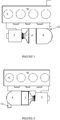
- the figure 1 presents an assembly according to a preferred embodiment of the invention, according to a schematic exterior view in 3 dimensions, according to a first angle of view.
- An assembly according to the invention comprises a first straight branch 1 and a second straight branch 2.
- the first and the second branch are connected by an elbow 8 forming a geometric angle between 60 ° and 120 °.
- the angle is substantially 90 °, giving the assembly an "L" shape.
- the first branch comprises an oxidation catalyst 4.
- the oxidation catalyst is mainly used for the treatment of unburnt hydrocarbons (HC) and carbon monoxide (CO) in the context of a diesel engine.
- the second branch comprises a catalyst for the selective catalytic reduction of nitrogen oxides, or SCR catalyst 5.
- the second branch also comprises a particle filter 6.
- the SCR catalyst 5 and the particle filter 6 can, depending on the variant of the invention considered, to be grouped into a single monolith known as “FAP / SCR” 7, namely a particle filter carrying an impregnation of selective catalytic reduction of nitrogen oxides.
- the figure 2 presents an embodiment having the only difference compared to that presented in figure 1 that it includes a single FAP / SCR 7 monolith.
- the particle filter 6, or the FAP / SCR 7, is preferably of a type involving an additive making it possible to lower the oxidation temperature of the soot. This characteristic allows the filter to regenerate at lower temperatures than a so-called “catalyzed” filter (designating a filter not using an additive for lowering the soot oxidation temperature).
- the first branch 1 is connected to the second branch by an elbow 8 forming a fluidic connection allowing the transport of the exhaust gases from the outlet of the first branch to the inlet of the second branch (the concepts of inlet and outlet understood throughout this document according to the direction of flow of the exhaust gases in the assembly according to the invention).
- This elbow 8 can also have an important role in the treatment of exhaust gases.
- SCR catalysis requires the introduction and mixing in the exhaust gas of a reducing agent (reducing agent or precursor of such an agent) by appropriate means such as a dedicated injector (not shown in the figures ).
- the mouth of an introduction means can advantageously be located in the fluid connection 8, preferably towards the inlet of said elbow in order to maximize the distance between the point of introduction of reducer and the SCR catalyst 5, such distance favoring the mixing of the reducer in the exhaust gases.
- the shape of the connector 8 can also be optimized so as to promote (or even completely realize) the homogeneous mixture of the reducer and the exhaust gases.
- the connection may in particular include an internal boss whose shape is optimized to generate turbulence ensuring mixing between the exhaust gases and the reducer.
- a bent configuration and in particular in an L configuration as proposed in the invention is moreover favorable to this phenomenon, due to the change of direction imposed on the flow of the exhaust gases by the elbow 8.
- the first branch also includes a turbocharger 3 connected directly to the envelope of the assembly, that is to say connected to the first branch 1. More specifically, the envelope is directly connected to the outlet of the turbine of the turbocharger 3, that is to say that a divergent forming the inlet of the envelope of the assembly is connected to the outlet of the turbine of the turbocharger 3.
- the turbocharger 3 is preferably oriented so that the outlet of its turbine or in the axis of the first branch 1.
- the first branch 1 associated with the turbocharger 3 included has a length of about 380mm. This length does not exceed 600mm, which makes it compatible with easy installation in an under-hood space of a motor vehicle, in particular in the width (for a transverse installation) or in the length (for a longitudinal installation) of the under-hood space.
- the second branch preferably has a length of the order of 380mm. Preferably, this length does not exceed 600mm, which makes it compatible with easy installation in an under-hood space of a motor vehicle, in particular in the height of the under-hood space.
- the first branch may (and will generally be) positioned substantially horizontally in the upper part in a space under the engine hood.
- the elbow 8 is as short as possible, thus forming a portion of toroid with a small internal radius, as close to a zero radius (portion of a torus says with a null necklace). It has at the inlet the same section as the casing at the outlet of the oxidation catalyst 4, and at the outlet the same section as the casing at the inlet of the second branch 2.
- the single casing of the set can have a section evolutionary, and for example pass from a circular section, to an elliptical or oval section, or vice versa.
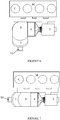
- An assembly according to the invention may include an added mixer 9, that is to say a device capable of generating turbulence and / or increasing the distance traveled by the exhaust gases so as to promote their homogeneous mixing with the reducing, or increasing their transport time before reaching the SCR catalyst, in order for example to allow the transformation into a reducing agent of a precursor of such an agent.
- the figure 3 thus presents a variant of the invention having a mixer attached in the second branch 2, followed by a FAP / SCR 7 monolith.
- the mixer 9 will preferably be placed in the second branch 2 upstream of the SCR catalyst 5 or of the FAP / SCR monolith 7.
- a mixer of the type known from the document FR2947003 it is preferable to use a mixer of the type known from the document FR2947003 .
- a simpler and less expensive mixer 9 can be used, for example a mixer 9 involving one or more mixing grids, or fins arranged in staggered rows.
- the second branch 2 also includes in the variant of the invention here shown an outlet convergent 10 in order to channel the exhaust gases treated by the assembly according to the invention.
- This convergent preferably has a lateral evacuation. This makes it possible to limit the length and to orient the flow of exhaust gases in an adequate manner.
- the first branch 1 and the second branch 2 have substantially equal lengths. This is made possible by the distribution of the functions proposed in the invention, namely, the supercharging and catalysis of HC and CO in the first branch 1, the treatment of NOx and particles in the second branch 2. From this distribution follows a major advantage in terms of ease of installation of an assembly according to the invention.
- round cylindrical monoliths in combination with round non-cylindrical monoliths.
- the figure 4 schematically shows a powertrain comprising a combustion engine M with four cylinders C in line.
- the invention is also applicable to engines of other types, in particular engines comprising from 2 to 6 cylinders.
- the assembly is seen from a point of view in the axis of the engine cylinders, which generally corresponds to a “top” view according to the conventional layout of such an engine in an under-hood space of a motor vehicle .
- the first branch 1 is located substantially parallel to the alignment of the cylinders, along an exhaust manifold E.
- the first branch can for example be arranged next to the manifold or under the manifold.
- the outlet of the convergent 10 is oriented towards the opposite face of the engine, so that the exhaust pipe passes under the engine.
- This variant is particularly intended for an application in which the powertrain is located transversely (orthogonally to the axis of the vehicle) in the under-hood space of a motor vehicle, with the pollution control assembly according to the invention positioned between the front of the vehicle and the engine.
- the figure 5 shows schematically from the same point of view a powertrain particularly intended to be installed transversely in the under-hood space of a motor vehicle, with the pollution control assembly according to the invention positioned between the engine and the bulkhead separating the space under the bonnet of the vehicle cabin.
- the figure 6 shows schematically from the same point of view a powertrain comprising an assembly according to the invention, the second branch 2 having an inclination with respect to the axis of the engine cylinders.
- This allows a partial installation of the assembly, always in the space under the engine hood, in the start of a tunnel (tunnel allowing the underfloor routing of the vehicle exhaust line.
- This oblique arrangement of the second branch also reduces the vertical size (along the axis of the engine cylinders) of the assembly, thus allowing the installation under the pollution control assembly of elements such as a motor cradle or a steering rack.
- the figure 7 shows schematically from the same point of view a powertrain comprising an assembly according to the invention, the outlet of the convergent 10 being directed along the alignment of the cylinders.
- This variant is particularly intended for an application in which the powertrain is located longitudinally (in the axis of the vehicle).
- the elbow also has an angle slightly greater than 90 °, which reduces the vertical size of the assembly.
- the invention thus developed, by allowing a distribution along two axes of the pollution control elements, promotes the establishment of a complete assembly for treating the exhaust gases of a combustion engine in a constrained environment where the assembly cannot be established along a single axis.
- the first branch comprises a turbocharger
- positioning the oxidation catalyst as close as possible to the outlet of the turbocharger makes it possible to limit the heat losses and to limit the thermal inertias opposing the rapid heating of the oxidation catalyst by the exhaust gas (significant thermal inertia is detrimental to the priming of the catalyst, especially in the context of standardized approval cycles).
- Positioning the oxidation catalyst directly at the outlet in line with the outlet of the turbocharger is the best architecture to allow rapid initiation of the oxidation catalyst, and therefore allows its size to be limited. In addition the losses of load between the turbine and the catalyst are limited.
- positioning as close as possible to the outlet of the turbine from the SCR catalyst promotes its rapid rise in temperature, and therefore its initiation.
- An elbow of short length and having a low thermal inertia makes it possible to optimize this rise in temperature.
- An architecture according to the invention therefore allows a virtuous circle as regards the dimensioning of the exhaust gas treatment monoliths, which makes it all the more easier to set up in a constrained environment and reduces the cost thereof.
- An architecture according to the invention with a first and a second branch and a bend between these branches further promotes the mixing of an SCR reducer introduced upstream of the second branch, for example in the bend.
- the shape of the elbow can be optimized to maximize the mixing of the reducer in the exhaust gases.
- an assembly according to the invention in an engine under-hood space of a motor vehicle offers a potential for significant weight gain compared with known architectures, in particular by allowing the removal of any post-installation device.
- under body treatment as well as any caulking device (heat shields, etc.) generally placed under the vehicle floor to minimize heat losses before entering the gas treatment means installed under the floor.
Description
- La présente invention revendique les priorités des demandes françaises
1152142 déposée le 16 mars 2011 1153159 déposés le 12 avril 2011 - L'invention porte sur le domaine des moyens de traitement des polluants des gaz d'échappement des moteurs à combustion.
- Les émissions polluantes des moteurs à combustion équipant les véhicules automobiles sont réglementées par des normes de plus en plus sévères. Les polluants réglementés sont - selon la technologie de moteur à combustion considérée - le monoxyde de carbone (CO), les hydrocarbures imbrûlés (HC), les oxydes d'azotes (NOx), et les particules.
- Il est connu d'employer un certain nombre de moyens de dépollution dans la ligne d'échappement des moteurs à combustion pour en limiter les émissions de polluants réglementés. Un catalyseur d'oxydation permet le traitement du monoxyde de carbone, des hydrocarbures imbrûlés, et dans certaines conditions des oxydes d'azotes ; un filtre à particules peut être employé pour le traitement des particules de suie.
- On désigne de manière générale ces dispositifs par le terme de moyens de « post-traitement » des gaz d'échappement.
- Pour satisfaire aux normes anti-pollution sur les émissions d'oxydes d'azote (NOx), un système spécifique de post-traitement peut être introduit dans la ligne d'échappement des véhicules, notamment des véhicules équipés de moteurs diesel. Pour le traitement des oxydes d'azote (NOx), on connaît des technologies de réduction catalytique sélective, ou « SCR » pour « selective catalytic reduction », qui consistent à réduire les NOx par introduction d'un agent réducteur (ou d'un précurseur d'un tel agent réducteur) dans les gaz d'échappement. Il peut par exemple s'agir d'une solution d'urée, dont la décomposition va permettre l'obtention d'ammoniac qui servira d'agent réducteur, mais également d'un réducteur ou d'un précurseur d'un tel réducteur sous forme gazeuse. On parlera dans la suite du présent document d'une manière générale de « réducteur » pour désigner un agent réducteur ou un précurseur d'agent réducteur.
- L'agent réducteur généré permet de réduire les oxydes d'azotes par réaction dans un catalyseur SCR, c'est-à-dire un substrat portant une imprégnation catalytique apte à favoriser la réduction des NOx par l'agent réducteur.
- Les technologies de réduction catalytique sélective présentent l'avantage de permettre un très haut niveau de conversion des oxydes d'azotes.
- D'une manière générale, la catalyse SCR nécessite d'ajouter un substrat catalytique dans la ligne d'échappement, ainsi qu'un moyen d'introduction du réducteur dans les gaz d'échappement, qui peut par exemple être un injecteur de réducteur.
- Classiquement, le catalyseur SCR est placé sous la caisse du véhicule, loin du moteur car le réducteur injecté a besoin d'un long parcours dans la ligne d'échappement pour se décomposer d'une part, et de volumes libres suffisants pour s'implanter d'autre part. Si la distance parcourue par le réducteur n'est pas suffisante le risque d'encrassement de la ligne d'échappement est important.
- Or, s'il est placé loin de la sortie du collecteur d'échappement du moteur, ou de la sortie de la turbine dans le cas d'un moteur suralimenté, le catalyseur SCR peut ne pas être actif dès les premières secondes de fonctionnement du véhicule, et laisse alors passer une quantité importante d'oxydes d'azote non traités. De même, l'injecteur de réducteur, qui nécessite d'atteindre un certain niveau de température pour être opérationnel (amorçage suffisant de la décomposition du précurseur d'urée (adblue) ou préchauffage du système de mise à disposition de réducteur (gaz)), souffre de cet éloignement de la sortie du collecteur d'échappement.
- Il est connu de la demande de brevet français déposée au nom de la demanderesse sous le numéro
FR 10 50453 - Un catalyseur d'oxydation ;
- Une embouchure d'un moyen d'introduction de réducteur ou de précurseur d'un réducteur pour la réduction catalytique sélective des oxydes d'azote ;
- Un mélangeur pour le mélange des gaz d'échappement et du réducteur et/ou la conversion du précurseur en réducteur ;
- Un catalyseur de réduction catalytique sélective des oxydes d'azote ;
- L'enveloppe décrite dans cette demande est d'une longueur relativement faible grâce à la mise en jeu de nombreuses optimisations décrites dans cette demande de brevet.
- Néanmoins, l'architecture ainsi proposée peut présenter notamment certains inconvénients, selon l'application à laquelle on la destine. Dans une application automobile, elle est particulièrement adaptée à une implantation verticale dans l'espace sous-capot moteur d'un moteur à combustion dont la sortie du collecteur d'échappement est située en face avant, c'est-à-dire du côté de la face avant du véhicule équipé (si celui-ci présente un espace sous capot moteur dans sa partie avant, ce qui est majoritairement le cas dans les applications automobiles). En outre, cette architecture requiert de réaliser une connexion plus ou moins complexe avec la sortie d'un turbocompresseur, cette connexion pouvant générer des pertes thermiques d'autant plus importantes qu'elle est longue ou présente des surfaces importante, comme par exemple dans le cas d'un coude de liaison. Enfin, bien que particulièrement compacte, l'architecture connue dans l'état de la technique requiert de manière générale un volume d'implantation contraignant dans une direction donnée, celle de la « longueur » de l'enveloppe, et n'est donc pas applicable dans un environnement contraint dans lequel l'ensemble des fonctions de dépollutions ne peuvent être implantées ainsi empilées. Les documents
FR 2 947 004 A1 WO 2010/142647 A1 etNL 2 002 986 C - Dans l'invention, on vise à résoudre ces problèmes par l'adoption d'une architecture optimisée.
- Plus précisément, l'invention porte sur ensemble de post-traitement des gaz d'échappement d'un moteur à combustion comportant, selon le sens d'écoulement des gaz d'échappement du moteur :
- un catalyseur d'oxydation ;
- un catalyseur de réduction catalytique sélective des oxydes d'azote ;
- un filtre à particules ;
- Selon un mode de réalisation préférentiel, le coude forme un angle de 90° environ, conférant à l'ensemble une géométrie en « L ». Selon d'autres modes de réalisation, les valeurs d'angles comprises entre 90° et 120° peuvent être particulièrement avantageuses pour assurer une implantation aisée de l'invention dans un espace sous-capot moteur d'un véhicule automobile.
- De préférence, le filtre à particule est du type mettant en jeu un additif abaissant la température d'oxydation des particules de suie. Un tel filtre dit « additivé » présente l'avantage, grâce à sa plus faible température d'oxydation des suies comparé à un filtre sans additif (dit « catalysé ») de pouvoir être implanté en aval d'un catalyseur SCR sans que son fonctionnement ne soit trop pénalisé par les pertes thermiques liées à sont éloignement de la sortie du moteur. En outre, si le filtre à particules et le catalyseur SCR sont constitué d'un unique monolithe de traitement, le niveau de températures plus faible du filtre lors de ses régénérations permet une dégradation moindre de l'imprégnation SCR sur le filtre.
- De préférence, l'ensemble comporte en outre entre le catalyseur d'oxydation et le catalyseur de réduction catalytique sélective des oxydes d'azote :
- une embouchure d'un moyen d'introduction de réducteur ou de précurseur d'un réducteur pour la réduction catalytique sélective des oxydes d'azote ;
- des moyens de mélange aptes à assurer un mélange sensiblement homogène des gaz d'échappement et du réducteur et/ou la conversion du précurseur en réducteur.
- Dans une variante de l'invention, le coude forme ou comporte les moyens de mélange. Cela permet d'obtenir un mélange homogène entre les gaz d'échappement et le réducteur SCR dès l'entrée de la seconde branche.
- Dans une autre variante de l'invention, les moyens de mélanges comportent un mélangeur dans la seconde branche. Cela permet l'emploi de mélangeurs performants, connus dans l'état de la technique.
- De préférence, le catalyseur de réduction catalytique sélective des oxydes d'azote et le filtre à particules sont constitués par un unique monolithe de traitement des gaz d'échappement. C'est une solution compacte et efficace pour permettre un traitement complet des gaz d'échappement, qui permet également d'augmenter le volume de stockage maximum du filtre à particules pour une même allocation de volume aux deux fonctions que sont la réduction des NOx et la réduction des particules.
- Dans l'invention l'ensemble comporte en outre un turbocompresseur, dont la sortie est raccordée directement à la première branche. C'est la meilleure configuration pour éviter toute perte thermique entre ces éléments. La première branche associée au turbocompresseur présente, turbocompresseur compris, une longueur d'au plus 600mm, et de préférence de l'ordre de 380mm.
- De préférence, la seconde branche présente une longueur d'au plus 600mm, et de préférence de l'ordre de 380mm. La seconde branche peut comporter un convergent de sortie, de préférence plat et/ou présentant une sortie latérale, ce qui en diminue l'encombrement selon l'axe de la seconde branche.
- Un ensemble conforme à l'invention peut également présenter une ou plusieurs des caractéristiques suivantes :
- le catalyseur d'oxydation présente une densité de cellule comprise entre 62 et 140 cellules par centimètre carré, et de préférence de l'ordre de 93 cellules par centimètres carré ;
- le catalyseur d'oxydation présente une épaisseur de paroi comprise entre 50 µm et 165 µm ;
- le catalyseur de réduction catalytique sélective des oxydes d'azote présente une densité de cellule comprise entre 62 et 140 cellules par centimètre carré, et de préférence de l'ordre de 93 cellules par centimètres carré ;
- le catalyseur de réduction catalytique sélective des oxydes d'azote présente une épaisseur de paroi comprise entre 50 µm et 165 µm ;
- L'invention porte également sur un groupe motopropulseur comportant un moteur à combustion à plusieurs cylindres, dont les cylindres sont disposés en ligne, et un ensemble conforme à l'invention, dans lequel la première branche est disposée parallèlement à l'alignement formé par les cylindres.
- L'invention porte enfin sur un véhicule automobile comportant un groupe motopropulseur selon l'invention. Selon un mode de réalisation, le moteur présente une disposition transversale, par rapport au véhicule, dans l'espace sous-capot. Selon un autre mode de réalisation, le moteur présente une disposition longitudinale, par rapport au véhicule, dans l'espace sous-capot.
- L'invention est décrite plus en détail ci-après et en référence aux figures représentant schématiquement le système dans son mode de réalisation préférentiel.
- La
figure 1 présente schématiquement un mode de réalisation d'un ensemble selon l'invention selon un premier angle de vue. - La
figure 2 présente schématiquement un autre mode de réalisation d'un ensemble selon l'invention selon le premier angle de vue. - La
figure 3 présente schématiquement un autre mode de réalisation d'un ensemble selon l'invention selon le premier angle de vue. - La
figure 4 présente selon un second angle de vue un groupe motopropulseur conforme à l'invention, mettant en jeu un ensemble selon l'invention selon une première variante. - La
figure 5 présente selon le second angle de vue un groupe motopropulseur conforme à l'invention, mettant en jeu un ensemble selon l'invention selon une seconde variante. - La
figure 6 présente selon le second angle de vue un groupe motopropulseur conforme à l'invention, mettant en jeu un ensemble selon l'invention selon une troisième variante. - La
figure 7 présente selon le second angle de vue un groupe motopropulseur conforme à l'invention, mettant en jeu un ensemble selon l'invention selon une quatrième variante. - La
figure 1 présente un ensemble selon un mode de réalisation préférentiel de l'invention, selon une vue extérieure schématique en 3 dimensions, selon un premier angle de vue. - Un ensemble selon l'invention comporte une première branche 1 rectiligne et une seconde branche rectiligne 2. Dans l'invention, la première et la seconde branche sont reliées par un coude 8 formant un angle géométrique compris entre 60° et 120°. Dans la variante de l'invention ici représentée, l'angle est sensiblement de 90°, conférant à l'ensemble une forme en « L ».
- La première branche comporte un catalyseur d'oxydation 4. Le catalyseur d'oxydation sert principalement au traitement des hydrocarbures imbrûlés (HC) et du monoxyde de carbone (CO) dans le cadre d'un moteur Diesel.
- La seconde branche comporte un catalyseur de réduction catalytique sélective des oxydes d'azote, ou catalyseur SCR 5. La seconde branche comporte également un filtre à particule 6. Le catalyseur SCR 5 et le filtre à particules 6 peuvent, selon la variante de l'invention considérée, être regroupés en un unique monolithe dit « FAP/SCR » 7, à savoir un filtre à particules portant une imprégnation de réduction catalytique sélective des oxydes d'azote. La
figure 2 présente d'ailleurs un mode de réalisation ayant pour seule différence par rapport à celui présenté enfigure 1 qu'il comporte un monolithe unique FAP/SCR 7. - Le filtre à particule 6, ou le FAP/SCR 7, est préférentiellement d'un type mettant en jeu un additif permettant d'abaisser la température d'oxydation des suies. Cette caractéristique permet au filtre de se régénérer à des températures plus basses qu'un filtre dit « catalysé » (désignant un filtre n'employant pas d'additif d'abaissement de la température d'oxydation des suies).
- La première branche 1 est reliée à la seconde branche par un coude 8 formant un raccord fluidique permettant le transport des gaz d'échappement de la sortie de la première branche vers l'entrée de la seconde branche (les notions d'entrée et de sortie se comprenant dans l'ensemble du présent document selon le sens d'écoulement des gaz d'échappement dans l'ensemble selon l'invention).
- Ce coude 8 peut également avoir un rôle important dans le traitement des gaz d'échappement. En effet, la catalyse SCR nécessite l'introduction et le mélange dans les gaz d'échappement d'un réducteur (agent réducteur ou précurseur d'un tel agent) par des moyens appropriés tel qu'un injecteur dédié (non représentés sur les figures). L'embouchure d'un moyen d'introduction peut avantageusement être située dans le raccord fluidique 8, de préférence vers l'entrée du dit coude afin de maximiser la distance entre le point d'introduction de réducteur et le catalyseur SCR 5, une telle distance favorisant le mélange du réducteur dans les gaz d'échappement.
- La forme du raccord 8 peut également être optimisée de sorte à favoriser (voire totalement réaliser) le mélange homogène du réducteur et des gaz d'échappement. Le raccord peut notamment comporter un bossage interne dont la forme est optimisée pour générer des turbulences assurant le mélange entre les gaz d'échappement et le réducteur.
- Une configuration coudée et notamment en L telle que proposée dans l'invention est d'ailleurs favorable à ce phénomène, du fait du changement de direction imposé au flux des gaz d'échappement par le coude 8.
- Tel que représenté en
figure 1 , la première branche comporte également un turbocompresseur 3 relié directement à l'enveloppe de l'ensemble, c'est-à-dire raccordé à la première branche 1. Plus précisément, l'enveloppe est directement reliée à la sortie de la turbine du turbocompresseur 3, c'est à dire qu'un divergent formant l'entrée de l'enveloppe de l'ensemble est relié à la sortie de la turbine du turbocompresseur 3. Le turbocompresseur 3 est préférentiellement orienté de sorte que la sortie de sa turbine soit dans l'axe de la première branche 1. Ainsi constituée, la première branche 1 associée au turbocompresseur 3 compris, présente une longueur de l'ordre de 380mm. Cette longueur n'excède pas 600mm ce qui la rend compatible d'une implantation aisée dans un espace sous-capot de véhicule automobile, notamment dans la largeur (pour une implantation transversale) ou dans la longueur (pour une implantation longitudinale) de l'espace sous-capot. - La seconde branche présente préférentiellement une longueur de l'ordre de 380mm. Préférentiellement, cette longueur n'excède pas 600mm ce qui la rend compatible d'une implantation aisée dans un espace sous-capot de véhicule automobile, notamment dans la hauteur de l'espace sous-capot.
- La notion de « L » ne préjuge pas de l'orientation de l'ensemble en utilisation. Ainsi, dans une application automobile, la première branche pourra (et sera généralement) positionnée sensiblement horizontalement en partie haute dans un espace sous-capot moteur.
- Dans la variante préférentielle de l'invention ici présentée, et ce à toutes les figures, le coude 8 est le plus court possible, formant ainsi une portion de tore de faible rayon intérieur, au plus proche d'un rayon nul (portion d'un tore dit à collier nul). Il présente en entrée la même section que l'enveloppe au niveau de la sortie du catalyseur d'oxydation 4, et en sortie la même section que l'enveloppe au niveau de l'entrée de la seconde branche 2. L'enveloppe unique de l'ensemble peut présenter une section évolutive, et par exemple passer d'une section circulaire, à une section elliptique ou ovalisé, ou vice-versa.
- Un ensemble selon l'invention peut comporter un mélangeur 9 rapporté, c'est-à-dire un dispositif apte à générer des turbulences et/ou à augmenter la distance parcourue par les gaz d'échappement de sorte à favoriser leur mélange homogène avec le réducteur, ou augmenter leur temps de transport avant l'atteinte du catalyseur SCR, afin par exemple de permettre la transformation en agent réducteur d'un précurseur d'un tel agent. La
figure 3 présente ainsi une variante de l'invention présentant un mélangeur rapporté dans la seconde branche 2, suivi d'un monolithe FAP/SCR 7. - Le mélangeur 9 sera préférentiellement disposé dans la seconde branche 2 en amont du catalyseur SCR 5 ou du monolithe FAP/SCR 7. On peut dans ce cadre employer préférentiellement un mélangeur du type connu au travers du document
FR2947003 - La seconde branche 2 inclut également dans la variante de l'invention ici représentée un convergent de sortie 10 afin de canaliser les gaz d'échappement traité par l'ensemble selon l'invention. Ce convergent présente préférentiellement une évacuation latérale. Cela permet d'en limiter la longueur et d'orienter le flux des gaz d'échappement de manière adéquate.
- La première branche 1 et la seconde branche 2 présentent des longueurs sensiblement égales. Ceci est rendu possible par la répartition des fonctions proposée dans l'invention à savoir, la suralimentation et la catalyse des HC et CO dans la première branche 1, le traitement des NOx et des particules dans la seconde branche 2. De cette répartition découle un avantage majeur en termes de facilité d'implantation d'un ensemble selon l'invention.
- Pour une application automobile classique présentant un moteur de type Diesel, on pourra notamment employer :
- un turbocompresseur du type à géométrie fixe ou variable ;
- un catalyseur d'oxydation d'un diamètre compris entre 114mm (4,5 pouces) et 178mm (7pouces) et préférentiellement de l'ordre de 144 mm (5,66 pouces) et d'une longueur de 76mm à 127mm (3 à 5 pouces), et de préférence de l'ordre de 102mm (4 pouces) ;
- un monolithe FAP/SCR d'un diamètre compris entre 114mm (4,5 pouces) et 178mm (7pouces) et préférentiellement de l'ordre de 144 mm (5,66 pouces) et d'une longueur de 127mm à 203mm (5 à 8 pouces), et de préférence de l'ordre de 152mm (6 pouces) ;
- Il est possible d'employer des monolithes de traitement qui ne sont pas cylindriques ronds.
- Il est possible d'employer des monolithes cylindriques ronds en combinaison avec des monolithes non cylindriques ronds. On peut par exemple employer un catalyseur d'oxydation ovalisé et des fonctions de traitement des NOx et des particules par un ou plusieurs monolithes cylindriques ronds.
- On a représenté aux
figures 4 à 7 des groupes motopropulseurs conformes à l'invention, mettant en jeu des ensembles conformes à l'invention. - La
figure 4 présente schématiquement un groupe motopropulseur comportant un moteur M à combustion à quatre cylindres C en ligne. L'invention est également applicable à des moteurs d'autres types, notamment des moteurs comportant de 2 à 6 cylindres. L'ensemble est vu selon un point de vue dans l'axe des cylindres du moteur, qui correspond généralement à une vue « de haut » selon l'implantation classique d'un tel moteur dans un espace sous-capot d'un véhicule automobile. - La première branche 1 est implantée sensiblement parallèlement à l'alignement des cylindres, le long d'un collecteur d'échappement E. La première branche peut par exemple être disposée à côté du collecteur ou sous le collecteur.
- Dans cette variante de l'invention, la sortie du convergent 10 est orientée vers la face opposée du moteur, de sorte que la conduite d'échappement passe sous le moteur. Cette variante est particulièrement destinée à une application dans laquelle le groupe motopropulseur est implanté transversalement (orthogonalement à l'axe du véhicule) dans l'espace sous-capot d'un véhicule automobile, avec l'ensemble de dépollution selon l'invention positionné entre la face avant du véhicule et le moteur.
- La
figure 5 présente schématiquement selon le même point de vue un groupe motopropulseur particulièrement destiné à être implanté transversalement dans l'espace sous-capot d'un véhicule automobile, avec l'ensemble de dépollution selon l'invention positionné entre le moteur et le tablier séparant l'espace sous capot de l'habitacle du véhicule. - La
figure 6 présente schématiquement selon le même point de vue un groupe motopropulseur comportant un ensemble selon l'invention, la seconde branche 2 présentant une inclinaison vis-à-vis de l'axe des cylindres du moteur. Cela permet une implantation partielle de l'ensemble, toujours dans l'espace sous capot moteur, dans l'amorce d'un tunnel (tunnel permettant le cheminement sous plancher de la ligne d'échappement du véhicule. Cette disposition oblique de la seconde branche réduit en outre l'encombrement vertical (selon l'axe des cylindres du moteur) de l'ensemble, permettant ainsi l'implantation sous l'ensemble de dépollution d'éléments comme un berceau-moteur ou une crémaillère de direction. - La
figure 7 présente schématiquement selon le même point de vue un groupe motopropulseur comportant un ensemble selon l'invention, la sortie du convergeant 10 étant dirigée selon l'alignement des cylindres. Cette variante est particulièrement destinée à une application dans laquelle le groupe motopropulseur est implanté longitudinalement (dans l'axe du véhicule). Dans la variante ici représentée, le coude présente en outre un angle légèrement supérieur à 90°, ce qui réduit l'encombrement vertical de l'ensemble. - L'invention ainsi développée, en permettant une répartition suivant deux axes des éléments de dépollution, favorise l'implantation d'un ensemble complet de traitement des gaz d'échappement d'un moteur à combustion dans un environnement contraint où l'ensemble ne peut être implanté suivant un seul axe.
- Dans l'invention la première branche comporte un turbocompresseur, positionner le catalyseur d'oxydation au plus près de la sortie du turbocompresseur permet de limiter les déperditions thermiques et de limiter les inerties thermiques s'opposant au chauffage rapide du catalyseur d'oxydation par les gaz d'échappement (une inertie thermique importante est pénalisant pour l'amorçage du catalyseur, notamment dans le cadre des cycles normalisés d'homologation). Positionner le catalyseur d'oxydation directement en sortie dans l'alignement de la sortie du turbocompresseur est la meilleure architecture pour permettre un amorçage rapide du catalyseur d'oxydation, et permet donc d'en limiter la dimension. En outre les pertes de charge entre la turbine et le catalyseur sont limitées. De même, un positionnement au plus près de la sortie de la turbine du catalyseur SCR favorise sa montée rapide en température, et donc son amorçage. Un coude de faible longueur et présentant une faible inertie thermique permet d'optimiser cette montée en température.
- Une architecture selon l'invention permet donc un cercle vertueux quant au dimensionnement des monolithes de traitement des gaz d'échappement, ce qui en facilite d'autant plus l'implantation dans un environnement contraint et en réduit le coût.
- Une architecture selon l'invention, avec une première et une seconde branche et un coude entre ces branches favorise en outre le mélange d'un réducteur SCR introduit en amont de la seconde branche, par exemple dans le coude. On peut optimiser la forme du coude pour favoriser au maximum le mélange du réducteur dans les gaz d'échappement.
- Enfin, l'implantation d'un ensemble selon l'invention dans un espace sous-capot moteur d'un véhicule automobile offre un potentiel de gain de masse important par rapport aux architectures connues, notamment en permettant la suppression de tout dispositif de post-traitement sous caisse ainsi que tout dispositif de calfeutrage (écrans thermiques, etc.) généralement disposés sous le plancher du véhicule pour minimiser les pertes thermiques avant l'entrée dans les moyens de traitement des gaz implanté sous le plancher.
Claims (13)
- Ensemble de post-traitement des gaz d'échappement d'un moteur à combustion comportant, selon le sens d'écoulement des gaz d'échappement du moteur :• un catalyseur d'oxydation (4);• un catalyseur de réduction catalytique sélective des oxydes d'azote (5); et• un filtre à particules (6);une première branche (1) rectiligne dudit ensemble comportant le catalyseur d'oxydation (4), une seconde branche (2) rectiligne comportant le catalyseur de réduction catalytique sélective des oxydes d'azote (5), le filtre à particules (6) et un coude (8) formant un angle compris entre 60° et 120° qui forme un raccord fluidique entre les première et seconde branches (1,2), l'ensemble étant disposé dans une enveloppe dite unique constituée par un assemblage bord à bord de l'enveloppe du catalyseur d'oxydation (4), de l'enveloppe du catalyseur de réduction catalytique sélective des oxydes d'azote (5), du coude (8) et de l'enveloppe du filtre à particules (6), ledit ensemble comportant en outre un turbocompresseur (3), caractérisé en ce que ladite première branche (1) est associée directement à la sortie du turbocompresseur (3) présentant, turbocompresseur (3) compris, une longueur d'au plus 600mm, et de préférence de l'ordre de 380mm.
- Ensemble selon la revendication 1, dans lequel le coude (8) forme un angle de 90° environ, conférant à l'ensemble une géométrie en « L ».
- Ensemble selon la revendication 1 ou la revendication 2, dans lequel le filtre à particules (6) est du type mettant en jeu un additif abaissant la température d'oxydation des particules de suie.
- Ensemble selon l'une des revendications 1 à 3, comportant en outre entre le catalyseur d'oxydation (4) et le catalyseur de réduction catalytique sélective des oxydes d'azote (5) :• une embouchure d'un moyen d'introduction de réducteur ou de précurseur d'un réducteur pour la réduction catalytique sélective des oxydes d'azote ;• des moyens de mélange aptes à assurer un mélange sensiblement homogène des gaz d'échappement et du réducteur et/ou la conversion du précurseur en réducteur.
- Ensemble selon la revendication 4, dans lequel le coude (8) forme ou comporte les moyens de mélange.
- Ensemble selon la revendication 4, dans lequel les moyens de mélanges comportent un mélangeur (9) dans la seconde branche.
- Ensemble l'une quelconque des revendications précédentes, dans lequel le catalyseur de réduction catalytique sélective des oxydes d'azote (5) et le filtre à particules (6) sont constitués par un unique monolithe (7) de traitement des gaz d'échappement.
- Ensemble selon l'une des revendications précédentes, dans lequel la seconde branche (2) présente une longueur d'au plus 600mm, et de préférence de l'ordre de 380mm.
- Ensemble selon l'une quelconque des revendications précédentes, présentant au moins une des caractéristiques suivantes :- le catalyseur d'oxydation (4) présente une densité de cellule comprise entre 62 et 140 cellules par centimètre carré, et de préférence de l'ordre de 93 cellules par centimètres carré ;- le catalyseur d'oxydation (4) présente une épaisseur de paroi comprise entre 50 µm et 165 µm ;- le catalyseur de réduction catalytique sélective des oxydes d'azote (6) présente une densité de cellule comprise entre 62 et 140 cellules par centimètre carré, et de préférence de l'ordre de 93 cellules par centimètres carré ;- le catalyseur de réduction catalytique sélective des oxydes d'azote (6) présente une épaisseur de paroi comprise entre 50 µm et 165 µm ;
- Groupe motopropulseur comportant un moteur (M) à combustion à plusieurs cylindres (C), dont les cylindres (C) sont disposés en ligne, et un ensemble selon l'une quelconque des revendications précédentes, dans lequel la première branche (1) est disposée parallèlement à l'alignement formé par les cylindres (C).
- Véhicule automobile comportant un groupe motopropulseur selon la revendication 10, disposé dans un espace sous-capot.
- Véhicule selon la revendication 11, dans lequel le moteur présente une disposition transversale, par rapport au véhicule, dans l'espace sous-capot.
- Véhicule selon la revendication 11 dans lequel le moteur présente une disposition longitudinale, par rapport au véhicule, dans l'espace sous-capot.
Applications Claiming Priority (3)
| Application Number | Priority Date | Filing Date | Title |
|---|---|---|---|
| FR1152142A FR2972764B1 (fr) | 2011-03-16 | 2011-03-16 | Ensemble compact coude de post-traitement de gaz d'echappement dote d'un bossage formant melangeur de reducteur scr |
| FR1153159A FR2972762B1 (fr) | 2011-03-16 | 2011-04-12 | Ensemble coude de post-traitement des gaz d'echappement d'un moteur a combustion, groupe motopropulseur et vehicule associes. |
| PCT/FR2012/050454 WO2012123660A1 (fr) | 2011-03-16 | 2012-03-06 | Ensemble coudé de post-traitement des gaz d'echappement d'un moteur a combustion, groupe motopropulseur et vehicule associés |
Publications (2)
| Publication Number | Publication Date |
|---|---|
| EP2686529A1 EP2686529A1 (fr) | 2014-01-22 |
| EP2686529B1 true EP2686529B1 (fr) | 2020-02-26 |
Family
ID=44548952
Family Applications (2)
| Application Number | Title | Priority Date | Filing Date |
|---|---|---|---|
| EP12156716.8A Not-in-force EP2500538B1 (fr) | 2011-03-16 | 2012-02-23 | Ensemble compact coudé de post-traitement de gaz d'échappement doté d'un bossage formant mélangeur de réducteur scr |
| EP12712325.5A Active EP2686529B1 (fr) | 2011-03-16 | 2012-03-06 | Ensemble coudé de post-traitement des gaz d'echappement d'un moteur a combustion, groupe motopropulseur et vehicule associés |
Family Applications Before (1)
| Application Number | Title | Priority Date | Filing Date |
|---|---|---|---|
| EP12156716.8A Not-in-force EP2500538B1 (fr) | 2011-03-16 | 2012-02-23 | Ensemble compact coudé de post-traitement de gaz d'échappement doté d'un bossage formant mélangeur de réducteur scr |
Country Status (3)
| Country | Link |
|---|---|
| EP (2) | EP2500538B1 (fr) |
| FR (2) | FR2972764B1 (fr) |
| WO (1) | WO2012123660A1 (fr) |
Families Citing this family (17)
| Publication number | Priority date | Publication date | Assignee | Title |
|---|---|---|---|---|
| DE102011111590A1 (de) | 2011-08-25 | 2013-02-28 | Volkswagen Aktiengesellschaft | Abgasbehandlungseinrichtung, Verfahren zur Aufbereitung von Abgas und Kraftfahrzeug |
| KR102149735B1 (ko) * | 2012-10-18 | 2020-08-31 | 존슨 맛쎄이 퍼블릭 리미티드 컴파니 | 근접-장착식 scr 시스템 |
| DE102013003112B4 (de) | 2013-02-25 | 2017-06-14 | Umicore Ag & Co. Kg | SCR-Katalysator mit verbessertem NOx-Umsatz |
| EP2772302A1 (fr) | 2013-02-27 | 2014-09-03 | Umicore AG & Co. KG | Catalyseur d'oxydation hexagonale |
| US9267417B2 (en) | 2013-10-31 | 2016-02-23 | Faurecia Emissions Control Technologies Usa, Llc | Diffuser plate |
| DE102013223296A1 (de) * | 2013-11-15 | 2015-05-21 | Robert Bosch Gmbh | Einspritzmodul und Abgasstrang mit Einspritzmodul |
| FR3021695B1 (fr) * | 2014-05-27 | 2016-06-03 | Peugeot Citroen Automobiles Sa | Dispositif de post-traitement des gaz d'echappement d'un moteur a combustion |
| FR3029969A1 (fr) * | 2014-12-10 | 2016-06-17 | Peugeot Citroen Automobiles Sa | Dispositif de post-traitement des gaz d’echappement d’un moteur a combustion |
| DE102017112356A1 (de) | 2017-06-06 | 2018-12-06 | Dr. Ing. H.C. F. Porsche Aktiengesellschaft | Abgasnachbehandlungseinrichtung für einen Verbrennungsmotor und entsprechendes Kraftfahrzeug |
| US10024217B1 (en) | 2017-08-22 | 2018-07-17 | Cummins Emission Solutions Inc. | Reductant decomposition reactor chamber |
| US10823030B2 (en) | 2018-06-11 | 2020-11-03 | Faurecia Emissions Control Technologies, Usa, Llc | Method and apparatus to control valve operation for close coupled SCR |
| WO2020009713A1 (fr) | 2018-07-06 | 2020-01-09 | Cummins Emission Solutions Inc. | Chambre de décomposition pour systèmes de post-traitement |
| US10823031B2 (en) | 2018-09-20 | 2020-11-03 | Faurecia Emissions Control Technologies, Usa, Llc | Method and apparatus for turbo bypass valve operation strategy for close coupled SCR |
| USD907552S1 (en) | 2019-10-28 | 2021-01-12 | Cummins Emission Solutions Inc. | Baffle for a reductant delivery system |
| GB2609163B (en) | 2020-05-08 | 2023-08-23 | Cummins Emission Solutions Inc | Configurable aftertreatment systems including a housing |
| CN111764987B (zh) * | 2020-06-29 | 2023-10-13 | 东风商用车有限公司 | 一种后处理封装scr混合器系统及其处理方法 |
| CN112012814B (zh) * | 2020-08-18 | 2022-05-20 | 无锡威孚力达催化净化器有限责任公司 | 一种用于u型端盖上端喷射的混合装置 |
Citations (11)
| Publication number | Priority date | Publication date | Assignee | Title |
|---|---|---|---|---|
| EP1162098A1 (fr) | 2000-06-08 | 2001-12-12 | Peugeot Citroen Automobiles SA | Véhicule automobile à moteur thermique comportant une ligne d'échappement ayant un système de dépollution placé à l'avant du moteur |
| WO2005016497A1 (fr) | 2003-08-05 | 2005-02-24 | Engelhard Corporation | Systeme de traitement d'emissions et procede d'utilisation d'un filtre a reduction catalytique selective (scr) |
| US20070012032A1 (en) * | 2005-07-12 | 2007-01-18 | Eaton Corporation | Hybrid system comprising HC-SCR, NOx-trapping, and NH3-SCR for exhaust emission reduction |
| DE102005039630A1 (de) | 2005-08-20 | 2007-03-01 | Technische Universität Kaiserslautern | Vorrichtung, Reaktor und Verfahren zur Reduzierung von Stickoxyden im Abgasstrom von Verbrennungskraftmaschinen |
| US20100083643A1 (en) * | 2007-03-12 | 2010-04-08 | Miwa Hayashi | Exhaust gas purification apparatus for internal combustion engine |
| WO2010109100A1 (fr) | 2009-03-24 | 2010-09-30 | Peugeot Citroën Automobiles SA | Procede de controle des emissions polluantes d'un moteur a combustion, groupe motopropulseur et vehicule equipe de ce groupe motopropulseur |
| WO2010142647A1 (fr) * | 2009-06-12 | 2010-12-16 | Emitec Gesellschaft Für Emissionstechnologie Mbh | Dispositif de traitement de gaz d'échappement destiné à être monté à proximité du moteur |
| FR2947003A1 (fr) | 2009-06-19 | 2010-12-24 | Faurecia Sys Echappement | Ligne d'echappement avec systeme d'injection |
| FR2947004A1 (fr) * | 2009-06-22 | 2010-12-24 | Faurecia Sys Echappement | Ligne d'echappement avec dispositif de traitement des oxydes d'azote. |
| WO2011087549A2 (fr) * | 2009-12-22 | 2011-07-21 | Caterpillar Inc. | Module de post-traitement à absorbeur |
| WO2012110720A1 (fr) * | 2011-02-18 | 2012-08-23 | Peugeot Citroen Automobiles Sa | Ensemble de post-traitement des gaz d'echappement d'un moteur a combustion suralimente, et vehicule automobile comportant un tel ensemble |
Family Cites Families (24)
| Publication number | Priority date | Publication date | Assignee | Title |
|---|---|---|---|---|
| FR1050453A (fr) | 1950-11-22 | 1954-01-07 | Westinghouse Electric Corp | Dépoussiéreurs électrostatiques |
| FR1152142A (fr) | 1955-03-17 | 1958-02-12 | Thomson Houston Comp Francaise | Procédé de préparation des alcoylpolysiloxanes |
| FR1153159A (fr) | 1955-04-27 | 1958-03-03 | Procédé et appareil pour la fabrication, au moyen d'un agent gonflant, de mousse organique plastique | |
| FR1151374A (fr) | 1956-06-12 | 1958-01-29 | Carves Simon Ltd | Dépoussiéreur électrostatique |
| DE2314771A1 (de) * | 1973-03-24 | 1974-09-26 | Daimler Benz Ag | Abgaskanal- und abgaskanalverbindungssystem |
| EP0835160B1 (fr) * | 1995-06-28 | 2000-05-24 | Siemens Aktiengesellschaft | Procede et dispositif de purification catalytique des effluents gazeux d'un systeme de combustion |
| US6615580B1 (en) | 1999-06-23 | 2003-09-09 | Southwest Research Institute | Integrated system for controlling diesel engine emissions |
| GB2381218B (en) | 2001-10-25 | 2004-12-15 | Eminox Ltd | Gas treatment apparatus |
| JP4496226B2 (ja) * | 2004-11-25 | 2010-07-07 | 株式会社小松製作所 | 内燃機関の排気ガス浄化装置 |
| US7178328B2 (en) * | 2004-12-20 | 2007-02-20 | General Motors Corporation | System for controlling the urea supply to SCR catalysts |
| DE102005025045A1 (de) * | 2005-05-30 | 2006-12-14 | J. Eberspächer GmbH & Co. KG | Abgasanlage |
| DE202006011281U1 (de) | 2006-07-21 | 2006-09-28 | Hjs Fahrzeugtechnik Gmbh & Co. Kg | Abgasreinigungsanlage |
| JP5132187B2 (ja) | 2007-05-18 | 2013-01-30 | Udトラックス株式会社 | 排気浄化装置 |
| JP5066400B2 (ja) * | 2007-07-13 | 2012-11-07 | 日野自動車株式会社 | 排気浄化装置 |
| JP5099684B2 (ja) * | 2007-08-06 | 2012-12-19 | ボッシュ株式会社 | 排気浄化装置 |
| GB2452249A (en) * | 2007-08-17 | 2009-03-04 | Emcon Technologies Germany | An exhaust system |
| GB0721528D0 (en) * | 2007-11-02 | 2007-12-12 | T Baden Hardstaff Ltd | Exhaust system |
| JP4867923B2 (ja) | 2008-01-28 | 2012-02-01 | 株式会社デンソー | 噴射弁の搭載構造 |
| JP5006855B2 (ja) * | 2008-09-24 | 2012-08-22 | 本田技研工業株式会社 | 排ガス浄化触媒及びこれを用いた排ガス浄化フィルタ |
| WO2010053033A1 (fr) | 2008-11-05 | 2010-05-14 | トヨタ自動車株式会社 | Dispositif d’épuration des gaz d’échappement pour moteur à combustion interne |
| US8499548B2 (en) | 2008-12-17 | 2013-08-06 | Donaldson Company, Inc. | Flow device for an exhaust system |
| JP5163755B2 (ja) * | 2009-01-09 | 2013-03-13 | トヨタ自動車株式会社 | 内燃機関の排気浄化装置 |
| NL2002986C2 (nl) * | 2009-06-09 | 2010-12-13 | Daf Trucks Nv | Inrichting voor het nabehandelen van uitlaatgas van een dieselverbrandingsmotor. |
| JP5339079B2 (ja) | 2009-08-03 | 2013-11-13 | 三菱ふそうトラック・バス株式会社 | 内燃機関の排気浄化装置 |
-
2011
- 2011-03-16 FR FR1152142A patent/FR2972764B1/fr not_active Expired - Fee Related
- 2011-04-12 FR FR1153159A patent/FR2972762B1/fr not_active Expired - Fee Related
-
2012
- 2012-02-23 EP EP12156716.8A patent/EP2500538B1/fr not_active Not-in-force
- 2012-03-06 EP EP12712325.5A patent/EP2686529B1/fr active Active
- 2012-03-06 WO PCT/FR2012/050454 patent/WO2012123660A1/fr unknown
Patent Citations (12)
| Publication number | Priority date | Publication date | Assignee | Title |
|---|---|---|---|---|
| EP1162098A1 (fr) | 2000-06-08 | 2001-12-12 | Peugeot Citroen Automobiles SA | Véhicule automobile à moteur thermique comportant une ligne d'échappement ayant un système de dépollution placé à l'avant du moteur |
| WO2005016497A1 (fr) | 2003-08-05 | 2005-02-24 | Engelhard Corporation | Systeme de traitement d'emissions et procede d'utilisation d'un filtre a reduction catalytique selective (scr) |
| US20070012032A1 (en) * | 2005-07-12 | 2007-01-18 | Eaton Corporation | Hybrid system comprising HC-SCR, NOx-trapping, and NH3-SCR for exhaust emission reduction |
| DE102005039630A1 (de) | 2005-08-20 | 2007-03-01 | Technische Universität Kaiserslautern | Vorrichtung, Reaktor und Verfahren zur Reduzierung von Stickoxyden im Abgasstrom von Verbrennungskraftmaschinen |
| US20100083643A1 (en) * | 2007-03-12 | 2010-04-08 | Miwa Hayashi | Exhaust gas purification apparatus for internal combustion engine |
| WO2010109100A1 (fr) | 2009-03-24 | 2010-09-30 | Peugeot Citroën Automobiles SA | Procede de controle des emissions polluantes d'un moteur a combustion, groupe motopropulseur et vehicule equipe de ce groupe motopropulseur |
| WO2010142647A1 (fr) * | 2009-06-12 | 2010-12-16 | Emitec Gesellschaft Für Emissionstechnologie Mbh | Dispositif de traitement de gaz d'échappement destiné à être monté à proximité du moteur |
| FR2947003A1 (fr) | 2009-06-19 | 2010-12-24 | Faurecia Sys Echappement | Ligne d'echappement avec systeme d'injection |
| FR2947004A1 (fr) * | 2009-06-22 | 2010-12-24 | Faurecia Sys Echappement | Ligne d'echappement avec dispositif de traitement des oxydes d'azote. |
| WO2011087549A2 (fr) * | 2009-12-22 | 2011-07-21 | Caterpillar Inc. | Module de post-traitement à absorbeur |
| WO2012110720A1 (fr) * | 2011-02-18 | 2012-08-23 | Peugeot Citroen Automobiles Sa | Ensemble de post-traitement des gaz d'echappement d'un moteur a combustion suralimente, et vehicule automobile comportant un tel ensemble |
| EP2676016A1 (fr) * | 2011-02-18 | 2013-12-25 | Peugeot Citroën Automobiles SA | Ensemble de post-traitement des gaz d'echappement d'un moteur a combustion suralimente, et vehicule automobile comportant un tel ensemble |
Non-Patent Citations (2)
| Title |
|---|
| KLAUS MOLLENHAUER: "HANDBUCH DIESELMOTOREN", 2007, Heidelberg, ISBN: 978-3-540-72164-2, pages: 572 - 574, XP055757395 |
| SELBSTSTUDIENPROGRAMM 456 AUDI A8 '10, November 2009 (2009-11-01), Ingolstadt, pages 1, 2, 96, XP055757401 |
Also Published As
| Publication number | Publication date |
|---|---|
| FR2972764A1 (fr) | 2012-09-21 |
| WO2012123660A1 (fr) | 2012-09-20 |
| EP2500538A1 (fr) | 2012-09-19 |
| FR2972762B1 (fr) | 2013-03-29 |
| FR2972764B1 (fr) | 2013-03-29 |
| EP2500538B1 (fr) | 2017-01-11 |
| EP2686529A1 (fr) | 2014-01-22 |
| FR2972762A1 (fr) | 2012-09-21 |
Similar Documents
| Publication | Publication Date | Title |
|---|---|---|
| EP2686529B1 (fr) | Ensemble coudé de post-traitement des gaz d'echappement d'un moteur a combustion, groupe motopropulseur et vehicule associés | |
| EP2676016B1 (fr) | Ensemble de post-traitement des gaz d'echappement d'un moteur a combustion suralimente, et vehicule automobile comportant un tel ensemble | |
| EP2529091B1 (fr) | Dispositif de post-traitement des gaz d'échappement d'un moteur à combustion interne | |
| FR2966197A1 (fr) | Ligne d'echappement pour vehicule automobile. | |
| FR3029969A1 (fr) | Dispositif de post-traitement des gaz d’echappement d’un moteur a combustion | |
| EP2551482B1 (fr) | Ensemble coude de post-traitement des gaz d'echappement d'un moteur à combustion comportant un convergent interne | |
| FR2947004A1 (fr) | Ligne d'echappement avec dispositif de traitement des oxydes d'azote. | |
| FR2975129A1 (fr) | Systeme comportant un moteur a combustion, un ensemble en " u " de traitement des gaz d'echappement, et un ecran thermique optimise | |
| FR3007068A3 (fr) | Cone plat d'entree de pot catalytique | |
| WO2012172201A1 (fr) | Enveloppe coudee d'un ensemble de post-traitement des gaz d'echappement d'un moteur a combustion comportant deux demi-coquilles | |
| FR3029968A1 (fr) | Dispositif de post-traitement des gaz d’echappement d’un moteur a combustion | |
| EP2678536B1 (fr) | Vehicule automobile comportant une ligne d'echappement dont les moyens acoustiques sont disposes en avant du train arriere | |
| FR3100839A1 (fr) | Ensemble comprenant un moteur à combustion interne avec un compresseur électrique et un élément chauffant | |
| FR3037101A1 (fr) | Ligne d’echappement d’un moteur thermique | |
| FR3081921A1 (fr) | Ligne d’echappement de moteur thermique comprenant un element de chauffage amont | |
| EP3149300A1 (fr) | Dispositif de post-traitement des gaz d'échappement d'un moteur a combustion | |
| FR2955612A1 (fr) | Dispositif de post-traitement des gaz d'echappement d'un moteur a combustion | |
| FR2960593A1 (fr) | Dispositif de post-traitement des gaz d'echappement d'un moteur a combustion | |
| FR3029970A1 (fr) | Dispositif de post-traitement des gaz d’echappement d’un moteur a combustion | |
| FR3066541A1 (fr) | Systeme de post-traitement des gaz d'echappement d'un moteur a combustion interne | |
| WO2016203137A1 (fr) | Systeme de depollution des gaz d'echappement optimise | |
| EP3369905A1 (fr) | Véhicule intégrant un système de post-traitement des gaz d' échappement d'un moteur à combustion | |
| FR3027953A1 (fr) | Ligne d’echappement comportant une brique de depollution en deux parties | |
| FR2909709A1 (fr) | Ligne d'echappement pour le post-traitement des gaz d'echappement | |
| FR2901308A1 (fr) | Dispositif de traitement de gaz d'echappement d'un moteur thermique de vehicule automobile |
Legal Events
| Date | Code | Title | Description |
|---|---|---|---|
| PUAI | Public reference made under article 153(3) epc to a published international application that has entered the european phase |
Free format text: ORIGINAL CODE: 0009012 |
|
| 17P | Request for examination filed |
Effective date: 20130918 |
|
| AK | Designated contracting states |
Kind code of ref document: A1 Designated state(s): AL AT BE BG CH CY CZ DE DK EE ES FI FR GB GR HR HU IE IS IT LI LT LU LV MC MK MT NL NO PL PT RO RS SE SI SK SM TR |
|
| RIN1 | Information on inventor provided before grant (corrected) |
Inventor name: FERRAND, NICOLAS Inventor name: LERE, SYLVAIN Inventor name: TRAIZET, GREGOIRE Inventor name: CEREIJO, MANUEL |
|
| RIN1 | Information on inventor provided before grant (corrected) |
Inventor name: CEREIJO, MANUEL Inventor name: TRAIZET, GREGOIRE Inventor name: FERRAND, NICOLAS Inventor name: LERE, SYLVAIN |
|
| DAX | Request for extension of the european patent (deleted) | ||
| 17Q | First examination report despatched |
Effective date: 20160915 |
|
| STAA | Information on the status of an ep patent application or granted ep patent |
Free format text: STATUS: EXAMINATION IS IN PROGRESS |
|
| RAP1 | Party data changed (applicant data changed or rights of an application transferred) |
Owner name: PSA AUTOMOBILES SA |
|
| REG | Reference to a national code |
Ref country code: DE Ref legal event code: R079 Ref document number: 602012068040 Country of ref document: DE Free format text: PREVIOUS MAIN CLASS: F01N0003021000 Ipc: F01N0003100000 |
|
| RIC1 | Information provided on ipc code assigned before grant |
Ipc: F01N 3/10 20060101AFI20171013BHEP Ipc: F01N 13/02 20100101ALI20171013BHEP Ipc: F01N 3/20 20060101ALI20171013BHEP Ipc: F01N 13/00 20100101ALI20171013BHEP Ipc: F01N 3/28 20060101ALI20171013BHEP Ipc: F01N 3/021 20060101ALI20171013BHEP Ipc: F01N 3/035 20060101ALI20171013BHEP |
|
| GRAP | Despatch of communication of intention to grant a patent |
Free format text: ORIGINAL CODE: EPIDOSNIGR1 |
|
| STAA | Information on the status of an ep patent application or granted ep patent |
Free format text: STATUS: GRANT OF PATENT IS INTENDED |
|
| INTG | Intention to grant announced |
Effective date: 20190924 |
|
| GRAS | Grant fee paid |
Free format text: ORIGINAL CODE: EPIDOSNIGR3 |
|
| GRAA | (expected) grant |
Free format text: ORIGINAL CODE: 0009210 |
|
| STAA | Information on the status of an ep patent application or granted ep patent |
Free format text: STATUS: THE PATENT HAS BEEN GRANTED |
|
| REG | Reference to a national code |
Ref country code: DE Ref legal event code: R084 Ref document number: 602012068040 Country of ref document: DE |
|
| AK | Designated contracting states |
Kind code of ref document: B1 Designated state(s): AL AT BE BG CH CY CZ DE DK EE ES FI FR GB GR HR HU IE IS IT LI LT LU LV MC MK MT NL NO PL PT RO RS SE SI SK SM TR |
|
| REG | Reference to a national code |
Ref country code: GB Ref legal event code: FG4D Free format text: NOT ENGLISH |
|
| REG | Reference to a national code |
Ref country code: CH Ref legal event code: EP |
|
| REG | Reference to a national code |
Ref country code: DE Ref legal event code: R096 Ref document number: 602012068040 Country of ref document: DE |
|
| REG | Reference to a national code |
Ref country code: AT Ref legal event code: REF Ref document number: 1237885 Country of ref document: AT Kind code of ref document: T Effective date: 20200315 |
|
| REG | Reference to a national code |
Ref country code: IE Ref legal event code: FG4D Free format text: LANGUAGE OF EP DOCUMENT: FRENCH |
|
| REG | Reference to a national code |
Ref country code: GB Ref legal event code: 746 Effective date: 20200227 |
|
| PG25 | Lapsed in a contracting state [announced via postgrant information from national office to epo] |
Ref country code: NO Free format text: LAPSE BECAUSE OF FAILURE TO SUBMIT A TRANSLATION OF THE DESCRIPTION OR TO PAY THE FEE WITHIN THE PRESCRIBED TIME-LIMIT Effective date: 20200526 Ref country code: FI Free format text: LAPSE BECAUSE OF FAILURE TO SUBMIT A TRANSLATION OF THE DESCRIPTION OR TO PAY THE FEE WITHIN THE PRESCRIBED TIME-LIMIT Effective date: 20200226 Ref country code: RS Free format text: LAPSE BECAUSE OF FAILURE TO SUBMIT A TRANSLATION OF THE DESCRIPTION OR TO PAY THE FEE WITHIN THE PRESCRIBED TIME-LIMIT Effective date: 20200226 |
|
| REG | Reference to a national code |
Ref country code: NL Ref legal event code: MP Effective date: 20200226 |
|
| REG | Reference to a national code |
Ref country code: LT Ref legal event code: MG4D |
|
| PG25 | Lapsed in a contracting state [announced via postgrant information from national office to epo] |
Ref country code: BG Free format text: LAPSE BECAUSE OF FAILURE TO SUBMIT A TRANSLATION OF THE DESCRIPTION OR TO PAY THE FEE WITHIN THE PRESCRIBED TIME-LIMIT Effective date: 20200526 Ref country code: SE Free format text: LAPSE BECAUSE OF FAILURE TO SUBMIT A TRANSLATION OF THE DESCRIPTION OR TO PAY THE FEE WITHIN THE PRESCRIBED TIME-LIMIT Effective date: 20200226 Ref country code: LV Free format text: LAPSE BECAUSE OF FAILURE TO SUBMIT A TRANSLATION OF THE DESCRIPTION OR TO PAY THE FEE WITHIN THE PRESCRIBED TIME-LIMIT Effective date: 20200226 Ref country code: IS Free format text: LAPSE BECAUSE OF FAILURE TO SUBMIT A TRANSLATION OF THE DESCRIPTION OR TO PAY THE FEE WITHIN THE PRESCRIBED TIME-LIMIT Effective date: 20200626 Ref country code: HR Free format text: LAPSE BECAUSE OF FAILURE TO SUBMIT A TRANSLATION OF THE DESCRIPTION OR TO PAY THE FEE WITHIN THE PRESCRIBED TIME-LIMIT Effective date: 20200226 Ref country code: GR Free format text: LAPSE BECAUSE OF FAILURE TO SUBMIT A TRANSLATION OF THE DESCRIPTION OR TO PAY THE FEE WITHIN THE PRESCRIBED TIME-LIMIT Effective date: 20200527 |
|
| PG25 | Lapsed in a contracting state [announced via postgrant information from national office to epo] |
Ref country code: NL Free format text: LAPSE BECAUSE OF FAILURE TO SUBMIT A TRANSLATION OF THE DESCRIPTION OR TO PAY THE FEE WITHIN THE PRESCRIBED TIME-LIMIT Effective date: 20200226 |
|
| RAP2 | Party data changed (patent owner data changed or rights of a patent transferred) |
Owner name: FAURECIA SYSTEMES D'ECHAPPEMENT |
|
| PG25 | Lapsed in a contracting state [announced via postgrant information from national office to epo] |
Ref country code: SK Free format text: LAPSE BECAUSE OF FAILURE TO SUBMIT A TRANSLATION OF THE DESCRIPTION OR TO PAY THE FEE WITHIN THE PRESCRIBED TIME-LIMIT Effective date: 20200226 Ref country code: DK Free format text: LAPSE BECAUSE OF FAILURE TO SUBMIT A TRANSLATION OF THE DESCRIPTION OR TO PAY THE FEE WITHIN THE PRESCRIBED TIME-LIMIT Effective date: 20200226 Ref country code: EE Free format text: LAPSE BECAUSE OF FAILURE TO SUBMIT A TRANSLATION OF THE DESCRIPTION OR TO PAY THE FEE WITHIN THE PRESCRIBED TIME-LIMIT Effective date: 20200226 Ref country code: LT Free format text: LAPSE BECAUSE OF FAILURE TO SUBMIT A TRANSLATION OF THE DESCRIPTION OR TO PAY THE FEE WITHIN THE PRESCRIBED TIME-LIMIT Effective date: 20200226 Ref country code: SM Free format text: LAPSE BECAUSE OF FAILURE TO SUBMIT A TRANSLATION OF THE DESCRIPTION OR TO PAY THE FEE WITHIN THE PRESCRIBED TIME-LIMIT Effective date: 20200226 Ref country code: RO Free format text: LAPSE BECAUSE OF FAILURE TO SUBMIT A TRANSLATION OF THE DESCRIPTION OR TO PAY THE FEE WITHIN THE PRESCRIBED TIME-LIMIT Effective date: 20200226 Ref country code: CZ Free format text: LAPSE BECAUSE OF FAILURE TO SUBMIT A TRANSLATION OF THE DESCRIPTION OR TO PAY THE FEE WITHIN THE PRESCRIBED TIME-LIMIT Effective date: 20200226 Ref country code: ES Free format text: LAPSE BECAUSE OF FAILURE TO SUBMIT A TRANSLATION OF THE DESCRIPTION OR TO PAY THE FEE WITHIN THE PRESCRIBED TIME-LIMIT Effective date: 20200226 Ref country code: PT Free format text: LAPSE BECAUSE OF FAILURE TO SUBMIT A TRANSLATION OF THE DESCRIPTION OR TO PAY THE FEE WITHIN THE PRESCRIBED TIME-LIMIT Effective date: 20200719 |
|
| REG | Reference to a national code |
Ref country code: CH Ref legal event code: PL |
|
| REG | Reference to a national code |
Ref country code: AT Ref legal event code: MK05 Ref document number: 1237885 Country of ref document: AT Kind code of ref document: T Effective date: 20200226 |
|
| REG | Reference to a national code |
Ref country code: GB Ref legal event code: 732E Free format text: REGISTERED BETWEEN 20201022 AND 20201028 |
|
| REG | Reference to a national code |
Ref country code: DE Ref legal event code: R026 Ref document number: 602012068040 Country of ref document: DE |
|
| PG25 | Lapsed in a contracting state [announced via postgrant information from national office to epo] |
Ref country code: MC Free format text: LAPSE BECAUSE OF FAILURE TO SUBMIT A TRANSLATION OF THE DESCRIPTION OR TO PAY THE FEE WITHIN THE PRESCRIBED TIME-LIMIT Effective date: 20200226 |
|
| PLBI | Opposition filed |
Free format text: ORIGINAL CODE: 0009260 |
|
| PLAX | Notice of opposition and request to file observation + time limit sent |
Free format text: ORIGINAL CODE: EPIDOSNOBS2 |
|
| REG | Reference to a national code |
Ref country code: BE Ref legal event code: MM Effective date: 20200331 |
|
| PG25 | Lapsed in a contracting state [announced via postgrant information from national office to epo] |
Ref country code: LU Free format text: LAPSE BECAUSE OF NON-PAYMENT OF DUE FEES Effective date: 20200306 |
|
| 26 | Opposition filed |
Opponent name: VOLKSWAGEN AKTIENGESELLSCHAFT Effective date: 20201124 |
|
| PG25 | Lapsed in a contracting state [announced via postgrant information from national office to epo] |
Ref country code: IE Free format text: LAPSE BECAUSE OF NON-PAYMENT OF DUE FEES Effective date: 20200306 Ref country code: AT Free format text: LAPSE BECAUSE OF FAILURE TO SUBMIT A TRANSLATION OF THE DESCRIPTION OR TO PAY THE FEE WITHIN THE PRESCRIBED TIME-LIMIT Effective date: 20200226 Ref country code: IT Free format text: LAPSE BECAUSE OF FAILURE TO SUBMIT A TRANSLATION OF THE DESCRIPTION OR TO PAY THE FEE WITHIN THE PRESCRIBED TIME-LIMIT Effective date: 20200226 Ref country code: LI Free format text: LAPSE BECAUSE OF NON-PAYMENT OF DUE FEES Effective date: 20200331 Ref country code: CH Free format text: LAPSE BECAUSE OF NON-PAYMENT OF DUE FEES Effective date: 20200331 |
|
| PG25 | Lapsed in a contracting state [announced via postgrant information from national office to epo] |
Ref country code: PL Free format text: LAPSE BECAUSE OF FAILURE TO SUBMIT A TRANSLATION OF THE DESCRIPTION OR TO PAY THE FEE WITHIN THE PRESCRIBED TIME-LIMIT Effective date: 20200226 Ref country code: BE Free format text: LAPSE BECAUSE OF NON-PAYMENT OF DUE FEES Effective date: 20200331 Ref country code: SI Free format text: LAPSE BECAUSE OF FAILURE TO SUBMIT A TRANSLATION OF THE DESCRIPTION OR TO PAY THE FEE WITHIN THE PRESCRIBED TIME-LIMIT Effective date: 20200226 |
|
| REG | Reference to a national code |
Ref country code: DE Ref legal event code: R081 Ref document number: 602012068040 Country of ref document: DE Owner name: FAURECIA SYSTEMES D'ECHAPPEMENT, FR Free format text: FORMER OWNER: PSA AUTOMOBILES SA, POISSY, FR |
|
| PLBP | Opposition withdrawn |
Free format text: ORIGINAL CODE: 0009264 |
|
| PLBB | Reply of patent proprietor to notice(s) of opposition received |
Free format text: ORIGINAL CODE: EPIDOSNOBS3 |
|
| PLBD | Termination of opposition procedure: decision despatched |
Free format text: ORIGINAL CODE: EPIDOSNOPC1 |
|
| REG | Reference to a national code |
Ref country code: DE Ref legal event code: R100 Ref document number: 602012068040 Country of ref document: DE |
|
| PLBM | Termination of opposition procedure: date of legal effect published |
Free format text: ORIGINAL CODE: 0009276 |
|
| STAA | Information on the status of an ep patent application or granted ep patent |
Free format text: STATUS: OPPOSITION PROCEDURE CLOSED |
|
| 27C | Opposition proceedings terminated |
Effective date: 20210802 |
|
| PGFP | Annual fee paid to national office [announced via postgrant information from national office to epo] |
Ref country code: GB Payment date: 20220225 Year of fee payment: 11 Ref country code: DE Payment date: 20220217 Year of fee payment: 11 |
|
| PG25 | Lapsed in a contracting state [announced via postgrant information from national office to epo] |
Ref country code: TR Free format text: LAPSE BECAUSE OF FAILURE TO SUBMIT A TRANSLATION OF THE DESCRIPTION OR TO PAY THE FEE WITHIN THE PRESCRIBED TIME-LIMIT Effective date: 20200226 Ref country code: MT Free format text: LAPSE BECAUSE OF FAILURE TO SUBMIT A TRANSLATION OF THE DESCRIPTION OR TO PAY THE FEE WITHIN THE PRESCRIBED TIME-LIMIT Effective date: 20200226 Ref country code: CY Free format text: LAPSE BECAUSE OF FAILURE TO SUBMIT A TRANSLATION OF THE DESCRIPTION OR TO PAY THE FEE WITHIN THE PRESCRIBED TIME-LIMIT Effective date: 20200226 |
|
| PGFP | Annual fee paid to national office [announced via postgrant information from national office to epo] |
Ref country code: FR Payment date: 20220221 Year of fee payment: 11 |
|
| PG25 | Lapsed in a contracting state [announced via postgrant information from national office to epo] |
Ref country code: MK Free format text: LAPSE BECAUSE OF FAILURE TO SUBMIT A TRANSLATION OF THE DESCRIPTION OR TO PAY THE FEE WITHIN THE PRESCRIBED TIME-LIMIT Effective date: 20200226 Ref country code: AL Free format text: LAPSE BECAUSE OF FAILURE TO SUBMIT A TRANSLATION OF THE DESCRIPTION OR TO PAY THE FEE WITHIN THE PRESCRIBED TIME-LIMIT Effective date: 20200226 |
|
| REG | Reference to a national code |
Ref country code: DE Ref legal event code: R119 Ref document number: 602012068040 Country of ref document: DE |
|
| GBPC | Gb: european patent ceased through non-payment of renewal fee |
Effective date: 20230306 |
|
| PG25 | Lapsed in a contracting state [announced via postgrant information from national office to epo] |
Ref country code: GB Free format text: LAPSE BECAUSE OF NON-PAYMENT OF DUE FEES Effective date: 20230306 |
|
| PG25 | Lapsed in a contracting state [announced via postgrant information from national office to epo] |
Ref country code: GB Free format text: LAPSE BECAUSE OF NON-PAYMENT OF DUE FEES Effective date: 20230306 Ref country code: FR Free format text: LAPSE BECAUSE OF NON-PAYMENT OF DUE FEES Effective date: 20230331 Ref country code: DE Free format text: LAPSE BECAUSE OF NON-PAYMENT OF DUE FEES Effective date: 20231003 |