EP2686247B1 - Vorrichtung zum ablenken und handhaben von produkten - Google Patents
Vorrichtung zum ablenken und handhaben von produkten Download PDFInfo
- Publication number
- EP2686247B1 EP2686247B1 EP12713445.0A EP12713445A EP2686247B1 EP 2686247 B1 EP2686247 B1 EP 2686247B1 EP 12713445 A EP12713445 A EP 12713445A EP 2686247 B1 EP2686247 B1 EP 2686247B1
- Authority
- EP
- European Patent Office
- Prior art keywords
- product
- conveyor
- flight
- train
- flights
- Prior art date
- Legal status (The legal status is an assumption and is not a legal conclusion. Google has not performed a legal analysis and makes no representation as to the accuracy of the status listed.)
- Not-in-force
Links
- 230000010006 flight Effects 0.000 claims description 63
- 230000033001 locomotion Effects 0.000 claims description 29
- 238000012546 transfer Methods 0.000 claims description 18
- 230000032258 transport Effects 0.000 claims description 15
- 238000004806 packaging method and process Methods 0.000 description 18
- 230000000712 assembly Effects 0.000 description 13
- 238000000429 assembly Methods 0.000 description 13
- 239000000463 material Substances 0.000 description 11
- 238000000034 method Methods 0.000 description 11
- 230000002745 absorbent Effects 0.000 description 5
- 239000002250 absorbent Substances 0.000 description 5
- 230000001133 acceleration Effects 0.000 description 5
- 230000007704 transition Effects 0.000 description 5
- 230000008569 process Effects 0.000 description 4
- 239000000203 mixture Substances 0.000 description 3
- 229930040373 Paraformaldehyde Natural products 0.000 description 2
- 239000000306 component Substances 0.000 description 2
- 238000005516 engineering process Methods 0.000 description 2
- 239000004615 ingredient Substances 0.000 description 2
- 230000007246 mechanism Effects 0.000 description 2
- 238000012986 modification Methods 0.000 description 2
- 230000004048 modification Effects 0.000 description 2
- 238000012856 packing Methods 0.000 description 2
- 239000002304 perfume Substances 0.000 description 2
- 239000004033 plastic Substances 0.000 description 2
- 229920003023 plastic Polymers 0.000 description 2
- 229920006324 polyoxymethylene Polymers 0.000 description 2
- 238000012545 processing Methods 0.000 description 2
- 239000000047 product Substances 0.000 description 2
- 229920000742 Cotton Polymers 0.000 description 1
- 229920001131 Pulp (paper) Polymers 0.000 description 1
- 229920000297 Rayon Polymers 0.000 description 1
- 230000009471 action Effects 0.000 description 1
- 239000000853 adhesive Substances 0.000 description 1
- 230000001070 adhesive effect Effects 0.000 description 1
- 238000005266 casting Methods 0.000 description 1
- 238000010276 construction Methods 0.000 description 1
- 230000007423 decrease Effects 0.000 description 1
- 238000011143 downstream manufacturing Methods 0.000 description 1
- 239000002657 fibrous material Substances 0.000 description 1
- 238000005429 filling process Methods 0.000 description 1
- 230000006870 function Effects 0.000 description 1
- 230000005484 gravity Effects 0.000 description 1
- 238000002955 isolation Methods 0.000 description 1
- 238000003754 machining Methods 0.000 description 1
- 230000007257 malfunction Effects 0.000 description 1
- 238000004519 manufacturing process Methods 0.000 description 1
- 239000002184 metal Substances 0.000 description 1
- 229910052751 metal Inorganic materials 0.000 description 1
- 150000002739 metals Chemical class 0.000 description 1
- 238000000465 moulding Methods 0.000 description 1
- 230000003287 optical effect Effects 0.000 description 1
- -1 polyoxymethylene Polymers 0.000 description 1
- 238000007639 printing Methods 0.000 description 1
- 239000002964 rayon Substances 0.000 description 1
- 238000003860 storage Methods 0.000 description 1
- 238000011144 upstream manufacturing Methods 0.000 description 1
- 238000003466 welding Methods 0.000 description 1
Images


Classifications
-
- B—PERFORMING OPERATIONS; TRANSPORTING
- B65—CONVEYING; PACKING; STORING; HANDLING THIN OR FILAMENTARY MATERIAL
- B65B—MACHINES, APPARATUS OR DEVICES FOR, OR METHODS OF, PACKAGING ARTICLES OR MATERIALS; UNPACKING
- B65B25/00—Packaging other articles presenting special problems
- B65B25/14—Packaging paper or like sheets, envelopes, or newspapers, in flat, folded, or rolled form
- B65B25/146—Packaging paper or like sheets, envelopes, or newspapers, in flat, folded, or rolled form packaging rolled-up articles
-
- B—PERFORMING OPERATIONS; TRANSPORTING
- B65—CONVEYING; PACKING; STORING; HANDLING THIN OR FILAMENTARY MATERIAL
- B65B—MACHINES, APPARATUS OR DEVICES FOR, OR METHODS OF, PACKAGING ARTICLES OR MATERIALS; UNPACKING
- B65B35/00—Supplying, feeding, arranging or orientating articles to be packaged
- B65B35/30—Arranging and feeding articles in groups
- B65B35/44—Arranging and feeding articles in groups by endless belts or chains
-
- B—PERFORMING OPERATIONS; TRANSPORTING
- B65—CONVEYING; PACKING; STORING; HANDLING THIN OR FILAMENTARY MATERIAL
- B65B—MACHINES, APPARATUS OR DEVICES FOR, OR METHODS OF, PACKAGING ARTICLES OR MATERIALS; UNPACKING
- B65B5/00—Packaging individual articles in containers or receptacles, e.g. bags, sacks, boxes, cartons, cans, jars
- B65B5/10—Filling containers or receptacles progressively or in stages by introducing successive articles, or layers of articles
- B65B5/106—Filling containers or receptacles progressively or in stages by introducing successive articles, or layers of articles by pushers
-
- B—PERFORMING OPERATIONS; TRANSPORTING
- B65—CONVEYING; PACKING; STORING; HANDLING THIN OR FILAMENTARY MATERIAL
- B65G—TRANSPORT OR STORAGE DEVICES, e.g. CONVEYORS FOR LOADING OR TIPPING, SHOP CONVEYOR SYSTEMS OR PNEUMATIC TUBE CONVEYORS
- B65G47/00—Article or material-handling devices associated with conveyors; Methods employing such devices
- B65G47/02—Devices for feeding articles or materials to conveyors
- B65G47/04—Devices for feeding articles or materials to conveyors for feeding articles
- B65G47/06—Devices for feeding articles or materials to conveyors for feeding articles from a single group of articles arranged in orderly pattern, e.g. workpieces in magazines
- B65G47/08—Devices for feeding articles or materials to conveyors for feeding articles from a single group of articles arranged in orderly pattern, e.g. workpieces in magazines spacing or grouping the articles during feeding
- B65G47/082—Devices for feeding articles or materials to conveyors for feeding articles from a single group of articles arranged in orderly pattern, e.g. workpieces in magazines spacing or grouping the articles during feeding grouping articles in rows
Definitions
- the present invention is generally directed to apparatuses for diverting products and methods of handling products.
- Various systems may be provided between a product supply and a packaging apparatus. For example, it is known to utilize conveyors and motorized systems to automatically transport product between processing operations. However, in some instances there may be a need to divert at least some of the product to a different processing operation. For example, guide rails or walls may be used to divert some product travelling along a conveyor line to a different conveying line. However, such systems may have limited control over how much product is being diverted and the arrangement or orientation of the product, once diverted.
- a product handling system includes a product conveyor capable of transporting a plurality of products.
- An overhead diverter assembly includes a flighted conveyor situated substantially orthogonal to the product conveyor that includes a flight.
- a transport containment device is located at least partially below the flighted conveyor.
- a control system operates the overhead diverter such that the flighted conveyor has a diverting mode and a cassette filling mode. When the flighted conveyor is in the diverting mode, the flight moves in a profiled motion to acquire the product from the product conveyor at a location beneath the overhead diverter and transports the product along the transport containment device.
- a product handling system in another embodiment, includes a product conveyor capable of transporting a plurality of products.
- An overhead diverter assembly includes at least three or more flighted conveyors.
- the overhead diverter includes a first flighted conveyor situated substantially orthogonal to the product conveyor.
- the first flighted conveyor includes a first train of first flights for diverting products from the product conveyor.
- a second flighted conveyor is situated substantially orthogonal to the product conveyor.
- the second flighted conveyor includes a second train of second flights for diverting products from the product conveyor.
- a third flighted conveyor is situated substantially orthogonal to the product conveyor.
- the third flighted conveyor includes a third train of third flights for diverting products from the product conveyor.
- a cassette conveyor includes a cassette conveyor belt that moves cassettes toward a transfer location.
- a control system operates the overhead diverter such that each of the first, second and third flighted conveyors has a diverting mode and a cassette filling mode.
- product diverted from the product conveyor is transferred to a cassette at the transfer location.
- a product handling system in another embodiment, includes a flighted conveyor for transferring a collection of individual products having variable speed.
- a cassette conveyor has a substantially constant speed.
- a plurality of cassettes are disposed on the cassette conveyor. Each of the plurality of cassettes includes receptacles for receiving the collection of individual products from the flighted conveyor during a transfer operation.
- a synchronizing system includes an engaging structure that engages one or more of the plurality of cassettes to synchronize the speed and position of the one or more cassettes and the flighted conveyor during the transfer operation. The speed and positioning of the cassettes are controlled by the cassette conveyor at a point before and after the transfer operation.
- Embodiments described herein generally relate to systems and methods for handling products that utilize an overhead diverter assembly for use in diverting some, but in some instances not all, product provided from a product supply.
- all or none of the products may be diverted using the overhead diverter assembly.
- the products may be provided using a supply conveyor that includes a continuous conveyor belt that passes underneath the overhead diverter assembly.
- a flighted conveyor of the overhead diverter assembly may be controlled to allow either the passing of the product along the supply conveyor or the diverting of the product by engaging the product to transport the product away from the supply conveyor.
- the passing product may be delivered to a first packaging location and the diverted product may be delivered to a second packaging location that is different from the first packaging location. In other instances, all of the product may be diverted and delivered to the second packaging location.
- the systems and methods described herein may be useful in handling mass quantities of a number of products, particularly relatively lightweight products of less than about 1000 grams, such as less than about 100 grams, such as less than about 12 grams, such as absorbent articles that include a wrapper, such as wrapped tampons for feminine hygiene. Often times, lightweight products, such as wrapped tampons, may be somewhat easily damaged during mass product handling. Damage can be to the tampon itself and/or to the wrapper. In various embodiments, the systems and methods described herein may be useful in handling quantities of products having a mass of over 1000 grams.
- absorbent it is meant herein an absorbent article, in some embodiments, a disposable one, comprising absorbent material usually being compressed into a self-sustaining, generally oblong, typically essentially cylindrical shape.
- absorbent material comprises fibrous material, e.g. rayon, wood pulp fluff, cotton or the like.
- length of a tampon it is meant herein the linear extension of a tampon along its largest dimension.
- “Wrapper” as used herein refers to a structure, which is formed of a wrapper material and which substantially encloses an individual absorbent article, in some embodiments, an individual tampon, for packaging purposes.
- the wrapper may be constituted of one connected piece of wrapper material, though a wrapper can also be made from multiple pieces of material sufficiently joined together such that it substantially acts as one connected piece of wrapper material.
- wrapper material it is meant herein any material suitable to be used for hygienically wrapping tampons.
- wrappers and wrapper materials are described in, for example, U.S. Patent No. 6,955,665 .
- a product handling system 10 for use packing a product includes a product supply 12, a product feed system 14 and an overhead diverter assembly 16 that is located between the product feed system 14 and one or more packaging locations where the product is packaged.
- a product conveyor 18 delivers products from the product feed system 14 to the overhead diverter assembly 16.
- the product conveyor 18 may be any suitable conveyor type, such as a continuous belt-type vacuum conveyor.
- the product feed system 14 is capable of providing the product to the product conveyor 18 in an orderly lengthwise fashion, one product at a time.
- between about 2 and about 1200 wrapped tampons or other product per minute may be delivered to the product conveyor 18 from the product feed system 14 in a single file stream.
- the product conveyor 18 may deliver the product to the overhead diverter assembly 16 single file with one product in front of another product.
- a cassette supply 20 provides cassettes 22 to a cassette conveyor 24, which is used to deliver the cassettes 22 to the overhead diverter assembly 16.
- the cassette conveying path represented by arrow 25 provided by the cassette conveyor 24 may be substantially perpendicular to a conveying path represented by arrow 27 provided by the product conveyor 18.
- the cassette conveyor 24 may be any suitable conveyor type, such as a continuous belt-type conveyor.
- the product that is diverted from the product conveyor 18 using the overhead diverter assembly 16 is delivered from the product conveyor 18 to a transfer location where the products are transferred to the cassettes 22 in a controlled fashion.
- the overhead diverter assembly 16 includes multiple axes that are controlled by servo motors 32, 34 and 36 and a control system 45.
- the control system 45 based at least in part on input from a product detecting sensor 65, utilizes each axis of the 3-axis diverter assembly 16 is used to control movement of a flighted conveyor assembly 38, 40 and 42 that is used to pick product from the product conveyor 18 and deliver the product to the cassettes 22.
- the cassettes 22 with product may then be delivered to a packaging location 29, for example, for packaging multiple product types into a package.
- the empty cassettes 22 may then recycle through a loop back to the overhead diverter assembly 16 for delivery of product.
- Product that is allowed to pass through the overhead diverter assembly 16 may continue to move along the product conveyor 18 or multiple product conveyors to a different packaging location 31 (or some other location-type other than for packaging) where the product of a single type is packaged in a package.
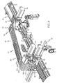
- the overhead diverter assembly 16 includes a frame 33 through which drive shafts 26, 28 and 30 of servo motors 32, 34 and 36 extend.
- Each servo motor 32, 34 and 36 is used to drive the respective flighted conveyor assembly 38, 40 and 42 and is controlled by the control system 45 ( FIG. 1 ).
- Each flighted conveyor assembly 38, 40 and 42 includes a timing belt pair 44a and 44b, 46a and 46b, and 48a and 48b and trains 54, 56 and 58 of flights.
- the timing belt pairs, 44a and 44b, 46a and 46b, and 48a and 48b may each be separately driven by its respective servo motor 32, 34 and 36.
- the servo motors 32, 34 and 36 may move their respective flighted conveyor assembly 38, 40 and 42 using idler sprockets and drive sprockets, each having teeth that mesh with teeth integrally formed in the timing belts 44a, 44b, 46a, 46b, 48a and 48b.
- Idler sprockets and drive sprockets may be arranged concentric to their drive shafts.
- the drive sprockets may be connected to their drive shafts by a key or other torque transmitting feature.
- the idler sprockets may spin freely around their drive shafts due to a bearing or bushing between the idler sprocket and the drive shaft.
- the servo motor 32 may drive the timing belts 44a and 44b.
- Drive sprockets may be keyed to the drive shaft 26 for rotation therewith which are used to move the timing belts 44a and 44b.
- the timing belts 44a and 44b may also routed over idler sprockets associated with the other drive shafts 28 and 30 to allow the timing belts 44a and 44b to move independently of the other drive shafts 28 and 30.
- the servo motor 34 may drive the timing belts 46a and 46b.
- Drive sprockets may be keyed to the drive shaft 28 for rotation therewith which are used to move the timing belts 46a and 46b.
- the timing belts 46a and 46b may also be trained over idler sprockets associated with the other drive shafts 26 and 30 to allow the timing belts 46a and 46b to move independently of the other drive shafts 26 and 30.
- the servo motor 36 may drive the timing belts 48a and 48b.
- Drive sprockets may be keyed to the drive shaft 30 for rotation therewith which are used to move the timing belts 48a and 48b.
- the timing belts 48a and 48b may also be trained over idler sprockets associated with the other drive shafts 26 and 28 to allow the timing belts 48a and 48b to move independently of the other drive shafts 26 and 28. It should be noted that while timing belts are described above, other mechanisms may be used, such as smooth flat belts, V-type belts, cables, chains, and the like.
- Trains 54, 56 and 58 of flights 60 are each directly connected to a respective pair of timing belts 44a and 44b, 46a and 46b, and 48a and 48b.
- Train 54 of flights 60 is connected directly to timing belts 44a and 44b for movement therewith
- train 56 of flights 60 is connected directly to timing belts 46a and 46b for movement therewith
- train 58 of flights 60 is connected directly to timing belts 48a and 48b for movement therewith. Movement of each train 54, 56 and 58 may be independently controlled by their associated servo motor 32, 34 and 36.
- each servo motor 32, 34 and 36 may independently control movement of its respective flighted conveyor assembly 38, 40 and 42 and associated timing belts 44a and 44b, 46a and 46b, and 48a and 48b
- a single servo motor 32, 34 and 36 may also control movement of multiple flighted conveyor assemblies 38, 40 and 42, for example, to lock movement of two or more of the flighted conveyor assemblies 38, 40 and 42 together.
- the drive sprockets and idler sprockets may have differing states to allow one of the servo motors 32, 34 and 36 to control multiple ones of the flighted conveyor assemblies 38, 40 and 42.
- more or less timing belts and servo motors than those illustrated may be used.
- a train may be connected to a single timing belt, or more than a pair of timing belts, such as three or four or more timing belts.
- FIG. 4 illustrates exemplary trains 54 and 58 of flights 60 connected to their respective flighted conveyor assemblies 38 and 42 and FIG. 5 illustrates a single flight 60 in isolation. While only trains 54 and 58 are shown in FIG. 4 , the other train 56 may include similar components as trains 54 and 58.
- the term "train of flights” is meant to include a series of flights that are connected directly to one of the flighted conveyor assemblies 38, 40 and 42 for movement therewith. Each flight 60 may be separately connected to its respective flighted conveyor assembly 38, 40 and 42 or multiple flights 60 may be connected directly together (e.g., using a hinged connection) and then connected to the respective flighted conveyor assembly 38, 40 and 42.
- each flight 60 is U-shaped in cross section and includes a forward retaining flight member 62 and a rearward retaining flight member 64 that are connected together by a base member 66 extending between the forward retaining flight member 62 and the rearward retaining flight member 64.
- the base member 66 includes connection structure (e.g., openings 68 and 70) that are located to connect to the timing belts 44a and 44b, 46a and 46b, or 48a and 48b associated with the respective flighted conveyor assembly 38, 40 and 42.
- the flights may not be U-shaped.
- the flights may include a forward retaining flight member and a rearward retaining flight member that are both connected directly to their respective timing belts without a base member.
- the flights may also be constructed by using the forward retaining member 62 or the rearward retaining member 64 and may optionally include the base member 66 to form an L-shaped construction.
- the flights may also include the forward retaining member 62 or the rearward retaining member 64 without the base member 66.
- the flights 60 may be connected to the timing belts 44a and 44b, 46a and 46b, or 48a and 48b using any suitable connection such as screws, rivets, snaps, adhesive, welding, magnets, etc. or could me molded integrally to their respected belts.
- the attachment may be configured to break or shear away in the event of jamming or malfunction.
- the flights 60 include a first open end 72 and an opposite, second open end 74.
- the first open end 72 allows for ingress of the product and the second open end 74 allows for egress of the product during a pass through operation.
- the forward retaining flight member 62 and the rearward retaining flight member 64 each taper outwardly away from each other, increasing in width (in the conveying direction) from a central portion 76 of the flights 60.
- the base member 66 may increase in thickness from the first open end 74 toward the central portion 76 and the second open end 74 to the central portion 76 (e.g., at portions 77 and 79).
- a cross sectional entrance area at the first open end 72 and a cross sectional exit area at the second open end 74 may be greater than a cross sectional area at the central portion 76 of the flights 60.
- the cross sectional areas at the first and second open ends may be about the same as the cross sectional area at the central portion 76.
- the cross-sectional area may be largest at the first open end 72 and substantially smaller at the central portion 76 and the second open end 74.
- the trains 54 and 58 may include flights 60 having about the same dimensions and may be substantially equally spaced in the conveying direction.
- the flights 60 of the trains 54 and 58 have about the same length in the cross conveying direction such that, while they may be connected directly only to timing belts 44a and 44b for train 54 and timing belts 48a and 48b for train 58, they extend across and over each of the timing belts 44a and 44b, 46a and 46b, and 48a and 48b.
- timing belts 46a, 46b, 48a and 48b can move relative to the train 54 and timing belts 44a, 44b, 46a and 46b can move relative to the train 58, allowing for movement of each train of flights 60 relative to the other trains of flights 60.
- This arrangement also allows two or more of the trains 54, 56 and 58 to align their flights 60 in single file, one flight 60 adjacent the next in the conveying direction.
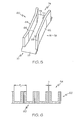
- FIG. 6 illustrates a section view through a center of the train 54 of flights 60.
- Any suitable number of flights 60 per train 54, 56 and 58 may be used.
- each train 54, 56 and 58 may include the same number of flights 60 or at least one, two or three trains may include different numbers of flights 60.
- each train 54, 56 and 58 includes 14 flights. However, more or less than 14 flights may be utilized.
- the train 56 of flights 60 has a substantially constant pitch P1 between the adjacent flights 60.
- the pitch P1 may be measured between equivalent points on adjacent flights 60.
- the pitch P1 may be between about 30-60 millimeters, such as about 40 millimeters, or such as about 50 millimeters.
- a clearance distance D between adjacent flights is maintained at about four millimeters or more, which can provide space between adjacent trains 54 and 58 and avoid collisions during operation.
- the clearance distance D may be less than four millimeters in some embodiments.
- the clearance distance D may be about zero, in some embodiments.
- the flights 60 may be formed using any suitable process or combination of processes, such as casting, molding, machining, etc. Any suitable material may be used to form the flights 60, such as various metals and plastics.
- One exemplary plastic material having low-frictional properties is polyoxymethylene (POM).
- the flights 60 are used to divert product to the cassettes 22.
- the cassettes 22 may include a front wall 78, a rear wall 80 and side walls 82 and 84 extending between the front wall 78 and the rear wall 80.
- the cassettes 22 have a closed bottom 86 with multiple product receptacles (e.g., holding trays 88) arranged side-by-side from the front wall 78 to the rear wall 80.
- Retaining walls 90 extend substantially transverse to and between the side walls 82 and 84.
- Each product holding tray 88 is shaped to retain a product within the individual product holding tray 88.
- the cassettes 22 may include multiple columns and multiple rows of holding trays 88.
- cartons or boxes may be provided having a volume for holding one or more products therein (e.g., in a stacked fashion).
- FIG. 8 illustrates a section view through a center of the cassette 22.
- any suitable number of product holding trays 88 may be used.
- each cassette 22 may include the same number of product holding trays 88, or at least some of the cassettes may include different numbers of product holding trays 88.
- each cassette 22 includes four product holding trays 88. However, more or less than four product holding trays 88 may be utilized.
- the cassettes 22 have a substantially constant pitch P2 between adjacent product holding trays 88.
- the pitch P2 of the cassettes 22 may be measured between equivalent points on adjacent product holding trays 88.
- the pitch P2 may be between about 30-60 millimeters, such as about 40 millimeters, such as about 50 millimeters.
- the pitch of the cassettes 22 matches the pitch of the trains 54, 56 and 58 of flights 60. In other embodiments, the pitch of the cassettes 22 may be different than the pitch of the trains 54, 56 and 58 of flights 60.
- the flighted conveyor assemblies 38, 40 and 42 and their respective trains may each have four primary product handling modes: (1) a diverting mode, (2) a cassette filling mode, (3) a transition from diverting mode to cassette filling mode, and (4) a transition from cassette filing mode to diverting mode constituting a complete cycle through the overhead diverter assembly 16.
- the trains 56, 58 and 54 are illustrated in the various modes with the train 56 in the diverting mode, the train 58 in the cassette filling mode and the train 54 in the transition from the cassette filling mode to the diverting mode.
- a diverting operation is illustrated where a trailing retaining flight member 64 of the train 56 is used in diverting a product 92 from the product conveyor 18.
- the train 56 may be referred to as the diverting train 56.
- the product conveyor 18 conveys the product 92 into a tunnel 93 that is formed between a leading retaining flight member 62 and the trailing retaining flight member 64.
- the diverting train 56 is controlled by input from a sensor 65 ( FIG. 1 ), e.g., an optical eye, laser sensor, etc. that whose output (or lack thereof) is used in indexing the diverting train 56 with a profiled move that is equal to the flight pitch for each product 92.
- the terms "profiled move” and “profiled motion” broadly refer to a controlled motion, such as a controlled motion having varying velocity.
- the profiled move is an indexing motion (e.g., a start and stop type motion).
- the product 92 is then picked or stripped from the product conveyor 18 and pushed by the overhead flight 60 of the diverting train 56 to a transport containment device 94.
- the transport containment device 94 is in the form of a smooth dead plate.
- the dead plate 94 angles downwardly from an elevation adjacent the product conveyor 18 to an elevation slightly above the cassettes 22.
- Other transport containment devices include vacuum nozzles, grippers, etc. that are used to retain the products 92 within their respective overhead flights 60.
- Products 92 can be diverted on demand by rapidly indexing the flights 60 of the diverting train 56 as the product 92 is carried by the product conveyor 18. Timing of the indexing motion can be selected for gaining control of the product 92 (e.g., using the sensor 65) and pushing it substantially perpendicular to the original direction of travel on the product conveyor 18.
- the indexing flight 60 drags on the side of the product 92 and the friction between the flight 60 and the product 92 reduces the speed of the product 92 traveling along the product conveyor 18.
- the high acceleration of the indexing flight 60 generates enough frictional force to completely stop the product before the product travels the entire length of the flight 60 and exits the open end 74. In these embodiments, no stop plates are needed to stop the conveying motion of the product 92.
- the product may be slowed down by friction with the flight 60 and the motion of the product can be arrested upon collision with a guide rail 95 ( FIG. 3 ) that extends along a length of the transport containment device 94.
- the train 58 of flights 60 transitions from the diverting mode to the cassette filling mode, traveling to a transfer location 96. (As shown, the train 58 has already transitioned from the diverting mode to the cassette filling mode.) In this instance, the train 58 may be referred to as the cassette filling train 58.
- the cassette filling train 58 of flights 60 carrying the diverted product 92 may be moved in synch behind the train 54 which may be nearly complete with cassette filling.
- the cassette filling train 58 deposits the products 92 diverted into the cassettes 22 at the transfer location 96.
- the motion of the cassettes 22 may be electronically geared to the motion of the cassette filling train 58 carrying the diverted products 92 along the dead plate 94, which can allow products 92 to drop (e.g., due to gravity) one at a time into respective product holding trays 88.
- additional mechanisms may be employed to aid in the transfer of the product 92 from the flight 60 to the cassette 22, such as a mechanical stripper bar that pulls the product 92 from the flight 60.
- a jet of compressed air may be used to push product 92 from the flight 60.
- a vacuum can be used to pull product 92 into the cassette 22 and may be used to hold the product in the cassette 22.
- a synchronizing system (e.g., a timing belt assembly 98) may be used to control the motion of the cassettes 22 during the transfer operation of products 92 from the cassette filling train 58 of flights 60 to the cassettes 22.
- the timing belt assembly 98 includes a timing belt 100 and a motor 102 ( FIG. 9 ) that controls movement of the timing belt 100.
- the motor 102 may be controlled by the control system 45, for example.
- the cassettes 22 are conveyed by the cassette conveyor 24 prior to cassette 22 engagement with the timing belt assembly 98.
- the cassette conveyor 24 may be operating at a higher speed V 1 than the cassette motion due to the speed V 2 of the timing belt 100 at the transfer location 96, which can allow empty cassettes 22 to cue up against each other in a line upstream of the timing belt assembly 98 and then decouple or distance apart from each other once released by the timing belt assembly 98.
- the pitch between the flights 60 and the cassettes 22 need not be the same.
- the flight pitch may be 50 mm and the cassette pitch may be 40 mm.
- the cassettes 22 may be driven synchronously with the flights 60 above such that the flight 60 containing product 92 is above (e.g., directly above) the cassette holding tray at the point of transfer where the transport containment device 94 ends.
- the speed of the cassette filling train 58 of flights 60 may be proportional to a distance between the cassette filling train 58 and the diverting train 56 diverting the product 92.
- the cassette filling train 58 may decelerate.
- the cassette filling train 58 may accelerate.
- the maximum positive acceleration of the cassette filling train 58 and timing belt assembly 98 may be limited to avoid creating gaps between cued cassettes 22 entering the timing belt assembly 98.
- This maximum acceleration may be limited to less than the coefficient of kinetic friction between the cassettes 22 and the cassette conveyor belt 24 multiplied by gravitational acceleration.
- the kinetic coefficient of friction between the cassette conveyor belt 24 and the cassettes 22 may be determined as follows: The conveyor belt 24 is driven at full production speed. The cassette 22 riding on top of the moving conveyor belt 24 is fed into a linear force gauge that is held rigid with respect to the moving conveyor belt 24. The frictional force generated between the cassette 22 and belt 24 is measured directly by the force imparted by the cassette on the force gauge. The coefficient of friction is determined by dividing the measured friction force by the normal force. In this case, the normal force between the cassette and belt is the mass of cassette multiplied by gravitational acceleration.
- the train 54 of flights 60 ( FIG. 9 ), once finished with the cassette filling operation, transitions from the cassette filling mode to the diverting mode.
- the train 54 of flights 60 is moved in coordination with the movement of the diverting train 56 so that constant spacing is maintained between the trains 54 and 56.
- the train 54 may be referred to as the cued train 54, which is awaiting its turn to divert product 92.
- the cued train 54 may move adjacent (i.e., catch up to) the diverting train 56 such that the pitch between the leading most flight 60 of the cued train 54 and the trailing most flight 60 of the diverting train 56 is substantially equal to the pitch P1 between adjacent flights 60 of the individual trains 54 and 56.
- an exemplary embodiment of a product handling system 120 includes multiple product lines (e.g., a Product 1 product line 122, a Product 2 product line 124 and a Product 3 product line 126).
- the Product 1, Product 2 and Product 3 may be provided at product source locations 128, 130 and 132.
- the product source locations 128, 130 and 132 may be, for example, a product converting line or a feeder system that supplies the product from bulk, cassettes, surge supply, etc.
- the Products 1, 2 and 3 may then be delivered to one or more overhead diverter assemblies 146, 148 and 150, each of which may be the same as or similar to the overhead diverter assembly 16 described above.
- the overhead diverter assemblies 146, 148 and 150 may divert at least some or all of their respective Product 1, 2 or 3 and the cassettes of diverted products may be sent to a multi-pack cartoner 160, where a mix of the various products may be packaged together into a package.
- One or more of the diverter assemblies 146, 148 and 150 may also allow their respective Product 1, 2 or 3 to pass through the overhead diverter assemblies 146, 148 and 150. Such pass through of the Products 1, 2 or 3 may be sent to a single pack cartoner 152, 154 and 156, which can be used to pack a single type of the Products 1, 2 or 3 into its own carton.
- the single pack cartoners 152, 154 and/or 156 may be replaced by other equipment having a demand for non-diverted product.
- additional downstream equipment such as a wrapper, printer, perforator, shrink wrapping, perfume addition, followed by other steps may be employed.
- the overhead diverter assemblies 146, 148 and/or 150 may be used to divert products in work on a converting line to enable producing products with varying stages of completion.
- the single pack cartoners 152, 154 and/or 156 may also be replaced with other packaging equipment, such as baggers, tray loaders, bundlers, etc.
- the multi-pack cartoner 160 may also be replaced by other packaging equipment, bulk storage, etc.
- multiple overhead diverter assemblies may be placed in series to divert product to multiple, downstream stations packing and/or otherwise.
- cassettes 22 are described above, in alternative embodiments, the cassettes could be a tray with no separate or divided holding trays to separate products. In some embodiments, the cassettes may be replaced by a continuous chain or belt.
- the diverted products could be transported by other means after the transport containment device 94 such as conveyor, air conveying, vibratory feed, etc.
- the diverted products could also be fed into bulk or directly loaded into cartons, bags, or other packaging.
- the diverted products could be fed into another downstream process or packaging step such as printing, perforating, wrapping, banding, shrink wrapping, perfume addition, etc.
- the above-described systems and methods for handling products utilize an overhead diverter assembly for use in diverting some, but in some instances not all, product provided from a product supply.
- the passing product may be delivered to a first packaging location and the diverted product may be delivered to a second packaging location that is different from the first packaging location.
- the overhead diverter assemblies may utilize a rapid indexing action that picks the product from a supply conveyor while reducing damage to the product during the diverting process.
Landscapes
- Engineering & Computer Science (AREA)
- Mechanical Engineering (AREA)
- Attitude Control For Articles On Conveyors (AREA)
- Branching, Merging, And Special Transfer Between Conveyors (AREA)
Claims (9)
- Produktumschlagsystem (10), umfassend:eine Produktfördereinrichtung (18), die in der Lage ist, mehrere Produkte zu transportieren,eine obenliegende Ablenkeinrichtung (16), dadurch gekennzeichnet, dass die obenliegende Ableiteinrichtung (16) Folgendes umfasst:ein Stollenband (38, 40, 42), das im Wesentlichen senkrecht zur Produktfördereinrichtung (18) angeordnet ist, und dadurch, dass das Stollenband (38, 40, 42) einen Stollen (60) umfasst,eine Transporteinschlussvorrichtung (94), die mindestens teilweise unter dem Stollenband (38, 40, 42) angeordnet ist, undein Steuerungssystem (45), das den obenliegenden Ablenker (16) so betreibt, dass das Stollenband (38, 40, 42) einen Ablenkmodus und einen Kassettenfüllmodus aufweist, wobei, wenn das Stollenband (38, 40, 42) im Ablenkmodus ist, sich der Stollen (60) in einer profilierten Bewegung bewegt, um das Produkt von der Produktfördereinrichtung (18) an einer Stelle unterhalb des obenliegenden Ablenkers (16) aufzunehmen, und das Produkt entlang der Transporteinschlussvorrichtung (94) transportiert.
- Produktumschlagsystem nach Anspruch 1, wobei der Stollen (60) mindestens einen Abschnitt eines Tunnels (93) bildet, der ein erstes offenes Ende (72), durch das das Produkt in den Tunnel (93) eintritt, während es entlang der Produktfördereinrichtung (18) läuft, und ein gegenüberliegendes zweites offenes Ende (74) bildet, wobei während des Ablenkmodus die profilierte Bewegung des Stollens (60) eine richtungsweisende Bewegung ist, die mindestens einen Abschnitt des Produkts daran hindert, durch das zweite offene Ende (74) zu gelangen, so dass das Produkt aufgenommen und entlang der Transporteinschlussvorrichtung (94) transportiert wird.
- Produktumschlagsystem nach Anspruch 1 oder 2, wobei der Stollen (60) ein Teil einer Reihe verbundener Stollen ist, die mit dem Stollenband (38, 40, 42) verbunden sind.
- Produktumschlagsystem nach Anspruch 3, wobei jeder Stollen (60) der Reihe verbundener Stollen erste und zweite Rückhaltestollenelemente aufweist, die so miteinander verbunden sind, dass sie einen U-förmigen Stollen bilden.
- Produktumschlagsystem nach Anspruch 3, wobei die Stollenreihe eine erste Reihe erster Stollen ist und das Stollenband ein erstes Stollenband ist, wobei die obenliegende Ablenkeinrichtung ferner Folgendes umfasst:eine zweite Reihe zweiter Stollen, die mit einem zweiten Stollenband verbunden sind, undeine dritte Reihe dritter Stollen, die mit einem dritten Stollenband verbunden sind.
- Produktumschlagsystem nach Anspruch 5, ferner umfassend:ein erstes Antriebssystem, das wirkend mit dem ersten Stollenband verbunden ist und das erste Stollenband in seinem Ablenkmodus bewegt,ein zweites Antriebssystem, das wirkend mit dem zweiten Stollenband verbunden ist und das zweite Stollenband in seinem Ablenkmodus bewegt, undein drittes Antriebssystem, das wirkend mit dem dritten Stollenband verbunden ist und das dritte Stollenband in seinem Ablenkmodus bewegt.
- Produktumschlagsystem nach Anspruch 6, wobei das Steuerungssystem (45) den obenliegenden Ablenker so betreibt, dass, wenn das erste Stollenband, das die erste Reihe erster Stollen aufweist, in seinem Ablenkmodus ist,
mindestens ein erster Stollen mindestens einen Abschnitt eines Tunnels bildet, um zu ermöglichen, dass das Produkt, das entlang der Produktfördereinrichtung (18) bewegt wird, an einer anderen Stelle in den Tunnel eintritt,
mindestens ein zweiter Stollen der zweiten Reihe zu einer Übertragungsstelle bewegt wird, wo, wenn sich das zweite Stollenband in einem Kassettenfüllmodus befindet, der mindestens eine zweite Stollen an eine Produktkassette angrenzt, um ein Produkt von dem mindestens einen zweiten Stollen in die Produktkassette zu übertragen, und
eine dritte Reihe dritter Stollen von der Übertragungsstelle weg und zur ersten Reihe erster Stollen hin bewegt wird. - Produktumschlagsystem nach Anspruch 6, wobei das Steuerungssystem (45) den obenliegenden Ablenker so betreibt, dass, wenn das erste Stollenband, das die erste Reihe erster Stollen aufweist, in seinem Ablenkmodus ist,
mindestens ein erster Stollen mindestens einen Abschnitt eines Tunnels bildet, um zu ermöglichen, dass das Produkt, das entlang der Produktfördereinrichtung (18) bewegt wird, an einer anderen Stelle in den Tunnel eintritt,
mindestens ein zweiter Stollen der zweiten Reihe zu einer Übertragungsstelle bewegt wird und
mindestens ein dritter Stollen der dritten Reihe zur Übertragungsstelle bewegt wird, wo, wenn sich das dritte Stollenband in einem Kassettenfüllmodus befindet, der mindestens eine dritte Stollen an eine Produktkassette angrenzt, um ein Produkt von dem mindestens einen dritten Stollen in die Produktkassette zu übertragen. - Produktumschlagsystem nach einem der Ansprüche 1 bis 8, wobei das Produkt ein eingewickeltes Tamponprodukt ist.
Applications Claiming Priority (2)
| Application Number | Priority Date | Filing Date | Title |
|---|---|---|---|
| US13/047,355 US8448776B2 (en) | 2011-03-14 | 2011-03-14 | Apparatus for diverting products and methods of handling products |
| PCT/US2012/029000 WO2012125679A1 (en) | 2011-03-14 | 2012-03-14 | Apparatus for diverting and handling products |
Publications (2)
| Publication Number | Publication Date |
|---|---|
| EP2686247A1 EP2686247A1 (de) | 2014-01-22 |
| EP2686247B1 true EP2686247B1 (de) | 2015-01-28 |
Family
ID=45937569
Family Applications (1)
| Application Number | Title | Priority Date | Filing Date |
|---|---|---|---|
| EP12713445.0A Not-in-force EP2686247B1 (de) | 2011-03-14 | 2012-03-14 | Vorrichtung zum ablenken und handhaben von produkten |
Country Status (4)
| Country | Link |
|---|---|
| US (1) | US8448776B2 (de) |
| EP (1) | EP2686247B1 (de) |
| CA (1) | CA2849408A1 (de) |
| WO (1) | WO2012125679A1 (de) |
Cited By (1)
| Publication number | Priority date | Publication date | Assignee | Title |
|---|---|---|---|---|
| CN109803893A (zh) * | 2016-08-10 | 2019-05-24 | 通用派克公司 | 用于包装小袋的设备和方法 |
Families Citing this family (16)
| Publication number | Priority date | Publication date | Assignee | Title |
|---|---|---|---|---|
| GB201007491D0 (en) * | 2010-05-05 | 2010-06-23 | Quin Systems Ltd | Conveyors |
| CA2781281A1 (en) * | 2011-06-24 | 2012-12-24 | Delkor Systems, Inc. | Bulk product diverter |
| JP6181944B2 (ja) * | 2013-03-01 | 2017-08-16 | 株式会社オシキリ | パン包装装置及びパン搬送システム |
| US9540127B2 (en) | 2015-06-09 | 2017-01-10 | The Procter & Gamble Company | Drive mechanism and methods of grouping articles |
| US9663305B2 (en) | 2015-06-09 | 2017-05-30 | The Procter & Gamble Company | Method of grouping articles into arrays of various configurations |
| US9540183B2 (en) | 2015-06-09 | 2017-01-10 | The Procter & Gamble Company | Nestable transport members and a corresponding track |
| US9580254B2 (en) | 2015-06-09 | 2017-02-28 | The Procter & Gamble Company | Apparatus for grouping articles into arrays of various configurations |
| US9573771B2 (en) | 2015-06-09 | 2017-02-21 | The Procter & Gamble Company | Systems, apparatus, and methods for grouping articles into arrays of various configurations |
| US9580253B2 (en) | 2015-06-09 | 2017-02-28 | The Procter & Gamble Company | Adjustable carriage for transporting articles of various sizes and a grouping apparatus comprising the same |
| US10689202B2 (en) | 2018-05-29 | 2020-06-23 | The Procter And Gamble Company | Apparatus for controlled transport of articles along a path |
| US10717606B2 (en) | 2018-05-29 | 2020-07-21 | The Procter And Gamble Company | Method of independently controlling motion of movers along a path |
| US10919705B2 (en) | 2018-05-29 | 2021-02-16 | The Procter And Gamble Company | Apparatus that controls motion of independent movers along a path |
| US10696488B2 (en) | 2018-05-29 | 2020-06-30 | The Procter And Gamble Company | Apparatus that controls motion of proximate independent movers along a path |
| CN109178445B (zh) * | 2018-07-23 | 2021-12-07 | 武汉人天包装自动化技术股份有限公司 | 一种皮带卡子可快换的同步带式环链 |
| JP7195990B2 (ja) * | 2019-03-25 | 2022-12-26 | 大和エンジニアリング株式会社 | 板状部材の搬送システム |
| DE102020117315A1 (de) * | 2020-07-01 | 2022-01-05 | Focke & Co. (Gmbh & Co. Kg) | Verfahren und Vorrichtung zum Handhaben von (Hygiene-)Produkten |
Family Cites Families (17)
| Publication number | Priority date | Publication date | Assignee | Title |
|---|---|---|---|---|
| US4768642A (en) | 1987-06-16 | 1988-09-06 | Kimberly-Clark Corporation | Multiple conveyors with overlapping material handling device paths |
| US5127209A (en) | 1990-11-15 | 1992-07-07 | Kimberly-Clark Corporation | Multi-purpose stacker with overlapping material handling devices |
| DE4201080A1 (de) | 1992-01-17 | 1993-07-22 | Ostma Maschinenbau Gmbh | Vorrichtung zum beschicken einer verpackungsaufnahme z. b. eines offenen kartons |
| FR2710317B1 (fr) * | 1993-09-24 | 1996-04-12 | Api | Dispositif pour la formation de lots de produits en vue de leur conditionnement. |
| US5460258A (en) * | 1993-12-17 | 1995-10-24 | Tisma Machinery Corporation | Automatic packaging machine with random input and a defined output |
| ITBO940215A1 (it) * | 1994-05-16 | 1995-11-16 | Baumer Srl | Sistema per disporre in passo e/o distanziare e compattare longitudinalmente file di oggetti allineati trasversalmente |
| DE19522189C2 (de) | 1995-06-19 | 1997-08-14 | Schubert Gerhard Gmbh | Gruppier- und Puffervorrichtung |
| IT1299948B1 (it) * | 1998-04-02 | 2000-04-04 | Azionaria Costruzioni Acma Spa | Metodo e dispositivo per la formazione di gruppi di articoli appiattiti. |
| IE990851A1 (en) | 1998-10-19 | 2000-06-28 | Burton S Foods Holdings Ltd | A method and apparatus for handling cookies |
| JP2003095421A (ja) * | 2001-09-26 | 2003-04-03 | Ishida Co Ltd | 搬送装置 |
| DE10150496A1 (de) * | 2001-10-16 | 2003-04-24 | Winkler & Duennebier Ag | Verfahren und Vorrichtung zum definierten Ablegen von Produkten aus einer Fächerkette |
| JP3974409B2 (ja) * | 2002-01-22 | 2007-09-12 | 株式会社イシダ | 搬送装置及びそれを備えた箱詰め装置 |
| US7533768B2 (en) * | 2002-03-27 | 2009-05-19 | Douglas Machine, Inc. | Retractable transfer device metering apparatus and methods |
| US6955665B2 (en) | 2002-05-23 | 2005-10-18 | The Procter & Gamble Company | Tampon wrapper with improved opening means |
| MXPA05006175A (es) * | 2002-12-09 | 2006-02-17 | Planet Products Corp | Sistema y metodo de carga de salchichas de capas multiples. |
| US6925784B2 (en) | 2003-09-11 | 2005-08-09 | The Procter & Gamble Company | Flexible manufacturing system for consumer packaged products |
| WO2007127486A2 (en) | 2006-04-28 | 2007-11-08 | Meadwestvaco Packaging Systems Llc | Adjustable lane assembly |
-
2011
- 2011-03-14 US US13/047,355 patent/US8448776B2/en active Active
-
2012
- 2012-03-14 WO PCT/US2012/029000 patent/WO2012125679A1/en not_active Ceased
- 2012-03-14 EP EP12713445.0A patent/EP2686247B1/de not_active Not-in-force
- 2012-03-14 CA CA2849408A patent/CA2849408A1/en not_active Abandoned
Cited By (1)
| Publication number | Priority date | Publication date | Assignee | Title |
|---|---|---|---|---|
| CN109803893A (zh) * | 2016-08-10 | 2019-05-24 | 通用派克公司 | 用于包装小袋的设备和方法 |
Also Published As
| Publication number | Publication date |
|---|---|
| US20120234647A1 (en) | 2012-09-20 |
| CA2849408A1 (en) | 2012-09-20 |
| US8448776B2 (en) | 2013-05-28 |
| WO2012125679A1 (en) | 2012-09-20 |
| EP2686247A1 (de) | 2014-01-22 |
Similar Documents
| Publication | Publication Date | Title |
|---|---|---|
| EP2686247B1 (de) | Vorrichtung zum ablenken und handhaben von produkten | |
| US10647457B2 (en) | Folding device, packaging facility for articles, and method for folding side flaps of external cardboard packagings | |
| US8096409B2 (en) | Apparatus and method for transporting products, having a linear drive mechanism | |
| CN104603012B (zh) | 用于包装机的供入设备 | |
| US20150158611A1 (en) | Variable pitch packaging apparatus and methods | |
| US20040195074A1 (en) | Conveyance unit and boxing unit having the same | |
| GB2218679A (en) | Apparatus for forming groups of articles, particularly for automatic packaging lines | |
| MX2014000014A (es) | Metodo y dispositivo lineal para manejar articulos. | |
| US9751699B2 (en) | Article feed system for aligning and singulating articles | |
| MXPA04009400A (es) | Dispositivo de transferencia retraible para un aparato de medicion. | |
| US20130291493A1 (en) | Boxing method and device intended to sequentially box batches of products inside packaging receptacles | |
| US20050076617A1 (en) | Multi-product accumulating and packing system | |
| GB2561826A (en) | Improvements to packaging machines | |
| KR101909266B1 (ko) | 번들 포장용 고속 스태킹장치 | |
| EP3003873A1 (de) | Vorrichtung und verfahren zur bildung von verpackungseinheiten | |
| PL1997737T3 (pl) | Urządzenie pakujące i podające do grupowania wyrobów | |
| EP2501633B1 (de) | Rotierender lader für stangenartig angeordnete produkte | |
| US6990783B2 (en) | Product packing machine | |
| US6622851B1 (en) | Conveyor section arrangement in a filling station | |
| JP5232111B2 (ja) | 物品供給装置 | |
| EP2611719A1 (de) | Verfahren und system zur gruppierung von zu verpackenden produkten | |
| US6928789B2 (en) | Assembly for collecting together different goods | |
| US6557693B1 (en) | Conveyor section arrangement for containers being filled with items or bulk material at a filling station | |
| CN213677384U (zh) | 一种纸盒自动输送排列装置 | |
| JP4887401B2 (ja) | 多列分配装置 |
Legal Events
| Date | Code | Title | Description |
|---|---|---|---|
| PUAI | Public reference made under article 153(3) epc to a published international application that has entered the european phase |
Free format text: ORIGINAL CODE: 0009012 |
|
| 17P | Request for examination filed |
Effective date: 20130725 |
|
| AK | Designated contracting states |
Kind code of ref document: A1 Designated state(s): AL AT BE BG CH CY CZ DE DK EE ES FI FR GB GR HR HU IE IS IT LI LT LU LV MC MK MT NL NO PL PT RO RS SE SI SK SM TR |
|
| DAX | Request for extension of the european patent (deleted) | ||
| GRAP | Despatch of communication of intention to grant a patent |
Free format text: ORIGINAL CODE: EPIDOSNIGR1 |
|
| INTG | Intention to grant announced |
Effective date: 20140818 |
|
| RIN1 | Information on inventor provided before grant (corrected) |
Inventor name: TECLEAB, ADAL, AMINE Inventor name: MERS-KELLY, MICHAEL, JOHN Inventor name: PAPSDORF, CLIFFORD, THEODORE |
|
| GRAS | Grant fee paid |
Free format text: ORIGINAL CODE: EPIDOSNIGR3 |
|
| GRAA | (expected) grant |
Free format text: ORIGINAL CODE: 0009210 |
|
| AK | Designated contracting states |
Kind code of ref document: B1 Designated state(s): AL AT BE BG CH CY CZ DE DK EE ES FI FR GB GR HR HU IE IS IT LI LT LU LV MC MK MT NL NO PL PT RO RS SE SI SK SM TR |
|
| REG | Reference to a national code |
Ref country code: GB Ref legal event code: FG4D |
|
| REG | Reference to a national code |
Ref country code: CH Ref legal event code: EP |
|
| REG | Reference to a national code |
Ref country code: IE Ref legal event code: FG4D |
|
| REG | Reference to a national code |
Ref country code: DE Ref legal event code: R096 Ref document number: 602012005162 Country of ref document: DE Effective date: 20150312 |
|
| REG | Reference to a national code |
Ref country code: AT Ref legal event code: REF Ref document number: 708119 Country of ref document: AT Kind code of ref document: T Effective date: 20150315 |
|
| REG | Reference to a national code |
Ref country code: AT Ref legal event code: MK05 Ref document number: 708119 Country of ref document: AT Kind code of ref document: T Effective date: 20150128 |
|
| REG | Reference to a national code |
Ref country code: NL Ref legal event code: VDEP Effective date: 20150128 |
|
| REG | Reference to a national code |
Ref country code: LT Ref legal event code: MG4D |
|
| PG25 | Lapsed in a contracting state [announced via postgrant information from national office to epo] |
Ref country code: NO Free format text: LAPSE BECAUSE OF FAILURE TO SUBMIT A TRANSLATION OF THE DESCRIPTION OR TO PAY THE FEE WITHIN THE PRESCRIBED TIME-LIMIT Effective date: 20150428 Ref country code: SE Free format text: LAPSE BECAUSE OF FAILURE TO SUBMIT A TRANSLATION OF THE DESCRIPTION OR TO PAY THE FEE WITHIN THE PRESCRIBED TIME-LIMIT Effective date: 20150128 Ref country code: BG Free format text: LAPSE BECAUSE OF FAILURE TO SUBMIT A TRANSLATION OF THE DESCRIPTION OR TO PAY THE FEE WITHIN THE PRESCRIBED TIME-LIMIT Effective date: 20150428 Ref country code: HR Free format text: LAPSE BECAUSE OF FAILURE TO SUBMIT A TRANSLATION OF THE DESCRIPTION OR TO PAY THE FEE WITHIN THE PRESCRIBED TIME-LIMIT Effective date: 20150128 Ref country code: FI Free format text: LAPSE BECAUSE OF FAILURE TO SUBMIT A TRANSLATION OF THE DESCRIPTION OR TO PAY THE FEE WITHIN THE PRESCRIBED TIME-LIMIT Effective date: 20150128 Ref country code: ES Free format text: LAPSE BECAUSE OF FAILURE TO SUBMIT A TRANSLATION OF THE DESCRIPTION OR TO PAY THE FEE WITHIN THE PRESCRIBED TIME-LIMIT Effective date: 20150128 Ref country code: LT Free format text: LAPSE BECAUSE OF FAILURE TO SUBMIT A TRANSLATION OF THE DESCRIPTION OR TO PAY THE FEE WITHIN THE PRESCRIBED TIME-LIMIT Effective date: 20150128 |
|
| PG25 | Lapsed in a contracting state [announced via postgrant information from national office to epo] |
Ref country code: AT Free format text: LAPSE BECAUSE OF FAILURE TO SUBMIT A TRANSLATION OF THE DESCRIPTION OR TO PAY THE FEE WITHIN THE PRESCRIBED TIME-LIMIT Effective date: 20150128 Ref country code: PL Free format text: LAPSE BECAUSE OF FAILURE TO SUBMIT A TRANSLATION OF THE DESCRIPTION OR TO PAY THE FEE WITHIN THE PRESCRIBED TIME-LIMIT Effective date: 20150128 Ref country code: RS Free format text: LAPSE BECAUSE OF FAILURE TO SUBMIT A TRANSLATION OF THE DESCRIPTION OR TO PAY THE FEE WITHIN THE PRESCRIBED TIME-LIMIT Effective date: 20150128 Ref country code: NL Free format text: LAPSE BECAUSE OF FAILURE TO SUBMIT A TRANSLATION OF THE DESCRIPTION OR TO PAY THE FEE WITHIN THE PRESCRIBED TIME-LIMIT Effective date: 20150128 Ref country code: IS Free format text: LAPSE BECAUSE OF FAILURE TO SUBMIT A TRANSLATION OF THE DESCRIPTION OR TO PAY THE FEE WITHIN THE PRESCRIBED TIME-LIMIT Effective date: 20150528 Ref country code: GR Free format text: LAPSE BECAUSE OF FAILURE TO SUBMIT A TRANSLATION OF THE DESCRIPTION OR TO PAY THE FEE WITHIN THE PRESCRIBED TIME-LIMIT Effective date: 20150429 Ref country code: LV Free format text: LAPSE BECAUSE OF FAILURE TO SUBMIT A TRANSLATION OF THE DESCRIPTION OR TO PAY THE FEE WITHIN THE PRESCRIBED TIME-LIMIT Effective date: 20150128 |
|
| REG | Reference to a national code |
Ref country code: DE Ref legal event code: R097 Ref document number: 602012005162 Country of ref document: DE |
|
| PG25 | Lapsed in a contracting state [announced via postgrant information from national office to epo] |
Ref country code: SK Free format text: LAPSE BECAUSE OF FAILURE TO SUBMIT A TRANSLATION OF THE DESCRIPTION OR TO PAY THE FEE WITHIN THE PRESCRIBED TIME-LIMIT Effective date: 20150128 Ref country code: LU Free format text: LAPSE BECAUSE OF FAILURE TO SUBMIT A TRANSLATION OF THE DESCRIPTION OR TO PAY THE FEE WITHIN THE PRESCRIBED TIME-LIMIT Effective date: 20150314 Ref country code: MC Free format text: LAPSE BECAUSE OF FAILURE TO SUBMIT A TRANSLATION OF THE DESCRIPTION OR TO PAY THE FEE WITHIN THE PRESCRIBED TIME-LIMIT Effective date: 20150128 Ref country code: CZ Free format text: LAPSE BECAUSE OF FAILURE TO SUBMIT A TRANSLATION OF THE DESCRIPTION OR TO PAY THE FEE WITHIN THE PRESCRIBED TIME-LIMIT Effective date: 20150128 Ref country code: DK Free format text: LAPSE BECAUSE OF FAILURE TO SUBMIT A TRANSLATION OF THE DESCRIPTION OR TO PAY THE FEE WITHIN THE PRESCRIBED TIME-LIMIT Effective date: 20150128 Ref country code: RO Free format text: LAPSE BECAUSE OF FAILURE TO SUBMIT A TRANSLATION OF THE DESCRIPTION OR TO PAY THE FEE WITHIN THE PRESCRIBED TIME-LIMIT Effective date: 20150128 Ref country code: EE Free format text: LAPSE BECAUSE OF FAILURE TO SUBMIT A TRANSLATION OF THE DESCRIPTION OR TO PAY THE FEE WITHIN THE PRESCRIBED TIME-LIMIT Effective date: 20150128 |
|
| REG | Reference to a national code |
Ref country code: CH Ref legal event code: PL |
|
| PLBE | No opposition filed within time limit |
Free format text: ORIGINAL CODE: 0009261 |
|
| STAA | Information on the status of an ep patent application or granted ep patent |
Free format text: STATUS: NO OPPOSITION FILED WITHIN TIME LIMIT |
|
| PG25 | Lapsed in a contracting state [announced via postgrant information from national office to epo] |
Ref country code: IT Free format text: LAPSE BECAUSE OF FAILURE TO SUBMIT A TRANSLATION OF THE DESCRIPTION OR TO PAY THE FEE WITHIN THE PRESCRIBED TIME-LIMIT Effective date: 20150128 |
|
| 26N | No opposition filed |
Effective date: 20151029 |
|
| REG | Reference to a national code |
Ref country code: IE Ref legal event code: MM4A |
|
| PG25 | Lapsed in a contracting state [announced via postgrant information from national office to epo] |
Ref country code: IE Free format text: LAPSE BECAUSE OF NON-PAYMENT OF DUE FEES Effective date: 20150314 Ref country code: CH Free format text: LAPSE BECAUSE OF NON-PAYMENT OF DUE FEES Effective date: 20150331 Ref country code: LI Free format text: LAPSE BECAUSE OF NON-PAYMENT OF DUE FEES Effective date: 20150331 |
|
| REG | Reference to a national code |
Ref country code: FR Ref legal event code: PLFP Year of fee payment: 5 |
|
| PG25 | Lapsed in a contracting state [announced via postgrant information from national office to epo] |
Ref country code: SI Free format text: LAPSE BECAUSE OF FAILURE TO SUBMIT A TRANSLATION OF THE DESCRIPTION OR TO PAY THE FEE WITHIN THE PRESCRIBED TIME-LIMIT Effective date: 20150128 |
|
| PG25 | Lapsed in a contracting state [announced via postgrant information from national office to epo] |
Ref country code: BE Free format text: LAPSE BECAUSE OF FAILURE TO SUBMIT A TRANSLATION OF THE DESCRIPTION OR TO PAY THE FEE WITHIN THE PRESCRIBED TIME-LIMIT Effective date: 20150128 |
|
| PG25 | Lapsed in a contracting state [announced via postgrant information from national office to epo] |
Ref country code: MT Free format text: LAPSE BECAUSE OF FAILURE TO SUBMIT A TRANSLATION OF THE DESCRIPTION OR TO PAY THE FEE WITHIN THE PRESCRIBED TIME-LIMIT Effective date: 20150128 |
|
| REG | Reference to a national code |
Ref country code: FR Ref legal event code: PLFP Year of fee payment: 6 |
|
| PG25 | Lapsed in a contracting state [announced via postgrant information from national office to epo] |
Ref country code: HU Free format text: LAPSE BECAUSE OF FAILURE TO SUBMIT A TRANSLATION OF THE DESCRIPTION OR TO PAY THE FEE WITHIN THE PRESCRIBED TIME-LIMIT; INVALID AB INITIO Effective date: 20120314 Ref country code: SM Free format text: LAPSE BECAUSE OF FAILURE TO SUBMIT A TRANSLATION OF THE DESCRIPTION OR TO PAY THE FEE WITHIN THE PRESCRIBED TIME-LIMIT Effective date: 20150128 |
|
| PG25 | Lapsed in a contracting state [announced via postgrant information from national office to epo] |
Ref country code: CY Free format text: LAPSE BECAUSE OF FAILURE TO SUBMIT A TRANSLATION OF THE DESCRIPTION OR TO PAY THE FEE WITHIN THE PRESCRIBED TIME-LIMIT Effective date: 20150128 |
|
| PG25 | Lapsed in a contracting state [announced via postgrant information from national office to epo] |
Ref country code: PT Free format text: LAPSE BECAUSE OF FAILURE TO SUBMIT A TRANSLATION OF THE DESCRIPTION OR TO PAY THE FEE WITHIN THE PRESCRIBED TIME-LIMIT Effective date: 20150528 |
|
| PG25 | Lapsed in a contracting state [announced via postgrant information from national office to epo] |
Ref country code: TR Free format text: LAPSE BECAUSE OF FAILURE TO SUBMIT A TRANSLATION OF THE DESCRIPTION OR TO PAY THE FEE WITHIN THE PRESCRIBED TIME-LIMIT Effective date: 20150128 |
|
| REG | Reference to a national code |
Ref country code: FR Ref legal event code: PLFP Year of fee payment: 7 |
|
| PG25 | Lapsed in a contracting state [announced via postgrant information from national office to epo] |
Ref country code: MK Free format text: LAPSE BECAUSE OF FAILURE TO SUBMIT A TRANSLATION OF THE DESCRIPTION OR TO PAY THE FEE WITHIN THE PRESCRIBED TIME-LIMIT Effective date: 20150128 |
|
| PG25 | Lapsed in a contracting state [announced via postgrant information from national office to epo] |
Ref country code: AL Free format text: LAPSE BECAUSE OF FAILURE TO SUBMIT A TRANSLATION OF THE DESCRIPTION OR TO PAY THE FEE WITHIN THE PRESCRIBED TIME-LIMIT Effective date: 20150128 |
|
| PGFP | Annual fee paid to national office [announced via postgrant information from national office to epo] |
Ref country code: DE Payment date: 20190226 Year of fee payment: 8 Ref country code: GB Payment date: 20190313 Year of fee payment: 8 |
|
| PGFP | Annual fee paid to national office [announced via postgrant information from national office to epo] |
Ref country code: FR Payment date: 20190213 Year of fee payment: 8 |
|
| REG | Reference to a national code |
Ref country code: DE Ref legal event code: R119 Ref document number: 602012005162 Country of ref document: DE |
|
| PG25 | Lapsed in a contracting state [announced via postgrant information from national office to epo] |
Ref country code: FR Free format text: LAPSE BECAUSE OF NON-PAYMENT OF DUE FEES Effective date: 20200331 Ref country code: DE Free format text: LAPSE BECAUSE OF NON-PAYMENT OF DUE FEES Effective date: 20201001 |
|
| GBPC | Gb: european patent ceased through non-payment of renewal fee |
Effective date: 20200314 |
|
| PG25 | Lapsed in a contracting state [announced via postgrant information from national office to epo] |
Ref country code: GB Free format text: LAPSE BECAUSE OF NON-PAYMENT OF DUE FEES Effective date: 20200314 |