EP2685557A2 - Antenne et station de base - Google Patents
Antenne et station de base Download PDFInfo
- Publication number
- EP2685557A2 EP2685557A2 EP12742676.5A EP12742676A EP2685557A2 EP 2685557 A2 EP2685557 A2 EP 2685557A2 EP 12742676 A EP12742676 A EP 12742676A EP 2685557 A2 EP2685557 A2 EP 2685557A2
- Authority
- EP
- European Patent Office
- Prior art keywords
- butler
- antenna
- ports
- hybrid coupler
- degree hybrid
- Prior art date
- Legal status (The legal status is an assumption and is not a legal conclusion. Google has not performed a legal analysis and makes no representation as to the accuracy of the status listed.)
- Granted
Links
- 238000010586 diagram Methods 0.000 description 17
- 239000011159 matrix material Substances 0.000 description 17
- 230000008859 change Effects 0.000 description 4
- 238000000034 method Methods 0.000 description 4
- 230000009977 dual effect Effects 0.000 description 3
- 230000000694 effects Effects 0.000 description 2
- 238000005516 engineering process Methods 0.000 description 2
- 230000003993 interaction Effects 0.000 description 2
- 230000004048 modification Effects 0.000 description 2
- 238000012986 modification Methods 0.000 description 2
- 230000008569 process Effects 0.000 description 2
- 238000004891 communication Methods 0.000 description 1
- 238000011161 development Methods 0.000 description 1
- 230000006872 improvement Effects 0.000 description 1
- 238000010295 mobile communication Methods 0.000 description 1
- 238000012545 processing Methods 0.000 description 1
Images


Classifications
-
- H—ELECTRICITY
- H01—ELECTRIC ELEMENTS
- H01Q—ANTENNAS, i.e. RADIO AERIALS
- H01Q3/00—Arrangements for changing or varying the orientation or the shape of the directional pattern of the waves radiated from an antenna or antenna system
- H01Q3/26—Arrangements for changing or varying the orientation or the shape of the directional pattern of the waves radiated from an antenna or antenna system varying the relative phase or relative amplitude of energisation between two or more active radiating elements; varying the distribution of energy across a radiating aperture
-
- H—ELECTRICITY
- H01—ELECTRIC ELEMENTS
- H01Q—ANTENNAS, i.e. RADIO AERIALS
- H01Q1/00—Details of, or arrangements associated with, antennas
- H01Q1/12—Supports; Mounting means
- H01Q1/22—Supports; Mounting means by structural association with other equipment or articles
- H01Q1/24—Supports; Mounting means by structural association with other equipment or articles with receiving set
- H01Q1/241—Supports; Mounting means by structural association with other equipment or articles with receiving set used in mobile communications, e.g. GSM
- H01Q1/246—Supports; Mounting means by structural association with other equipment or articles with receiving set used in mobile communications, e.g. GSM specially adapted for base stations
-
- H—ELECTRICITY
- H01—ELECTRIC ELEMENTS
- H01Q—ANTENNAS, i.e. RADIO AERIALS
- H01Q25/00—Antennas or antenna systems providing at least two radiating patterns
-
- H—ELECTRICITY
- H01—ELECTRIC ELEMENTS
- H01Q—ANTENNAS, i.e. RADIO AERIALS
- H01Q3/00—Arrangements for changing or varying the orientation or the shape of the directional pattern of the waves radiated from an antenna or antenna system
- H01Q3/26—Arrangements for changing or varying the orientation or the shape of the directional pattern of the waves radiated from an antenna or antenna system varying the relative phase or relative amplitude of energisation between two or more active radiating elements; varying the distribution of energy across a radiating aperture
- H01Q3/30—Arrangements for changing or varying the orientation or the shape of the directional pattern of the waves radiated from an antenna or antenna system varying the relative phase or relative amplitude of energisation between two or more active radiating elements; varying the distribution of energy across a radiating aperture varying the relative phase between the radiating elements of an array
- H01Q3/34—Arrangements for changing or varying the orientation or the shape of the directional pattern of the waves radiated from an antenna or antenna system varying the relative phase or relative amplitude of energisation between two or more active radiating elements; varying the distribution of energy across a radiating aperture varying the relative phase between the radiating elements of an array by electrical means
- H01Q3/40—Arrangements for changing or varying the orientation or the shape of the directional pattern of the waves radiated from an antenna or antenna system varying the relative phase or relative amplitude of energisation between two or more active radiating elements; varying the distribution of energy across a radiating aperture varying the relative phase between the radiating elements of an array by electrical means with phasing matrix
Definitions
- the present invention relates to antenna technologies, and in particular, to an antenna and a base station.
- the development of mobile communication technologies requires improvement in a base station antenna array to increase the system capacity and optimize patterns, thereby meeting the communication requirements.
- the system capacity is increased through increasing the number of sectors implemented by increasing the number of antennas.
- horizontal plane splitting is implemented on an antenna to increase the system capacity.
- the multi-beam split antenna is implemented in the form of horizontal Butler network & multi-column cell array, so as to increase the system capacity.
- Embodiments of the present invention provide an antenna and a base station for implementing splitting of beams on a vertical plane on the antenna.
- an embodiment of the present invention provides an antenna, including where the antenna array includes multiple radiating elements arranged vertically; the first BUTLER network has n input ports and m output ports, where m and n are natural numbers, n is greater than or equal to 2, m is greater than or equal to 3, and m is greater than n; the m output ports are respectively connected to at least one radiating element of the antenna array, and the radiating elements connected to the m output ports in the antenna array are arranged on a vertical plane; and the n input ports of the first BUTLER network respectively receive a path of signals, the n input ports receive n paths of signals and, after phase adjustment and amplitude adjustment by the first BUTLER network, output signals of n groups of phase distribution combination through the m output ports, each group of phase distribution combination includes m phases, each output port respectively outputs signals of one phase in each group of phase distribution combination, and the multiple radiating elements connected to the m output ports radiate n beams, where the n beams are distributed at specific angles on the vertical
- an embodiment of the present invention provides a base station, which includes a pole and the foregoing antenna, where the antenna is fixed on the pole.
- the antenna and base station provided by embodiments of the present invention, by using the first BUTLER network and the radiating elements arranged on a vertical plane connected to the first BUTLER network, implement the splitting of beams on the vertical plane.
- the antenna provided in an embodiment of the present invention includes an antenna array and a first BUTLER network.
- the antenna array includes multiple radiating elements arranged vertically.
- the antenna array includes at least one column of multiple radiating elements arranged vertically.
- the first BUTLER network has n input ports and m output ports, where m and n are natural numbers, n is greater than or equal to 2, m is greater than or equal to 3, and m is greater than n.
- the input ports are ports for connecting the first BUTLER network to a base station and implementing signal interaction with the base station; the output ports are ports for connecting the first BUTLER network to the antenna array and implementing signal interaction with the antenna array.
- the m output ports are respectively connected to at least one radiating element of the antenna array, and the radiating elements connected to the m output ports in the antenna array are arranged on a vertical plane.
- the n input ports of the first BUTLER network respectively receive a path of signals
- the n input ports receive n paths of signals and, after phase adjustment and amplitude adjustment by the first BUTLER network, output signals of n groups of phase distribution combination through the m output ports
- each group of phase distribution combination includes m phases
- each output port respectively outputs signals of one phase in each group of phase distribution combination
- the multiple radiating elements connected to the m output ports radiate n beams, where the n beams are distributed at specific angles on the vertical plane.
- n is equal to 2 or 3
- m is equal to 5.
- the first BUTLER network includes a first power divider, a second power divider, a 90-degree hybrid coupler, a first 180-degree hybrid coupler, and a second 180-degree hybrid coupler.
- An input port of the first power divider is connected to an input port of the first BUTLER network.
- An output port of the first power divider is connected to a ⁇ input port of the first 180-degree hybrid coupler, and another output port is connected to a ⁇ input port of the second 180-degree hybrid coupler.
- An output port of the 90-degree hybrid coupler is connected to a ⁇ input port of the first 180-degree hybrid coupler, and another output port is connected to a ⁇ input port of the second 180-degree hybrid coupler.
- An output port of the first 180-degree hybrid coupler is connected to an input port of the second power divider, and another output port is connected to one of the output ports.
- Two output ports of the second 180-degree hybrid coupler are respectively connected to one of the output ports.
- Two output ports of the second power divider are respectively connected to one of the output ports.
- an input port of the 90-degree hybrid coupler is connected to another input port of the first BUTLER network.
- n is equal to 2
- m is equal to 4.
- the first BUTLER network may include a third power divider, a fourth power divider, a first inverter, a second inverter, a first 90-degree hybrid coupler, and a second 90-degree hybrid coupler.
- Input ports of the third power divider and the fourth power divider are respectively connected to an input port of the first BUTLER network.
- An output port of the third power divider is connected to a first input port of the first 90-degree hybrid coupler, and another output port is connected to an input port of the first inverter.
- An output port of the fourth power divider is connected to a second input port of the first 90-degree hybrid coupler, and another output port is connected to an input port of the second inverter.
- An output port of the first inverter is connected to a first input port of the second 90-degree hybrid coupler.
- An output port of the second inverter is connected to a second input port of the second 90-degree hybrid coupler.
- Two output ports of the first 90-degree hybrid coupler are respectively connected to one of the output ports.
- Two output ports of the second 90-degree hybrid coupler are respectively connected to one of the output ports.
- the first BUTLER network may include a 90-degree hybrid coupler, where two input ports of the 90-degree hybrid coupler are respectively connected to an input port of the first BUTLER network, and two output ports are respectively connected to two output ports of the first BUTLER network.
- output ports of the first BUTLER network are respectively connected to two, three, or four radiating elements of the antenna array, or respectively connected to two, three, or four radiating elements in the antenna array by using a phase shifter.
- the phase shifter is added between a matrix network and the radiating elements so that vertical beams are capable of changing dynamically.
- the antenna array has multiple columns of multiple radiating elements arranged vertically corresponding to the first BUTLER networks, and the first BUTLER networks are respectively connected to the multiple radiating elements arranged vertically of the corresponding column.
- the antenna further includes multiple phase shifters having the number the same as the number of the first BUTLER networks, where the multiple phase shifters are m-in-m-out phase shifters, and the output ports of the first BUTLER networks are connected to input ports of the phase shifters.
- Each output port of the phase shifters is connected to at least one radiating element of the antenna array.
- the antenna further includes m second BUTLER networks, where the m second BUTLER networks are horizontal BUTLER networks, and the numbers of input ports of the m second BUTLER networks are equal to P, where P is the number of first BUTLER networks.
- Input ports of the second BUTLER networks are connected to the output ports of the first BUTLER networks, and output ports of each second BUTLER network are connected to at least two rows of parallel radiating elements in the antenna array, so that in the antenna array, the radiating elements connected to the second BUTLER networks generate P beams on the horizontal plane.
- the antenna further includes multiple phase shifters having the number the same as the number of the first BUTLER networks, where the multiple phase shifters are m-in-m-out phase shifters, the output ports of the first BUTLER networks are connected to input ports of the phase shifters, each output port of the phase shifters is connected to the input ports of the second BUTLER networks, and output ports of each second BUTLER network are connected to at least two rows of parallel radiating elements in the antenna array.
- the radiating elements are single dipole elements, orthogonal dual-polarized dipole elements, patch radiating elements, or circular radiating elements.
- the first BUTLER networks are connected to the antenna array by using a filter.
- phase shifters are connected to the antenna array by using a filter.
- the second BUTLER networks are connected to the antenna array by using a filter.
- the base station provided by embodiments of the present invention includes a pole and any one of the forgoing antennas, where the antenna is fixed on the pole.
- Embodiment 1 The following further describes the antenna and the base station in detail by referring to Embodiment 1 to Embodiment 14.
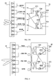
- an antenna includes an antenna array 11 and a BUTLER network 12.
- the antenna array 11 includes 10 radiating elements arranged on a vertical plane.
- the BUTLER network 12 is a 2-in-5-out matrix network, that is, there are two input ports: a first input port 121 and a second input port 122. Each output port of the BUTLER network 12 is connected to two radiating elements in the antenna array 11 by using a power divider (not shown in the figure, the same below).
- the 10 radiating elements connected to the BUTLER network 12 in the antenna array 11 are arranged on a vertical plane.
- a first path of signals which are input through the first input port 121 goes through the BUTLER network 12, generates a group of signals whose phases are a1:a2:a3:a4:a5 at five output ports and, after being transmitted by the radiating elements of the antenna array 11, splits and generates an upward beam (U_beam) bearing the first path of signals on the vertical plane, as shown by the horizontal ellipse on the left side of the radiating elements in FIG. 1A .
- a second path of signals which are input through the second input port 122 goes through the BUTLER network 12, generates another group of signals whose phases are b1:b2:b3:b4:b5 at five output ports and, after being transmitted by the radiating elements of the antenna array 11, splits and generates a downward beam (D_beam) bearing the second path of signals on the vertical plane, as shown by the down-tilting ellipse on the left side of the radiating elements in FIG. 1A , thereby generating dual beams on the vertical plane of the antenna array 11.
- D_beam downward beam bearing the second path of signals on the vertical plane
- the power amplitude ratio of the radiating elements may be adjusted depending as required, for example, 0.7/0.7/1/1/1/1/1/1/0.7/0.7.
- an antenna includes an antenna array 21 and a BUTLER network 22.
- the antenna array 21 includes 10 radiating elements arranged on a vertical plane.
- the BUTLER network 22 is a 3-in-5-out matrix network, that is, there are three input ports: a first input port 221, a second input port 222, and a third beam input port 223. Each output port of the BUTLER network 22 is connected to two radiating elements in the antenna array 21 by using a power divider.
- the 10 radiating elements connected to the BUTLER network 22 in the antenna array 21 are arranged on a vertical plane.
- M_beam middle beam bearing the second path of signals
- a third path of signals which are input through the third beam input port 223 goes through the antenna array 21, generates another group of signals whose phase distribution combination are c1:c2:c3:c4:c5 at five output ports and, after being transmitted by the 10 radiating elements arranged on a vertical plane of the antenna array 21, generates a downward beam (D_beam) bearing the third path of signals, as shown by the down-tilting ellipse on the left side of the radiating elements in FIG. 2 , thereby generating three beams on the vertical plane of the antenna array 21.
- D_beam downward beam bearing the third path of signals
- the power amplitude ratio of the radiating elements may be adjusted as required, for example, 0.7/0.7/1/1/1/1/1/0.7/0.7.
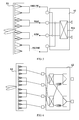
- an antenna includes an antenna array 31 and a BUTLER network 32.
- the antenna array 31 includes 10 radiating elements arranged on a vertical plane.
- the BUTLER network 32 includes a first power divider 321, a second power divider 322, a 90-degree hybrid coupler 323, a first 180-degree hybrid coupler 324, and a second 180-degree hybrid coupler 325.
- An input port of the first power divider 321 and an input port of the 90-degree hybrid coupler 323 are respectively connected to an input port of the BUTLER network 32.
- a first input port of the 90-degree hybrid coupler 323 is connected to a first input port of the BUTLER network 32
- a second input port of the 90-degree hybrid coupler 323 is zero loaded
- the input port of the first power divider 321 is connected to a second input port of the BUTLER network 32. That is to say, the BUTLER network 32 has two input ports.
- the first input port of the 90-degree hybrid coupler 323 is connected to the first input port of the BUTLER network 32
- the second input port of the 90-degree hybrid coupler 323 is connected to a second input port of the BUTLER network 32
- the input port of the first power divider 321 is connected to a third input port of the BUTLER network 32. That is to say, the BUTLER network 32 has three input ports.
- An output port of the first power divider 321 is connected to a ⁇ input port of the first 180-degree hybrid coupler 324, and another output port is connected to a ⁇ input port of the second 180-degree hybrid coupler 325.
- An output port of the 90-degree hybrid coupler is connected to a ⁇ input port of the first 180-degree hybrid coupler 324, and another output port is connected to a ⁇ input port of the second 180-degree hybrid coupler 325.
- An output port of the first 180-degree hybrid coupler 324 is connected to an input port of the second power divider 322, and another output port is connected to an output port of the BUTLER network 32.
- Two output ports of the second 180-degree hybrid coupler 325 are respectively connected to an output port of the BUTLER network 32.
- Two output ports of the second power divider 322 are respectively connected to an output port of the BUTLER network 32.
- the BUTLER network 32 in FIG. 3A is a 2-in-5-out matrix network
- the BUTLER network 32 in FIG. 3B is a 3-in-5-out matrix network
- each output port of the BUTLER network 32 is connected to two radiating elements in the antenna array 31 by using the power divider.
- the 10 radiating elements connected to the BUTLER network 32 in the antenna array 31 are arranged on a vertical plane.
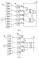
- an antenna includes an antenna array 41 and a BUTLER network 42.
- the antenna array 41 includes 8 radiating elements arranged on a vertical plane.
- the BUTLER network 42 is a 2-in-4-out matrix network, and includes a third power divider 421, a fourth power divider 422, a first inverter 423, a second inverter 424, a first 90-degree hybrid coupler 425, and a second 90-degree hybrid coupler 426.
- Input ports of the third power divider 421 and the fourth power divider 422 are respectively connected to an input port of the BUTLER network 42. As shown in FIG. 4 , the input port of the third power divider 421 is connected to a first input port of the BUTLER network 42, and the input port of the fourth power divider 422 is connected to a second input port of the BUTLER network 42.
- An output port of the third power divider 421 is connected to a first input port of the first 90-degree hybrid coupler 425, and another output port is connected to an input port of the first inverter 423.
- An output port of the fourth power divider 422 is connected to a second input port of the first 90-degree hybrid coupler 425, and another output port is connected to an input port of the second inverter 424.
- An output port of the first inverter 423 is connected to a first input port of the second 90-degree hybrid coupler 426.
- An output port of the second inverter 424 is connected to a second input port of the second 90-degree hybrid coupler 426.
- Two output ports of the first 90-degree hybrid coupler 425 are respectively connected to an output port of the BUTLER network 42; two output ports of the second 90-degree hybrid coupler 426 are respectively connected to an output port of the BUTLER network 42.
- a first path of signals which are input through the first input port of the BUTLER network 42 goes through the BUTLER network 42, generates a group of signals whose phase distribution combination is 90:-180:-90:0 at four output ports and, after being transmitted by the radiating elements of the antenna array 41, generates an upward beam bearing the first path of signals.
- a second path of signals which are input through the second input port of the BUTLER network 42 goes through the BUTLER network 42, generates another group of signals whose phase distribution combination is 0:-90:-180:90 at four output ports and, after being transmitted by the radiating elements of the antenna array 41, generates a downward beam bearing the second path of signals, thereby generating dual beams on the vertical plane of the antenna.
- an antenna includes an antenna array 51 and a BUTLER network 52.
- the antenna array 51 includes 8 radiating elements arranged on a vertical plane.
- the BUTLER network 52 is a 2-in-4-out matrix network and includes a 90-degree hybrid coupler 521, where two input ports of the 90-degree hybrid coupler 521 are respectively connected to an input port of the BUTLER network 52, and two output ports are connected to two output ports of the BUTLER network 52.
- a first path of signals which are input through a first input port of the BUTLER network 52 goes through the BUTLER network 52, generates a group of signals whose phase distribution combination is 90:-180:-90:0 at four output ports and, after being transmitted by the radiating elements of the antenna array 51, generates an upward beam bearing the first path of signals, as shown by the horizontal ellipse on the left side of the radiating elements in FIG. 5 .
- a second path of signals which are input through a second input port of the BUTLER network 52 goes through the BUTLER network 52, generates a group of signals whose phase distribution combination is 0:-90:-180:90 at four output ports and, after being transmitted by the radiating elements of the antenna array 51, generates a downward beam bearing the second path of signals, as shown by the down-titling ellipse on the left side of the radiating elements in FIG. 5 , thereby generating dual beams on the vertical plane of the antenna.
- the BUTLER network 52 uses a 90-degree hybrid coupler to implement the splitting function, thereby meeting the phase requirements respectively.
- an antenna includes an antenna array 61 and a BUTLER network 62.
- the antenna array 61 includes 12 radiating elements arranged on a vertical plane.
- the BUTLER network 62 is a 2-in-4-out matrix network, where output ports thereof are respectively connected to 3 radiating elements.
- the internal structure of the BUTLER network 62 may be the same as that of the BUTLER network provided in Embodiment 4 or Embodiment 5, which is described in detail foregoing and is not repeated here.
- an antenna includes an antenna array 71 and a BUTLER network 72.
- the antenna array 71 includes 16 radiating elements arranged on a vertical plane.
- the BUTLER network 72 is a 2-in-4-out matrix network, where output ports thereof are respectively connected to 4 radiating elements.
- the internal structure of the BUTLER network 72 may be the same as that of the BUTLER network provided in Embodiment 4 or Embodiment 5, which is described in detail foregoing and is not repeated here.
- the number of radiating elements which are connected to each output port of the BUTLER network is not limited to the cases described in the foregoing embodiments.
- the number of radiating elements may be different depending on the actual requirements.
- phase shifter is added on the basis of the embodiment in FIG. 3A .
- a phase shifter 83 is added between a BUTLER network 82 and an antenna array 81.
- the phase shifter 83 may be an N-in-N-out phase shifter.
- the phase shifter 83 in FIG. 8 is a 5-in-5-out phase shifter.
- Five input ports of the phase shifter 83 are respectively one-to-one corresponding to and connected to five output ports of the BUTLER network 82.
- Five output ports of the phase shifter 83 are connected to radiating elements of the antenna array 81, where each output port may be connected to multiple radiating elements. In this embodiment, each output port of the phase shifter 83 is connected to two radiating elements.
- phases at each port of the phase shifter 83 may change with the ratio of +2 ⁇ : ⁇ :0:- ⁇ :2 ⁇ , or with other phase ratios.
- the antenna achieves the effect of simultaneous down-tilting change of two beams of the antenna by using the phase shifter.
- phase shifter is added on the basis of the embodiment in FIG. 5 .
- an antenna includes an antenna array 91, a BUTLER network 92, and a phase shifter 93.
- the phase shifter 93 may be an N-in-N-out phase shifter.
- the phase shifter 93 in FIG. 9 is a 4-in-4-out phase shifter.
- phase shifter 93 Four input ports of the phase shifter 93 are respectively one-to-one corresponding to and connected to four output ports of the BUTLER network 92.
- Four output ports of the phase shifter 93 are connected to radiating elements of the antenna array 91, where each output port may be connected to multiple radiating elements.
- each output port of the phase shifter 93 is connected to two radiating elements.
- phases at each port of the phase shifter 93 may change with the ratio of +3 ⁇ : ⁇ :- ⁇ :3 ⁇ , or with other phase ratios.
- the antenna also achieves the effect of simultaneous down-tilting change of two beams of the antenna by using the phase shifter.
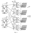
- an antenna includes an antenna array 101, first BUTLER networks 102, second BUTLER networks 103, and phase shifters 104.
- the antenna 101 is an array of 4x10 radiating elements.
- the first BUTLER network 102 and the phase shifter 104 are the same as those in the embodiment shown in FIG. 8 .
- There are two first BUTLER networks 102 namely, a left first BUTLER network 102 and a right first BUTLER network 102, which are matrix networks on two vertical planes. Output ports of the first BUTLER networks 102 are arranged on five different horizontal planes.
- there are two phase shifters 104 namely, a left phase shifter 104 and a right phase shifter 104, which are 5-in-5-out phase shifters and are respectively connected to a first BUTLER network 102.
- Second BUTLER networks 103 which are matrix networks on five different horizontal planes and are connected to output ports on different horizontal planes of the left phase shifter 104 and right phase shifter 104.
- Left input ports of the five second BUTLER networks 103 are connected to the five output ports of the left first BUTLER network 102 through the output ports of the left phase shifter 104, which implements upward beams and downward beams of a left first beam and a left second beam on the horizontal plane.
- Right input ports of the five second BUTLER networks 103 are connected to the five output ports of the right first BUTLER network 102 through the output ports of the right phase shifter 104, which implements upward beams and downward beams of a right first beam and a right second beam on the horizontal plane.
- Each output port of each second BUTLER network 103 is connected to two radiating elements on one vertical plane. As shown in FIG. 10B , the output ports of the second BUTLER network 103 on each horizontal plane are connected to an array of 4x2 radiating elements of the antenna array 101.
- the internal structure of the second BUTLER networks 103 may be the same as the internal structure of any 2-in-4-out matrix network provided in the foregoing embodiments.
- the antenna implements the function of horizontal splitting in a vertical splitting antenna by using first and second BUTLER networks, and by setting phase shifters between the horizontal matrix networks and vertical matrix networks, implements the function of down-tilting beams.
- This embodiment is basically the same as the Embodiment 10, but is different in that a first BUTLER network has four output ports, and correspondingly, there are four second BUTLER networks and an antenna array is an array of 4x12 radiating elements.
- an antenna includes an antenna array 111, first BUTLER networks 112, second BUTLER networks 113, and phase shifters 114.
- Each output port of the second BUTLER networks 113 is connected to three radiating elements on one vertical plane.
- the first BUTLER networks 112 are the same as the BUTLER network in the embodiment shown in FIG. 4 .
- This embodiment also implements horizontal and vertical splitting, and by setting phase shifters between the horizontal matrix networks and vertical matrix networks, implements the function of down-tilting beams.
- This embodiment is basically the same as the embodiment shown in FIG. 8 , but is different in that radiating elements are orthogonal dual-polarized dipole elements and there are two BUTLER networks.
- an antenna includes an antenna array 121, a positive 45-degree polarized BUTLER network 122, a negative 45-degree polarized BUTLER network 123, a positive 45-degree polarized phase shifter 124, and a negative 45-degree polarized phase shifter 125.
- the antenna array 121 includes 10 orthogonal dual-polarized dipole elements arranged on a vertical plane.
- This embodiment adds a filter on the basis of the foregoing embodiments for distinguishing signals on different frequency bands.
- the right side of radiating elements of an antenna array 131 is the cable port, or specifically input ports of power dividers may be connected to filters 132.
- Input ports of the filters 132 may be connected to output ports of phase shifters, output ports of first BUTLER networks, or output ports of second BUTLER networks.
- filters may be added between radiating elements and matrix networks, and between radiating elements and phases, thereby implementing splitting on vertical planes for frequency division antennas.
- the input ports of the filters 132 are connected to output ports of BUTLER networks.
- the antennas provided in the foregoing embodiments is capable of implementing not only splitting on vertical planes, but also splitting on vertical planes and horizontal planes at the same time, and also the down-tilting function in splitting on vertical planes.
- a base station includes a pole 141 and an antenna 142, where the antenna 142 is fixed on the pole 141, and the pole 141 is fixed on a tower 143 to ensure as large coverage as possible for the antenna 142.
- the antenna 142 contains any one of the antennas provided in Embodiment 1 to Embodiment 13.
- the generated beams are shown in FIG. 14 , which are a first beam 144 and a second beam 145 on a vertical plane, and respectively cover a first area 146 and a second area 147.
- the base station also includes basic functional units, such as base band processing, which are not key points of the present invention and are not described herein.
- the base station provided by the embodiment of the present invention by using the antennas capable of implementing splitting on vertical planes, is capable of implementing splitting of signals transmitted by the base station on vertical planes; further, when the antenna capable of implementing splitting on vertical and horizontal planes is used, the base station is capable implement splitting on vertical and horizontal planes at the same time, and also capable of implementing the down-tilting function in splitting on vertical planes; further, by using antennas with phase shifters, the base station is further capable of implementing the down-tilting function in splitting on vertical planes.
- the program may be stored in a computer readable storage medium.
- the storage medium includes various mediums capable of storing the program code such as a ROM, a RAM, a magnetic disk, or a CD-ROM.
Priority Applications (1)
| Application Number | Priority Date | Filing Date | Title |
|---|---|---|---|
| EP19191873.9A EP3654450A1 (fr) | 2012-04-20 | 2012-04-20 | Antenne et station de base |
Applications Claiming Priority (1)
| Application Number | Priority Date | Filing Date | Title |
|---|---|---|---|
| PCT/CN2012/074435 WO2012103855A2 (fr) | 2012-04-20 | 2012-04-20 | Antenne et station de base |
Related Child Applications (1)
| Application Number | Title | Priority Date | Filing Date |
|---|---|---|---|
| EP19191873.9A Division EP3654450A1 (fr) | 2012-04-20 | 2012-04-20 | Antenne et station de base |
Publications (3)
| Publication Number | Publication Date |
|---|---|
| EP2685557A2 true EP2685557A2 (fr) | 2014-01-15 |
| EP2685557A4 EP2685557A4 (fr) | 2014-07-30 |
| EP2685557B1 EP2685557B1 (fr) | 2019-09-11 |
Family
ID=46603155
Family Applications (2)
| Application Number | Title | Priority Date | Filing Date |
|---|---|---|---|
| EP19191873.9A Pending EP3654450A1 (fr) | 2012-04-20 | 2012-04-20 | Antenne et station de base |
| EP12742676.5A Active EP2685557B1 (fr) | 2012-04-20 | 2012-04-20 | Antenne et station de base |
Family Applications Before (1)
| Application Number | Title | Priority Date | Filing Date |
|---|---|---|---|
| EP19191873.9A Pending EP3654450A1 (fr) | 2012-04-20 | 2012-04-20 | Antenne et station de base |
Country Status (4)
| Country | Link |
|---|---|
| US (2) | US20130281159A1 (fr) |
| EP (2) | EP3654450A1 (fr) |
| CN (1) | CN102834972B (fr) |
| WO (1) | WO2012103855A2 (fr) |
Cited By (4)
| Publication number | Priority date | Publication date | Assignee | Title |
|---|---|---|---|---|
| EP2860822A4 (fr) * | 2012-06-11 | 2015-06-17 | Huawei Tech Co Ltd | Antenne de station de base et réseau d'alimentation d'antenne de station de base |
| EP2930790A1 (fr) * | 2014-04-07 | 2015-10-14 | ThinKom Solutions, Inc. | Réseau d'antennes |
| EP2975688A1 (fr) * | 2014-07-15 | 2016-01-20 | Alcatel Lucent | Système d'alimentation d'antenne et procédé de configuration d'une alimentation d'antenne |
| EP3644442A1 (fr) * | 2018-10-24 | 2020-04-29 | ThinKom Solutions, Inc. | Circuit lobé sans perte pour le suivi de plusieurs sous-réseaux |
Families Citing this family (23)
| Publication number | Priority date | Publication date | Assignee | Title |
|---|---|---|---|---|
| MX2012008424A (es) * | 2010-02-08 | 2012-08-15 | Ericsson Telefon Ab L M | Una antena con caracteristicas de haces ajustables. |
| US11855680B2 (en) * | 2013-09-06 | 2023-12-26 | John Howard | Random, sequential, or simultaneous multi-beam circular antenna array and beam forming networks with up to 360° coverage |
| CN104639216B (zh) * | 2013-11-07 | 2018-12-04 | 中国移动通信集团设计院有限公司 | 一种电调天线 |
| CN103840261B (zh) * | 2014-03-07 | 2017-04-19 | 华为技术有限公司 | 天线装置和调整天线波束的方法 |
| CN106415930B (zh) * | 2014-06-05 | 2020-01-31 | 康普技术有限责任公司 | 对于共享孔径阵列天线的独立方位图案 |
| CN105612812B (zh) * | 2014-06-16 | 2019-08-06 | 华为技术有限公司 | 一种无线通信设备 |
| JP6368048B2 (ja) * | 2014-07-26 | 2018-08-01 | 華為技術有限公司Huawei Technologies Co.,Ltd. | ビームフォーミングネットワークおよび基地局アンテナ |
| CN104600437B (zh) | 2014-12-30 | 2018-05-01 | 上海华为技术有限公司 | 一种交织极化的多波束天线 |
| US9722326B2 (en) | 2015-03-25 | 2017-08-01 | Commscope Technologies Llc | Circular base station antenna array and method of reconfiguring a radiation pattern |
| CN108352606B (zh) * | 2015-11-20 | 2020-07-21 | 日立金属株式会社 | 供电电路以及天线装置 |
| CN105390824B (zh) * | 2015-12-14 | 2018-06-19 | 华为技术有限公司 | 劈裂天线的馈电网络和劈裂天线 |
| FR3053564B1 (fr) * | 2016-07-04 | 2018-07-27 | Kerlink | Dispositif de communication modulaire |
| CN106532273A (zh) * | 2016-11-01 | 2017-03-22 | 交通运输部公路科学研究所 | 一种应用于etc终端信息采集系统的微带相控阵天线 |
| CN106602279A (zh) * | 2016-11-08 | 2017-04-26 | 华南理工大学 | 双波束天线系统 |
| CN108666769A (zh) * | 2018-03-29 | 2018-10-16 | 广东博纬通信科技有限公司 | 一种宽频九波束阵列天线 |
| CN108963455B (zh) * | 2018-07-16 | 2019-12-20 | 佛山市粤海信通讯有限公司 | 一种移动通信双极化多波束天线 |
| WO2020185318A1 (fr) * | 2019-03-14 | 2020-09-17 | Commscope Technologies Llc | Antennes de station de base ayant des réseaux ayant à la fois une inclinaison vers le haut mécanique et une inclinaison vers le bas électronique |
| US10715242B1 (en) * | 2019-09-25 | 2020-07-14 | Facebook, Inc. | Grouping antenna elements to enhanced an antenna array response resolution |
| JP2021052294A (ja) * | 2019-09-25 | 2021-04-01 | ソニーセミコンダクタソリューションズ株式会社 | アンテナ装置 |
| CN112751598B (zh) * | 2019-10-31 | 2022-11-11 | 华为技术有限公司 | 一种预编码矩阵的处理方法和通信装置 |
| JP7387004B2 (ja) * | 2019-12-27 | 2023-11-27 | ケーエムダブリュ・インコーポレーテッド | 基地局アンテナ用クランピング装置 |
| CN113659353B (zh) * | 2021-08-02 | 2022-08-05 | 电子科技大学 | 一种小型化输出相差360°连续可调的巴特勒矩阵 |
| US11515652B1 (en) * | 2022-05-26 | 2022-11-29 | Isco International, Llc | Dual shifter devices and systems for polarization rotation to mitigate interference |
Citations (6)
| Publication number | Priority date | Publication date | Assignee | Title |
|---|---|---|---|---|
| JPS5944105A (ja) * | 1982-09-06 | 1984-03-12 | Toshiba Corp | アンテナ給電装置 |
| US4584581A (en) * | 1981-10-27 | 1986-04-22 | Radio Research Laboratories, Ministry Of Posts And Telecommunications | Beam forming network for multibeam array antenna |
| US5237336A (en) * | 1990-04-27 | 1993-08-17 | Societe Technique D'application Et De Recherche Electronique | Omnidirectional antenna system for radio direction finding |
| US20050012665A1 (en) * | 2003-07-18 | 2005-01-20 | Runyon Donald L. | Vertical electrical downtilt antenna |
| WO2005015690A1 (fr) * | 2003-08-06 | 2005-02-17 | Kathrein-Werke Kg | Structure d'antenne et son mode de fonctionnement |
| EP1906690A1 (fr) * | 2006-04-21 | 2008-04-02 | Huawei Technologies Co., Ltd. | Appareil d'antenne, réseau cellulaire sans fil et procédé pour accroître la capacité de réseau cellulaire sans fil |
Family Cites Families (17)
| Publication number | Priority date | Publication date | Assignee | Title |
|---|---|---|---|---|
| US3997900A (en) * | 1975-03-12 | 1976-12-14 | The Singer Company | Four beam printed antenna for Doopler application |
| US4882587A (en) * | 1987-04-29 | 1989-11-21 | Hughes Aircraft Company | Electronically roll stabilized and reconfigurable active array system |
| US5144322A (en) * | 1988-11-25 | 1992-09-01 | The United States Of America As Represented By The Secretary Of The Navy | Large-aperture sparse array detector system for multiple emitter location |
| US6661309B2 (en) * | 2001-10-22 | 2003-12-09 | Victory Industrial Corporation | Multiple-channel feed network |
| US6847328B1 (en) * | 2002-02-28 | 2005-01-25 | Raytheon Company | Compact antenna element and array, and a method of operating same |
| US6992622B1 (en) * | 2004-10-15 | 2006-01-31 | Interdigital Technology Corporation | Wireless communication method and antenna system for determining direction of arrival information to form a three-dimensional beam used by a transceiver |
| US20060084474A1 (en) * | 2004-10-18 | 2006-04-20 | Interdigital Technology Corporation | Method and system for managing a cell sectorized by both an angle in azimuth and a distance from a base station |
| JP4838263B2 (ja) * | 2004-12-13 | 2011-12-14 | テレフオンアクチーボラゲット エル エム エリクソン(パブル) | アンテナ装置とそれに関する方法 |
| EP1832135B1 (fr) * | 2004-12-30 | 2012-08-29 | Telefonaktiebolaget LM Ericsson (publ) | Systeme ameliore pour une couverture radio cellulaire et une antenne pour un tel systeme |
| US7474262B2 (en) * | 2005-07-01 | 2009-01-06 | Delphi Technologies, Inc. | Digital beamforming for an electronically scanned radar system |
| GB0602530D0 (en) * | 2006-02-09 | 2006-03-22 | Quintel Technology Ltd | Phased array antenna system with multiple beams |
| CA2568136C (fr) * | 2006-11-30 | 2008-07-29 | Tenxc Wireless Inc. | Implementation de matrice de butler |
| US20090040107A1 (en) * | 2007-06-12 | 2009-02-12 | Hmicro, Inc. | Smart antenna subsystem |
| US9831548B2 (en) | 2008-11-20 | 2017-11-28 | Commscope Technologies Llc | Dual-beam sector antenna and array |
| US8013784B2 (en) * | 2009-03-03 | 2011-09-06 | Toyota Motor Engineering & Manufacturing North America, Inc. | Butler matrix for 3D integrated RF front-ends |
| EP2264913B1 (fr) * | 2009-06-15 | 2016-01-06 | Alcatel Lucent | Station de base émettrice-réceptrice et procédé associé pour la communication entre la station de base émettrice-réceptrice et des équipements utilisateur |
| CN101848471B (zh) * | 2010-05-07 | 2013-05-01 | 摩比天线技术(深圳)有限公司 | 一种无线通讯网络扩容方法及基站天线 |
-
2012
- 2012-04-20 WO PCT/CN2012/074435 patent/WO2012103855A2/fr active Application Filing
- 2012-04-20 CN CN201280000895.8A patent/CN102834972B/zh active Active
- 2012-04-20 EP EP19191873.9A patent/EP3654450A1/fr active Pending
- 2012-04-20 EP EP12742676.5A patent/EP2685557B1/fr active Active
- 2012-08-22 US US13/592,145 patent/US20130281159A1/en not_active Abandoned
- 2012-09-14 US US13/619,301 patent/US8736493B2/en active Active
Patent Citations (6)
| Publication number | Priority date | Publication date | Assignee | Title |
|---|---|---|---|---|
| US4584581A (en) * | 1981-10-27 | 1986-04-22 | Radio Research Laboratories, Ministry Of Posts And Telecommunications | Beam forming network for multibeam array antenna |
| JPS5944105A (ja) * | 1982-09-06 | 1984-03-12 | Toshiba Corp | アンテナ給電装置 |
| US5237336A (en) * | 1990-04-27 | 1993-08-17 | Societe Technique D'application Et De Recherche Electronique | Omnidirectional antenna system for radio direction finding |
| US20050012665A1 (en) * | 2003-07-18 | 2005-01-20 | Runyon Donald L. | Vertical electrical downtilt antenna |
| WO2005015690A1 (fr) * | 2003-08-06 | 2005-02-17 | Kathrein-Werke Kg | Structure d'antenne et son mode de fonctionnement |
| EP1906690A1 (fr) * | 2006-04-21 | 2008-04-02 | Huawei Technologies Co., Ltd. | Appareil d'antenne, réseau cellulaire sans fil et procédé pour accroître la capacité de réseau cellulaire sans fil |
Non-Patent Citations (1)
| Title |
|---|
| See also references of WO2012103855A2 * |
Cited By (5)
| Publication number | Priority date | Publication date | Assignee | Title |
|---|---|---|---|---|
| EP2860822A4 (fr) * | 2012-06-11 | 2015-06-17 | Huawei Tech Co Ltd | Antenne de station de base et réseau d'alimentation d'antenne de station de base |
| EP2930790A1 (fr) * | 2014-04-07 | 2015-10-14 | ThinKom Solutions, Inc. | Réseau d'antennes |
| EP2975688A1 (fr) * | 2014-07-15 | 2016-01-20 | Alcatel Lucent | Système d'alimentation d'antenne et procédé de configuration d'une alimentation d'antenne |
| EP3644442A1 (fr) * | 2018-10-24 | 2020-04-29 | ThinKom Solutions, Inc. | Circuit lobé sans perte pour le suivi de plusieurs sous-réseaux |
| US10819306B2 (en) | 2018-10-24 | 2020-10-27 | Thinkom Solutions, Inc. | Lossless lobing circuit for multi-subarray tracking |
Also Published As
| Publication number | Publication date |
|---|---|
| WO2012103855A2 (fr) | 2012-08-09 |
| US8736493B2 (en) | 2014-05-27 |
| CN102834972B (zh) | 2015-05-27 |
| US20130281159A1 (en) | 2013-10-24 |
| WO2012103855A3 (fr) | 2013-03-14 |
| EP3654450A1 (fr) | 2020-05-20 |
| CN102834972A (zh) | 2012-12-19 |
| US20130278461A1 (en) | 2013-10-24 |
| EP2685557B1 (fr) | 2019-09-11 |
| EP2685557A4 (fr) | 2014-07-30 |
Similar Documents
| Publication | Publication Date | Title |
|---|---|---|
| US8736493B2 (en) | Antenna and base station | |
| EP2846400B1 (fr) | Réseau d'antennes, dispositif antenne et station de base | |
| US10700418B2 (en) | Antenna with adjustable beam characteristics | |
| US9935379B2 (en) | Communication system node comprising a re-configuration network | |
| US20190013582A1 (en) | Phase shifter assembly | |
| CN103633452B (zh) | 一种天线及无线信号发送、接收方法 | |
| US10381745B2 (en) | Beam forming network and base station antenna | |
| CN102439786B (zh) | 改进的天线装置 | |
| WO2014204678A1 (fr) | Systèmes d'antennes à faisceaux commutés à variation d'amplitude | |
| CN108713293A (zh) | 用于多波束多输入多输出(mimo)的波束成形架构 | |
| CN104143699B (zh) | 双极化天线及其制造方法 | |
| EP3017506A1 (fr) | Système d'antenne à faisceaux multiples | |
| US10581501B2 (en) | Flexible analog architecture for sectorization | |
| EP3138154B1 (fr) | Agencement d'antenne a diagramme d'antenne variable | |
| CN103050788A (zh) | 天线阵列单元、阵列天线、多频天线单元和多频阵列天线 |
Legal Events
| Date | Code | Title | Description |
|---|---|---|---|
| PUAI | Public reference made under article 153(3) epc to a published international application that has entered the european phase |
Free format text: ORIGINAL CODE: 0009012 |
|
| 17P | Request for examination filed |
Effective date: 20120820 |
|
| AK | Designated contracting states |
Kind code of ref document: A2 Designated state(s): AL AT BE BG CH CY CZ DE DK EE ES FI FR GB GR HR HU IE IS IT LI LT LU LV MC MK MT NL NO PL PT RO RS SE SI SK SM TR |
|
| A4 | Supplementary search report drawn up and despatched |
Effective date: 20140630 |
|
| RIC1 | Information provided on ipc code assigned before grant |
Ipc: H01Q 3/26 20060101AFI20140624BHEP Ipc: H01Q 3/40 20060101ALI20140624BHEP |
|
| DAX | Request for extension of the european patent (deleted) | ||
| STAA | Information on the status of an ep patent application or granted ep patent |
Free format text: STATUS: EXAMINATION IS IN PROGRESS |
|
| 17Q | First examination report despatched |
Effective date: 20170127 |
|
| RIC1 | Information provided on ipc code assigned before grant |
Ipc: H01Q 1/24 20060101ALI20190201BHEP Ipc: H01Q 3/40 20060101ALI20190201BHEP Ipc: H01Q 3/26 20060101AFI20190201BHEP Ipc: H01Q 25/00 20060101ALI20190201BHEP |
|
| GRAP | Despatch of communication of intention to grant a patent |
Free format text: ORIGINAL CODE: EPIDOSNIGR1 |
|
| STAA | Information on the status of an ep patent application or granted ep patent |
Free format text: STATUS: GRANT OF PATENT IS INTENDED |
|
| INTG | Intention to grant announced |
Effective date: 20190320 |
|
| GRAS | Grant fee paid |
Free format text: ORIGINAL CODE: EPIDOSNIGR3 |
|
| GRAA | (expected) grant |
Free format text: ORIGINAL CODE: 0009210 |
|
| STAA | Information on the status of an ep patent application or granted ep patent |
Free format text: STATUS: THE PATENT HAS BEEN GRANTED |
|
| AK | Designated contracting states |
Kind code of ref document: B1 Designated state(s): AL AT BE BG CH CY CZ DE DK EE ES FI FR GB GR HR HU IE IS IT LI LT LU LV MC MK MT NL NO PL PT RO RS SE SI SK SM TR |
|
| REG | Reference to a national code |
Ref country code: GB Ref legal event code: FG4D |
|
| REG | Reference to a national code |
Ref country code: CH Ref legal event code: EP |
|
| REG | Reference to a national code |
Ref country code: AT Ref legal event code: REF Ref document number: 1179697 Country of ref document: AT Kind code of ref document: T Effective date: 20190915 |
|
| REG | Reference to a national code |
Ref country code: DE Ref legal event code: R096 Ref document number: 602012063883 Country of ref document: DE |
|
| REG | Reference to a national code |
Ref country code: IE Ref legal event code: FG4D |
|
| REG | Reference to a national code |
Ref country code: NL Ref legal event code: MP Effective date: 20190911 |
|
| REG | Reference to a national code |
Ref country code: LT Ref legal event code: MG4D |
|
| PG25 | Lapsed in a contracting state [announced via postgrant information from national office to epo] |
Ref country code: BG Free format text: LAPSE BECAUSE OF FAILURE TO SUBMIT A TRANSLATION OF THE DESCRIPTION OR TO PAY THE FEE WITHIN THE PRESCRIBED TIME-LIMIT Effective date: 20191211 Ref country code: SE Free format text: LAPSE BECAUSE OF FAILURE TO SUBMIT A TRANSLATION OF THE DESCRIPTION OR TO PAY THE FEE WITHIN THE PRESCRIBED TIME-LIMIT Effective date: 20190911 Ref country code: LT Free format text: LAPSE BECAUSE OF FAILURE TO SUBMIT A TRANSLATION OF THE DESCRIPTION OR TO PAY THE FEE WITHIN THE PRESCRIBED TIME-LIMIT Effective date: 20190911 Ref country code: HR Free format text: LAPSE BECAUSE OF FAILURE TO SUBMIT A TRANSLATION OF THE DESCRIPTION OR TO PAY THE FEE WITHIN THE PRESCRIBED TIME-LIMIT Effective date: 20190911 Ref country code: FI Free format text: LAPSE BECAUSE OF FAILURE TO SUBMIT A TRANSLATION OF THE DESCRIPTION OR TO PAY THE FEE WITHIN THE PRESCRIBED TIME-LIMIT Effective date: 20190911 Ref country code: NO Free format text: LAPSE BECAUSE OF FAILURE TO SUBMIT A TRANSLATION OF THE DESCRIPTION OR TO PAY THE FEE WITHIN THE PRESCRIBED TIME-LIMIT Effective date: 20191211 |
|
| PG25 | Lapsed in a contracting state [announced via postgrant information from national office to epo] |
Ref country code: LV Free format text: LAPSE BECAUSE OF FAILURE TO SUBMIT A TRANSLATION OF THE DESCRIPTION OR TO PAY THE FEE WITHIN THE PRESCRIBED TIME-LIMIT Effective date: 20190911 Ref country code: ES Free format text: LAPSE BECAUSE OF FAILURE TO SUBMIT A TRANSLATION OF THE DESCRIPTION OR TO PAY THE FEE WITHIN THE PRESCRIBED TIME-LIMIT Effective date: 20190911 Ref country code: AL Free format text: LAPSE BECAUSE OF FAILURE TO SUBMIT A TRANSLATION OF THE DESCRIPTION OR TO PAY THE FEE WITHIN THE PRESCRIBED TIME-LIMIT Effective date: 20190911 Ref country code: RS Free format text: LAPSE BECAUSE OF FAILURE TO SUBMIT A TRANSLATION OF THE DESCRIPTION OR TO PAY THE FEE WITHIN THE PRESCRIBED TIME-LIMIT Effective date: 20190911 Ref country code: GR Free format text: LAPSE BECAUSE OF FAILURE TO SUBMIT A TRANSLATION OF THE DESCRIPTION OR TO PAY THE FEE WITHIN THE PRESCRIBED TIME-LIMIT Effective date: 20191212 |
|
| REG | Reference to a national code |
Ref country code: AT Ref legal event code: MK05 Ref document number: 1179697 Country of ref document: AT Kind code of ref document: T Effective date: 20190911 |
|
| PG25 | Lapsed in a contracting state [announced via postgrant information from national office to epo] |
Ref country code: AT Free format text: LAPSE BECAUSE OF FAILURE TO SUBMIT A TRANSLATION OF THE DESCRIPTION OR TO PAY THE FEE WITHIN THE PRESCRIBED TIME-LIMIT Effective date: 20190911 Ref country code: PL Free format text: LAPSE BECAUSE OF FAILURE TO SUBMIT A TRANSLATION OF THE DESCRIPTION OR TO PAY THE FEE WITHIN THE PRESCRIBED TIME-LIMIT Effective date: 20190911 Ref country code: PT Free format text: LAPSE BECAUSE OF FAILURE TO SUBMIT A TRANSLATION OF THE DESCRIPTION OR TO PAY THE FEE WITHIN THE PRESCRIBED TIME-LIMIT Effective date: 20200113 Ref country code: RO Free format text: LAPSE BECAUSE OF FAILURE TO SUBMIT A TRANSLATION OF THE DESCRIPTION OR TO PAY THE FEE WITHIN THE PRESCRIBED TIME-LIMIT Effective date: 20190911 Ref country code: NL Free format text: LAPSE BECAUSE OF FAILURE TO SUBMIT A TRANSLATION OF THE DESCRIPTION OR TO PAY THE FEE WITHIN THE PRESCRIBED TIME-LIMIT Effective date: 20190911 Ref country code: EE Free format text: LAPSE BECAUSE OF FAILURE TO SUBMIT A TRANSLATION OF THE DESCRIPTION OR TO PAY THE FEE WITHIN THE PRESCRIBED TIME-LIMIT Effective date: 20190911 |
|
| PG25 | Lapsed in a contracting state [announced via postgrant information from national office to epo] |
Ref country code: SM Free format text: LAPSE BECAUSE OF FAILURE TO SUBMIT A TRANSLATION OF THE DESCRIPTION OR TO PAY THE FEE WITHIN THE PRESCRIBED TIME-LIMIT Effective date: 20190911 Ref country code: CZ Free format text: LAPSE BECAUSE OF FAILURE TO SUBMIT A TRANSLATION OF THE DESCRIPTION OR TO PAY THE FEE WITHIN THE PRESCRIBED TIME-LIMIT Effective date: 20190911 Ref country code: SK Free format text: LAPSE BECAUSE OF FAILURE TO SUBMIT A TRANSLATION OF THE DESCRIPTION OR TO PAY THE FEE WITHIN THE PRESCRIBED TIME-LIMIT Effective date: 20190911 Ref country code: IS Free format text: LAPSE BECAUSE OF FAILURE TO SUBMIT A TRANSLATION OF THE DESCRIPTION OR TO PAY THE FEE WITHIN THE PRESCRIBED TIME-LIMIT Effective date: 20200224 |
|
| REG | Reference to a national code |
Ref country code: DE Ref legal event code: R097 Ref document number: 602012063883 Country of ref document: DE |
|
| PLBE | No opposition filed within time limit |
Free format text: ORIGINAL CODE: 0009261 |
|
| STAA | Information on the status of an ep patent application or granted ep patent |
Free format text: STATUS: NO OPPOSITION FILED WITHIN TIME LIMIT |
|
| PG2D | Information on lapse in contracting state deleted |
Ref country code: IS |
|
| PG25 | Lapsed in a contracting state [announced via postgrant information from national office to epo] |
Ref country code: DK Free format text: LAPSE BECAUSE OF FAILURE TO SUBMIT A TRANSLATION OF THE DESCRIPTION OR TO PAY THE FEE WITHIN THE PRESCRIBED TIME-LIMIT Effective date: 20190911 Ref country code: IS Free format text: LAPSE BECAUSE OF FAILURE TO SUBMIT A TRANSLATION OF THE DESCRIPTION OR TO PAY THE FEE WITHIN THE PRESCRIBED TIME-LIMIT Effective date: 20200112 |
|
| 26N | No opposition filed |
Effective date: 20200615 |
|
| PG25 | Lapsed in a contracting state [announced via postgrant information from national office to epo] |
Ref country code: SI Free format text: LAPSE BECAUSE OF FAILURE TO SUBMIT A TRANSLATION OF THE DESCRIPTION OR TO PAY THE FEE WITHIN THE PRESCRIBED TIME-LIMIT Effective date: 20190911 |
|
| PG25 | Lapsed in a contracting state [announced via postgrant information from national office to epo] |
Ref country code: MC Free format text: LAPSE BECAUSE OF FAILURE TO SUBMIT A TRANSLATION OF THE DESCRIPTION OR TO PAY THE FEE WITHIN THE PRESCRIBED TIME-LIMIT Effective date: 20190911 |
|
| REG | Reference to a national code |
Ref country code: CH Ref legal event code: PL |
|
| PG25 | Lapsed in a contracting state [announced via postgrant information from national office to epo] |
Ref country code: CH Free format text: LAPSE BECAUSE OF NON-PAYMENT OF DUE FEES Effective date: 20200430 Ref country code: LU Free format text: LAPSE BECAUSE OF NON-PAYMENT OF DUE FEES Effective date: 20200420 Ref country code: LI Free format text: LAPSE BECAUSE OF NON-PAYMENT OF DUE FEES Effective date: 20200430 Ref country code: FR Free format text: LAPSE BECAUSE OF NON-PAYMENT OF DUE FEES Effective date: 20200430 |
|
| REG | Reference to a national code |
Ref country code: BE Ref legal event code: MM Effective date: 20200430 |
|
| PG25 | Lapsed in a contracting state [announced via postgrant information from national office to epo] |
Ref country code: BE Free format text: LAPSE BECAUSE OF NON-PAYMENT OF DUE FEES Effective date: 20200430 |
|
| PG25 | Lapsed in a contracting state [announced via postgrant information from national office to epo] |
Ref country code: IE Free format text: LAPSE BECAUSE OF NON-PAYMENT OF DUE FEES Effective date: 20200420 |
|
| PG25 | Lapsed in a contracting state [announced via postgrant information from national office to epo] |
Ref country code: TR Free format text: LAPSE BECAUSE OF FAILURE TO SUBMIT A TRANSLATION OF THE DESCRIPTION OR TO PAY THE FEE WITHIN THE PRESCRIBED TIME-LIMIT Effective date: 20190911 Ref country code: MT Free format text: LAPSE BECAUSE OF FAILURE TO SUBMIT A TRANSLATION OF THE DESCRIPTION OR TO PAY THE FEE WITHIN THE PRESCRIBED TIME-LIMIT Effective date: 20190911 Ref country code: CY Free format text: LAPSE BECAUSE OF FAILURE TO SUBMIT A TRANSLATION OF THE DESCRIPTION OR TO PAY THE FEE WITHIN THE PRESCRIBED TIME-LIMIT Effective date: 20190911 |
|
| PG25 | Lapsed in a contracting state [announced via postgrant information from national office to epo] |
Ref country code: MK Free format text: LAPSE BECAUSE OF FAILURE TO SUBMIT A TRANSLATION OF THE DESCRIPTION OR TO PAY THE FEE WITHIN THE PRESCRIBED TIME-LIMIT Effective date: 20190911 |
|
| PGFP | Annual fee paid to national office [announced via postgrant information from national office to epo] |
Ref country code: IT Payment date: 20230310 Year of fee payment: 12 |
|
| P01 | Opt-out of the competence of the unified patent court (upc) registered |
Effective date: 20230524 |
|
| PGFP | Annual fee paid to national office [announced via postgrant information from national office to epo] |
Ref country code: DE Payment date: 20230307 Year of fee payment: 12 |
|
| PGFP | Annual fee paid to national office [announced via postgrant information from national office to epo] |
Ref country code: GB Payment date: 20240229 Year of fee payment: 13 |