EP2685510A1 - Systems And Methods To Balance Solar Panels In A Multi-Panel System - Google Patents
Systems And Methods To Balance Solar Panels In A Multi-Panel System Download PDFInfo
- Publication number
- EP2685510A1 EP2685510A1 EP20130187906 EP13187906A EP2685510A1 EP 2685510 A1 EP2685510 A1 EP 2685510A1 EP 20130187906 EP20130187906 EP 20130187906 EP 13187906 A EP13187906 A EP 13187906A EP 2685510 A1 EP2685510 A1 EP 2685510A1
- Authority
- EP
- European Patent Office
- Prior art keywords
- energy production
- unit
- management unit
- solar
- voltage
- Prior art date
- Legal status (The legal status is an assumption and is not a legal conclusion. Google has not performed a legal analysis and makes no representation as to the accuracy of the status listed.)
- Withdrawn
Links
Images


Classifications
-
- H—ELECTRICITY
- H02—GENERATION; CONVERSION OR DISTRIBUTION OF ELECTRIC POWER
- H02J—CIRCUIT ARRANGEMENTS OR SYSTEMS FOR SUPPLYING OR DISTRIBUTING ELECTRIC POWER; SYSTEMS FOR STORING ELECTRIC ENERGY
- H02J3/00—Circuit arrangements for ac mains or ac distribution networks
- H02J3/38—Arrangements for parallely feeding a single network by two or more generators, converters or transformers
- H02J3/381—Dispersed generators
-
- H—ELECTRICITY
- H02—GENERATION; CONVERSION OR DISTRIBUTION OF ELECTRIC POWER
- H02J—CIRCUIT ARRANGEMENTS OR SYSTEMS FOR SUPPLYING OR DISTRIBUTING ELECTRIC POWER; SYSTEMS FOR STORING ELECTRIC ENERGY
- H02J3/00—Circuit arrangements for ac mains or ac distribution networks
- H02J3/38—Arrangements for parallely feeding a single network by two or more generators, converters or transformers
- H02J3/46—Controlling of the sharing of output between the generators, converters, or transformers
-
- H—ELECTRICITY
- H02—GENERATION; CONVERSION OR DISTRIBUTION OF ELECTRIC POWER
- H02J—CIRCUIT ARRANGEMENTS OR SYSTEMS FOR SUPPLYING OR DISTRIBUTING ELECTRIC POWER; SYSTEMS FOR STORING ELECTRIC ENERGY
- H02J2300/00—Systems for supplying or distributing electric power characterised by decentralized, dispersed, or local generation
- H02J2300/20—The dispersed energy generation being of renewable origin
- H02J2300/22—The renewable source being solar energy
- H02J2300/24—The renewable source being solar energy of photovoltaic origin
- H02J2300/26—The renewable source being solar energy of photovoltaic origin involving maximum power point tracking control for photovoltaic sources
-
- Y—GENERAL TAGGING OF NEW TECHNOLOGICAL DEVELOPMENTS; GENERAL TAGGING OF CROSS-SECTIONAL TECHNOLOGIES SPANNING OVER SEVERAL SECTIONS OF THE IPC; TECHNICAL SUBJECTS COVERED BY FORMER USPC CROSS-REFERENCE ART COLLECTIONS [XRACs] AND DIGESTS
- Y02—TECHNOLOGIES OR APPLICATIONS FOR MITIGATION OR ADAPTATION AGAINST CLIMATE CHANGE
- Y02E—REDUCTION OF GREENHOUSE GAS [GHG] EMISSIONS, RELATED TO ENERGY GENERATION, TRANSMISSION OR DISTRIBUTION
- Y02E10/00—Energy generation through renewable energy sources
- Y02E10/50—Photovoltaic [PV] energy
- Y02E10/56—Power conversion systems, e.g. maximum power point trackers
Definitions
- At least some embodiments of the disclosure relate to photovoltaic systems in general, and more particularly but not limited to, improving the energy production performance of photovoltaic systems.
- an apparatus in one aspect, includes: a photovoltaic energy production unit to generate electricity; and a management unit coupled between the photovoltaic energy production unit and a series connection of energy production units.
- the management unit has at least a first switch, via which the photovoltaic energy production unit generating a first current is to provide electricity to the series connection of energy production units.
- the management unit is configured to allow a second current, larger than the first current, to flow through the series connection of energy production units.
- the energy production unit is at least one solar cell of a solar panel; and the management unit has no inductor and is integrated on the solar panel.
- the energy production unit may be a subset of photovoltaic cells in a string on a solar panel, or the entire set of photovoltaic cells of a solar panel.
- the management unit further includes an energy storage unit connected to the photovoltaic energy production unit.
- the energy production unit When the first switch is turned on, the energy production unit provides the first current to the series connection of energy production units, the energy storage unit provides a third current, and the second current in the counters connection is equal to or larger than a sum of the first current and the third current.
- the first switch When the first switch is turned off, the energy production unit and the energy storage unit are electronically disconnected from the series connection of energy production units, and the management unit provides at least one path for the series connection of energy production units.
- the energy storage unit includes a capacitor coupled in parallel with the energy production unit.
- an output voltage of the local management unit is substantially equal to an output voltage of the energy production unit.
- the at least one path includes at least one of: a diode, a second switch that is turned off when the first switch is turned on, and a synchronous rectifier.
- the management unit further includes a controller to control the first switch according to a duty cycle and/or at least one of: a phase shift, and a synchronization pulse.
- the controller may be configured to control the first switch based on one of: at least one operating parameter (e.g., current, voltage, and temperature) associated with the energy production unit, at least one operating parameter (e.g., current, voltage, and temperature) of a separate energy production unit, and a control signal received from a remote unit (e.g., duty cycle, phase, voltage, power).
- at least one operating parameter e.g., current, voltage, and temperature
- a remote unit e.g., duty cycle, phase, voltage, power
- the duty cycle is determined based on a maximum power point of the energy production unit, based on a maximum current of the energy production unit, based on a voltage ratio relative to the strongest unit on the string, based on a power ratio relative to the strongest unit on the string, based on a maximum power point voltage ratio relative to the strongest unit on the string, and/or based on a maximum power point power ratio relative to the strongest unit on the string.
- the management unit is a first management unit and the photovoltaic energy production unit is a first photovoltaic energy production unit; and the apparatus further includes: a second management unit and a second photovoltaic energy production unit.
- the second management unit is connected to the first management unit in series.
- the second management unit has at least a second switch.
- the second photovoltaic energy production unit is to provide electricity to the series connection of energy production units via the second switch of the second management unit.
- the second management unit is to allow the second current, larger than a current from the second photovoltaic energy production unit, to flow through the series connection of energy production units.
- a method in another aspect, includes: providing a management unit having a first switch to couple a solar energy production unit to a series connection of energy production units; and determining at least one parameter to control the first switch.
- the management unit has an energy storage unit coupled to the solar energy production unit.
- the first switch When the first switch is turned on, the solar energy production unit provides a first current to the series connection of energy production units, the energy storage unit provides a second current, and a third current in the series connection of energy production units is equal to or larger than a sum of the first current and the second current.
- the first switch is turned off, the solar energy production unit and the energy storage unit are disconnected from the series connection of energy production units, and the management unit provides at least one path for the series connection of energy production units.
- the determining of the parameter includes computing a duty cycle to control the first switch based on at least one operating parameter of the solar energy production unit.
- the at least one operating parameter includes an operating voltage of the solar energy production unit; and the method further includes: receiving operating voltages of a plurality of solar energy production units that are connected in series via a plurality of management units respectively; and identifying a first voltage among the operating voltages. The duty cycle is then computed according to a function of the first voltage and the operating voltage of the solar energy production unit.
- the solar energy production unit is a first solar energy production unit of the plurality of solar energy production units; and when a second solar energy production unit of the plurality of solar energy production units provides a highest power among the plurality of solar energy production units, the first voltage is an operating voltage of the second solar energy production unit, and the duty cycle is based at least in part on a ratio between the operating voltages of the first and second solar energy production units.
- the method further includes: adjusting the duty cycle until a decrease in the operating voltage of the second solar energy production unit is detected; and undoing an adjustment to the duty cycle that causes the decrease.
- the method further includes: adjusting the duty cycle until a decrease in the operating voltage of the second solar energy production unit is detected; and in response to the decrease, decreasing a duty cycle for a local management unit coupled to the second solar energy production unit to increase the operating voltage of the second solar energy production unit.
- the duty cycle for the second solar energy production unit is decreased until the operating voltage of the second solar energy production unit is maximized.
- the method further includes: identifying a voltage of the solar energy production unit at a maximum power point based on the at least one operating parameter; and adjusting the duty cycle to change an operating voltage of the solar energy production unit towards the voltage at the maximum power point.
- the solar energy production unit is a first solar energy production unit of the plurality of solar energy production units; and the method further includes: receiving operating parameters of a plurality of solar energy production units connected in series; identifying a first maximum power point voltage of the first solar energy production unit based on the at least one operating parameter; identifying a second solar energy production unit having an operating voltage highest among the plurality of solar energy production units; identifying a second maximum power point voltage of the second solar energy production unit; computing a target voltage based on the first maximum power point voltage and the second maximum power point voltage; and adjusting the duty cycle to drive an operating voltage of the first solar energy production unit to the target voltage.
- the method further includes adjusting the duty cycle to increase the first current.
- the method further includes adjusting the duty cycle to change an operating voltage of the solar energy production unit to increase an output power of an entire string of solar energy production units.
- the disclosure includes methods and apparatuses which perform these methods, including data processing systems which perform these methods, and computer readable media containing instructions which when executed on data processing systems cause the systems to perform these methods.
- Figures 1 - 3 illustrate local management units according to some embodiments.
- Figure 4 illustrates a photovoltaic system according to one embodiment.
- Figure 5 illustrates a solar panel according to one embodiment.
- Figures 6 - 8 show methods to improve performance of a photovoltaic system according to some embodiments.
- At least one embodiment of the present disclosure provides methods and systems to switch on and off weak modules in the string in a way that the current on the string bus from the good modules won't be affected by the weak modules.
- FIGS 1 - 3 illustrate local management units according to some embodiments.
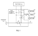
- local management units (101) are used to switch on and off the solar module (102) periodically to improve the energy production performance of the photovoltaic systems connected, at least in part, in series.
- a management unit (101) is local to the solar module (102) and can be used to periodically couple the solar module (102) to the serial power bus (103) via the switch Q1 (106), to improve the total power output for the string of solar modules connected to the serial power bus in series.
- the local management unit (LMU) (101) may include a solar module controller to control the operation of the solar module (102) and/or a link module unit to provide connectivity to the serial power bus (103) for energy delivery and/or for data communications.
- LMU local management unit
- the command to control the operation of the switch Q1 (106) is sent to the local management unit (101) over the photovoltaic (PV) string bus (power line) (103).
- PV photovoltaic
- separate network connections can be used to transmit the data and/or commands to/from the local management unit (101).
- the inputs (104a, 104b, 104c) to the local management unit (101) are illustrated separately. However, the inputs (104a, 104b, 104c) are not necessarily communicated to local management unit (101) via separate connections. In one embodiment, the inputs are received in the local management unit via the serial power bus (103).
- the solar module (102) is connected in parallel to the capacitor C1 (105) of the local management unit (101).
- the diode D1 (107) of the local management unit (101) is connected in series in the serial power bus (103) which may or may not be part of an overall mesh configuration of solar modules.
- the switch Q1 (106) of the local management unit can selectively connect or disconnect the solar module (102) and the capacitor C1 (105) from a parallel connection with the diode D1 (107) and thus connect or disconnect the solar module (102) from the serial power bus (103).
- a controller (109) of the local management unit (101) controls the operation of the switch (106) according to the parameters, such as duty cycle (104a), phase (104b) and synchronization pulse (104c).
- the controller (109) receives the parameters (104a, 104b, 104c) from a remote management unit via the serial power bus (103) or a separate data communication connection (e.g., a separate data bus or a wireless connection).
- the controller (109) may communicate with other local management units connected on the serial power bus (103) to obtain operating parameters of the solar modules attached to the serial power bus (103) and thus compute the parameters (e.g., 104a and 104b) based on the received operating parameters.
- the controller (109) may determine the parameter (e.g., 104a and 104b) based on the operating parameters of the solar module (102) and/or measurements obtained by the controller (109), without communicating with other local management units of other solar modules, or a remote system management unit.
- the parameter e.g., 104a and 104b
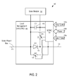
- a system (100) has a local management unit (101) coupled to the solar module (102).
- the local management unit (101) is connected between the solar module (102) and the string bus (103) to improve the total power output for the whole string on the serial power bus (103).
- Commands to the local management unit (101) can be sent over the photovoltaic (PV) string bus (power line) (103).
- PV photovoltaic
- the inputs (104a, 104b, 104c) to the controller (109) of the local management unit (101) were drawn separately, which does not necessarily indicate that the inputs (104a, 104b, 104c) are provided via separate connections and/or from outside the local management unit (101).
- the controller (109) may compute the parameters (104a, 104b, 104c) based on measurements obtained at the local management unit (101), with or without data communications over the serial power bus (103) (or a separate data communication connection with other management units).
- the local management unit (101) is connected in one side to the solar module (102) in parallel and on the other side in series to a string of other modules, which may or may not be part of an overall mesh configuration.
- the local management unit (101) may receive, among others, three inputs or types of input data, including a) requested duty cycle (104a), which can be expressed as a percentage (e.g., from 0 to 100%) of time the solar module (102) is to be connected to the serial power bus (103) via the switch Q1 (106), b) a phase shift (104b) in degrees (e.g., from 0 degree to 180 degree) and c) a timing or synchronization pulse (104c).
- a requested duty cycle 104a
- a phase shift 104b
- degrees e.g., from 0 degree to 180 degree
- a timing or synchronization pulse 104c
- These inputs can be supplied as discrete signals, or can be supplied as data on a network, or composite signals sent through the power lines or wirelessly, and in yet other cases, as a combination of any of these input types.
- the local management unit (101) periodically connects and disconnects the solar module (102) to and from the string that forms the serial power bus (103).
- the duty cycle (104a) and the phase (104b) of the operation of the switch Q1 (106) can be computed in a number of ways to improve the performance of the system, which will be discussed further below.
- the local management unit (101) includes a capacitor C 1 (105) and a switch Q1 (106), as well as a diode D1 (107).
- the diode D1 (107) is supplemented with an additional switch Q2 (108), which acts as a synchronous rectifier to increase efficiency.
- the additional switch Q2 (108) is open (turned off) when the switch Q1 (106) is closed (turned on) to attach the solar module (102) (and the capacitor C1 (105)) to the serial power bus (103).
- a filter (not shown), including a serial coil and a parallel capacitor, is also used.
- the filter may be placed at the local management unit or placed just before the fuse box or inverter, or be part of either one of those.
- the controller (109) is used to process the input signals (e.g., 104a, 104b, 104c) and drive the switches Q1 (106) and Q2 (108).
- the controller (109) is a small single chip micro controller (SCMC).
- SCMC small single chip micro controller
- the controller (109) may be implemented using Application-Specific Integrated Circuit (ASIC) or Field-Programmablc Gate Array (FPGA).
- ASIC Application-Specific Integrated Circuit
- FPGA Field-Programmablc Gate Array
- the controller (109) can even be implemented in discrete, functionally equivalent circuitry, or in other cases a combination of SCMC and discrete circuitry.
- the controller (109) is coupled to the solar module (102) in parallel to obtain power for processing; and the controller (109) is coupled to the serial power bus (103) to obtain signals transmitted from other management units coupled to the serial power bus (103).
- the local management unit (10 1) may lower the voltage reflected to the string bus (103) (e.g., a lower average voltage contributed to the string bus) and can cause the current reflected to the string bus (103) to be higher, nearer the level it would be if the module was not weak, generating a higher total power output.
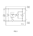
- the local management unit (101) provides two connectors (112 and 114) for serial connections with other local management unit (101) to form a serial power bus (103).
- the controller (109) controls the states of the switches Q1 (106) and Q2 (108).
- the controller (109) is connected (not shown in Figure 3 ) to the panel voltage to obtain the power for controlling the switches Q1 (106) and Q2 (108). In one embodiment, the controller (109) is further connected (not shown in Figure 3 ) to at least one of the connectors to transmit and/or receive information from the string. In one embodiment, the controller (109) includes sensors (not shown in Figure 3 ) to measure operating parameters of the solar panel, such as panel voltage, panel current, temperature, light intensity, etc.
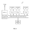
- FIG 4 illustrates a photovoltaic system (200) according to one embodiment.
- the photovoltaic system 200 is built from a few components, including photovoltaic modules (201a, 201b, ..., 201n), local management unit units (202a, 202b, ..., 202n), an inverter (203), and a system management unit (204).
- the system management unit (204) is part of the inverter (203), the combiner box (206), a local management unit, or a stand-alone unit.
- the solar modules (201a, 201b, ..., 201n) are connected in parallel to the local management unit units (202a, 202b, ..., 202n) respectively, which are connected in series to form a string bus (205), which eventually is connected to an inverter (203) and the management unit (204).
- the string bus (205) can be connected to the inverter (203) directly or as part of a mesh network or combiner boxes or fuse boxes (not shown).
- An isolated local management unit can be used as a combiner box (206) to adjust all voltages before connecting to the inverter (206); or, a single or multi-string inverter can be used.
- the management unit (204) may assign a different phase for each of the local management units (202a, 202b, ..., 202n). In one embodiment, at any given time, a maximum of a predetermined number of solar modules (e.g., one single solar module) are disconnected from the string bus (205).
- the local management units can have the signal inputs, including but not limited to duty cycle (104a), phase (104b) and synchronization pulse (104c) (e.g., to keep the local management units synchronized).
- the phase (104b) and the synchronization pulse (104c) are used to further improve performance, but the local management unit (101) can work without them.
- the local management unit may provide output signals.
- the local management unit (101) may measure current and voltage at the module side and optionally measure current and voltage in the string side.
- the local management unit (101) may provide other suitable signals, including but not limited to measurements of light, temperature (both ambient and module), etc.
- the output signals from the local management unit (101) arc transmitted over the power line (e.g., via power line communication (PLC)), or transmitted wirelessly.
- PLC power line communication
- the system management unit (204) receives sensor inputs from light sensor(s), temperature sensor(s), one or more each for ambient, solar module or both, to control the photovoltaic system (200).
- the signals may also include synchronization signals.
- a management unit can send synchronization signals periodically to set the timing values, etc.
- the local management unit can be a very non-expensive and reliable device that can easily increase the throughput of a photovoltaic solar system by a few (e.g., signal or low double digits) percentage points.
- These varied controls also allow installers using this kind of system to control the VOC (open circuit voltage) by, for example by shutting off some or all modules.
- VOC open circuit voltage
- a few modules can be disconnected from a string if a string is getting to the regulatory voltage limit, thus more modules can be installed in a string.
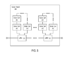
- local management units can also be used within the solar panel to control the connection of solar cells attached to strings of cells within the solar panel.
- FIG. 5 illustrates a solar panel according to one embodiment.
- the solar panel (300) has a few strings of solar cells (e.g., three solar cell strings per module).
- a local management unit (101) can be applied to a group of cells (301) within a string of an individual solar panel (300), or in some cases to each cell (301) in a solar panel (300).
- a group of solar cells (301) that are attached to a local management unit (101) may be connected to each other in series, in parallel, or in a mesh configure.
- a number of local management units (101) connect the groups of the solar cells (301) in a string to provide output for the solar panel (300).
- Some embodiments of the disclosure includes methods to determine the duty cycles and/or phases for local management units connected to a string or mesh of solar modules.
- the duty cycle of all local management units in a string or mesh can be changed, to increase or decrease the string voltage.
- the duty cycles may be adjusted to avoid exceeding the maximum voltage allowed.
- the maximum voltage may be limited by the combiner box (206), the inverter (203), or any other load connected to the string bus (205), or limited by any regulations applicable to that system.
- the duty cycles are adjusted to align the voltage of multiple strings.
- the duty cycle of one local management unit (101) in a string can be changed to cause higher current in that local management unit (101) and overall higher power harvesting.
- the duty cycles are computed for the solar modules that are connected to a string via the corresponding local management units.
- the duty cycles can be calculated based on the measured current and voltages of the solar modules and/or the temperatures.
- the duty cycles can be further fine tuned and/or re-adjusted to changes, such as shifting shading etc., one step a time, to improve power performance (e.g., to increase power output, to increase voltage, to increase current, etc.).
- target voltages are computed for the solar modules, and the duty cycles are adjusted to drive the module voltage towards the target voltages.
- the methods to compute the duty cycles of the solar modules can also be used to compute the duty cycles of the groups of solar cells within a solar module.
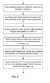
- Figures 6 - 8 show methods to improve performance of a photovoltaic system according to some embodiments.
- At least one operating parameter of a solar energy production unit coupled to a string via a management unit is received (401) and used to identify (403) a duty cycle for the management unit to connect the solar energy production unit to string.
- the solar energy production unit may be a solar module, a group of solar cells within a solar module, or a single solar cell in a string in a solar module.
- the duty cycle is adjusted (405) to optimize the performance of the solar energy production unit and/or the string.
- the duty cycle can be adjusted to increase the current in the string and/or the solar energy production unit, to increase the output power of the string and/or the solar energy production unit, to increase the voltage of the solar energy production unit, etc.
- the operating voltages of a plurality of solar panels connected in series are received (421) and used to identify (423) a second solar panel having the highest operating voltage (highest output power) in the string.
- a duty cycle of a first solar panel is computed (425) based on a ratio in operating voltage between the first and second solar panels.
- the duty cycle can be computed based on a ratio in output power between the first and second solar panels.
- the duty cycle can be computed based on a ratio between the first and second solar panels in estimated/computed maximum power point voltage.
- the duty cycle can be computed based on a ratio between the first and second solar panels in estimated/computed maximum power point power.
- the duty cycle of the first solar panel is adjusted (427) to improve the performance of the first solar energy production unit and/or the string, until a decrease in the operating voltage of the second solar panel is detected.
- the duty cycle of the first solar panel can be adjusted to increase the total output power of the string, to increase the current of the string, to increase the current of the first solar panel, to drive the voltage of the first solar panel towards a target voltage, such as its maximum power point voltage estimated based on its current operating parameters, such as temperature or a voltage calculated using its estimated maximum power point voltage.
- the duty cycle of the second solar panel is optionally decreased (431) to increase the operating voltage of the second solar panel.
- the strongest solar panel or strong panels within a threshold from the strongest panel
- is not switched off line e.g., to have a predetermined duty cycle of 100%.
- the duty cycle of the second solar panel is repeatedly decreased (429) until it is determined (431) that the decrease (429) in the duty cycle of the second solar panel cannot increase the voltage of the second solar panel.
- operating parameters of a plurality of solar panels connected in a string are received (441) and used to identify (443) a first maximum power point voltage of a first solar panel.
- a second solar panel having the highest operating voltage (or output power) in the string is identified.
- a second maximum power point voltage of the second solar panel is identified (447) based on the received operating parameters and used to compute (449) a target voltage for the first solar energy production unit.
- the target voltage is a function of the first and second maximum power point voltages and the highest operating voltage identified (445) in the second solar panel in the string.
- the duty cycle of the first solar energy production unit is adjusted to drive the operating voltage of the first solar panel towards the target voltage.
- the target voltage may be the set as the first maximum power point voltage of the first solar panel.
- a same factor is applied to all modules in that string. For example, in a case of a first module A1 that is producing only 80%, and the voltage of the whole string needs to be 5% lower, the duty cycle of A1 is 80% multiplied the duty cycle applied to the whole string (which is Y in this example) so module A1 then has Y ⁇ 0.8 as duty cycle.
- system management unit (204) and/or the local management units are used solely or in combination to determine the parameters to control the operations of the switches.
- a system management unit (204) is the "brain" of the system, which decides on the duty cycle and phase parameters.
- each local management unit broadcasts information to the other local management units on the string to allow the individual local management units to decide their own duty cycle and phase parameters.
- a local management unit may instruct one or more other local management units to adjust duty cycle and phase parameters.
- the local management units on a string bus (205) may elect one local management unit to compute the duty cycle and phase parameters for other local management units on the string.
- the system management unit (204) may determine one or more global parameters (e.g., a global duty cycle, the maximum power on the string, the maximum voltage on the string, etc.), based on which individual local management units adjust their own duty cycles.
- one or more global parameters e.g., a global duty cycle, the maximum power on the string, the maximum voltage on the string, etc.
- a local management unit may determine its own duty cycles without relying upon communicating with other management units. For example, the local management unit may adj ust its duty cycle for connecting its solar module to the string to operate the solar module at the maximum power point.
- module voltage are measured by the local management units in the same string at substantially/approximately the same time and used to identify the strongest solar module.
- a strongest solar module provides the most power in the string. Since the modules are connected in series, the solar module having the highest module voltage in the string can be identified as the strongest solar module.
- the operating voltage and current of the solar module arc measured to determine the power of the solar module.
- the duty cycle for each module can be computed as a function of a ratio between the module voltage V of the module and the highest module voltage V m .
- the system management (204) may identify the highest module voltage from the module voltages received from the local management units (202a, 202b, ..., 202n), and compute the duty cycles for the corresponding local management units (202a, 202b, ..., 202n).
- the local management units may report their module voltages on the string bus (205) to allow individual local management units (202a, 202b, ..., 202n) to identify the highest module voltage and compute the duty cycles, without relying upon the system management unit (204).
- one of the local management units may identify the highest module voltage and/or compute the duty cycles for the other local management units (202a, 202b, ..., 202n).
- the duty cycles are determined and/or adjusted periodically.
- the duty cycles for the solar modules on the string are set based on the module voltage ratio relative to the highest module voltage in the string, the duty cycles can be fine tuned to increase the power performance.
- the duty cycles can be fine tuned one step a time, until a decrease of voltage of the module with the highest power is detected. In response to the detected decrease, the last change that caused the decrease can be reversed (undone).
- the fine tuning of the duty cycles can be used to reach the peak performance point (e.g., for maximum power point tracking).
- the duty cycles of the solar modules on the string are adjusted until the module with the highest power in the string decrease its voltage. Since decreasing the duty cycle of a solar module decreases the time period the module is connected to the string and thus increases its voltage, the duty cycle of the module with the highest power in the string can be decreased to increase its voltage, in response to the decrease in its voltage caused by the adjustment to the duty cycles of other solar modules on the string. For example, the duty cycle of the module with the highest power in the string can be decreased until its voltage is maximized.
- the local management unit measures module and ambient temperatures for some methods to determine the duty cycles.
- the operating parameters measured at the local management units e.g., 202a, 202b, ..., 202n
- module temperature can be used compute the estimated voltages of the solar modules at their maximum power points.
- a formula presented by Nalin K. Gautam and N.D. Kaushika in "An efficient algorithm to simulate the electrical performance of solar photovoltaic arrays", Energy, Volume 27, Issue 4, April 2002, pages 347-261 can be used to compute the voltage V mp of a solar module at the maximum power point.
- Other formulae can also be used.
- the duty cycle of the solar module connected to a string can be adjusted to drive the module voltage to the computed/estimated maximum power point voltage V mp , since decreasing the duty cycle of a solar module normally increases its voltage.
- a local management unit may adjust the duty cycle of the solar module connected to the local management unit to change the module voltage to the computed/estimated maximum power point voltage V mp , without having to communicating with other management units.
- a local management unit may adjust the duty cycle of the solar module connected to the local management unit to perform maximum power point tracking.
- the duty cycle for each module on a string can be computed as a function of a ratio between the maximum power point voltage V mp of the module and the maximum power point voltage V mpm of the strongest module.
- the duty cycle can be periodically updated, based on the current operating parameters measured, and/or fine tuned until a decrease in the voltage of the strongest module is detected.
- a target voltage for each module on the string can be computed as a function of a ratio between the maximum power point voltage V mp of the module and the maximum power point voltage V mpm of the strongest module.
- the target voltage for a module can be computed as V m ⁇ V mp /V mpm , where V m is the measured voltage of the strongest module.
- the duty cycle of the module can be changed to drive the module voltage of the module towards the target voltage.
- the duty cycle for each module on a string can be computed as a function of a ratio between the maximum power point power P mp of the module and the maximum power point power P mpm of the strongest module.
- the duty cycle can be periodically updated, based on the current operating parameters measured, and/or fine tuned until a decrease in the voltage of the strongest module is detected, since decreasing the duty cycle normally increases the module voltage.
- a target voltage for each module on the string can be computed as a function of a ratio between the maximum power point power P mp of the module and the maximum power point power P mpm of the strongest module.
- the target voltage for a module can be computed as V m ⁇ P mp /P mpm , where V m is the measured voltage of the strongest module.
- the duty cycle of the module can be changed to drive the module voltage of the module towards the target voltage, since decreasing the duty cycle normally increases the module voltage.
- the duty cycle for each local management unit is changed to increase the current of the solar module attached to the local management unit (e.g., based on the measurement of the votlage and current of the solar module), until the maximum current is achieved.
- This method assumes that string maximum power can be achieved with some accuracy by driving each local management unit to maximum current.
- the voltages and currents of the solar modules are measured for tuning the duty cycles for maximum power point tracking for the string. The measurements of the voltages and currents of the solar modules also enable the local management units to additionally serve as a module level monitoring system.
- the duty cycles can be adjusted by the system management unit (e.g., 204) based on the measurements reported by the local management units (e.g., 202a, 202b, ..., 202n), or adjusted directly by the corresponding local management units (e.g., 202a, 202b, ..., 202n).
- the maximum power point tracking operation by the inverter (203) is frozen (temporarily stopped).
- Light intensity at the solar modules is monitored for changes.
- the voltage and current of the solar modules are measured for the determination of thc duty cycles. Then normal operation resumes (c.g., unfreezing of maximum power point tracking operation).
- a predetermined threshold is used to select the weak modules to apply duty cycles. For example, in one embodiment, when a module produces power less than a predetermine percent of highest power P m , a duty cycle is calculated and applied to the solar module. If the module is above the threshold, the module is not disconnected (and thus having a duty cycle of 100%).
- the threshold may be based on the power, or based on the module voltage.
- the system management unit (204) finds the duty cycles for the local management units (202a, 202b, ..., 202n) and transmits data and/or signals representing the duty cycles to the local management units (202a, 202b, ..., 202n) via wires or wireless connections.
- the local management units (202a, 202b, ..., 202n) may communicate with each other to obtain the parameters to calculate the duty cycles.
- the system management unit (204) knows all the different duty cycles indicated for the local management units (202a, 202b, ..., 202n).
- the system management unit (204) sends the appropriate data/signal to the appropriate local management units (202a, 202b, ..., 202n), and then the system management unit (204) calculates the total power of the string and corrects the duty cycle to produce maximum power.
- the duty cycles for the local management units (202a, 202b, ..., 202n) may be saved in a database and serve as a starting point for the corresponding local management units (202a, 202b, ..., 202n) at the same time of day on the next day.
- a local management may store the duty cycle in its memory for the next day.
- the stored duty cycles can be used when there is a fixed shade on the modules, such as a chimney, a tree, etc., which will be the same shade on any day at the same time.
- historical data may not be saved, but may be recalculated from scratch on each run, for example every 30 minutes.
- the light intensity at the solar modules is monitored for changes.
- the duty cycles are calculated when the light intensity does not change significantly. If there are changes in sun light radiation at the solar modules, the system will wait until the environment stabilizes before applying or adjusting the duty cycles.
- the system management unit (204) can communicate with the inverter as well.
- the inverter may stop maximum power point tracking. In such a situation, the inverter can be set up for its load, instead of tracking for maximum power point.
- the system management unit (204) and the local management units are used to set the operating parameters and balance the string.
Landscapes
- Engineering & Computer Science (AREA)
- Power Engineering (AREA)
- Control Of Electrical Variables (AREA)
- Photovoltaic Devices (AREA)
Applications Claiming Priority (4)
| Application Number | Priority Date | Filing Date | Title |
|---|---|---|---|
| US20027908P | 2008-11-26 | 2008-11-26 | |
| US20060108P | 2008-12-02 | 2008-12-02 | |
| US12/411,317 US7602080B1 (en) | 2008-11-26 | 2009-03-25 | Systems and methods to balance solar panels in a multi-panel system |
| EP09829487A EP2223347A4 (en) | 2008-11-26 | 2009-06-18 | SYSTEMS AND METHOD FOR THE ADJUSTMENT OF SOLAR CELLS IN A MULTI-CELL SYSTEM |
Related Parent Applications (1)
| Application Number | Title | Priority Date | Filing Date |
|---|---|---|---|
| EP09829487A Division EP2223347A4 (en) | 2008-11-26 | 2009-06-18 | SYSTEMS AND METHOD FOR THE ADJUSTMENT OF SOLAR CELLS IN A MULTI-CELL SYSTEM |
Publications (1)
| Publication Number | Publication Date |
|---|---|
| EP2685510A1 true EP2685510A1 (en) | 2014-01-15 |
Family
ID=41137989
Family Applications (2)
| Application Number | Title | Priority Date | Filing Date |
|---|---|---|---|
| EP20130187906 Withdrawn EP2685510A1 (en) | 2008-11-26 | 2009-06-18 | Systems And Methods To Balance Solar Panels In A Multi-Panel System |
| EP09829487A Ceased EP2223347A4 (en) | 2008-11-26 | 2009-06-18 | SYSTEMS AND METHOD FOR THE ADJUSTMENT OF SOLAR CELLS IN A MULTI-CELL SYSTEM |
Family Applications After (1)
| Application Number | Title | Priority Date | Filing Date |
|---|---|---|---|
| EP09829487A Ceased EP2223347A4 (en) | 2008-11-26 | 2009-06-18 | SYSTEMS AND METHOD FOR THE ADJUSTMENT OF SOLAR CELLS IN A MULTI-CELL SYSTEM |
Country Status (8)
| Country | Link |
|---|---|
| US (5) | US7602080B1 (ja) |
| EP (2) | EP2685510A1 (ja) |
| JP (1) | JP5430669B2 (ja) |
| KR (1) | KR20110086666A (ja) |
| CN (1) | CN101849293B (ja) |
| AU (1) | AU2009278056A1 (ja) |
| IL (1) | IL204103A0 (ja) |
| WO (1) | WO2010062410A1 (ja) |
Cited By (1)
| Publication number | Priority date | Publication date | Assignee | Title |
|---|---|---|---|---|
| CN106251746A (zh) * | 2016-08-22 | 2016-12-21 | 朱凌 | 一种便携式光伏电站模拟仪运行控制系统 |
Families Citing this family (122)
| Publication number | Priority date | Publication date | Assignee | Title |
|---|---|---|---|---|
| US7839022B2 (en) | 2004-07-13 | 2010-11-23 | Tigo Energy, Inc. | Device for distributed maximum power tracking for solar arrays |
| US10693415B2 (en) | 2007-12-05 | 2020-06-23 | Solaredge Technologies Ltd. | Testing of a photovoltaic panel |
| US11881814B2 (en) | 2005-12-05 | 2024-01-23 | Solaredge Technologies Ltd. | Testing of a photovoltaic panel |
| US8319483B2 (en) | 2007-08-06 | 2012-11-27 | Solaredge Technologies Ltd. | Digital average input current control in power converter |
| US11855231B2 (en) | 2006-12-06 | 2023-12-26 | Solaredge Technologies Ltd. | Distributed power harvesting systems using DC power sources |
| US9112379B2 (en) | 2006-12-06 | 2015-08-18 | Solaredge Technologies Ltd. | Pairing of components in a direct current distributed power generation system |
| US9130401B2 (en) | 2006-12-06 | 2015-09-08 | Solaredge Technologies Ltd. | Distributed power harvesting systems using DC power sources |
| WO2009073868A1 (en) | 2007-12-05 | 2009-06-11 | Solaredge, Ltd. | Safety mechanisms, wake up and shutdown methods in distributed power installations |
| US11735910B2 (en) | 2006-12-06 | 2023-08-22 | Solaredge Technologies Ltd. | Distributed power system using direct current power sources |
| US8618692B2 (en) | 2007-12-04 | 2013-12-31 | Solaredge Technologies Ltd. | Distributed power system using direct current power sources |
| US8473250B2 (en) | 2006-12-06 | 2013-06-25 | Solaredge, Ltd. | Monitoring of distributed power harvesting systems using DC power sources |
| US11888387B2 (en) | 2006-12-06 | 2024-01-30 | Solaredge Technologies Ltd. | Safety mechanisms, wake up and shutdown methods in distributed power installations |
| US11687112B2 (en) | 2006-12-06 | 2023-06-27 | Solaredge Technologies Ltd. | Distributed power harvesting systems using DC power sources |
| US8319471B2 (en) | 2006-12-06 | 2012-11-27 | Solaredge, Ltd. | Battery power delivery module |
| US8384243B2 (en) | 2007-12-04 | 2013-02-26 | Solaredge Technologies Ltd. | Distributed power harvesting systems using DC power sources |
| US11309832B2 (en) | 2006-12-06 | 2022-04-19 | Solaredge Technologies Ltd. | Distributed power harvesting systems using DC power sources |
| US8947194B2 (en) | 2009-05-26 | 2015-02-03 | Solaredge Technologies Ltd. | Theft detection and prevention in a power generation system |
| US11728768B2 (en) | 2006-12-06 | 2023-08-15 | Solaredge Technologies Ltd. | Pairing of components in a direct current distributed power generation system |
| US8816535B2 (en) | 2007-10-10 | 2014-08-26 | Solaredge Technologies, Ltd. | System and method for protection during inverter shutdown in distributed power installations |
| US11296650B2 (en) | 2006-12-06 | 2022-04-05 | Solaredge Technologies Ltd. | System and method for protection during inverter shutdown in distributed power installations |
| US8013472B2 (en) | 2006-12-06 | 2011-09-06 | Solaredge, Ltd. | Method for distributed power harvesting using DC power sources |
| US9088178B2 (en) | 2006-12-06 | 2015-07-21 | Solaredge Technologies Ltd | Distributed power harvesting systems using DC power sources |
| US11569659B2 (en) | 2006-12-06 | 2023-01-31 | Solaredge Technologies Ltd. | Distributed power harvesting systems using DC power sources |
| US8963369B2 (en) | 2007-12-04 | 2015-02-24 | Solaredge Technologies Ltd. | Distributed power harvesting systems using DC power sources |
| US9407093B2 (en) | 2007-08-22 | 2016-08-02 | Maxout Renewables, Inc. | Method for balancing circuit voltage |
| WO2009055474A1 (en) | 2007-10-23 | 2009-04-30 | And, Llc | High reliability power systems and solar power converters |
| CA2737134C (en) | 2007-10-15 | 2017-10-10 | Ampt, Llc | Systems for highly efficient solar power |
| US8933321B2 (en) | 2009-02-05 | 2015-01-13 | Tigo Energy, Inc. | Systems and methods for an enhanced watchdog in solar module installations |
| US8823218B2 (en) | 2007-11-02 | 2014-09-02 | Tigo Energy, Inc. | System and method for enhanced watch dog in solar panel installations |
| US7602080B1 (en) | 2008-11-26 | 2009-10-13 | Tigo Energy, Inc. | Systems and methods to balance solar panels in a multi-panel system |
| US11228278B2 (en) | 2007-11-02 | 2022-01-18 | Tigo Energy, Inc. | System and method for enhanced watch dog in solar panel installations |
| WO2009072075A2 (en) | 2007-12-05 | 2009-06-11 | Solaredge Technologies Ltd. | Photovoltaic system power tracking method |
| EP2232690B1 (en) | 2007-12-05 | 2016-08-31 | Solaredge Technologies Ltd. | Parallel connected inverters |
| EP2225778B1 (en) | 2007-12-05 | 2019-06-26 | Solaredge Technologies Ltd. | Testing of a photovoltaic panel |
| US11264947B2 (en) | 2007-12-05 | 2022-03-01 | Solaredge Technologies Ltd. | Testing of a photovoltaic panel |
| US8049523B2 (en) | 2007-12-05 | 2011-11-01 | Solaredge Technologies Ltd. | Current sensing on a MOSFET |
| EP2722979B1 (en) | 2008-03-24 | 2022-11-30 | Solaredge Technologies Ltd. | Switch mode converter including auxiliary commutation circuit for achieving zero current switching |
| WO2009136358A1 (en) | 2008-05-05 | 2009-11-12 | Solaredge Technologies Ltd. | Direct current power combiner |
| US8273979B2 (en) * | 2008-10-15 | 2012-09-25 | Xandex, Inc. | Time averaged modulated diode apparatus for photovoltaic application |
| US8860241B2 (en) * | 2008-11-26 | 2014-10-14 | Tigo Energy, Inc. | Systems and methods for using a power converter for transmission of data over the power feed |
| US9401439B2 (en) | 2009-03-25 | 2016-07-26 | Tigo Energy, Inc. | Enhanced systems and methods for using a power converter for balancing modules in single-string and multi-string configurations |
| SG175717A1 (en) | 2009-04-17 | 2011-12-29 | Ampt Llc | Methods and apparatus for adaptive operation of solar power systems |
| CN104135218B (zh) | 2009-05-19 | 2018-02-13 | 最大输出可再生能源公司 | 电路电压平衡方法、电路校正方法及主逆变器校正方法 |
| US8102074B2 (en) | 2009-07-30 | 2012-01-24 | Tigo Energy, Inc. | Systems and method for limiting maximum voltage in solar photovoltaic power generation systems |
| US8314375B2 (en) | 2009-08-21 | 2012-11-20 | Tigo Energy, Inc. | System and method for local string management unit |
| WO2011049985A1 (en) | 2009-10-19 | 2011-04-28 | Ampt, Llc | Novel solar panel string converter topology |
| US8710699B2 (en) | 2009-12-01 | 2014-04-29 | Solaredge Technologies Ltd. | Dual use photovoltaic system |
| US8773236B2 (en) * | 2009-12-29 | 2014-07-08 | Tigo Energy, Inc. | Systems and methods for a communication protocol between a local controller and a master controller |
| US8271599B2 (en) | 2010-01-08 | 2012-09-18 | Tigo Energy, Inc. | Systems and methods for an identification protocol between a local controller and a master controller in a photovoltaic power generation system |
| FR2955209B1 (fr) * | 2010-01-12 | 2015-06-05 | Arnaud Thierry | Systeme de gestion et de commande de panneaux photovoltaiques |
| US8766696B2 (en) | 2010-01-27 | 2014-07-01 | Solaredge Technologies Ltd. | Fast voltage level shifter circuit |
| DE102010054354B4 (de) * | 2010-12-13 | 2024-07-25 | Ingmar Kruse | Verfahren zur Abschaltung einer Photovoltaikanlage sowie Photovoltaikanlage |
| US9007210B2 (en) * | 2010-04-22 | 2015-04-14 | Tigo Energy, Inc. | Enhanced system and method for theft prevention in a solar power array during nonoperative periods |
| WO2011142406A1 (ja) * | 2010-05-12 | 2011-11-17 | オムロン株式会社 | 電圧変換装置および電圧変換方法、電力調整装置および電力調整方法、太陽光発電システム、並びに管理装置 |
| US20110316343A1 (en) * | 2010-06-25 | 2011-12-29 | International Business Machines Corporation | Photovoltaic module with integrated diagnostics |
| US8466706B2 (en) | 2010-08-17 | 2013-06-18 | Schneider Electric USA, Inc. | Solar combiner with integrated string current monitoring |
| US10347775B2 (en) * | 2010-08-30 | 2019-07-09 | Shoals Technologies Group, Llc | Solar array recombiner box with wireless monitoring capability |
| WO2012038828A1 (en) * | 2010-09-23 | 2012-03-29 | Hybridine Power Electronics Inc. | A method and system for optimizing power generated from a photovoltaic system |
| DE102010047378A1 (de) | 2010-10-05 | 2012-04-05 | Hpf Gmbh | Verfahren und Anordnung zur Überwachung von Betriebs-Parametern einer Gleichstromquelle |
| GB2485527B (en) | 2010-11-09 | 2012-12-19 | Solaredge Technologies Ltd | Arc detection and prevention in a power generation system |
| US10673229B2 (en) | 2010-11-09 | 2020-06-02 | Solaredge Technologies Ltd. | Arc detection and prevention in a power generation system |
| US10230310B2 (en) | 2016-04-05 | 2019-03-12 | Solaredge Technologies Ltd | Safety switch for photovoltaic systems |
| US10673222B2 (en) | 2010-11-09 | 2020-06-02 | Solaredge Technologies Ltd. | Arc detection and prevention in a power generation system |
| GB2486408A (en) | 2010-12-09 | 2012-06-20 | Solaredge Technologies Ltd | Disconnection of a string carrying direct current |
| GB2496140B (en) | 2011-11-01 | 2016-05-04 | Solarcity Corp | Photovoltaic power conditioning units |
| US8547669B2 (en) | 2011-01-12 | 2013-10-01 | Schneider Electric USA, Inc. | Arc fault mitigation for photovoltaic systems |
| GB2483317B (en) | 2011-01-12 | 2012-08-22 | Solaredge Technologies Ltd | Serially connected inverters |
| GB2485423B (en) | 2011-01-18 | 2014-06-04 | Enecsys Ltd | Solar photovoltaic systems |
| CN103477524B (zh) * | 2011-03-30 | 2015-08-12 | 三洋电机株式会社 | 集电箱 |
| DE102011079074A1 (de) * | 2011-07-13 | 2013-01-17 | Robert Bosch Gmbh | Steuersystem für eine spannungssichere Photovoltaikanlage |
| US9431825B2 (en) | 2011-07-28 | 2016-08-30 | Tigo Energy, Inc. | Systems and methods to reduce the number and cost of management units of distributed power generators |
| US9368965B2 (en) * | 2011-07-28 | 2016-06-14 | Tigo Energy, Inc. | Enhanced system and method for string-balancing |
| US9142965B2 (en) * | 2011-07-28 | 2015-09-22 | Tigo Energy, Inc. | Systems and methods to combine strings of solar panels |
| CN102916614A (zh) * | 2011-08-03 | 2013-02-06 | 台达电子企业管理(上海)有限公司 | 具有电压平衡器的光伏系统及光伏模块 |
| US8570005B2 (en) | 2011-09-12 | 2013-10-29 | Solaredge Technologies Ltd. | Direct current link circuit |
| GB2496139B (en) | 2011-11-01 | 2016-05-04 | Solarcity Corp | Photovoltaic power conditioning units |
| US9214893B2 (en) * | 2011-11-10 | 2015-12-15 | Veris Industries, Llc | String monitor |
| GB2498365A (en) | 2012-01-11 | 2013-07-17 | Solaredge Technologies Ltd | Photovoltaic module |
| US9853565B2 (en) | 2012-01-30 | 2017-12-26 | Solaredge Technologies Ltd. | Maximized power in a photovoltaic distributed power system |
| GB2498790A (en) | 2012-01-30 | 2013-07-31 | Solaredge Technologies Ltd | Maximising power in a photovoltaic distributed power system |
| GB2498791A (en) | 2012-01-30 | 2013-07-31 | Solaredge Technologies Ltd | Photovoltaic panel circuitry |
| WO2013121589A1 (ja) * | 2012-02-17 | 2013-08-22 | 三菱電機株式会社 | 電力変換装置、及び電力変換システム |
| GB2499991A (en) | 2012-03-05 | 2013-09-11 | Solaredge Technologies Ltd | DC link circuit for photovoltaic array |
| EP2859650B1 (en) | 2012-05-25 | 2017-02-15 | Solaredge Technologies Ltd. | Circuit for interconnected direct current power sources |
| US10115841B2 (en) | 2012-06-04 | 2018-10-30 | Solaredge Technologies Ltd. | Integrated photovoltaic panel circuitry |
| TWI461882B (zh) * | 2012-09-18 | 2014-11-21 | Univ Nat Taiwan | 太陽能模組系統之多點直接預測最大功率點追蹤方法及太陽能模組陣列之控制裝置 |
| US9548619B2 (en) | 2013-03-14 | 2017-01-17 | Solaredge Technologies Ltd. | Method and apparatus for storing and depleting energy |
| US9941813B2 (en) | 2013-03-14 | 2018-04-10 | Solaredge Technologies Ltd. | High frequency multi-level inverter |
| WO2014149775A1 (en) * | 2013-03-15 | 2014-09-25 | Maxout Renewables, Inc. | Architecture for power plant comprising clusters of power-generation devices |
| US9397497B2 (en) | 2013-03-15 | 2016-07-19 | Ampt, Llc | High efficiency interleaved solar power supply system |
| EP4318001A3 (en) | 2013-03-15 | 2024-05-01 | Solaredge Technologies Ltd. | Bypass mechanism |
| US9543455B2 (en) | 2013-05-01 | 2017-01-10 | Tigo Energy, Inc. | System and method for low-cost, high-efficiency solar panel power feed |
| JP3189106U (ja) | 2013-12-12 | 2014-02-20 | ティー・エス・ビー株式会社 | 太陽光発電システム |
| JP6246616B2 (ja) * | 2014-02-25 | 2017-12-13 | 太陽誘電株式会社 | コンバータ及び当該コンバータを含む太陽光発電システム |
| US9318974B2 (en) | 2014-03-26 | 2016-04-19 | Solaredge Technologies Ltd. | Multi-level inverter with flying capacitor topology |
| US10218307B2 (en) | 2014-12-02 | 2019-02-26 | Tigo Energy, Inc. | Solar panel junction boxes having integrated function modules |
| WO2017011528A1 (en) * | 2015-07-13 | 2017-01-19 | Maxim Intergrated Products, Inc. | Systems and methods for dc power line communication in a photovoltaic system |
| US10374424B2 (en) * | 2015-08-18 | 2019-08-06 | Argentum Electronics, Inc. | Wide range power distribution systems and methods |
| US20180048148A1 (en) * | 2015-08-18 | 2018-02-15 | Argentum Electronics, Inc. | Wide range power combiner |
| DE102016100758A1 (de) * | 2016-01-18 | 2017-07-20 | Sma Solar Technology Ag | Trennvorrichtung für einen photovoltaischen String, Solaranlage und Betriebsverfahren für eine Solaranlage mit photovoltaischem String |
| KR101833118B1 (ko) * | 2016-01-19 | 2018-02-28 | 한국과학기술원 | 태양광 에너지 수확 장치 및 태양광 에너지 수확 장치를 포함하는 전자 장치 |
| US11081608B2 (en) | 2016-03-03 | 2021-08-03 | Solaredge Technologies Ltd. | Apparatus and method for determining an order of power devices in power generation systems |
| CN107153212B (zh) | 2016-03-03 | 2023-07-28 | 太阳能安吉科技有限公司 | 用于映射发电设施的方法 |
| US10599113B2 (en) | 2016-03-03 | 2020-03-24 | Solaredge Technologies Ltd. | Apparatus and method for determining an order of power devices in power generation systems |
| US10566798B2 (en) * | 2016-03-31 | 2020-02-18 | Texas Instruments Incorporated | Solar panel disconnect and reactivation system |
| JP2017187344A (ja) * | 2016-04-04 | 2017-10-12 | オムロン株式会社 | 地絡検出装置およびその制御方法、制御プログラム |
| US11018623B2 (en) | 2016-04-05 | 2021-05-25 | Solaredge Technologies Ltd. | Safety switch for photovoltaic systems |
| US12057807B2 (en) | 2016-04-05 | 2024-08-06 | Solaredge Technologies Ltd. | Chain of power devices |
| US11177663B2 (en) | 2016-04-05 | 2021-11-16 | Solaredge Technologies Ltd. | Chain of power devices |
| US9991843B2 (en) | 2016-06-03 | 2018-06-05 | Tigo Energy, Inc. | Contacts for Junction Boxes on Solar Panels |
| DE102016118039A1 (de) * | 2016-09-23 | 2018-03-29 | Sma Solar Technology Ag | Solarmodul, Photovoltaikanlage und Verfahren zur Spannungsbegrenzung |
| CN206250778U (zh) * | 2016-11-04 | 2017-06-13 | 阳光电源股份有限公司 | 一种光伏逆变系统 |
| EP3327897B1 (en) * | 2016-11-25 | 2021-06-16 | Nxp B.V. | Apparatus and associated method |
| JP6658582B2 (ja) | 2017-01-31 | 2020-03-04 | オムロン株式会社 | アーク検出装置 |
| JP6658586B2 (ja) * | 2017-02-03 | 2020-03-04 | オムロン株式会社 | アーク検出装置 |
| US10536002B2 (en) | 2017-05-12 | 2020-01-14 | Futurewei Technologies, Inc. | Power systems with inverter input voltage control |
| JP6772118B2 (ja) * | 2017-08-24 | 2020-10-21 | 三菱重工業株式会社 | 分散電源システムの制御装置、分散電源システム、分散電源システムの制御方法、及び分散電源システムの制御プログラム |
| CN109638882B (zh) * | 2018-12-29 | 2022-08-09 | 华为数字技术(苏州)有限公司 | 光伏系统 |
| CN110783955B (zh) * | 2019-11-01 | 2021-07-20 | 国网河北省电力有限公司沧州供电分公司 | 有利于降低台区三相不平衡的光伏单相接入容量配置方法 |
| US11545931B2 (en) | 2019-11-10 | 2023-01-03 | Maxout Renewables, Inc. | Optimizing hybrid inverter system |
| CN111756072B (zh) * | 2020-07-30 | 2022-04-08 | 阳光电源股份有限公司 | Mlpe设备的控制方法和运行控制方法及光伏系统 |
| AU2021347353A1 (en) * | 2020-09-25 | 2023-04-20 | Optivolt Labs, Inc. | Solar charge controller adaptable for multiple solar substring chemistries and configurations |
Citations (3)
| Publication number | Priority date | Publication date | Assignee | Title |
|---|---|---|---|---|
| WO2006005125A1 (en) * | 2004-07-13 | 2006-01-19 | Central Queensland University | A device for distributed maximum power tracking for solar arrays |
| US20080097655A1 (en) * | 2006-10-19 | 2008-04-24 | Tigo Energy, Inc. | Method and system to provide a distributed local energy production system with high-voltage DC bus |
| WO2008132553A2 (en) * | 2006-12-06 | 2008-11-06 | Solaredge Technologies | Distributed power harvesting systems using dc power sources |
Family Cites Families (92)
| Publication number | Priority date | Publication date | Assignee | Title |
|---|---|---|---|---|
| US3696286A (en) * | 1970-08-06 | 1972-10-03 | North American Rockwell | System for detecting and utilizing the maximum available power from solar cells |
| US4580090A (en) | 1983-09-16 | 1986-04-01 | Motorola, Inc. | Maximum power tracker |
| US4604567A (en) | 1983-10-11 | 1986-08-05 | Sundstrand Corporation | Maximum power transfer system for a solar cell array |
| EP0178757A3 (en) | 1984-10-15 | 1987-10-14 | Trw Inc. | Solar array regulator |
| US4873480A (en) | 1988-08-03 | 1989-10-10 | Lafferty Donald L | Coupling network for improving conversion efficiency of photovoltaic power source |
| US5027051A (en) | 1990-02-20 | 1991-06-25 | Donald Lafferty | Photovoltaic source switching regulator with maximum power transfer efficiency without voltage change |
| US5235266A (en) * | 1990-06-02 | 1993-08-10 | Schottel-Werft Josef Becker Gmbh & Co. Kg | Energy-generating plant, particularly propeller-type ship's propulsion plant, including a solar generator |
| US5144222A (en) * | 1991-01-07 | 1992-09-01 | Edward Herbert | Apparatus for controlling the input impedance of a power converter |
| JP2766407B2 (ja) * | 1991-08-20 | 1998-06-18 | 株式会社東芝 | 太陽光発電用インバータの制御装置 |
| US5327071A (en) * | 1991-11-05 | 1994-07-05 | The United States Of America As Represented By The Administrator Of The National Aeronautics & Space Administration | Microprocessor control of multiple peak power tracking DC/DC converters for use with solar cell arrays |
| DE4232356C2 (de) | 1992-09-26 | 1997-01-09 | Inst Solare Energieversorgungstechnik Iset | Stromversorgungseinrichtung mit mindestens zwei Stromquellen |
| US5530335A (en) | 1993-05-11 | 1996-06-25 | Trw Inc. | Battery regulated bus spacecraft power control system |
| JP2973347B2 (ja) | 1993-07-02 | 1999-11-08 | 旭化成工業株式会社 | デコーキング方法 |
| JPH0716552U (ja) * | 1993-07-19 | 1995-03-17 | 日新電機株式会社 | 分散電源の単独運転防止装置 |
| US5504418A (en) | 1993-11-26 | 1996-04-02 | Hughes Aircraft Company | Full shunt boost switching voltage limiter for solar panel array |
| US5604430A (en) * | 1994-10-11 | 1997-02-18 | Trw Inc. | Solar array maximum power tracker with arcjet load |
| US5747967A (en) | 1996-02-22 | 1998-05-05 | Midwest Research Institute | Apparatus and method for maximizing power delivered by a photovoltaic array |
| KR100205229B1 (ko) | 1996-05-15 | 1999-07-01 | 윤종용 | 태양전지 전원장치 |
| JP3352334B2 (ja) * | 1996-08-30 | 2002-12-03 | キヤノン株式会社 | 太陽電池の電力制御装置 |
| JPH1146457A (ja) * | 1997-07-25 | 1999-02-16 | Tdk Corp | 太陽電池を利用した充電装置 |
| JPH11103538A (ja) | 1997-09-27 | 1999-04-13 | My Way Giken Kk | 光発電システム |
| DE19844977A1 (de) * | 1998-09-30 | 2000-04-13 | Siemens Solar Gmbh | Schutzsystem für ein Solarmodul |
| US6268716B1 (en) * | 1998-10-30 | 2001-07-31 | Volterra Semiconductor Corporation | Digital voltage regulator using current control |
| JP2000166097A (ja) * | 1998-11-25 | 2000-06-16 | Daiwa House Ind Co Ltd | 太陽光発電用インバータの並列運転システム |
| DE19961705B4 (de) | 1999-12-21 | 2005-12-01 | Sma Technologie Ag | Vorrichtung zur dezentralen Einspeisung regenerativer Energie |
| DE10120595B4 (de) * | 2000-04-28 | 2004-08-05 | Sharp K.K. | Solarenergiesystem |
| US6350944B1 (en) * | 2000-05-30 | 2002-02-26 | Hughes Electronics Corporation | Solar module array with reconfigurable tile |
| US6894911B2 (en) * | 2000-06-02 | 2005-05-17 | Iwatt, Inc. | Method of driving a power converter by using a power pulse and a sense pulse |
| AUPQ865900A0 (en) * | 2000-07-07 | 2000-08-03 | Cleansun Pty Ltd | Power line communications method |
| US6275016B1 (en) * | 2001-02-15 | 2001-08-14 | Texas Instruments Incorporated | Buck-boost switching regulator |
| JP3394996B2 (ja) * | 2001-03-09 | 2003-04-07 | 独立行政法人産業技術総合研究所 | 最大電力動作点追尾方法及びその装置 |
| DE10136147B4 (de) * | 2001-07-25 | 2004-11-04 | Kolm, Hendrik, Dipl.-Ing. | Photovoltaischer Wechselstromerzeuger |
| NL1020893C2 (nl) | 2001-07-29 | 2003-01-30 | Stichting Energie | Maximumvermogensvolgerschakeling. |
| DE10222621A1 (de) | 2002-05-17 | 2003-11-27 | Josef Steger | Verfahren und Schaltungsanordnung zur Steuer- und Regelung von Photovoltaikanlagen |
| US7612283B2 (en) | 2002-07-09 | 2009-11-03 | Canon Kabushiki Kaisha | Solar power generation apparatus and its manufacturing method |
| FR2843464B1 (fr) * | 2002-08-09 | 2006-09-08 | Cit Alcatel | Circuit de conditionnement d'une source au point de puissance maximum |
| WO2004023625A1 (ja) * | 2002-09-04 | 2004-03-18 | Hitachi, Ltd. | 電力供給システムおよび停電時の電力供給方法 |
| FR2844890B1 (fr) * | 2002-09-19 | 2005-01-14 | Cit Alcatel | Circuit de conditionnement pour une source de puissance au point de puissance maximum, generateur solaire et procede de conditionnement |
| US7138730B2 (en) * | 2002-11-22 | 2006-11-21 | Virginia Tech Intellectual Properties, Inc. | Topologies for multiple energy sources |
| EP1471661A1 (en) * | 2003-03-31 | 2004-10-27 | Magnetek S.p.A. | Packet communication between a collecting unit and a plurality of control devices over the power supply line |
| US7259474B2 (en) * | 2003-04-09 | 2007-08-21 | Utstarcom, Inc. | Method and apparatus for aggregating power from multiple sources |
| WO2004100344A2 (en) * | 2003-05-02 | 2004-11-18 | Ballard Power Systems Corporation | Method and apparatus for tracking maximum power point for inverters in photovoltaic applications |
| JP2004336944A (ja) * | 2003-05-09 | 2004-11-25 | Canon Inc | 電力変換装置及び太陽光発電システム |
| US7068017B2 (en) * | 2003-09-05 | 2006-06-27 | Daimlerchrysler Corporation | Optimization arrangement for direct electrical energy converters |
| US20050057215A1 (en) * | 2003-09-15 | 2005-03-17 | Stefan Matan | Systems and methods for charging a battery |
| US20050057214A1 (en) * | 2003-09-15 | 2005-03-17 | Stefan Matan | Systems and methods for generating renewable energy |
| US7061214B2 (en) * | 2003-11-25 | 2006-06-13 | Texas Instruments Incorporated | Single inductor dual output buck converter with frequency and time varying offset control |
| US20050139258A1 (en) | 2003-12-29 | 2005-06-30 | Yung-Hsiang Liu | Solar cell array control device |
| WO2005069096A1 (en) | 2004-01-12 | 2005-07-28 | Koninklijke Philips Electronics, N.V. | Solar power source with maximum power-point tracking |
| US7248946B2 (en) * | 2004-05-11 | 2007-07-24 | Advanced Energy Conversion, Llc | Inverter control methodology for distributed generation sources connected to a utility grid |
| WO2005112551A2 (en) | 2004-05-21 | 2005-12-01 | Hansung Engineering Co. Ltd | Method for compensating for partial shade in photovoltaic power system |
| US7595616B2 (en) * | 2004-05-28 | 2009-09-29 | Texas Instruments Deutschland Gmbh | Control circuit for a polarity inverting buck-boost DC-DC converter |
| JP4367251B2 (ja) * | 2004-06-15 | 2009-11-18 | ソニー株式会社 | 電源装置及び電子機器 |
| US20080036440A1 (en) | 2004-06-24 | 2008-02-14 | Ambient Control Systems, Inc. | Systems and Methods for Providing Maximum Photovoltaic Peak Power Tracking |
| US20060001406A1 (en) * | 2004-07-01 | 2006-01-05 | Stefan Matan | Power extractor circuit |
| ES2249147B1 (es) | 2004-07-01 | 2007-05-01 | Fundacion Robotiker | Modulo fotovoltaico inteligente. |
| US8013583B2 (en) * | 2004-07-01 | 2011-09-06 | Xslent Energy Technologies, Llc | Dynamic switch power converter |
| AU2005262278B2 (en) | 2004-07-13 | 2009-03-26 | Tigo Energy, Inc. | A device for distributed maximum power tracking for solar arrays |
| US20060071554A1 (en) * | 2004-09-27 | 2006-04-06 | Mcnamara James L | Electrical power distribution system and method thereof |
| WO2006137948A2 (en) * | 2004-12-29 | 2006-12-28 | Isg Technologies Llc | Efficiency booster circuit and technique for maximizing power point tracking |
| US20060185727A1 (en) * | 2004-12-29 | 2006-08-24 | Isg Technologies Llc | Converter circuit and technique for increasing the output efficiency of a variable power source |
| US20070038534A1 (en) * | 2005-08-01 | 2007-02-15 | Stanley Canter | Distributed peak power tracking solar array power systems and methods |
| US7276886B2 (en) * | 2005-10-03 | 2007-10-02 | Texas Instruments Incorporated | Dual buck-boost converter with single inductor |
| KR100963498B1 (ko) * | 2005-10-31 | 2010-06-17 | 가부시키가이샤 니혼 마이크로닉스 | 전기적 접속장치 |
| US7378820B2 (en) * | 2005-12-19 | 2008-05-27 | General Electric Company | Electrical power generation system and method for generating electrical power |
| US20080012724A1 (en) * | 2006-01-30 | 2008-01-17 | Corcoran Kevin F | Power line communications module and method |
| US7518346B2 (en) * | 2006-03-03 | 2009-04-14 | Texas Instruments Deutschland Gmbh | Buck-boost DC/DC converter with overlap control using ramp shift signal |
| US20080030305A1 (en) * | 2006-05-16 | 2008-02-07 | O'connor Ruaidhri M | Systems and Methods for Using a Tag |
| TWI328730B (en) | 2006-06-16 | 2010-08-11 | Ablerex Electronics Co Ltd | Maximum power point tracking method and tracker thereof for a solar power system |
| US7518266B2 (en) * | 2006-11-01 | 2009-04-14 | Electric Power Research Institute, Inc. | Method and apparatus for improving AC transmission system dispatchability, system stability, and power flow controllability using DC transmission systems |
| US7804280B2 (en) * | 2006-11-02 | 2010-09-28 | Current Technologies, Llc | Method and system for providing power factor correction in a power distribution system |
| US20080111517A1 (en) * | 2006-11-15 | 2008-05-15 | Pfeifer John E | Charge Controller for DC-DC Power Conversion |
| US7960870B2 (en) * | 2006-11-27 | 2011-06-14 | Xslent Energy Technologies, Llc | Power extractor for impedance matching |
| US7839025B2 (en) * | 2006-11-27 | 2010-11-23 | Xslent Energy Technologies, Llc | Power extractor detecting a power change |
| US8013474B2 (en) * | 2006-11-27 | 2011-09-06 | Xslent Energy Technologies, Llc | System and apparatuses with multiple power extractors coupled to different power sources |
| US9431828B2 (en) * | 2006-11-27 | 2016-08-30 | Xslent Energy Technologies | Multi-source, multi-load systems with a power extractor |
| US9088178B2 (en) * | 2006-12-06 | 2015-07-21 | Solaredge Technologies Ltd | Distributed power harvesting systems using DC power sources |
| US8473250B2 (en) * | 2006-12-06 | 2013-06-25 | Solaredge, Ltd. | Monitoring of distributed power harvesting systems using DC power sources |
| US7900361B2 (en) * | 2006-12-06 | 2011-03-08 | Solaredge, Ltd. | Current bypass for distributed power harvesting systems using DC power sources |
| EP2092625B1 (en) * | 2006-12-06 | 2016-02-17 | Solaredge Technologies | Current bypass for distributed power harvesting systems using dc power sources |
| US8013472B2 (en) * | 2006-12-06 | 2011-09-06 | Solaredge, Ltd. | Method for distributed power harvesting using DC power sources |
| EP2109927B1 (en) * | 2007-02-06 | 2021-11-17 | Apparent Labs, LLC | Multi-source, multi-load systems with a power extractor |
| US20090078300A1 (en) * | 2007-09-11 | 2009-03-26 | Efficient Solar Power System, Inc. | Distributed maximum power point tracking converter |
| US20090079412A1 (en) * | 2007-09-24 | 2009-03-26 | Yao Hsien Kuo | Apparatus and method for controlling the output of a photovoltaic array |
| CA2737134C (en) * | 2007-10-15 | 2017-10-10 | Ampt, Llc | Systems for highly efficient solar power |
| US7602080B1 (en) | 2008-11-26 | 2009-10-13 | Tigo Energy, Inc. | Systems and methods to balance solar panels in a multi-panel system |
| US7991511B2 (en) * | 2008-05-14 | 2011-08-02 | National Semiconductor Corporation | Method and system for selecting between centralized and distributed maximum power point tracking in an energy generating system |
| US8860241B2 (en) * | 2008-11-26 | 2014-10-14 | Tigo Energy, Inc. | Systems and methods for using a power converter for transmission of data over the power feed |
| EP2359455A2 (en) | 2008-11-26 | 2011-08-24 | Tigo Energy, Inc. | Systems and methods for using a power converter for transmission of data over the power feed |
| CN102484364B (zh) * | 2009-04-17 | 2016-04-13 | 美国国家半导体公司 | 借助分布式最大功率点跟踪对光伏系统进行过电压保护的系统和方法 |
| US8102074B2 (en) * | 2009-07-30 | 2012-01-24 | Tigo Energy, Inc. | Systems and method for limiting maximum voltage in solar photovoltaic power generation systems |
| US9115856B1 (en) * | 2013-05-08 | 2015-08-25 | Janet K. Robinson | Solar-powered relocatable lighting system |
-
2009
- 2009-03-25 US US12/411,317 patent/US7602080B1/en active Active
- 2009-06-18 EP EP20130187906 patent/EP2685510A1/en not_active Withdrawn
- 2009-06-18 AU AU2009278056A patent/AU2009278056A1/en not_active Abandoned
- 2009-06-18 CN CN2009801007664A patent/CN101849293B/zh active Active
- 2009-06-18 WO PCT/US2009/047734 patent/WO2010062410A1/en active Application Filing
- 2009-06-18 JP JP2011537441A patent/JP5430669B2/ja active Active
- 2009-06-18 KR KR1020107004877A patent/KR20110086666A/ko not_active Application Discontinuation
- 2009-06-18 EP EP09829487A patent/EP2223347A4/en not_active Ceased
- 2009-09-25 US US12/567,169 patent/US8860246B2/en active Active
-
2010
- 2010-02-23 IL IL204103A patent/IL204103A0/en unknown
-
2014
- 2014-10-13 US US14/512,786 patent/US10110007B2/en active Active
-
2018
- 2018-10-16 US US16/161,987 patent/US10615603B2/en active Active
-
2020
- 2020-04-06 US US16/841,400 patent/US20200244069A1/en active Pending
Patent Citations (3)
| Publication number | Priority date | Publication date | Assignee | Title |
|---|---|---|---|---|
| WO2006005125A1 (en) * | 2004-07-13 | 2006-01-19 | Central Queensland University | A device for distributed maximum power tracking for solar arrays |
| US20080097655A1 (en) * | 2006-10-19 | 2008-04-24 | Tigo Energy, Inc. | Method and system to provide a distributed local energy production system with high-voltage DC bus |
| WO2008132553A2 (en) * | 2006-12-06 | 2008-11-06 | Solaredge Technologies | Distributed power harvesting systems using dc power sources |
Non-Patent Citations (1)
| Title |
|---|
| NALIN K. GAUTAM; N.D. KAUSHIKA: "An efficient algorithm to simulate the electrical performance of solar photovoltaic arrays", ENERGY, vol. 27, no. 4, April 2002 (2002-04-01), pages 347 - 261 |
Cited By (2)
| Publication number | Priority date | Publication date | Assignee | Title |
|---|---|---|---|---|
| CN106251746A (zh) * | 2016-08-22 | 2016-12-21 | 朱凌 | 一种便携式光伏电站模拟仪运行控制系统 |
| CN106251746B (zh) * | 2016-08-22 | 2022-04-29 | 杭州澳宇自动化设备有限公司 | 一种便携式光伏电站模拟仪运行控制系统 |
Also Published As
| Publication number | Publication date |
|---|---|
| JP2012510158A (ja) | 2012-04-26 |
| US7602080B1 (en) | 2009-10-13 |
| US20150028683A1 (en) | 2015-01-29 |
| JP5430669B2 (ja) | 2014-03-05 |
| IL204103A0 (en) | 2011-07-31 |
| CN101849293B (zh) | 2013-03-13 |
| AU2009278056A1 (en) | 2010-06-10 |
| CN101849293A (zh) | 2010-09-29 |
| US10615603B2 (en) | 2020-04-07 |
| EP2223347A4 (en) | 2011-05-25 |
| KR20110086666A (ko) | 2011-07-29 |
| US20200244069A1 (en) | 2020-07-30 |
| WO2010062410A1 (en) | 2010-06-03 |
| US10110007B2 (en) | 2018-10-23 |
| US20100127571A1 (en) | 2010-05-27 |
| US20190081482A1 (en) | 2019-03-14 |
| EP2223347A1 (en) | 2010-09-01 |
| US8860246B2 (en) | 2014-10-14 |
Similar Documents
| Publication | Publication Date | Title |
|---|---|---|
| US10615603B2 (en) | Systems and methods to balance solar panels in a multi-panel system | |
| US11171490B2 (en) | System and method for low-cost, high-efficiency solar panel power feed | |
| US10819117B2 (en) | Systems and methods to combine strings of solar panels | |
| US10312692B2 (en) | Systems and methods to reduce the number and cost of management units of distributed power generators | |
| US10756545B2 (en) | Enhanced systems and methods for using a power converter for balancing modules in single-string and multi-string configurations | |
| US8102074B2 (en) | Systems and method for limiting maximum voltage in solar photovoltaic power generation systems | |
| EP3410551B1 (en) | System for interconnected elements of a power system | |
| US8686333B2 (en) | System and method for local string management unit | |
| CA2785184C (en) | System for the electronic management of photovoltaic cells with adapted thresholds | |
| US9660451B1 (en) | Islanded operation of distributed power sources | |
| EP2779250A2 (en) | Photovoltaic bypass and output switching |
Legal Events
| Date | Code | Title | Description |
|---|---|---|---|
| PUAI | Public reference made under article 153(3) epc to a published international application that has entered the european phase |
Free format text: ORIGINAL CODE: 0009012 |
|
| AC | Divisional application: reference to earlier application |
Ref document number: 2223347 Country of ref document: EP Kind code of ref document: P |
|
| AK | Designated contracting states |
Kind code of ref document: A1 Designated state(s): AT BE BG CH CY CZ DE DK EE ES FI FR GB GR HR HU IE IS IT LI LT LU LV MC MK MT NL NO PL PT RO SE SI SK TR |
|
| STAA | Information on the status of an ep patent application or granted ep patent |
Free format text: STATUS: THE APPLICATION IS DEEMED TO BE WITHDRAWN |
|
| 18D | Application deemed to be withdrawn |
Effective date: 20140716 |