EP2684997A1 - Vapor relief screen basket cleaning brush and method - Google Patents
Vapor relief screen basket cleaning brush and method Download PDFInfo
- Publication number
- EP2684997A1 EP2684997A1 EP13174482.3A EP13174482A EP2684997A1 EP 2684997 A1 EP2684997 A1 EP 2684997A1 EP 13174482 A EP13174482 A EP 13174482A EP 2684997 A1 EP2684997 A1 EP 2684997A1
- Authority
- EP
- European Patent Office
- Prior art keywords
- support column
- brush
- elongated support
- screen basket
- vessel
- Prior art date
- Legal status (The legal status is an assumption and is not a legal conclusion. Google has not performed a legal analysis and makes no representation as to the accuracy of the status listed.)
- Granted
Links
- 238000000034 method Methods 0.000 title claims description 29
- 238000004140 cleaning Methods 0.000 title description 15
- 239000012535 impurity Substances 0.000 claims abstract description 26
- 239000002131 composite material Substances 0.000 claims description 13
- 239000000463 material Substances 0.000 claims description 12
- 229910052751 metal Inorganic materials 0.000 claims description 7
- 239000002184 metal Substances 0.000 claims description 7
- 230000009972 noncorrosive effect Effects 0.000 claims description 5
- OKTJSMMVPCPJKN-UHFFFAOYSA-N Carbon Chemical compound [C] OKTJSMMVPCPJKN-UHFFFAOYSA-N 0.000 claims description 4
- 239000004677 Nylon Substances 0.000 claims description 4
- 229910000831 Steel Inorganic materials 0.000 claims description 4
- 229910002804 graphite Inorganic materials 0.000 claims description 4
- 239000010439 graphite Substances 0.000 claims description 4
- 229920001778 nylon Polymers 0.000 claims description 4
- 229920001343 polytetrafluoroethylene Polymers 0.000 claims description 4
- 239000004810 polytetrafluoroethylene Substances 0.000 claims description 4
- 230000003068 static effect Effects 0.000 claims description 4
- 239000010959 steel Substances 0.000 claims description 4
- CWYNVVGOOAEACU-UHFFFAOYSA-N Fe2+ Chemical compound [Fe+2] CWYNVVGOOAEACU-UHFFFAOYSA-N 0.000 claims description 2
- ZOKXTWBITQBERF-UHFFFAOYSA-N Molybdenum Chemical compound [Mo] ZOKXTWBITQBERF-UHFFFAOYSA-N 0.000 claims description 2
- 239000000919 ceramic Substances 0.000 claims description 2
- 229910052750 molybdenum Inorganic materials 0.000 claims description 2
- 239000011733 molybdenum Substances 0.000 claims description 2
- -1 polytetrafluoroethylene Polymers 0.000 claims description 2
- 239000012815 thermoplastic material Substances 0.000 claims description 2
- 238000013461 design Methods 0.000 description 13
- 230000008569 process Effects 0.000 description 6
- 238000001914 filtration Methods 0.000 description 5
- 239000007789 gas Substances 0.000 description 5
- 239000002655 kraft paper Substances 0.000 description 5
- 230000008878 coupling Effects 0.000 description 4
- 238000010168 coupling process Methods 0.000 description 4
- 238000005859 coupling reaction Methods 0.000 description 4
- 238000004519 manufacturing process Methods 0.000 description 4
- 230000000737 periodic effect Effects 0.000 description 3
- 238000013020 steam cleaning Methods 0.000 description 3
- 238000005299 abrasion Methods 0.000 description 2
- 238000010586 diagram Methods 0.000 description 2
- 239000007788 liquid Substances 0.000 description 2
- 230000007246 mechanism Effects 0.000 description 2
- 238000004537 pulping Methods 0.000 description 2
- 239000007787 solid Substances 0.000 description 2
- 239000000758 substrate Substances 0.000 description 2
- 239000002023 wood Substances 0.000 description 2
- 229920002522 Wood fibre Polymers 0.000 description 1
- 230000002378 acidificating effect Effects 0.000 description 1
- 230000009471 action Effects 0.000 description 1
- 238000010276 construction Methods 0.000 description 1
- 238000007796 conventional method Methods 0.000 description 1
- 230000005611 electricity Effects 0.000 description 1
- 239000000835 fiber Substances 0.000 description 1
- 238000012986 modification Methods 0.000 description 1
- 230000004048 modification Effects 0.000 description 1
- 238000012216 screening Methods 0.000 description 1
- 238000010025 steaming Methods 0.000 description 1
- 239000002025 wood fiber Substances 0.000 description 1
Images
Classifications
-
- B—PERFORMING OPERATIONS; TRANSPORTING
- B08—CLEANING
- B08B—CLEANING IN GENERAL; PREVENTION OF FOULING IN GENERAL
- B08B1/00—Cleaning by methods involving the use of tools
- B08B1/10—Cleaning by methods involving the use of tools characterised by the type of cleaning tool
- B08B1/12—Brushes
-
- D—TEXTILES; PAPER
- D21—PAPER-MAKING; PRODUCTION OF CELLULOSE
- D21C—PRODUCTION OF CELLULOSE BY REMOVING NON-CELLULOSE SUBSTANCES FROM CELLULOSE-CONTAINING MATERIALS; REGENERATION OF PULPING LIQUORS; APPARATUS THEREFOR
- D21C11/00—Regeneration of pulp liquors or effluent waste waters
- D21C11/06—Treatment of pulp gases; Recovery of the heat content of the gases; Treatment of gases arising from various sources in pulp and paper mills; Regeneration of gaseous SO2, e.g. arising from liquors containing sulfur compounds
-
- A—HUMAN NECESSITIES
- A46—BRUSHWARE
- A46B—BRUSHES
- A46B13/00—Brushes with driven brush bodies or carriers
- A46B13/001—Cylindrical or annular brush bodies
-
- B—PERFORMING OPERATIONS; TRANSPORTING
- B01—PHYSICAL OR CHEMICAL PROCESSES OR APPARATUS IN GENERAL
- B01D—SEPARATION
- B01D29/00—Filters with filtering elements stationary during filtration, e.g. pressure or suction filters, not covered by groups B01D24/00 - B01D27/00; Filtering elements therefor
- B01D29/62—Regenerating the filter material in the filter
- B01D29/64—Regenerating the filter material in the filter by scrapers, brushes, nozzles, or the like, acting on the cake side of the filtering element
- B01D29/6407—Regenerating the filter material in the filter by scrapers, brushes, nozzles, or the like, acting on the cake side of the filtering element brushes
- B01D29/6415—Regenerating the filter material in the filter by scrapers, brushes, nozzles, or the like, acting on the cake side of the filtering element brushes with a rotary movement with respect to the filtering element
-
- B—PERFORMING OPERATIONS; TRANSPORTING
- B01—PHYSICAL OR CHEMICAL PROCESSES OR APPARATUS IN GENERAL
- B01D—SEPARATION
- B01D29/00—Filters with filtering elements stationary during filtration, e.g. pressure or suction filters, not covered by groups B01D24/00 - B01D27/00; Filtering elements therefor
- B01D29/62—Regenerating the filter material in the filter
- B01D29/64—Regenerating the filter material in the filter by scrapers, brushes, nozzles, or the like, acting on the cake side of the filtering element
- B01D29/6407—Regenerating the filter material in the filter by scrapers, brushes, nozzles, or the like, acting on the cake side of the filtering element brushes
- B01D29/6423—Regenerating the filter material in the filter by scrapers, brushes, nozzles, or the like, acting on the cake side of the filtering element brushes with a translational movement with respect to the filtering element
-
- B—PERFORMING OPERATIONS; TRANSPORTING
- B01—PHYSICAL OR CHEMICAL PROCESSES OR APPARATUS IN GENERAL
- B01D—SEPARATION
- B01D29/00—Filters with filtering elements stationary during filtration, e.g. pressure or suction filters, not covered by groups B01D24/00 - B01D27/00; Filtering elements therefor
- B01D29/62—Regenerating the filter material in the filter
- B01D29/64—Regenerating the filter material in the filter by scrapers, brushes, nozzles, or the like, acting on the cake side of the filtering element
- B01D29/6407—Regenerating the filter material in the filter by scrapers, brushes, nozzles, or the like, acting on the cake side of the filtering element brushes
- B01D29/643—Regenerating the filter material in the filter by scrapers, brushes, nozzles, or the like, acting on the cake side of the filtering element brushes with a combination of movements with respect to the filtering elements
-
- B—PERFORMING OPERATIONS; TRANSPORTING
- B01—PHYSICAL OR CHEMICAL PROCESSES OR APPARATUS IN GENERAL
- B01D—SEPARATION
- B01D46/00—Filters or filtering processes specially modified for separating dispersed particles from gases or vapours
- B01D46/02—Particle separators, e.g. dust precipitators, having hollow filters made of flexible material
- B01D46/04—Cleaning filters
-
- A—HUMAN NECESSITIES
- A46—BRUSHWARE
- A46B—BRUSHES
- A46B2200/00—Brushes characterized by their functions, uses or applications
- A46B2200/30—Brushes for cleaning or polishing
- A46B2200/3006—Brushes for cleaning bottles or hollow containers
-
- A—HUMAN NECESSITIES
- A46—BRUSHWARE
- A46B—BRUSHES
- A46B2200/00—Brushes characterized by their functions, uses or applications
- A46B2200/30—Brushes for cleaning or polishing
- A46B2200/3073—Brush for cleaning specific unusual places not otherwise covered, e.g. gutters, golf clubs, tops of tin cans, corners
Definitions
- the steam is released through a steam relief vessel that contains a steam relief screen basket (screen basket) to filter out the impurities and fibers that arise with the steam and non-condensable gases before the vapor exits the vessel.
- the screen basket is typically located within a steam relief strainer (or steam relief chamber) within the vessel.
- the steam relief vessel is present in machines such as steaming vessels and chip bins used in the kraft pulping process.
- An example of a conventional screen basket used in such a practice is a steam relief strainer (usually cylindrical in shape) that is placed inside the steam relief vessel.
- the blow-back steam is obtained through an extension of the steam pipe that supplies the steam to the vessel.
- the blow-back steam is at a pressure higher than the pressure in the vessel before it is released through the steam nozzles into the steam relief chamber.
- the steam relief valve is normally closed: no steam is relieved out of the vessel and the pressure is allowed to build up inside the vessel. Because of the pressure buildup from the closing of the relief valve and the pressured blow-back steam, the procedure is performed periodically and infrequently for a short period of time.
- This blow-back action of the conventional method creates openings in a layer of impurities that collects on the screen basket, which temporarily clears part of the screen basket of impurities.
- the openings allow for further filtering until another layer of impurities builds up again on the screen basket surface.
- a cleaning procedure performed on the cylindrical steam relief screen basket would require numerous steam nozzles to be mounted on the steam relief chamber that houses the cylindrical screen basket.
- the blow-back steam would reenter the steam relief chamber through the steam nozzles, and create openings in the area of the screen basket that is directly in line with the steam nozzles.
- the openings allow for further filtering until the opening is covered with impurities, at which time yet another blow-back cycle must be initiated.
- a vapor relief steam cleaning brush has been conceived that addresses the above-discussed screen basket cleaning inefficiency by presenting an apparatus that is capable of cleaning an increased amount of a surface area of a screen basket in a single cycle.
- the apparatus can be used to clean a cylindrical perforated screen basket in a steam relief vessel in a kraft pulping process.
- the apparatus can be utilized for any screen basket that filters solids and liquids from vapor and non-condensable gases to allow the vapor and non-condensable gases to pass through the screen basket.
- a cleaning method has also been conceived comprising moving a brush-like device with extended bristles to scrape the surface of a screen basket, such as a steam relief strainer screen basket.
- Movement of the bristles creates direct abrasion on the layer of impurities attached to the screen basket to detach the impurities.
- the brush contacts and cleans the entire surface of the screen basket rather than contacting and cleaning only specific areas of the screen basket that are directly in line with the steam nozzles, as is the drawback of conventional equipment and methods.
- the brush as described herein does not require disruption of the vapor flow while the filter is being cleaned.
- An embodiment of the disclosed undisruptive method prevents the potential of excess pressure buildup during the cleaning process due to the vapor outlet being shut off. While the brush apparatus is in motion, the vapor is able to flow through the steam relief vessel continuously under a constant pressure. Furthermore, because the apparatus can operate without disrupting vapor flow, the apparatus can be operated as often as is desired to maximize filtering efficiencies. Nonetheless, the presently disclosed method does not preclude a conventional cleaning method.
- Another embodiment of the disclosed undisruptive method and apparatus allows for use to clean the screen baskets in non-pressurized vessels or even vessels operating under a vacuum.
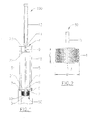
- Fig. 1 is a diagram of an exemplary model of the apparatus presently disclosed.
- Fig. 2 is an enlarged diagram of an exemplary embodiment for the brush part of the apparatus.
- An exemplary embodiment of the apparatus 100 includes at least one brush 50 which comprises a plurality of bristles 1, wherein the bristles 1 are connected to a first end 2 of an elongated support column 15.
- the brush 50 is enclosed inside a vessel 6, such as a steam relief vessel or other positively or negatively pressurized vessel or non-pressurized vessel, and situated inside a screen basket 10, such as a cylindrical perforated screen.
- a vessel 6 such as a steam relief vessel or other positively or negatively pressurized vessel or non-pressurized vessel
- a screen basket 10 such as a cylindrical perforated screen.
- One exemplary design of the brush 50 is such that the bristles 1 extend directly out of the elongated support column 15.
- Another exemplary design of the brush 50 is such that the bristles 1 extend out of a bristle housing 3, as shown in FIG.
- An exemplary length L of the brush 50 extending from the elongated support column 15 measured between the bottom of a lowest vertically located bristle and the top of a highest vertically located bristle is between about 25.4 cm (about 10 inches) to about 152.4 cm (about 60 inches) and all ranges in between depending upon the equipment size.
- preferred ranges could include, but are not limited to, between about 50.8 cm (about 20 inches) to about 91.44 cm (about 36 inches), or between about 91.44 cm (about 36 inches) to about 152.4 cm (about 60 inches), or between about 25.4 cm (about 10 inches) to about 60.96 cm (about 24 inches), or between about 25.4 cm (about 10 inches) to about 76.2 cm (about 30 inches), as sized in accordance to a vessel.
- the brush 50 has a width W , measured horizontally from a bristle tip on one side of the elongated support column 15 to the bristle tip on an opposite side of the elongated support column 15, of between about 10.16 cm (about 4 inches) to about 121.92 cm (about 48 inches) and all ranges in between depending upon the equipment size. Some examples of preferred ranges could include, but are not limited to between about 20.32 cm (about 8 inches) to about 91.44 cm (about 36 inches), or between 20.32 cm (8 inches) and 60.96 cm (24 inches), or between 20.32 cm (8 inches) and 45.72 cm (18 inches).
- the bristles' lengths are such that the bristles 1 are generally directly in contact with the screen basket 10 that the brush 50 is situated within.
- Exemplary embodiments of the brush 50 include conventional brushes known in the art and their various configurations.
- Exemplary embodiments of the bristles 1 extending out of the bristle housing 3 include, and are not limited to, a grid design that contains certain square surfaces without bristles, a spiral design that contains certain spiraled surfaces without bristles, a layered design that contains certain horizontal surfaces without bristles, and an equidistant design that contains bristles which are equally spaced on the surface of the bristle housing 3. Further exemplary designs stem from the bristle designs described above that may extend out directly from the elongated support column 15.
- the bristles 1 may comprise a stiff non-corrosive type of material that can withstand a pressure up to about 35 pound-force per square inch gauge (psig), with a preferred pressure range of between about 0 psig to about 10 psig, or between about 10 psig to about 25 psig, or between about 10 psig to about 35 psig, or between about 15 psig to about 25 psig, or between about 25 psig to about 35 psig.
- the material preferably comprises, but is not limited to, steel, nylon, a stiff composite, a composite coated metal, or any combination of the above.
- Composition material for the brush 50 can vary depending upon the environment to which the brush 50 will be subjected.
- an exemplary model of the apparatus 100 used to clean a steam relief strainer screen basket can comprise steel; another exemplary model subject to an acidic environment can comprise nylon bristles.
- An additional exemplary model of the apparatus 100 to be used to clean a steam relief strainer screen basket inside a chip bin can comprise a non-corrosive and non-static material such as a composite to avoid causing sparks.
- the elongated support column 15 which has a second end 4 (opposite of the first end 2 that is adjacent to the brush 50), extends through a coupling 9 adjacent said second end.
- the elongated support column 15 also extends through a fixed cover 23, which is adjacent a transpositive assembly 13 at the second end 4.
- the elongated support column 15 extends at the first end 2 through an aperture 8 in a removable vessel cover 21.
- the aperture 8 is operatively sealed with seal 7 to maintain the constant pressure in the vessel 6 as well as preventing uncontrolled release of steam or impurities to the atmosphere while allowing the elongated support column 15 to provide brush movement inside the vessel 6.
- the seal 7 preferably comprises, but is not limited to, a flexible composite comprising a non-ferrous material such as molybdenum, a thermoplastic material such as polytetrafluoroethylene (PTFE), graphite, a composite of graphite and a metal, a ceramic, a tertiaryfluorohydrocarbon, or a combination thereof that is capable of enduring the frequent movement of elongated support column 15.
- the elongated support column 15 comprises a non-corrosive material that is able to endure the pressure of the vessel, and the pressure caused by the frequent movement of the brush to clean the screen basket 10 within vessel 6, without breaking.
- the second end 4 of the elongated support column 15 is operatively and removably attached to the transpositive assembly 13 that provides the necessary movement for brush 50, and such that the transpositive assembly 13 can be removed from the elongated support column 15 as needed.
- the term "transpositive assembly” presently encompasses any assembly for changing the position of the brush. Exemplary designs of the transpositive assembly 13 include conventional mechanisms known in the art that provide movement and their configurations.
- the elongated support column (15) is operated one of manually and automatically.
- the exemplary movements of the elongated support column 15 can be one of vertical, horizontal, spiral, rotational, or a combination thereof.
- An exemplary transpositive assembly 13 can be, but is not limited to, one of a pressurized air cylinder, a steam powered cylinder, a hydraulic cylinder, a mechanical pulley, a lever system, an electrically driven assembly, or any combination thereof.
- the exemplary transpositive assembly 13 can also be automatic, manual, or a combination of both.
- the object of the transpositive assembly 13 is to provide movement to the brush 50 that allows the bristles 1 to graze the screen basket 10 and dislodge the layer of impurities.
- the transpositive assembly 13 is situated above and supported by a support housing 5, wherein the support housing 5 comprises a first end at removable vessel cover 21 and a second end at fixed cover 23 opposite the first end.
- the second end of the support housing 5 is operatively connected to the transpositive assembly 13 at the fixed cover 23.
- the removable vessel cover 21 has a first side and a second side, the second side faces the brush 50 on the interior of the pressurized vessel chamber 6 and the first side is operatively attached to and contacts the support housing 5.
- the removable vessel cover 21 is operatively attached to the support housing 5 first end, such as, and not limited to, by being bolted. Bolts 17 are positioned to attach the removable vessel cover 21 to the support housing 5.
- a coupling 9 positioned on the elongated support column 15 second end allows the transpositive assembly 13 to be attached to elongated support column 15.
- guide 11, located above or near the coupling 9 ensures that the transpositive assembly 13 is positioned in line with the elongated support column 15 within support housing 5.
- a handle 22 is attached at an end of coupling 9 adjacent the second end 4 of elongated support column 15. Handle 22 allows the elongated support column 15 to be moved in a vertical direction manually, facilitating manual movement of the brush 50 against the screen basket 10. The handle 22 may be situated such that a person can manually operate the brush 50 to reach the screen basket 10 without opening the vessel 6.
- the support housing 5 could be either enclosed or open to the environment.
- the support housing 5 can be fabricated from a material such as a light weight metal that is able to hold the weight and force of the transpositive assembly 13 when the mechanical means provides movement to the elongated support column 15.
- An exemplary design comprises a tripod design with three metal legs that are bolted to the vessel's removable vessel cover 21 at the first end of the support housing 5. The second end of the support housing 5, which is directly opposite the first end mentioned above, removably supports the transpositive assembly 13.
- each part of the apparatus 100 can be assembled and disassembled, as desired, to replace any fatigued parts, such as, but not limited to, the brush 50, the elongated support column 15, the seal 7, the support housing 5, and the transpositive assembly, 13.
- the elongated support column 15 is attached to a continuous mechanism to allow automatic operation of the elongated support column 15.
- the apparatus 100 comprises at least one brush 50, a vapor relief steam cleaning brush 50, an elongated support column 15 having a first end 2 and a second end 4, with the second end 4 opposite the first end 2; a bristle housing 3 operatively attached to the first end 2 of the elongated support column 15; a plurality of bristles 1 extending out of the bristle housing 3; a removable vessel cover 21 comprising a first side and a second side opposite the first side with an aperture 8 adjacent the first side; and at least one seal 7, the at least one seal 7 filling at least one aperture 8 of the removable vessel cover 21, wherein the elongated support column 15 extends through the at least one seal 7, and wherein the first end 2 of the elongated support column 15 faces the first side of the removable vessel cover 21, and the second end 4 of the elongated support column
- One embodiment of the screen brush apparatus 100 has a plurality of bristles 1 attached directly to the elongated support column 15 and the bristles 1 may be comprised of a steel, a nylon, a stiff composite material, a composite coated metal, or any combination thereof.
- the elongated support column 15 is comprised of a non-corrosive material and where the elongated support column 15 further comprises at least one handle 22 and can be operated manually or automatically (without the use of handle 22).
- the apparatus 100 can be grounded or can comprise a non-static causing material.
- an apparatus 100 for dislodging impurities on steam relief screen basket 10 within an operating vessel 6, such as an operating vessel 6 in a kraft mill comprises at least one brush, a vapor relief steam cleaning brush 50, and further comprises an elongated support column 15 having a first end 2 and a second end 4, with the second end 4 opposite the first end 2; a plurality of bristles 1 operatively attached to the elongated support column 15; a removable vessel cover 21 comprising a first side and a second side opposite the first side; and at least one seal 7, the at least one seal 7 filling at least one aperture 8 of the removable vessel cover 21, wherein the elongated support column 15 extends through the at least one seal 7, and wherein the first end 2 of the elongated support column 15 faces the first side of the removable vessel cover 21, and the second end 4 of the elongated support column 15 faces the second side of the removable vessel cover 21.
- a method for dislodging or cleaning impurities on or attached to a steam relief screen basket 10 within an operating vessel 6 is disclosed herein, such as an operating vessel 6 in a kraft mill, the method comprising: removing a removable vessel cover 21 of a vessel 6; locating a steam relief screen basket 10 inside the vessel 6; locating a brush 50 adjacent to the steam relief screen basket 10, wherein the brush 50 comprises a plurality of bristles 1, and the brush 50 being operatively attached to a first end 2 of an elongated support column 15, the elongated support column 15 having a first end 2 and a second end 4; contacting the plurality of bristles 1 of the brush 50 with the screen basket 10; extending a first end 2 of the elongated support column 15 through at least one seal 7, the seal 7 filling at least one aperture 8 inside a removable vessel cover 21 of the vessel 6; and closing the removable vessel cover 21 of the vessel 6 to avoid pressure drop inside the vessel 6 and moving the brush 50 from a first location on the screen basket 10 to a
- the method includes moving in a back and forth motion between the first and the second location on the screen basket 10 a brush-like device with extended bristles 1 to scrape the surface of a filter, such as a steam relief strainer screen basket 10. Movement of the bristles 1 creates direct abrasion on the layer of impurities attached to the screen basket 10 to detach the impurities.
- the brush 50 contacts and cleans the entire surface of the filter rather than only contacting and cleaning specific areas on the filter that are directly in line with the steam nozzles, as is the major drawback of conventional equipment and methods. Movement of the brush 50 may be continuous. Additionally, movement of the brush 50 may be at least one of pivotal, vertical, horizontal, spiral, rotational, or a combination of these. The brush 50 may be moved manually, automatically, or a combination thereof.
Landscapes
- Chemical & Material Sciences (AREA)
- Chemical Kinetics & Catalysis (AREA)
- Cleaning In General (AREA)
Abstract
Description
- In a conventional manufacturing process of pulp production from wood chips, flows of steam are inputted into various vessels. Due to the nature of the substrates present inside the vessel, such as wood chips and pulp, the steam that passes through the substrates will carry wood fibers and other light weight impurities that are not easily condensable. Consequently, the impurities will rise with the steam and other non-condensable gases, and attach to the screen basket or screen (also referred to as a strainer or a filter for use in any location where steam is being screened, strained or filtered) of a vessel, such as steam relief vessel, at the steam relief valve, creating clogs in the filtering or screening process. The steam is released through a steam relief vessel that contains a steam relief screen basket (screen basket) to filter out the impurities and fibers that arise with the steam and non-condensable gases before the vapor exits the vessel. The screen basket is typically located within a steam relief strainer (or steam relief chamber) within the vessel. The steam relief vessel is present in machines such as steaming vessels and chip bins used in the kraft pulping process. An example of a conventional screen basket used in such a practice is a steam relief strainer (usually cylindrical in shape) that is placed inside the steam relief vessel.
- On a steam relief vessel, there is at least one exit steam relief valve in place that allows the steam to be released from the vessel. Conventional means of clearing a steam relief screen basket of impurities include shutting off the relief valve periodically, and releasing a burst of steam backward through the steam relief screen basket at a pressure higher than the pressure in the vessel. This practice is called the "steam blow-back method."
- Conventionally, the blow-back steam is obtained through an extension of the steam pipe that supplies the steam to the vessel. The blow-back steam is at a pressure higher than the pressure in the vessel before it is released through the steam nozzles into the steam relief chamber. During the procedure, the steam relief valve is normally closed: no steam is relieved out of the vessel and the pressure is allowed to build up inside the vessel. Because of the pressure buildup from the closing of the relief valve and the pressured blow-back steam, the procedure is performed periodically and infrequently for a short period of time.
- This blow-back action of the conventional method creates openings in a layer of impurities that collects on the screen basket, which temporarily clears part of the screen basket of impurities. The openings allow for further filtering until another layer of impurities builds up again on the screen basket surface. For example, such a cleaning procedure performed on the cylindrical steam relief screen basket would require numerous steam nozzles to be mounted on the steam relief chamber that houses the cylindrical screen basket. The blow-back steam would reenter the steam relief chamber through the steam nozzles, and create openings in the area of the screen basket that is directly in line with the steam nozzles. The openings allow for further filtering until the opening is covered with impurities, at which time yet another blow-back cycle must be initiated.
- Conventional filter cleaning methods are not efficient and are disruptive to the relief filtering process. The conventional procedure allows for the periodic cleaning of only a small area of the screen basket at a time, while other areas of the screen basket may not be cleaned at all. The screen basket becomes inefficient after a layer of impurities settles on the screen basket, even after periodic cleaning. Furthermore, periodic disruptions in the flow of steam through the steam relief vessel are caused by the shutdown of the steam relief valve during the cleaning process. Accordingly, there is a need for an improved screen basket cleaning method that will improve the screen basket effectiveness in the vessel without causing a disruption in the continuous manufacturing process of pulp production. It is to this end and other needs the present disclosure is directed.
- A vapor relief steam cleaning brush (brush) has been conceived that addresses the above-discussed screen basket cleaning inefficiency by presenting an apparatus that is capable of cleaning an increased amount of a surface area of a screen basket in a single cycle. For example, the apparatus can be used to clean a cylindrical perforated screen basket in a steam relief vessel in a kraft pulping process. The apparatus can be utilized for any screen basket that filters solids and liquids from vapor and non-condensable gases to allow the vapor and non-condensable gases to pass through the screen basket. A cleaning method has also been conceived comprising moving a brush-like device with extended bristles to scrape the surface of a screen basket, such as a steam relief strainer screen basket. Movement of the bristles creates direct abrasion on the layer of impurities attached to the screen basket to detach the impurities. The brush contacts and cleans the entire surface of the screen basket rather than contacting and cleaning only specific areas of the screen basket that are directly in line with the steam nozzles, as is the drawback of conventional equipment and methods.
- The brush as described herein does not require disruption of the vapor flow while the filter is being cleaned. An embodiment of the disclosed undisruptive method prevents the potential of excess pressure buildup during the cleaning process due to the vapor outlet being shut off. While the brush apparatus is in motion, the vapor is able to flow through the steam relief vessel continuously under a constant pressure. Furthermore, because the apparatus can operate without disrupting vapor flow, the apparatus can be operated as often as is desired to maximize filtering efficiencies. Nonetheless, the presently disclosed method does not preclude a conventional cleaning method. Another embodiment of the disclosed undisruptive method and apparatus allows for use to clean the screen baskets in non-pressurized vessels or even vessels operating under a vacuum.
- The present disclosure is not limited to the exemplary models described, and can be modified in size, material, and design to accommodate other types of screen baskets used in a vessel that separate vapor and non-condensible gases from solids and liquids. These features, and other features and advantages of the present invention will become more apparent to those of ordinary skill in the art when the following detailed description of the preferred embodiments is read in conjunction with the appended figures.
-
Fig. 1 is a diagram of an exemplary model of the apparatus presently disclosed. -
Fig. 2 is an enlarged diagram of an exemplary embodiment for the brush part of the apparatus. - An exemplary embodiment of the
apparatus 100, shown inFIGs. 1 and 2 , includes at least onebrush 50 which comprises a plurality of bristles 1, wherein the bristles 1 are connected to afirst end 2 of anelongated support column 15. Thebrush 50 is enclosed inside a vessel 6, such as a steam relief vessel or other positively or negatively pressurized vessel or non-pressurized vessel, and situated inside ascreen basket 10, such as a cylindrical perforated screen. One exemplary design of thebrush 50 is such that the bristles 1 extend directly out of theelongated support column 15. Another exemplary design of thebrush 50 is such that the bristles 1 extend out of abristle housing 3, as shown inFIG. 2 , which is operatively attached to theelongated support column 15 adjacent thefirst end 2. An exemplary length L of thebrush 50 extending from theelongated support column 15 measured between the bottom of a lowest vertically located bristle and the top of a highest vertically located bristle is between about 25.4 cm (about 10 inches) to about 152.4 cm (about 60 inches) and all ranges in between depending upon the equipment size. Some examples of preferred ranges could include, but are not limited to, between about 50.8 cm (about 20 inches) to about 91.44 cm (about 36 inches), or between about 91.44 cm (about 36 inches) to about 152.4 cm (about 60 inches), or between about 25.4 cm (about 10 inches) to about 60.96 cm (about 24 inches), or between about 25.4 cm (about 10 inches) to about 76.2 cm (about 30 inches), as sized in accordance to a vessel. Thebrush 50 has a width W, measured horizontally from a bristle tip on one side of theelongated support column 15 to the bristle tip on an opposite side of theelongated support column 15, of between about 10.16 cm (about 4 inches) to about 121.92 cm (about 48 inches) and all ranges in between depending upon the equipment size. Some examples of preferred ranges could include, but are not limited to between about 20.32 cm (about 8 inches) to about 91.44 cm (about 36 inches), or between 20.32 cm (8 inches) and 60.96 cm (24 inches), or between 20.32 cm (8 inches) and 45.72 cm (18 inches). - In all of the embodiments, the bristles' lengths are such that the bristles 1 are generally directly in contact with the
screen basket 10 that thebrush 50 is situated within. Exemplary embodiments of thebrush 50 include conventional brushes known in the art and their various configurations. Exemplary embodiments of the bristles 1 extending out of thebristle housing 3 include, and are not limited to, a grid design that contains certain square surfaces without bristles, a spiral design that contains certain spiraled surfaces without bristles, a layered design that contains certain horizontal surfaces without bristles, and an equidistant design that contains bristles which are equally spaced on the surface of thebristle housing 3. Further exemplary designs stem from the bristle designs described above that may extend out directly from theelongated support column 15. - The bristles 1 may comprise a stiff non-corrosive type of material that can withstand a pressure up to about 35 pound-force per square inch gauge (psig), with a preferred pressure range of between about 0 psig to about 10 psig, or between about 10 psig to about 25 psig, or between about 10 psig to about 35 psig, or between about 15 psig to about 25 psig, or between about 25 psig to about 35 psig. The material preferably comprises, but is not limited to, steel, nylon, a stiff composite, a composite coated metal, or any combination of the above. Composition material for the
brush 50 can vary depending upon the environment to which thebrush 50 will be subjected. For example, an exemplary model of theapparatus 100 used to clean a steam relief strainer screen basket can comprise steel; another exemplary model subject to an acidic environment can comprise nylon bristles. An additional exemplary model of theapparatus 100 to be used to clean a steam relief strainer screen basket inside a chip bin can comprise a non-corrosive and non-static material such as a composite to avoid causing sparks. - The
elongated support column 15, which has a second end 4 (opposite of thefirst end 2 that is adjacent to the brush 50), extends through acoupling 9 adjacent said second end. Theelongated support column 15 also extends through afixed cover 23, which is adjacent atranspositive assembly 13 at the second end 4. Opposite the second end 4, theelongated support column 15 extends at thefirst end 2 through an aperture 8 in aremovable vessel cover 21. The aperture 8 is operatively sealed with seal 7 to maintain the constant pressure in the vessel 6 as well as preventing uncontrolled release of steam or impurities to the atmosphere while allowing theelongated support column 15 to provide brush movement inside the vessel 6. The seal 7 preferably comprises, but is not limited to, a flexible composite comprising a non-ferrous material such as molybdenum, a thermoplastic material such as polytetrafluoroethylene (PTFE), graphite, a composite of graphite and a metal, a ceramic, a tertiaryfluorohydrocarbon, or a combination thereof that is capable of enduring the frequent movement ofelongated support column 15. Theelongated support column 15 comprises a non-corrosive material that is able to endure the pressure of the vessel, and the pressure caused by the frequent movement of the brush to clean thescreen basket 10 within vessel 6, without breaking. - The second end 4 of the
elongated support column 15 is operatively and removably attached to thetranspositive assembly 13 that provides the necessary movement forbrush 50, and such that thetranspositive assembly 13 can be removed from theelongated support column 15 as needed. The term "transpositive assembly" presently encompasses any assembly for changing the position of the brush. Exemplary designs of thetranspositive assembly 13 include conventional mechanisms known in the art that provide movement and their configurations. The elongated support column (15) is operated one of manually and automatically. The exemplary movements of theelongated support column 15 can be one of vertical, horizontal, spiral, rotational, or a combination thereof. An exemplarytranspositive assembly 13 can be, but is not limited to, one of a pressurized air cylinder, a steam powered cylinder, a hydraulic cylinder, a mechanical pulley, a lever system, an electrically driven assembly, or any combination thereof. The exemplarytranspositive assembly 13 can also be automatic, manual, or a combination of both. The object of thetranspositive assembly 13 is to provide movement to thebrush 50 that allows the bristles 1 to graze thescreen basket 10 and dislodge the layer of impurities. - The
transpositive assembly 13 is situated above and supported by asupport housing 5, wherein thesupport housing 5 comprises a first end atremovable vessel cover 21 and a second end at fixedcover 23 opposite the first end. The second end of thesupport housing 5 is operatively connected to thetranspositive assembly 13 at the fixedcover 23. Theremovable vessel cover 21 has a first side and a second side, the second side faces thebrush 50 on the interior of the pressurized vessel chamber 6 and the first side is operatively attached to and contacts thesupport housing 5. Theremovable vessel cover 21 is operatively attached to thesupport housing 5 first end, such as, and not limited to, by being bolted.Bolts 17 are positioned to attach theremovable vessel cover 21 to thesupport housing 5. Acoupling 9 positioned on theelongated support column 15 second end allows thetranspositive assembly 13 to be attached toelongated support column 15. In addition, guide 11, located above or near thecoupling 9 ensures that thetranspositive assembly 13 is positioned in line with theelongated support column 15 withinsupport housing 5. Ahandle 22 is attached at an end ofcoupling 9 adjacent the second end 4 ofelongated support column 15.Handle 22 allows theelongated support column 15 to be moved in a vertical direction manually, facilitating manual movement of thebrush 50 against thescreen basket 10. Thehandle 22 may be situated such that a person can manually operate thebrush 50 to reach thescreen basket 10 without opening the vessel 6. - An exemplary design of the
support housing 5 could be either enclosed or open to the environment. Thesupport housing 5 can be fabricated from a material such as a light weight metal that is able to hold the weight and force of thetranspositive assembly 13 when the mechanical means provides movement to theelongated support column 15. An exemplary design comprises a tripod design with three metal legs that are bolted to the vessel'sremovable vessel cover 21 at the first end of thesupport housing 5. The second end of thesupport housing 5, which is directly opposite the first end mentioned above, removably supports thetranspositive assembly 13. - In addition, each part of the
apparatus 100 can be assembled and disassembled, as desired, to replace any fatigued parts, such as, but not limited to, thebrush 50, theelongated support column 15, the seal 7, thesupport housing 5, and the transpositive assembly, 13. - In yet another exemplary model of the
apparatus 100, theelongated support column 15 is attached to a continuous mechanism to allow automatic operation of theelongated support column 15. - In addition, one embodiment of the
screen brush apparatus 100 for dislodging impurities on steam relief screens within an operating vessel, such as an operating vessel in a kraft mill, has been conceived. Theapparatus 100 comprises at least onebrush 50, a vapor reliefsteam cleaning brush 50, anelongated support column 15 having afirst end 2 and a second end 4, with the second end 4 opposite thefirst end 2; a bristlehousing 3 operatively attached to thefirst end 2 of theelongated support column 15; a plurality of bristles 1 extending out of thebristle housing 3; aremovable vessel cover 21 comprising a first side and a second side opposite the first side with an aperture 8 adjacent the first side; and at least one seal 7, the at least one seal 7 filling at least one aperture 8 of theremovable vessel cover 21, wherein theelongated support column 15 extends through the at least one seal 7, and wherein thefirst end 2 of theelongated support column 15 faces the first side of theremovable vessel cover 21, and the second end 4 of theelongated support column 15 faces the second side of the fixedcover 23 and is adjacent thetranspositive assembly 13. - One embodiment of the
screen brush apparatus 100 has a plurality of bristles 1 attached directly to theelongated support column 15 and the bristles 1 may be comprised of a steel, a nylon, a stiff composite material, a composite coated metal, or any combination thereof. - In another embodiment of the
screen brush apparatus 100, theelongated support column 15 is comprised of a non-corrosive material and where theelongated support column 15 further comprises at least onehandle 22 and can be operated manually or automatically (without the use of handle 22). - In an alternative exemplary embodiment, wherein the
apparatus 100 is used in an environment where static electricity may be of concern, theapparatus 100 can be grounded or can comprise a non-static causing material. - In another embodiment, an
apparatus 100 for dislodging impurities on steamrelief screen basket 10 within an operating vessel 6, such as an operating vessel 6 in a kraft mill, theapparatus 100 comprises at least one brush, a vapor reliefsteam cleaning brush 50, and further comprises anelongated support column 15 having afirst end 2 and a second end 4, with the second end 4 opposite thefirst end 2; a plurality of bristles 1 operatively attached to theelongated support column 15; aremovable vessel cover 21 comprising a first side and a second side opposite the first side; and at least one seal 7, the at least one seal 7 filling at least one aperture 8 of theremovable vessel cover 21, wherein theelongated support column 15 extends through the at least one seal 7, and wherein thefirst end 2 of theelongated support column 15 faces the first side of theremovable vessel cover 21, and the second end 4 of theelongated support column 15 faces the second side of theremovable vessel cover 21. - A method for dislodging or cleaning impurities on or attached to a steam
relief screen basket 10 within an operating vessel 6 is disclosed herein, such as an operating vessel 6 in a kraft mill, the method comprising: removing aremovable vessel cover 21 of a vessel 6; locating a steamrelief screen basket 10 inside the vessel 6; locating abrush 50 adjacent to the steamrelief screen basket 10, wherein thebrush 50 comprises a plurality of bristles 1, and thebrush 50 being operatively attached to afirst end 2 of anelongated support column 15, theelongated support column 15 having afirst end 2 and a second end 4; contacting the plurality of bristles 1 of thebrush 50 with thescreen basket 10; extending afirst end 2 of theelongated support column 15 through at least one seal 7, the seal 7 filling at least one aperture 8 inside aremovable vessel cover 21 of the vessel 6; and closing theremovable vessel cover 21 of the vessel 6 to avoid pressure drop inside the vessel 6 and moving thebrush 50 from a first location on thescreen basket 10 to a second location on thescreen basket 10 to dislodge impurities attached to thescreen basket 10. - In one embodiment of the invention, the method includes moving in a back and forth motion between the first and the second location on the screen basket 10 a brush-like device with extended bristles 1 to scrape the surface of a filter, such as a steam relief
strainer screen basket 10. Movement of the bristles 1 creates direct abrasion on the layer of impurities attached to thescreen basket 10 to detach the impurities. Thebrush 50 contacts and cleans the entire surface of the filter rather than only contacting and cleaning specific areas on the filter that are directly in line with the steam nozzles, as is the major drawback of conventional equipment and methods. Movement of thebrush 50 may be continuous. Additionally, movement of thebrush 50 may be at least one of pivotal, vertical, horizontal, spiral, rotational, or a combination of these. Thebrush 50 may be moved manually, automatically, or a combination thereof. - It is to be understood that the present invention is by no means limited to the particular construction.
- Apparatus and method steps herein disclosed or shown in the drawings also comprise any modifications or equivalents within the scope of the claims known in the art. It will be appreciated by those skilled in the art that the devices and methods herein disclosed will find utility with respect to multiple vessels of similar capabilities as disclosed in the exemplary embodiments for this disclosure.
- The forgoing detailed description of the preferred embodiments is presented only for illustrative and descriptive purposes and is not intended to be exhaustive or to limit the scope and spirit of the invention. The embodiments were selected and described to best explain the principles of the invention and its practical applications. One of ordinary skill in the art will recognize variations can be made to the invention disclosed in this specification without departing from the scope of the invention, as it is defined by the appended claims.
Claims (16)
- An apparatus (100) for dislodging impurities on a steam relief screen basket (10) within an operating vessel (6) comprising at least one brush (50), wherein the at least one brush (50) comprises:an elongated support column (15) having a first end (2) and a second end (4) opposite to the first end (2);a bristle housing (3) operatively attached to the first end (2) of the elongated support column (15);a plurality of bristles (I) extending out of the bristle housing (3);a transpositive assembly (13) adjacent the second end (4) of the elongated support column (15);a removable vessel cover (21) comprising a first side and a second side opposite of the first side, the removable vessel cover (21) having an aperture (8); andat least one seal (7) filling the aperture (8) of the removable vessel cover (21), wherein the elongated support column (15) extends through the seal (7), and wherein the first end (2) of the elongated support column (15) is adjacent the brush (50).
- The apparatus (100) of claim 1, wherein the apparatus (100) is composed of a non-static causing material, and/or the apparatus (100) is grounded.
- The apparatus (100) of claim 1 or 2, wherein the plurality of bristles (1) are attached directly to the elongated support column (15).
- The apparatus (100) of any one of claims 1 to 3, wherein the plurality of bristles (1) are comprised of one of a steel, a nylon, a stiff composite, a composite coated metal, and a combination thereof.
- The apparatus (100) of any one of the preceding claims, wherein the elongated support column (15) is comprised of a non-corrosive material.
- The apparatus (100) of any one of the preceding claims, wherein the seal (7) comprises at least one of a flexible composite, the flexible composite comprising one of a non-ferrous material such as molybdenum, a thermoplastic material such as polytetrafluoroethylene (PTFE), graphite, a composite of graphite and a metal, a ceramic, a tertiaryfluorohydrocarbon and any combination thereof.
- The apparatus (100) of any one of the preceding claims, wherein the elongated support column (15) further comprises at least one handle (22).
- The apparatus (100) of any one of the preceding claims, further comprising a support housing (5), the support housing (5) further comprising a first end and a second end opposite to the first end, wherein the first end is operatively attached to the first side of the removable vessel cover (21).
- The apparatus (100) of claim 8, wherein the transpositive assembly (13) is operatively supported by the second end of the support housing (5), and wherein the transpositive assembly (13) is operatively and removably attached to the second end (4) of the elongated support column (15).
- The apparatus (100) of any one of the preceding claims, wherein the transpositive assembly (13) comprises one of a pressurized air cylinder, a steam powered cylinder, a hydraulic cylinder, a mechanical pulley, a lever system, an electrically driven assembly, or any combination thereof, and the transpositive assembly (13) is operated one of automatically, manually, and a combination thereof.
- The apparatus (100) of any one of the preceding claims, wherein
a length (L) of the brush (50) extending from the elongated support column (15) measured between the bottom of a lowest vertically located bristle and the top of a highest vertically located bristle is between about 25.4 cm (about 10 inches) to about 152.4 cm (about 60 inches) and all ranges in between; and/or
the brush (50) has a width (W) measured horizontally from a bristle tip on one side of the elongated support column (15) to the bristle tip on the opposite side of the elongated support column (15), which is between about 10.16 cm (about 4 inches) to about 121.92 cm (about 48 inches) and all ranges in between. - An apparatus (100) for dislodging impurities on steam relief screen basket (10) within an operating vessel (6), comprising at least one brush (50), wherein the at least one brush (50) comprises:an elongated support column (15) having a first end (2) and a second end (4), with the second end (4) opposite the first end (2);a plurality of bristles (1) operatively attached to the elongated support column (15);a removable vessel cover (21) comprising a first side and a second side opposite the first side;at least one seal (7), the at least one seal (7) filling at least one aperture (8) of the removable vessel cover (21), wherein the elongated support column (15) extends through the at least one seal (7), and wherein the first end (2) of the elongated support column (15) faces the first side of the removable vessel cover (21), and the second end (4) of the elongated support column (15) faces the second side of a fixed cover (23).
- A method for dislodging impurities on a steam relief screen basket (10) within an operating vessel (6) comprising:removing a removable vessel cover (21) of a vessel (6);locating a steam relief screen basket (10) inside the vessel (6);locating a brush (50) adjacent to the steam relief screen basket (10), wherein the brush (50) comprises a plurality of bristles (1), the brush (50) being operatively attached to a first end (2) of an elongated support column (15);contacting the plurality of bristles (1) with the screen basket (10);extending a second end (4) of the elongated support column (15) through at least one seal (7) that fills at least one aperture (8) inside a removable vessel cover (21) of the vessel (6);closing the removable vessel cover (21) of the vessel (6) to avoid pressure drop inside the vessel (6); andmoving the brush (50) from a first location on the screen basket (10) to a second location on the screen basket (10) to dislodge impurities attached to the screen basket (10).
- The method of claim 13, wherein the brush (50) moves back and forth between the first location on the screen basket (10) and the second location on the screen basket (10).
- The method of claim 13 or 14, wherein the brush (50) moves continuously.
- The method of any one of claims 13 to 15, wherein the brush movement comprises at least one of pivotal, vertical, horizontal, spiral, rotational, and a combination thereof.
Applications Claiming Priority (2)
| Application Number | Priority Date | Filing Date | Title |
|---|---|---|---|
| US201261668581P | 2012-07-06 | 2012-07-06 | |
| US13/911,145 US9475098B2 (en) | 2012-07-06 | 2013-06-06 | Vapor relief screen basket cleaning brush and method |
Publications (2)
| Publication Number | Publication Date |
|---|---|
| EP2684997A1 true EP2684997A1 (en) | 2014-01-15 |
| EP2684997B1 EP2684997B1 (en) | 2015-03-04 |
Family
ID=48740909
Family Applications (1)
| Application Number | Title | Priority Date | Filing Date |
|---|---|---|---|
| EP13174482.3A Not-in-force EP2684997B1 (en) | 2012-07-06 | 2013-07-01 | Vapor relief screen basket cleaning brush and method |
Country Status (6)
| Country | Link |
|---|---|
| US (1) | US9475098B2 (en) |
| EP (1) | EP2684997B1 (en) |
| BR (1) | BR102013017277A2 (en) |
| CA (1) | CA2819540C (en) |
| CL (1) | CL2013001949A1 (en) |
| PT (1) | PT2684997E (en) |
Cited By (1)
| Publication number | Priority date | Publication date | Assignee | Title |
|---|---|---|---|---|
| CN106378320A (en) * | 2016-11-09 | 2017-02-08 | 安徽千禧精密轴承制造有限公司 | Bearing inner ring cleaning device |
Families Citing this family (5)
| Publication number | Priority date | Publication date | Assignee | Title |
|---|---|---|---|---|
| US11083985B2 (en) | 2017-01-20 | 2021-08-10 | Andritz Inc. | Vapor relief strainer with cleaner |
| CN111085471A (en) * | 2019-11-25 | 2020-05-01 | 徐州鑫泰镀锌设备有限公司 | Hot galvanizing production and processing product belt cleaning device |
| CN112562478B (en) * | 2020-12-24 | 2022-05-03 | 安徽商贸职业技术学院 | Simulation sand table assembly for enterprise planning management |
| CN114082254A (en) * | 2021-11-16 | 2022-02-25 | 浙江铭鑫冷链设备有限公司 | Air cooler aerodynamic assembly |
| CN114405109A (en) * | 2022-03-30 | 2022-04-29 | 杭州加淼科技有限公司 | Prevent stifled barrier removal immersible pump |
Citations (6)
| Publication number | Priority date | Publication date | Assignee | Title |
|---|---|---|---|---|
| GB186801A (en) * | 1921-09-02 | 1922-10-12 | Percy St George Kirke | Improvements relating to the cleaning of fire tube boilers |
| GB535976A (en) * | 1939-10-25 | 1941-04-29 | Richard Stewart Walde | Improvements in or relating to the cleaning of drums, barrels or the like |
| AU453442B2 (en) * | 1970-10-29 | 1974-10-03 | Brian John Daff | Pipe cleaning device |
| US4021265A (en) * | 1975-12-04 | 1977-05-03 | Bell Telephone Laboratories, Incorporated | Method and apparatus for cleaning tubular structures |
| DE3428133A1 (en) * | 1983-06-24 | 1986-02-13 | Werner Dr.med. 4330 Mülheim Schubert | Cleaning head for pipe cleaning device for removing hard encrustations in pipelines |
| FR2687084A1 (en) * | 1992-02-06 | 1993-08-13 | Framatome Sa | Device for the remote cleaning of the inside walls of a tube |
Family Cites Families (5)
| Publication number | Priority date | Publication date | Assignee | Title |
|---|---|---|---|---|
| FR1471470A (en) * | 1965-03-16 | 1967-05-24 | ||
| US5183568A (en) * | 1991-08-22 | 1993-02-02 | G A Industries, Inc. | Self-cleaning strainer |
| US5437630A (en) * | 1993-10-27 | 1995-08-01 | Stryker Corporation | Arthroscopic cutter having curved rotatable drive |
| KR100768080B1 (en) * | 2007-04-25 | 2007-10-17 | 아쿠소프트주식회사 | Filter unit with screen brush |
| KR101331576B1 (en) * | 2011-05-17 | 2013-11-21 | 경남한일개발주식회사 | A cleaning apparatus of a well-water basin with brush |
-
2013
- 2013-06-06 US US13/911,145 patent/US9475098B2/en not_active Expired - Fee Related
- 2013-06-18 CA CA2819540A patent/CA2819540C/en not_active Expired - Fee Related
- 2013-07-01 EP EP13174482.3A patent/EP2684997B1/en not_active Not-in-force
- 2013-07-01 PT PT131744823T patent/PT2684997E/en unknown
- 2013-07-02 CL CL2013001949A patent/CL2013001949A1/en unknown
- 2013-07-04 BR BRBR102013017277-4A patent/BR102013017277A2/en not_active IP Right Cessation
Patent Citations (6)
| Publication number | Priority date | Publication date | Assignee | Title |
|---|---|---|---|---|
| GB186801A (en) * | 1921-09-02 | 1922-10-12 | Percy St George Kirke | Improvements relating to the cleaning of fire tube boilers |
| GB535976A (en) * | 1939-10-25 | 1941-04-29 | Richard Stewart Walde | Improvements in or relating to the cleaning of drums, barrels or the like |
| AU453442B2 (en) * | 1970-10-29 | 1974-10-03 | Brian John Daff | Pipe cleaning device |
| US4021265A (en) * | 1975-12-04 | 1977-05-03 | Bell Telephone Laboratories, Incorporated | Method and apparatus for cleaning tubular structures |
| DE3428133A1 (en) * | 1983-06-24 | 1986-02-13 | Werner Dr.med. 4330 Mülheim Schubert | Cleaning head for pipe cleaning device for removing hard encrustations in pipelines |
| FR2687084A1 (en) * | 1992-02-06 | 1993-08-13 | Framatome Sa | Device for the remote cleaning of the inside walls of a tube |
Cited By (1)
| Publication number | Priority date | Publication date | Assignee | Title |
|---|---|---|---|---|
| CN106378320A (en) * | 2016-11-09 | 2017-02-08 | 安徽千禧精密轴承制造有限公司 | Bearing inner ring cleaning device |
Also Published As
| Publication number | Publication date |
|---|---|
| BR102013017277A2 (en) | 2015-06-30 |
| CA2819540A1 (en) | 2014-01-06 |
| CA2819540C (en) | 2019-10-08 |
| US20140007908A1 (en) | 2014-01-09 |
| US9475098B2 (en) | 2016-10-25 |
| CL2013001949A1 (en) | 2013-12-13 |
| PT2684997E (en) | 2015-04-02 |
| EP2684997B1 (en) | 2015-03-04 |
Similar Documents
| Publication | Publication Date | Title |
|---|---|---|
| US9475098B2 (en) | Vapor relief screen basket cleaning brush and method | |
| US11083985B2 (en) | Vapor relief strainer with cleaner | |
| DK3110521T3 (en) | Filtering arrangement for stepwise screening of fine and coarse particles in a single functional unit | |
| CN202237469U (en) | Self-cleaning filter device and dyeing machine comprising same | |
| CN204017488U (en) | Oil drop pot strainer is unloaded in oil field | |
| JP6343231B2 (en) | Filtration device | |
| CN111389385B (en) | Spiral separation and cleaning device and method for activity Jiao Lvliao | |
| CN115364549B (en) | Self-cleaning structure filter for cold trap | |
| CN117404651A (en) | Boiler scale cleaning device | |
| CN211724837U (en) | Self-cleaning pipeline filter | |
| JP6702650B2 (en) | Fibrous filter system and method for cleaning the fibrous filter system | |
| JP6718252B2 (en) | Filtration device | |
| CN113573793A (en) | Cleaning device and cleaning method for dust collector | |
| KR20120114791A (en) | Self cleaning strainer | |
| CN112274988A (en) | Centrifugal pump filter belt cleaning device | |
| CN210177269U (en) | Papermaking slurry screening device convenient to clean | |
| KR101387714B1 (en) | Oil filtering apparatus | |
| CN117504399A (en) | Scraper type self-cleaning filter | |
| KR102457238B1 (en) | Strainer for easily water washing | |
| CN209548839U (en) | One kind can auto-cleaning filter | |
| JP6928635B2 (en) | Filtration device and filter cleaning method for filtration device | |
| JP2013506832A (en) | Apparatus and method for cleaning nuclear fuel elements | |
| CN212881391U (en) | Filter equipment for oil spout bottle cleaner | |
| CA2992479A1 (en) | Vapor relief strainer with cleaner | |
| EP1483971B1 (en) | Apparatus for filtering fluid substances which can be used with a machine for injecting meat products |
Legal Events
| Date | Code | Title | Description |
|---|---|---|---|
| PUAI | Public reference made under article 153(3) epc to a published international application that has entered the european phase |
Free format text: ORIGINAL CODE: 0009012 |
|
| AK | Designated contracting states |
Kind code of ref document: A1 Designated state(s): AL AT BE BG CH CY CZ DE DK EE ES FI FR GB GR HR HU IE IS IT LI LT LU LV MC MK MT NL NO PL PT RO RS SE SI SK SM TR |
|
| AX | Request for extension of the european patent |
Extension state: BA ME |
|
| 17P | Request for examination filed |
Effective date: 20140220 |
|
| RBV | Designated contracting states (corrected) |
Designated state(s): AL AT BE BG CH CY CZ DE DK EE ES FI FR GB GR HR HU IE IS IT LI LT LU LV MC MK MT NL NO PL PT RO RS SE SI SK SM TR |
|
| GRAJ | Information related to disapproval of communication of intention to grant by the applicant or resumption of examination proceedings by the epo deleted |
Free format text: ORIGINAL CODE: EPIDOSDIGR1 |
|
| GRAP | Despatch of communication of intention to grant a patent |
Free format text: ORIGINAL CODE: EPIDOSNIGR1 |
|
| RIC1 | Information provided on ipc code assigned before grant |
Ipc: D21C 11/06 20060101AFI20140910BHEP |
|
| INTG | Intention to grant announced |
Effective date: 20140929 |
|
| GRAS | Grant fee paid |
Free format text: ORIGINAL CODE: EPIDOSNIGR3 |
|
| GRAA | (expected) grant |
Free format text: ORIGINAL CODE: 0009210 |
|
| RAP1 | Party data changed (applicant data changed or rights of an application transferred) |
Owner name: ANDRITZ INC. |
|
| AK | Designated contracting states |
Kind code of ref document: B1 Designated state(s): AL AT BE BG CH CY CZ DE DK EE ES FI FR GB GR HR HU IE IS IT LI LT LU LV MC MK MT NL NO PL PT RO RS SE SI SK SM TR |
|
| REG | Reference to a national code |
Ref country code: GB Ref legal event code: FG4D |
|
| REG | Reference to a national code |
Ref country code: CH Ref legal event code: EP |
|
| REG | Reference to a national code |
Ref country code: IE Ref legal event code: FG4D |
|
| REG | Reference to a national code |
Ref country code: PT Ref legal event code: SC4A Free format text: AVAILABILITY OF NATIONAL TRANSLATION Effective date: 20150318 |
|
| REG | Reference to a national code |
Ref country code: SE Ref legal event code: TRGR |
|
| REG | Reference to a national code |
Ref country code: AT Ref legal event code: REF Ref document number: 714028 Country of ref document: AT Kind code of ref document: T Effective date: 20150415 |
|
| REG | Reference to a national code |
Ref country code: DE Ref legal event code: R096 Ref document number: 602013001073 Country of ref document: DE Effective date: 20150416 |
|
| REG | Reference to a national code |
Ref country code: AT Ref legal event code: MK05 Ref document number: 714028 Country of ref document: AT Kind code of ref document: T Effective date: 20150304 Ref country code: NL Ref legal event code: VDEP Effective date: 20150304 |
|
| PG25 | Lapsed in a contracting state [announced via postgrant information from national office to epo] |
Ref country code: ES Free format text: LAPSE BECAUSE OF FAILURE TO SUBMIT A TRANSLATION OF THE DESCRIPTION OR TO PAY THE FEE WITHIN THE PRESCRIBED TIME-LIMIT Effective date: 20150304 Ref country code: LT Free format text: LAPSE BECAUSE OF FAILURE TO SUBMIT A TRANSLATION OF THE DESCRIPTION OR TO PAY THE FEE WITHIN THE PRESCRIBED TIME-LIMIT Effective date: 20150304 Ref country code: NO Free format text: LAPSE BECAUSE OF FAILURE TO SUBMIT A TRANSLATION OF THE DESCRIPTION OR TO PAY THE FEE WITHIN THE PRESCRIBED TIME-LIMIT Effective date: 20150604 Ref country code: HR Free format text: LAPSE BECAUSE OF FAILURE TO SUBMIT A TRANSLATION OF THE DESCRIPTION OR TO PAY THE FEE WITHIN THE PRESCRIBED TIME-LIMIT Effective date: 20150304 |
|
| REG | Reference to a national code |
Ref country code: LT Ref legal event code: MG4D |
|
| PG25 | Lapsed in a contracting state [announced via postgrant information from national office to epo] |
Ref country code: AT Free format text: LAPSE BECAUSE OF FAILURE TO SUBMIT A TRANSLATION OF THE DESCRIPTION OR TO PAY THE FEE WITHIN THE PRESCRIBED TIME-LIMIT Effective date: 20150304 Ref country code: GR Free format text: LAPSE BECAUSE OF FAILURE TO SUBMIT A TRANSLATION OF THE DESCRIPTION OR TO PAY THE FEE WITHIN THE PRESCRIBED TIME-LIMIT Effective date: 20150605 Ref country code: LV Free format text: LAPSE BECAUSE OF FAILURE TO SUBMIT A TRANSLATION OF THE DESCRIPTION OR TO PAY THE FEE WITHIN THE PRESCRIBED TIME-LIMIT Effective date: 20150304 Ref country code: RS Free format text: LAPSE BECAUSE OF FAILURE TO SUBMIT A TRANSLATION OF THE DESCRIPTION OR TO PAY THE FEE WITHIN THE PRESCRIBED TIME-LIMIT Effective date: 20150304 |
|
| PG25 | Lapsed in a contracting state [announced via postgrant information from national office to epo] |
Ref country code: NL Free format text: LAPSE BECAUSE OF FAILURE TO SUBMIT A TRANSLATION OF THE DESCRIPTION OR TO PAY THE FEE WITHIN THE PRESCRIBED TIME-LIMIT Effective date: 20150304 |
|
| PG25 | Lapsed in a contracting state [announced via postgrant information from national office to epo] |
Ref country code: SK Free format text: LAPSE BECAUSE OF FAILURE TO SUBMIT A TRANSLATION OF THE DESCRIPTION OR TO PAY THE FEE WITHIN THE PRESCRIBED TIME-LIMIT Effective date: 20150304 Ref country code: EE Free format text: LAPSE BECAUSE OF FAILURE TO SUBMIT A TRANSLATION OF THE DESCRIPTION OR TO PAY THE FEE WITHIN THE PRESCRIBED TIME-LIMIT Effective date: 20150304 Ref country code: RO Free format text: LAPSE BECAUSE OF FAILURE TO SUBMIT A TRANSLATION OF THE DESCRIPTION OR TO PAY THE FEE WITHIN THE PRESCRIBED TIME-LIMIT Effective date: 20150304 Ref country code: CZ Free format text: LAPSE BECAUSE OF FAILURE TO SUBMIT A TRANSLATION OF THE DESCRIPTION OR TO PAY THE FEE WITHIN THE PRESCRIBED TIME-LIMIT Effective date: 20150304 |
|
| PG25 | Lapsed in a contracting state [announced via postgrant information from national office to epo] |
Ref country code: IS Free format text: LAPSE BECAUSE OF FAILURE TO SUBMIT A TRANSLATION OF THE DESCRIPTION OR TO PAY THE FEE WITHIN THE PRESCRIBED TIME-LIMIT Effective date: 20150704 Ref country code: PL Free format text: LAPSE BECAUSE OF FAILURE TO SUBMIT A TRANSLATION OF THE DESCRIPTION OR TO PAY THE FEE WITHIN THE PRESCRIBED TIME-LIMIT Effective date: 20150304 |
|
| REG | Reference to a national code |
Ref country code: DE Ref legal event code: R097 Ref document number: 602013001073 Country of ref document: DE |
|
| PG25 | Lapsed in a contracting state [announced via postgrant information from national office to epo] |
Ref country code: IT Free format text: LAPSE BECAUSE OF FAILURE TO SUBMIT A TRANSLATION OF THE DESCRIPTION OR TO PAY THE FEE WITHIN THE PRESCRIBED TIME-LIMIT Effective date: 20150304 |
|
| PLBE | No opposition filed within time limit |
Free format text: ORIGINAL CODE: 0009261 |
|
| STAA | Information on the status of an ep patent application or granted ep patent |
Free format text: STATUS: NO OPPOSITION FILED WITHIN TIME LIMIT |
|
| PG25 | Lapsed in a contracting state [announced via postgrant information from national office to epo] |
Ref country code: DK Free format text: LAPSE BECAUSE OF FAILURE TO SUBMIT A TRANSLATION OF THE DESCRIPTION OR TO PAY THE FEE WITHIN THE PRESCRIBED TIME-LIMIT Effective date: 20150304 |
|
| REG | Reference to a national code |
Ref country code: DE Ref legal event code: R119 Ref document number: 602013001073 Country of ref document: DE |
|
| 26N | No opposition filed |
Effective date: 20151207 |
|
| PG25 | Lapsed in a contracting state [announced via postgrant information from national office to epo] |
Ref country code: MC Free format text: LAPSE BECAUSE OF FAILURE TO SUBMIT A TRANSLATION OF THE DESCRIPTION OR TO PAY THE FEE WITHIN THE PRESCRIBED TIME-LIMIT Effective date: 20150304 Ref country code: SI Free format text: LAPSE BECAUSE OF FAILURE TO SUBMIT A TRANSLATION OF THE DESCRIPTION OR TO PAY THE FEE WITHIN THE PRESCRIBED TIME-LIMIT Effective date: 20150304 |
|
| PG25 | Lapsed in a contracting state [announced via postgrant information from national office to epo] |
Ref country code: LU Free format text: LAPSE BECAUSE OF FAILURE TO SUBMIT A TRANSLATION OF THE DESCRIPTION OR TO PAY THE FEE WITHIN THE PRESCRIBED TIME-LIMIT Effective date: 20150701 |
|
| REG | Reference to a national code |
Ref country code: IE Ref legal event code: MM4A |
|
| PG25 | Lapsed in a contracting state [announced via postgrant information from national office to epo] |
Ref country code: DE Free format text: LAPSE BECAUSE OF NON-PAYMENT OF DUE FEES Effective date: 20160202 |
|
| REG | Reference to a national code |
Ref country code: FR Ref legal event code: PLFP Year of fee payment: 4 |
|
| PG25 | Lapsed in a contracting state [announced via postgrant information from national office to epo] |
Ref country code: IE Free format text: LAPSE BECAUSE OF NON-PAYMENT OF DUE FEES Effective date: 20150701 |
|
| PG25 | Lapsed in a contracting state [announced via postgrant information from national office to epo] |
Ref country code: BE Free format text: LAPSE BECAUSE OF FAILURE TO SUBMIT A TRANSLATION OF THE DESCRIPTION OR TO PAY THE FEE WITHIN THE PRESCRIBED TIME-LIMIT Effective date: 20150304 |
|
| PGFP | Annual fee paid to national office [announced via postgrant information from national office to epo] |
Ref country code: FI Payment date: 20160713 Year of fee payment: 4 |
|
| PGFP | Annual fee paid to national office [announced via postgrant information from national office to epo] |
Ref country code: FR Payment date: 20160721 Year of fee payment: 4 Ref country code: SE Payment date: 20160720 Year of fee payment: 4 Ref country code: PT Payment date: 20160701 Year of fee payment: 4 |
|
| REG | Reference to a national code |
Ref country code: CH Ref legal event code: PL |
|
| PG25 | Lapsed in a contracting state [announced via postgrant information from national office to epo] |
Ref country code: MT Free format text: LAPSE BECAUSE OF FAILURE TO SUBMIT A TRANSLATION OF THE DESCRIPTION OR TO PAY THE FEE WITHIN THE PRESCRIBED TIME-LIMIT Effective date: 20150304 |
|
| PG25 | Lapsed in a contracting state [announced via postgrant information from national office to epo] |
Ref country code: CH Free format text: LAPSE BECAUSE OF NON-PAYMENT OF DUE FEES Effective date: 20160731 Ref country code: LI Free format text: LAPSE BECAUSE OF NON-PAYMENT OF DUE FEES Effective date: 20160731 |
|
| PG25 | Lapsed in a contracting state [announced via postgrant information from national office to epo] |
Ref country code: HU Free format text: LAPSE BECAUSE OF FAILURE TO SUBMIT A TRANSLATION OF THE DESCRIPTION OR TO PAY THE FEE WITHIN THE PRESCRIBED TIME-LIMIT; INVALID AB INITIO Effective date: 20130701 Ref country code: BG Free format text: LAPSE BECAUSE OF FAILURE TO SUBMIT A TRANSLATION OF THE DESCRIPTION OR TO PAY THE FEE WITHIN THE PRESCRIBED TIME-LIMIT Effective date: 20150304 |
|
| PG25 | Lapsed in a contracting state [announced via postgrant information from national office to epo] |
Ref country code: CY Free format text: LAPSE BECAUSE OF FAILURE TO SUBMIT A TRANSLATION OF THE DESCRIPTION OR TO PAY THE FEE WITHIN THE PRESCRIBED TIME-LIMIT Effective date: 20150304 |
|
| REG | Reference to a national code |
Ref country code: SE Ref legal event code: EUG |
|
| GBPC | Gb: european patent ceased through non-payment of renewal fee |
Effective date: 20170701 |
|
| REG | Reference to a national code |
Ref country code: FR Ref legal event code: ST Effective date: 20180330 |
|
| PG25 | Lapsed in a contracting state [announced via postgrant information from national office to epo] |
Ref country code: SE Free format text: LAPSE BECAUSE OF NON-PAYMENT OF DUE FEES Effective date: 20170702 Ref country code: FI Free format text: LAPSE BECAUSE OF NON-PAYMENT OF DUE FEES Effective date: 20170701 Ref country code: GB Free format text: LAPSE BECAUSE OF NON-PAYMENT OF DUE FEES Effective date: 20170701 |
|
| PG25 | Lapsed in a contracting state [announced via postgrant information from national office to epo] |
Ref country code: SM Free format text: LAPSE BECAUSE OF FAILURE TO SUBMIT A TRANSLATION OF THE DESCRIPTION OR TO PAY THE FEE WITHIN THE PRESCRIBED TIME-LIMIT Effective date: 20150304 Ref country code: FR Free format text: LAPSE BECAUSE OF NON-PAYMENT OF DUE FEES Effective date: 20170731 Ref country code: PT Free format text: LAPSE BECAUSE OF NON-PAYMENT OF DUE FEES Effective date: 20180102 |
|
| PG25 | Lapsed in a contracting state [announced via postgrant information from national office to epo] |
Ref country code: TR Free format text: LAPSE BECAUSE OF FAILURE TO SUBMIT A TRANSLATION OF THE DESCRIPTION OR TO PAY THE FEE WITHIN THE PRESCRIBED TIME-LIMIT Effective date: 20150304 Ref country code: MK Free format text: LAPSE BECAUSE OF FAILURE TO SUBMIT A TRANSLATION OF THE DESCRIPTION OR TO PAY THE FEE WITHIN THE PRESCRIBED TIME-LIMIT Effective date: 20150304 |
|
| PG25 | Lapsed in a contracting state [announced via postgrant information from national office to epo] |
Ref country code: AL Free format text: LAPSE BECAUSE OF FAILURE TO SUBMIT A TRANSLATION OF THE DESCRIPTION OR TO PAY THE FEE WITHIN THE PRESCRIBED TIME-LIMIT Effective date: 20150304 |