EP2684682A1 - Tire printing device and tire surface printing method - Google Patents
Tire printing device and tire surface printing method Download PDFInfo
- Publication number
- EP2684682A1 EP2684682A1 EP12754592.9A EP12754592A EP2684682A1 EP 2684682 A1 EP2684682 A1 EP 2684682A1 EP 12754592 A EP12754592 A EP 12754592A EP 2684682 A1 EP2684682 A1 EP 2684682A1
- Authority
- EP
- European Patent Office
- Prior art keywords
- tire
- printer head
- printing
- onto
- printer
- Prior art date
- Legal status (The legal status is an assumption and is not a legal conclusion. Google has not performed a legal analysis and makes no representation as to the accuracy of the status listed.)
- Granted
Links
Images


Classifications
-
- B—PERFORMING OPERATIONS; TRANSPORTING
- B05—SPRAYING OR ATOMISING IN GENERAL; APPLYING FLUENT MATERIALS TO SURFACES, IN GENERAL
- B05B—SPRAYING APPARATUS; ATOMISING APPARATUS; NOZZLES
- B05B13/00—Machines or plants for applying liquids or other fluent materials to surfaces of objects or other work by spraying, not covered by groups B05B1/00 - B05B11/00
- B05B13/02—Means for supporting work; Arrangement or mounting of spray heads; Adaptation or arrangement of means for feeding work
- B05B13/04—Means for supporting work; Arrangement or mounting of spray heads; Adaptation or arrangement of means for feeding work the spray heads being moved during spraying operation
- B05B13/0405—Means for supporting work; Arrangement or mounting of spray heads; Adaptation or arrangement of means for feeding work the spray heads being moved during spraying operation with reciprocating or oscillating spray heads
- B05B13/041—Means for supporting work; Arrangement or mounting of spray heads; Adaptation or arrangement of means for feeding work the spray heads being moved during spraying operation with reciprocating or oscillating spray heads with spray heads reciprocating along a straight line
- B05B13/0415—Means for supporting work; Arrangement or mounting of spray heads; Adaptation or arrangement of means for feeding work the spray heads being moved during spraying operation with reciprocating or oscillating spray heads with spray heads reciprocating along a straight line the angular position of the spray heads relative to the straight line being modified during the reciprocating movement
-
- B—PERFORMING OPERATIONS; TRANSPORTING
- B05—SPRAYING OR ATOMISING IN GENERAL; APPLYING FLUENT MATERIALS TO SURFACES, IN GENERAL
- B05B—SPRAYING APPARATUS; ATOMISING APPARATUS; NOZZLES
- B05B13/00—Machines or plants for applying liquids or other fluent materials to surfaces of objects or other work by spraying, not covered by groups B05B1/00 - B05B11/00
- B05B13/02—Means for supporting work; Arrangement or mounting of spray heads; Adaptation or arrangement of means for feeding work
- B05B13/04—Means for supporting work; Arrangement or mounting of spray heads; Adaptation or arrangement of means for feeding work the spray heads being moved during spraying operation
- B05B13/0442—Installation or apparatus for applying liquid or other fluent material to separate articles rotated during spraying operation
-
- B—PERFORMING OPERATIONS; TRANSPORTING
- B29—WORKING OF PLASTICS; WORKING OF SUBSTANCES IN A PLASTIC STATE IN GENERAL
- B29D—PRODUCING PARTICULAR ARTICLES FROM PLASTICS OR FROM SUBSTANCES IN A PLASTIC STATE
- B29D30/00—Producing pneumatic or solid tyres or parts thereof
- B29D30/06—Pneumatic tyres or parts thereof (e.g. produced by casting, moulding, compression moulding, injection moulding, centrifugal casting)
- B29D30/72—Side-walls
-
- B—PERFORMING OPERATIONS; TRANSPORTING
- B41—PRINTING; LINING MACHINES; TYPEWRITERS; STAMPS
- B41J—TYPEWRITERS; SELECTIVE PRINTING MECHANISMS, i.e. MECHANISMS PRINTING OTHERWISE THAN FROM A FORME; CORRECTION OF TYPOGRAPHICAL ERRORS
- B41J25/00—Actions or mechanisms not otherwise provided for
- B41J25/304—Bodily-movable mechanisms for print heads or carriages movable towards or from paper surface
- B41J25/308—Bodily-movable mechanisms for print heads or carriages movable towards or from paper surface with print gap adjustment mechanisms
-
- B—PERFORMING OPERATIONS; TRANSPORTING
- B41—PRINTING; LINING MACHINES; TYPEWRITERS; STAMPS
- B41J—TYPEWRITERS; SELECTIVE PRINTING MECHANISMS, i.e. MECHANISMS PRINTING OTHERWISE THAN FROM A FORME; CORRECTION OF TYPOGRAPHICAL ERRORS
- B41J3/00—Typewriters or selective printing or marking mechanisms characterised by the purpose for which they are constructed
- B41J3/407—Typewriters or selective printing or marking mechanisms characterised by the purpose for which they are constructed for marking on special material
- B41J3/4073—Printing on three-dimensional objects not being in sheet or web form, e.g. spherical or cubic objects
-
- B—PERFORMING OPERATIONS; TRANSPORTING
- B60—VEHICLES IN GENERAL
- B60C—VEHICLE TYRES; TYRE INFLATION; TYRE CHANGING; CONNECTING VALVES TO INFLATABLE ELASTIC BODIES IN GENERAL; DEVICES OR ARRANGEMENTS RELATED TO TYRES
- B60C13/00—Tyre sidewalls; Protecting, decorating, marking, or the like, thereof
- B60C13/001—Decorating, marking or the like
-
- B—PERFORMING OPERATIONS; TRANSPORTING
- B29—WORKING OF PLASTICS; WORKING OF SUBSTANCES IN A PLASTIC STATE IN GENERAL
- B29D—PRODUCING PARTICULAR ARTICLES FROM PLASTICS OR FROM SUBSTANCES IN A PLASTIC STATE
- B29D30/00—Producing pneumatic or solid tyres or parts thereof
- B29D30/06—Pneumatic tyres or parts thereof (e.g. produced by casting, moulding, compression moulding, injection moulding, centrifugal casting)
- B29D30/72—Side-walls
- B29D2030/728—Decorating or marking the sidewalls after tyre vulcanization
-
- B—PERFORMING OPERATIONS; TRANSPORTING
- B41—PRINTING; LINING MACHINES; TYPEWRITERS; STAMPS
- B41M—PRINTING, DUPLICATING, MARKING, OR COPYING PROCESSES; COLOUR PRINTING
- B41M5/00—Duplicating or marking methods; Sheet materials for use therein
- B41M5/0041—Digital printing on surfaces other than ordinary paper
- B41M5/0047—Digital printing on surfaces other than ordinary paper by ink-jet printing
-
- B—PERFORMING OPERATIONS; TRANSPORTING
- B41—PRINTING; LINING MACHINES; TYPEWRITERS; STAMPS
- B41M—PRINTING, DUPLICATING, MARKING, OR COPYING PROCESSES; COLOUR PRINTING
- B41M5/00—Duplicating or marking methods; Sheet materials for use therein
- B41M5/0041—Digital printing on surfaces other than ordinary paper
- B41M5/0064—Digital printing on surfaces other than ordinary paper on plastics, horn, rubber, or other organic polymers
-
- B—PERFORMING OPERATIONS; TRANSPORTING
- B41—PRINTING; LINING MACHINES; TYPEWRITERS; STAMPS
- B41M—PRINTING, DUPLICATING, MARKING, OR COPYING PROCESSES; COLOUR PRINTING
- B41M5/00—Duplicating or marking methods; Sheet materials for use therein
- B41M5/0082—Digital printing on bodies of particular shapes
- B41M5/0088—Digital printing on bodies of particular shapes by ink-jet printing
Definitions
- the present invention relates to a tire printing device and a method for printing characters, patterns or the like on a tire surface.
- a swiveling type tire printer As a printing device for printing characters, patterns or the like on a tire surface, a swiveling type tire printer as disclosed in Patent Literature 1 is conventionally known.
- the swiveling type tire printer has a function of adjusting its center position, height, and turning radius according to the size of the tire fixed to a base, and prints characters and patterns while swiveling above a tire sidewall with a strut extending along the center of the tire as a rotational axis.
- the tire sidewall is curved rather than flat, so that the position and posture of the printer head described in Patent Literature 1 with respect to the tire surface may differ depending on the position on the sidewall of the tire.
- the distance between the sidewall of the tire T and a printer head 103 becomes minimum at a maximum width position on the sidewall, and becomes larger as further away from the maximum width position of the sidewall. Therefore, at the position where the distance between the tire side surface T and the printer head 103 becomes excessively large, the ink ejected from the printer head 103 is diffused to make characters, patterns or the like blurry.
- the purpose of the present invention is to provide a tire printing device and a tire surface printing method that are capable of printing characters, patterns or the like clearly onto a tire surface without complicated operations.
- the present invention is intended to address the above-mentioned problems.
- the tire printing device of the present invention includes a printer head that ejects and applies a coating material onto a tire surface, a widthwise moving unit that moves the printer head along a width direction of the tire, a radial moving unit that moves the printer head along a radial direction of the tire, and a swinging unit that swings the printer head around an axis along a circumferential direction of the tire.
- the tire printing device of the present invention preferably contains a plurality of printer heads.
- a method for printing onto a tire surface of the present invention ejects and applies a coating material from a printer head to the rotating tire surface, wherein during the printing, the printer head is swung around an axis along a circumferential direction of the tire while the printer head is moved along a width direction and the radial direction of the tire so as to maintain a constant distance and posture of the printer head with respect to the tire surface.
- the distance and posture of the printer head with respect to the tire surface is preferably controlled by a program.
- the printing onto the tire surface by the printer head is preferably performed under a state that the tire is mounted on a rim and an internal pressure is applied to the tire mounted on the rim.
- the printer head is swung around the axis along the circumferential direction of the tire while the printer head is moved along the width direction and the radial direction of the tire so as to maintain an appropriate distance and posture of the printer head with respect to the tire surface. Therefore, the coating material ejected from the printer head can be applied onto the tire surface without being diffused. As a result, not only the characters and patterns can be printed clearly without blurring but also cumbersome operations in the prior art, such as flattening the tire surface with the pressing roller, can be eliminated.
- Fig. 1 is a schematic diagram of a tire surface printing device that performs a method for printing onto a tire surface according to one embodiment.
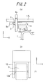
- Fig. 2 (a) illustrates a partially enlarged view of the tire surface printing device of Fig. 1 .
- Fig. 2 (b) is a side view as viewed from the arrow A-A in Fig. 2 (a) .
- Fig. 1 is a schematic diagram of a tire surface printing device that performs a method for printing onto a tire surface according to one embodiment.
- Fig. 2 (a) illustrates a partially enlarged view of the tire surface printing device of Fig. 1 .
- Fig. 2 (b) is a side view as viewed from the arrow A-A in Fig. 2 (a) .
- Fig. 1 is a schematic diagram of a tire surface printing device that performs a method for printing onto a tire surface according to one embodiment.
- Fig. 2 (a) illustrates a partially enlarged view of the tire
- the symbol X refers to a width direction of the tire to be printed onto
- the symbol Y refers to a radial direction of the tire
- the symbol Z refers to a circumferential direction of the tire
- the symbol Z1 refers to an axis line along the circumferential direction Z.
- the tire printing device shown in Fig.1 includes at least one (two in the illustrated embodiment) printer heads 3, 4 that eject and apply the coating material onto a tire surface (side wall), widthwise moving units 6, 7 that move the printer heads 3, 4 along the axis direction (width direction) X of the tire T, radial moving units 9, 10 in conjunction with the widthwise moving units 6, 7 that move the printer heads 3, 4 along the radial direction Y of the tire T, and swinging units 12, 13 that swing the printer heads 3, 4 around the axis line Z1 extending along the circumferential direction Z of the tire T.
- the printer heads 3, 4 are an inkjet type, but may also be an air spray type, or an airless spray type. Furthermore, as shown in this embodiment, when multi-color printing is performed under simultaneous rotations, a plurality of printer heads 3, 4 may be arranged depending on the number of applying colors.
- the widthwise moving units 6, 7 and the radial direction moving units 9, 10 utilize a feed screw mechanism in this embodiment.
- the feed screw mechanism includes ball screws (not shown in the figures), servo motors 6a, 7a, 9a, 10a that rotate the ball screws, sliders (not shown in the figures) that are screwed together with the ball screws to move printer head 3, 4, and position detectors (not shown in the figures).
- the displacements of the servo motors 6a, 7a, 9a, 10a are detected by the position detectors, and the detected positions are transmitted to a PC (personal computer) 15 which acts as a control device.
- PC personal computer
- the movement mechanisms of the moving units are not particularly limited.
- a hydraulic cylinder may be utilized to move the printer heads 3, 4.
- the radial moving units 9, 10 are supported by a beam unit 17b of a frame 17 formed with a pillar unit 17a and the beam unit 17b.
- the widthwise moving units 6, 7 are supported by the slider of the radial moving units 9, 10 so that the widthwise moving units 6, 7 are movable in the radial direction Y.
- the swinging unit 12 representing the swinging units 12, 13 in Fig. 2 (a) and Fig. 2 (b) includes a swinging shaft 12a connected to the printer head 3, the servo motor, in cooperation with the printer head 3, for swinging the swinging shaft 12a around the axis Z1, and a swinging angle detector (not shown in the figures) for detecting a swinging angle of the swinging shaft 12a.
- the swinging angle detected by the swinging angle detector is transmitted to the PC 15.
- a hydraulic cylinder, a piezoelectric element or the like may be utilized to swing the printer heads 3, 4 around the axis Z1.
- the tire printing device 1 includes an upper rim 19 and a lower rim 20 both are fitted to bead portions B of the tire T to hold the tire T, a tire rotation main shaft 22 connected to the upper rim 19, a slave shaft 24 connected to the lower rim, a rotation main shaft-driving device 26 that rotates the tire rotation main shaft 22.
- the tire T on the tire printing device 1 is rotated by the tire rotation main shaft 22.
- an inside of the slave shaft 24 is formed with an air inlet 28 for compressed air provided at the lower end of the slave shaft 24 and a communication passage 24a that communicates with the interior of the tire.
- the tire printing device 1 is configured to be capable of letting air in and out to the inside of the tire through the communication passage 24a.
- the reference numeral 29 in Fig. 1 denotes a shaft bearing that supports the slave shaft 24
- the reference numeral 30 denotes an elevator unit that moves along a rail 31 provided on the pillar unit 17a of the frame 17 and that moves the shaft bearing 29 and the slave shaft 24 up and down.
- the PC 15 is provided with a rotation control means 33, a moving unit control means 34, a swinging unit control means 35 and a print control means 36.
- the rotation control means 33 is connected to the rotation main shaft-driving device 26 and controls the rotation main shaft-driving device 26 so that the tire T rotates at a constant velocity.
- the moving unit control means 34 is connected to the widthwise moving units 6, 7 and radial moving units 9, 10 and respectively controls the widthwise moving units 6, 7 and radial moving units 9, 10 so that the printer heads 3, 4 are positioned at predetermined positions on the tire side wall.
- the swinging unit control means 35 is connected to the swinging units 12, 13 and controls the swinging units 12, 13 so that the printer heads 3, 4 are positioned at predetermined angles (substantially parallel) with respect to the curved surface of the tire side wall.
- the print control means 36 is connected to the printer heads 3, 4 and outputs print control signals and print data signals to the printer heads 3, 4.
- each of the rotation control means 33, the moving unit control means 34, the swinging unit control means 35 and the print control means 36 are realized by executing a software (program) stored in the PC 15.
- the information regarding the shape of the tire T may be input into the PC 15 in advance or data read by a scanner provided for scanning the outline of the tire side wall (curved surface) may be input into the PC 15.
- a method for printing characters and patterns onto a surface (side wall surface) of the tire T by using the tire printing device 1 of the present embodiment is described as follows. First, a vulcanized tire T is mounted onto an upper rim 19 and a lower rim 20 (rim mount process); the tire T mounted on the rims is installed onto the tire printing device 1 (tire installation process); and an internal pressure is applied into the tire T through an air inlet 28 to inflate the tire T (tire inflation process). At this time, there is no particular limitation for the internal pressure to be filled into the tire T. However, in order to have the curvature of the tire side wall during printing be equivalent to the curvature of the tire side wall when the tire is in use, a regular internal pressure is preferred.
- the regular internal pressure refers to "the maximum air pressure" as defined by JATMA, the maximum value of TIRE LOAD LIMITS AT VARIOUS COLD INFLATION PRESSURES as defined by TRA, or the INFLATION PRESSURES as defined by ETRTO.
- the rotation main shaft 22 is driven through the rotation main shaft-driving device 26 to rotate the tire T (tire rotation process).
- the widthwise moving units 6, 7 and radial moving units 9, 10 are driven to move the printer heads 3, 4 along the tire width direction X and the tire radial direction Y, thereby positioning the printer heads 3, 4 onto the predetermined positions on the side wall of the tire T, and the swinging units 12, 13 are driven to adjust the distance and posture of the printer heads 3, 4 with respect to the side surface of the tire T to be constant (printer heads position and posture adjustment process).
- the coating material are ejected and applied from the printer heads 3, 4 onto the side wall of the rotating tire T while maintaining the distance and posture of the printer heads 3, 4 to be constant with respect to the side wall of the tire T to draw (print) desired characters, patterns, symbols, designs (predetermined patterns) or the like (print process).
- the coating material applied on the side wall of the tire T is dried and hardened by UV lamps (not shown in figures) placed adjacent to the printer heads 3, 4 (dry process). It should be noted that the above mentioned tire rotation process can be reversed with the printer heads position and posture adjustment process in order.
- the printer heads 3, 4 placed near the rotating tire T are swung around the axis Z1 along the circumferential direction Z of the tire T while the printer heads 3, 4 are moved along the width direction X and the radial direction Y of the tire T during the printing, so that, as shown in Fig. 3 , the constant (appropriate) distance and posture of the printer heads 3, 4 with respect to the tire T side surface can be maintained.
- the coating material ejected from the printing heads 3, 4 can be applied on the side wall of the tire T without being diffused.
- characters, patterns or the like can be printed clearly without blurring.
- the cumbersome operations involved in the prior art such as flattening the surface to be printed by pressing the side wall of the tire T with a roller can be eliminated.
- the tire surface printing device 1 and the method for tire surface printing of the present embodiment have a plurality sets of printer heads 3, 4, so that multi-color printing may be performed under simultaneous rotations.
- the distance and the posture of the printer heads 3, 4 with respect to the side wall of the tire T are controlled by a program, which allows characters, patterns or the like to be printed automatically onto a predetermined position on the side wall of the tire T after the tire T is installed onto the tire printing device 1.
- the tire surface printing device 1 and the method for tire surface printing of the present embodiment since the printing onto the side wall of the tire T by the printer heads 3, 4 is performed under the state that the tire T is mounted on the rims and filled with the internal pressure, the tire T can be maintained with a constant shape during printing. As a result, the printing of the characters, the patterns or the like onto the curved surface on the side wall of the tire T can be performed without any wrinkles and blurring.
- the printing is performed under a state that the tire T is filled with the internal pressure, the curvature of the side wall of the tire T during printing can be approximated with the curvature of the side wall of the tire T when in use (when the tire T is mounted onto a regular rim and filled with a regular internal pressure). Therefore, the appearance of the visible characters, patterns or the like can be improved when the tire is in use. From this viewpoint, the printing is preferably performed when the tire T is filled with the regular internal pressure.
- a pneumatic tire is used as the tire to be printed onto, however, the present invention can also be applied onto a solid tire.
- two printer heads have been shown by way of example, however, one printer head or three or more printer heads may be provided.
- the internal pressure may be lower than the regular internal pressure when the printing is performed with an internal pressure filled inside the tire.
Landscapes
- Engineering & Computer Science (AREA)
- Mechanical Engineering (AREA)
- Manufacturing & Machinery (AREA)
- Tyre Moulding (AREA)
- Tires In General (AREA)
- Application Of Or Painting With Fluid Materials (AREA)
Abstract
Description
- The present invention relates to a tire printing device and a method for printing characters, patterns or the like on a tire surface.
- As a printing device for printing characters, patterns or the like on a tire surface, a swiveling type tire printer as disclosed in Patent Literature 1 is conventionally known. The swiveling type tire printer has a function of adjusting its center position, height, and turning radius according to the size of the tire fixed to a base, and prints characters and patterns while swiveling above a tire sidewall with a strut extending along the center of the tire as a rotational axis.
- However, the tire sidewall is curved rather than flat, so that the position and posture of the printer head described in Patent Literature 1 with respect to the tire surface may differ depending on the position on the sidewall of the tire. In other words, as shown in
Fig. 4 , the distance between the sidewall of the tire T and aprinter head 103 becomes minimum at a maximum width position on the sidewall, and becomes larger as further away from the maximum width position of the sidewall. Therefore, at the position where the distance between the tire side surface T and theprinter head 103 becomes excessively large, the ink ejected from theprinter head 103 is diffused to make characters, patterns or the like blurry. In addition, since the printer described in Patent Literature 1 swivels the printer head along the sidewall, the radius of swivel and the height of the printer described in Patent Literature 1 need to be adjusted each time when the tire size is changed. The operations thus become complicated. - These problems can be solved by using an ink-jet head to perform the printing on a rotating tire while the sidewall is pressed by a roller to flatten the surface to be printed as described in Patent Literature 2. However, after the printing is performed under a state that the side wall is pressed by a roller to flatten the surface to be printed, and when an internal pressure is applied to the tire and the tire side wall becomes curved (e.g. when the tire is used), the characters and patterns are stretched. As a result, the characters and patterns become distorted which impairs the appearance. In addition, since the sidewall must be pressed evenly by the roller according to the technique described in Patent Literature 2, the operations are complicated.
-
- PTL 1:
JP2006111242 - PTL 2:
JP2010125440 - Therefore, in order to solve the above mentioned problems, the purpose of the present invention is to provide a tire printing device and a tire surface printing method that are capable of printing characters, patterns or the like clearly onto a tire surface without complicated operations.
- The present invention is intended to address the above-mentioned problems. The tire printing device of the present invention includes a printer head that ejects and applies a coating material onto a tire surface, a widthwise moving unit that moves the printer head along a width direction of the tire, a radial moving unit that moves the printer head along a radial direction of the tire, and a swinging unit that swings the printer head around an axis along a circumferential direction of the tire.
- The tire printing device of the present invention preferably contains a plurality of printer heads.
- In order to solve the above mentioned problems, a method for printing onto a tire surface of the present invention ejects and applies a coating material from a printer head to the rotating tire surface, wherein during the printing, the printer head is swung around an axis along a circumferential direction of the tire while the printer head is moved along a width direction and the radial direction of the tire so as to maintain a constant distance and posture of the printer head with respect to the tire surface.
- In addition, according to the method for printing onto a tire surface of the present invention, the distance and posture of the printer head with respect to the tire surface is preferably controlled by a program.
- In addition, according to the method for printing onto a tire surface of the present invention, the printing onto the tire surface by the printer head is preferably performed under a state that the tire is mounted on a rim and an internal pressure is applied to the tire mounted on the rim.
- According to the tire printing device and tire surface printing method of the present invention, during the printing, the printer head is swung around the axis along the circumferential direction of the tire while the printer head is moved along the width direction and the radial direction of the tire so as to maintain an appropriate distance and posture of the printer head with respect to the tire surface. Therefore, the coating material ejected from the printer head can be applied onto the tire surface without being diffused. As a result, not only the characters and patterns can be printed clearly without blurring but also cumbersome operations in the prior art, such as flattening the tire surface with the pressing roller, can be eliminated.
-
-
Fig. 1 is a schematic diagram of a tire printing device that performs a method for printing onto a tire surface according to embodiments of the present invention.Fig. 2 (a) illustrates a partially enlarged view of the tire printing device ofFig. 1 .Fig. 2 (b) is a side view as viewed from the arrow A-A inFig. 2 (a) .Fig. 3 illustrates a schematic diagram showing the position and posture of the printer head with respect to the tire surface when the tire printing device ofFig. 1 prints onto the side wall of the tire.Fig. 4 illustrates a schematic diagram showing a position and posture of the printer head with respect to the tire surface when a conventional tire printing device prints onto the side wall of the tire. - Embodiments of the present invention are described below with reference to the drawings.
Fig. 1 is a schematic diagram of a tire surface printing device that performs a method for printing onto a tire surface according to one embodiment.Fig. 2 (a) illustrates a partially enlarged view of the tire surface printing device ofFig. 1 .Fig. 2 (b) is a side view as viewed from the arrow A-A inFig. 2 (a) . InFig. 2 (b) , the symbol X refers to a width direction of the tire to be printed onto, the symbol Y refers to a radial direction of the tire, the symbol Z refers to a circumferential direction of the tire, and the symbol Z1 refers to an axis line along the circumferential direction Z. - The tire printing device shown in
Fig.1 includes at least one (two in the illustrated embodiment)printer heads units 6, 7 that move theprinter heads units units 6, 7 that move theprinter heads units printer heads - The
printer heads printer heads - The widthwise moving
units 6, 7 and the radialdirection moving units servo motors printer head servo motors units 6, 7 and the radialdirection moving units printer heads printer heads units beam unit 17b of aframe 17 formed with apillar unit 17a and thebeam unit 17b. The widthwise movingunits 6, 7 are supported by the slider of the radial movingunits units 6, 7 are movable in the radial direction Y. - The swinging
unit 12 representing theswinging units Fig. 2 (a) and Fig. 2 (b) includes a swingingshaft 12a connected to theprinter head 3, the servo motor, in cooperation with theprinter head 3, for swinging the swingingshaft 12a around the axis Z1, and a swinging angle detector (not shown in the figures) for detecting a swinging angle of the swingingshaft 12a. The swinging angle detected by the swinging angle detector is transmitted to the PC 15. It should be noted that instead of the servo motor, a hydraulic cylinder, a piezoelectric element or the like may be utilized to swing theprinter heads - In addition, the tire printing device 1 includes an
upper rim 19 and alower rim 20 both are fitted to bead portions B of the tire T to hold the tire T, a tire rotationmain shaft 22 connected to theupper rim 19, aslave shaft 24 connected to the lower rim, a rotation main shaft-driving device 26 that rotates the tire rotationmain shaft 22. The tire T on the tire printing device 1 is rotated by the tire rotationmain shaft 22. In addition, an inside of theslave shaft 24 is formed with anair inlet 28 for compressed air provided at the lower end of theslave shaft 24 and acommunication passage 24a that communicates with the interior of the tire. In other words, the tire printing device 1 is configured to be capable of letting air in and out to the inside of the tire through thecommunication passage 24a. In addition, thereference numeral 29 inFig. 1 denotes a shaft bearing that supports theslave shaft 24, thereference numeral 30 denotes an elevator unit that moves along arail 31 provided on thepillar unit 17a of theframe 17 and that moves the shaft bearing 29 and theslave shaft 24 up and down. - The PC 15 is provided with a rotation control means 33, a moving unit control means 34, a swinging unit control means 35 and a print control means 36. The rotation control means 33 is connected to the rotation main shaft-
driving device 26 and controls the rotation main shaft-driving device 26 so that the tire T rotates at a constant velocity. The moving unit control means 34 is connected to the widthwise movingunits 6, 7 and radial movingunits units 6, 7 and radial movingunits printer heads units units printer heads printer heads printer heads - It should be noted that the functions of each of the rotation control means 33, the moving unit control means 34, the swinging unit control means 35 and the print control means 36 are realized by executing a software (program) stored in the PC 15. The information regarding the shape of the tire T may be input into the PC 15 in advance or data read by a scanner provided for scanning the outline of the tire side wall (curved surface) may be input into the PC 15.
- A method for printing characters and patterns onto a surface (side wall surface) of the tire T by using the tire printing device 1 of the present embodiment is described as follows. First, a vulcanized tire T is mounted onto an
upper rim 19 and a lower rim 20 (rim mount process); the tire T mounted on the rims is installed onto the tire printing device 1 (tire installation process); and an internal pressure is applied into the tire T through anair inlet 28 to inflate the tire T (tire inflation process). At this time, there is no particular limitation for the internal pressure to be filled into the tire T. However, in order to have the curvature of the tire side wall during printing be equivalent to the curvature of the tire side wall when the tire is in use, a regular internal pressure is preferred. The regular internal pressure refers to "the maximum air pressure" as defined by JATMA, the maximum value of TIRE LOAD LIMITS AT VARIOUS COLD INFLATION PRESSURES as defined by TRA, or the INFLATION PRESSURES as defined by ETRTO. - Next, the rotation
main shaft 22 is driven through the rotation main shaft-drivingdevice 26 to rotate the tire T (tire rotation process). Next, the widthwise movingunits 6, 7 andradial moving units units - Therefore, according to the tire surface printing device 1 and the method for tire surface printing, the printer heads 3, 4 placed near the rotating tire T are swung around the axis Z1 along the circumferential direction Z of the tire T while the printer heads 3, 4 are moved along the width direction X and the radial direction Y of the tire T during the printing, so that, as shown in
Fig. 3 , the constant (appropriate) distance and posture of the printer heads 3, 4 with respect to the tire T side surface can be maintained. Thereby, the coating material ejected from the printing heads 3, 4 can be applied on the side wall of the tire T without being diffused. As a result, characters, patterns or the like can be printed clearly without blurring. In addition, the cumbersome operations involved in the prior art, such as flattening the surface to be printed by pressing the side wall of the tire T with a roller can be eliminated. - In addition, the tire surface printing device 1 and the method for tire surface printing of the present embodiment have a plurality sets of printer heads 3, 4, so that multi-color printing may be performed under simultaneous rotations.
- According to the tire surface printing device 1 and the method for tire surface printing of the present embodiment, the distance and the posture of the printer heads 3, 4 with respect to the side wall of the tire T are controlled by a program, which allows characters, patterns or the like to be printed automatically onto a predetermined position on the side wall of the tire T after the tire T is installed onto the tire printing device 1.
- In addition, according to the tire surface printing device 1 and the method for tire surface printing of the present embodiment, since the printing onto the side wall of the tire T by the printer heads 3, 4 is performed under the state that the tire T is mounted on the rims and filled with the internal pressure, the tire T can be maintained with a constant shape during printing. As a result, the printing of the characters, the patterns or the like onto the curved surface on the side wall of the tire T can be performed without any wrinkles and blurring. Furthermore, since the printing is performed under a state that the tire T is filled with the internal pressure, the curvature of the side wall of the tire T during printing can be approximated with the curvature of the side wall of the tire T when in use (when the tire T is mounted onto a regular rim and filled with a regular internal pressure). Therefore, the appearance of the visible characters, patterns or the like can be improved when the tire is in use. From this viewpoint, the printing is preferably performed when the tire T is filled with the regular internal pressure.
- The foregoing has described with reference to the illustrated examples. However, the present invention is not limited to the embodiments described above. The present invention can be modified accordingly within the scope of the appended claims. For example, in the above mentioned embodiments, a pneumatic tire is used as the tire to be printed onto, however, the present invention can also be applied onto a solid tire. In the above mentioned embodiments, two printer heads have been shown by way of example, however, one printer head or three or more printer heads may be provided. In addition, the internal pressure may be lower than the regular internal pressure when the printing is performed with an internal pressure filled inside the tire.
- In conclusion, it is possible to provide a tire surface printing device and a method for printing onto a tire surface that are capable of printing the characters, patterns or the like clearly onto the tire surface without cumbersome operations.
-
- 1:
- Tire surface printing device
- 3, 4:
- Printer head
- 6, 7:
- Widthwise moving units
- 9, 10:
- Radial moving units
- 12, 13:
- Swinging units
- 12a:
- Swinging shaft
- 15:
- PC
- 17:
- Frame
- 19:
- Upper rim
- 20:
- Lower rim
- 26:
- Rotation main shaft-driving device
- 28:
- Air inlet
- T:
- Tire to be printed
Claims (5)
- A tire printing device comprising:a printer head that ejects and applies a coating material onto a tire surface,a widthwise moving unit that moves the printer head along a width direction of the tire,a radial moving unit that moves the printer head along a radial direction of the tire, anda swinging unit that swings the printer head around an axis along a circumferential direction of the tire.
- The tire printing device according to claim 1, wherein a plurality of the printer heads are provided.
- A method for printing onto a tire surface by ejecting and applying a coating material from a printer head to the rotating tire surface, wherein
during the printing, the printer head is swung around an axis along a circumferential direction of the tire while the printer head is moved along a width direction and the radial direction of the tire so as to maintain a constant distance and posture of the printer head with respect to the tire surface. - The method for printing onto a tire surface according to claim 3, wherein the distance and posture of the printer head with respect to the tire surface is controlled by a program.
- The method for printing onto a tire surface according to claim 3 or 4, wherein the printing onto the tire surface by the printer head is performed under a state that the tire is mounted on a rim and an internal pressure is applied to the tire mounted on the rim.
Applications Claiming Priority (2)
| Application Number | Priority Date | Filing Date | Title |
|---|---|---|---|
| JP2011053279A JP5749946B2 (en) | 2011-03-10 | 2011-03-10 | Tire printing apparatus and tire surface printing method |
| PCT/JP2012/001166 WO2012120803A1 (en) | 2011-03-10 | 2012-02-21 | Tire printing device and tire surface printing method |
Publications (3)
| Publication Number | Publication Date |
|---|---|
| EP2684682A1 true EP2684682A1 (en) | 2014-01-15 |
| EP2684682A4 EP2684682A4 (en) | 2014-08-20 |
| EP2684682B1 EP2684682B1 (en) | 2015-09-16 |
Family
ID=46797779
Family Applications (1)
| Application Number | Title | Priority Date | Filing Date |
|---|---|---|---|
| EP12754592.9A Active EP2684682B1 (en) | 2011-03-10 | 2012-02-21 | Tire printing device and tire surface printing method |
Country Status (5)
| Country | Link |
|---|---|
| US (1) | US9039139B2 (en) |
| EP (1) | EP2684682B1 (en) |
| JP (1) | JP5749946B2 (en) |
| CN (1) | CN103402744B (en) |
| WO (1) | WO2012120803A1 (en) |
Cited By (2)
| Publication number | Priority date | Publication date | Assignee | Title |
|---|---|---|---|---|
| EP2772314A1 (en) * | 2013-03-01 | 2014-09-03 | Büchel GmbH & Co. Fahrzeugteilefabrik KG | Method and apparatus for applying a coating to a raw wheel rim profile |
| EP3381669A1 (en) * | 2017-03-30 | 2018-10-03 | Continental Reifen Deutschland GmbH | Method for typification of a vehicle tyre and production unit for performing the method |
Families Citing this family (17)
| Publication number | Priority date | Publication date | Assignee | Title |
|---|---|---|---|---|
| CN103587269B (en) * | 2013-11-18 | 2015-10-28 | 湖北久瑞核技术股份有限公司 | A kind of processing method of tire sidewall multicolour pattern and production line thereof |
| CN104228355B (en) * | 2014-08-20 | 2016-11-23 | 武汉大学 | A kind of color tyre printer and Method of printing |
| CN104176677B (en) * | 2014-08-25 | 2016-08-24 | 合肥汉闻数字印刷设备有限公司 | A kind of automatic rising-sinking platform for tire digital printer |
| CN104191828B (en) * | 2014-08-28 | 2017-03-08 | 合肥海闻自动化设备有限公司 | A kind of moveable platform structure for tire digital printer |
| CN104260559B (en) * | 2014-09-10 | 2016-08-31 | 合肥汉闻数字印刷设备有限公司 | A kind of rotational structure for tire digital printer |
| CN104354477B (en) * | 2014-09-24 | 2016-07-13 | 合肥汉闻数字印刷设备有限公司 | A kind of removable nozzle system for tire digital printer |
| CN104260560A (en) * | 2014-09-27 | 2015-01-07 | 合肥海闻自动化设备有限公司 | Numeric printer for printing tire |
| CN104260562B (en) * | 2014-10-01 | 2016-03-23 | 合肥海闻自动化设备有限公司 | A kind of tire fixture for tire digital printer |
| CN104309307A (en) * | 2014-10-02 | 2015-01-28 | 合肥海闻自动化设备有限公司 | Ink circulating system for tire digital printer |
| WO2016109012A1 (en) | 2014-12-31 | 2016-07-07 | Bridgestone Americas Tire Operations, Llc | Methods and apparatuses for additively manufacturing rubber |
| CN104786689A (en) * | 2015-04-07 | 2015-07-22 | 无锡三页书国际贸易有限公司 | Manufacturing method of colored and dazzling tire |
| CN104786669B (en) * | 2015-04-07 | 2016-08-24 | 无锡三页书国际贸易有限公司 | A kind of device dazzling driving wheel tire for manufacturing colour |
| US20170253024A1 (en) * | 2016-03-03 | 2017-09-07 | Inx International Ink Co. | Apparatus and method for printing on non-cylindrical surfaces having circular symmetry |
| US10717321B2 (en) * | 2017-03-13 | 2020-07-21 | Shimano Inc. | Bicycle rim, bicycle rim printing apparatus, and printing method of printing non-contact printed deposit on annular rim body |
| FR3086199B1 (en) * | 2018-09-24 | 2020-12-18 | Michelin & Cie | PROCESS FOR MARKING A TIRE, IN PARTICULAR BY COLOR PRINTING |
| FR3097166B1 (en) * | 2019-06-13 | 2021-11-19 | Michelin & Cie | Process for depositing a colored and pneumatic layer |
| CN115415073A (en) * | 2022-08-18 | 2022-12-02 | 天津万达轮胎有限公司 | Color line repairing device |
Family Cites Families (11)
| Publication number | Priority date | Publication date | Assignee | Title |
|---|---|---|---|---|
| US4308747A (en) | 1980-03-27 | 1982-01-05 | The B. F. Goodrich Company | Apparatus for marking radial first harmonic high point on a tire |
| JPS5993343A (en) * | 1982-11-19 | 1984-05-29 | Yokohama Rubber Co Ltd:The | Marking device for tire |
| CA1255515A (en) | 1985-12-18 | 1989-06-13 | Nick M. Miller, Iii | Tire marker |
| IT1289701B1 (en) * | 1996-11-29 | 1998-10-16 | Bridgestone Firestone Tech | METHOD FOR MARKING A TIRE |
| US6578276B2 (en) | 1998-01-27 | 2003-06-17 | Eastman Kodak Company | Apparatus and method for marking multiple colors on a contoured surface having a complex topography |
| KR100342420B1 (en) | 1999-10-15 | 2002-07-04 | 조충환 | Printing equipment for bar code of a tire |
| EP1727666A1 (en) * | 2003-12-12 | 2006-12-06 | Pirelli Tyre S.p.A. | Process for manufacturing a tyre comprising the step of marking a structural element thereof |
| JP2006111242A (en) * | 2004-10-13 | 2006-04-27 | Teishin Kogyo Kk | Turning type tire printer |
| US7295948B2 (en) | 2005-01-15 | 2007-11-13 | Jetter Heinz L | Laser system for marking tires |
| WO2007071272A1 (en) * | 2005-12-21 | 2007-06-28 | Pirelli Tyre S.P.A. | Tire having a colored surface |
| JP5346565B2 (en) | 2008-12-01 | 2013-11-20 | 株式会社ブリヂストン | Inkjet printing device for donut type (ring type) articles |
-
2011
- 2011-03-10 JP JP2011053279A patent/JP5749946B2/en active Active
-
2012
- 2012-02-21 WO PCT/JP2012/001166 patent/WO2012120803A1/en not_active Ceased
- 2012-02-21 EP EP12754592.9A patent/EP2684682B1/en active Active
- 2012-02-21 US US14/004,000 patent/US9039139B2/en active Active
- 2012-02-21 CN CN201280011469.4A patent/CN103402744B/en active Active
Cited By (2)
| Publication number | Priority date | Publication date | Assignee | Title |
|---|---|---|---|---|
| EP2772314A1 (en) * | 2013-03-01 | 2014-09-03 | Büchel GmbH & Co. Fahrzeugteilefabrik KG | Method and apparatus for applying a coating to a raw wheel rim profile |
| EP3381669A1 (en) * | 2017-03-30 | 2018-10-03 | Continental Reifen Deutschland GmbH | Method for typification of a vehicle tyre and production unit for performing the method |
Also Published As
| Publication number | Publication date |
|---|---|
| EP2684682B1 (en) | 2015-09-16 |
| EP2684682A4 (en) | 2014-08-20 |
| US20140022302A1 (en) | 2014-01-23 |
| CN103402744A (en) | 2013-11-20 |
| JP2012187816A (en) | 2012-10-04 |
| US9039139B2 (en) | 2015-05-26 |
| JP5749946B2 (en) | 2015-07-15 |
| WO2012120803A1 (en) | 2012-09-13 |
| CN103402744B (en) | 2015-09-23 |
Similar Documents
| Publication | Publication Date | Title |
|---|---|---|
| EP2684682B1 (en) | Tire printing device and tire surface printing method | |
| CN108495752B (en) | An inkjet printing device and printing method | |
| EP2409846B1 (en) | Inkjet recording apparatus | |
| EP2385009B1 (en) | Inkjet printer | |
| EP2639053B1 (en) | Tire surface printing method | |
| EP2638979B1 (en) | Printing device | |
| US9162503B2 (en) | Machine for printing an object with tiltable inkjet printing heads | |
| CN104118212B (en) | A kind of inkjet-printing device and inkjet printing methods | |
| EP2792474A1 (en) | Tire printing method and tire printing device | |
| CN106183416A (en) | A kind of inkjet-printing device | |
| CN205467943U (en) | Ink -jet printing device | |
| JP6492433B2 (en) | Recording apparatus and recording method | |
| JP2013224055A (en) | Tire holder, tire printing method, and tire printer | |
| JP5886679B2 (en) | Tire printing apparatus and tire printing method | |
| JP5894458B2 (en) | Tire printing equipment | |
| JP5800701B2 (en) | Tire printing method and tire printing apparatus | |
| JP5580234B2 (en) | Tire printing equipment | |
| JP5952003B2 (en) | Tire printing equipment | |
| CN223559326U (en) | An inkjet printer | |
| CN223559327U (en) | Ink-jet printer | |
| JP2012192742A (en) | Method of printing tire surface, and printer for tire | |
| JP5986964B2 (en) | Tire surface printing method and tire surface printing apparatus | |
| JP2012131508A (en) | Method of printing on surface of tire | |
| JP2017132177A (en) | Printer and printer control method | |
| CN107914478A (en) | A kind of positive and negative stamp digital inkjet printing machine of circle fabric and printing method |
Legal Events
| Date | Code | Title | Description |
|---|---|---|---|
| PUAI | Public reference made under article 153(3) epc to a published international application that has entered the european phase |
Free format text: ORIGINAL CODE: 0009012 |
|
| 17P | Request for examination filed |
Effective date: 20130821 |
|
| AK | Designated contracting states |
Kind code of ref document: A1 Designated state(s): AL AT BE BG CH CY CZ DE DK EE ES FI FR GB GR HR HU IE IS IT LI LT LU LV MC MK MT NL NO PL PT RO RS SE SI SK SM TR |
|
| DAX | Request for extension of the european patent (deleted) | ||
| A4 | Supplementary search report drawn up and despatched |
Effective date: 20140721 |
|
| RIC1 | Information provided on ipc code assigned before grant |
Ipc: B41J 3/407 20060101ALN20140715BHEP Ipc: B05B 13/04 20060101ALI20140715BHEP Ipc: B29D 30/72 20060101AFI20140715BHEP Ipc: B05D 7/00 20060101ALI20140715BHEP Ipc: B05D 7/02 20060101ALI20140715BHEP Ipc: B41M 5/00 20060101ALN20140715BHEP |
|
| GRAP | Despatch of communication of intention to grant a patent |
Free format text: ORIGINAL CODE: EPIDOSNIGR1 |
|
| RIC1 | Information provided on ipc code assigned before grant |
Ipc: B41M 5/00 20060101ALN20150317BHEP Ipc: B05D 7/00 20060101ALI20150317BHEP Ipc: B41J 3/407 20060101ALN20150317BHEP Ipc: B05B 13/04 20060101ALI20150317BHEP Ipc: B29D 30/72 20060101AFI20150317BHEP Ipc: B05D 7/02 20060101ALI20150317BHEP |
|
| INTG | Intention to grant announced |
Effective date: 20150401 |
|
| GRAS | Grant fee paid |
Free format text: ORIGINAL CODE: EPIDOSNIGR3 |
|
| GRAA | (expected) grant |
Free format text: ORIGINAL CODE: 0009210 |
|
| AK | Designated contracting states |
Kind code of ref document: B1 Designated state(s): AL AT BE BG CH CY CZ DE DK EE ES FI FR GB GR HR HU IE IS IT LI LT LU LV MC MK MT NL NO PL PT RO RS SE SI SK SM TR |
|
| REG | Reference to a national code |
Ref country code: GB Ref legal event code: FG4D |
|
| REG | Reference to a national code |
Ref country code: CH Ref legal event code: EP |
|
| REG | Reference to a national code |
Ref country code: IE Ref legal event code: FG4D |
|
| REG | Reference to a national code |
Ref country code: AT Ref legal event code: REF Ref document number: 749455 Country of ref document: AT Kind code of ref document: T Effective date: 20151015 |
|
| REG | Reference to a national code |
Ref country code: DE Ref legal event code: R096 Ref document number: 602012010731 Country of ref document: DE |
|
| REG | Reference to a national code |
Ref country code: NL Ref legal event code: MP Effective date: 20150916 |
|
| REG | Reference to a national code |
Ref country code: FR Ref legal event code: PLFP Year of fee payment: 5 |
|
| PG25 | Lapsed in a contracting state [announced via postgrant information from national office to epo] |
Ref country code: GR Free format text: LAPSE BECAUSE OF FAILURE TO SUBMIT A TRANSLATION OF THE DESCRIPTION OR TO PAY THE FEE WITHIN THE PRESCRIBED TIME-LIMIT Effective date: 20151217 Ref country code: LT Free format text: LAPSE BECAUSE OF FAILURE TO SUBMIT A TRANSLATION OF THE DESCRIPTION OR TO PAY THE FEE WITHIN THE PRESCRIBED TIME-LIMIT Effective date: 20150916 Ref country code: FI Free format text: LAPSE BECAUSE OF FAILURE TO SUBMIT A TRANSLATION OF THE DESCRIPTION OR TO PAY THE FEE WITHIN THE PRESCRIBED TIME-LIMIT Effective date: 20150916 Ref country code: LV Free format text: LAPSE BECAUSE OF FAILURE TO SUBMIT A TRANSLATION OF THE DESCRIPTION OR TO PAY THE FEE WITHIN THE PRESCRIBED TIME-LIMIT Effective date: 20150916 Ref country code: NO Free format text: LAPSE BECAUSE OF FAILURE TO SUBMIT A TRANSLATION OF THE DESCRIPTION OR TO PAY THE FEE WITHIN THE PRESCRIBED TIME-LIMIT Effective date: 20151216 |
|
| REG | Reference to a national code |
Ref country code: LT Ref legal event code: MG4D |
|
| REG | Reference to a national code |
Ref country code: AT Ref legal event code: MK05 Ref document number: 749455 Country of ref document: AT Kind code of ref document: T Effective date: 20150916 |
|
| PG25 | Lapsed in a contracting state [announced via postgrant information from national office to epo] |
Ref country code: HR Free format text: LAPSE BECAUSE OF FAILURE TO SUBMIT A TRANSLATION OF THE DESCRIPTION OR TO PAY THE FEE WITHIN THE PRESCRIBED TIME-LIMIT Effective date: 20150916 Ref country code: RS Free format text: LAPSE BECAUSE OF FAILURE TO SUBMIT A TRANSLATION OF THE DESCRIPTION OR TO PAY THE FEE WITHIN THE PRESCRIBED TIME-LIMIT Effective date: 20150916 Ref country code: SE Free format text: LAPSE BECAUSE OF FAILURE TO SUBMIT A TRANSLATION OF THE DESCRIPTION OR TO PAY THE FEE WITHIN THE PRESCRIBED TIME-LIMIT Effective date: 20150916 |
|
| PG25 | Lapsed in a contracting state [announced via postgrant information from national office to epo] |
Ref country code: NL Free format text: LAPSE BECAUSE OF FAILURE TO SUBMIT A TRANSLATION OF THE DESCRIPTION OR TO PAY THE FEE WITHIN THE PRESCRIBED TIME-LIMIT Effective date: 20150916 |
|
| PG25 | Lapsed in a contracting state [announced via postgrant information from national office to epo] |
Ref country code: ES Free format text: LAPSE BECAUSE OF FAILURE TO SUBMIT A TRANSLATION OF THE DESCRIPTION OR TO PAY THE FEE WITHIN THE PRESCRIBED TIME-LIMIT Effective date: 20150916 Ref country code: CZ Free format text: LAPSE BECAUSE OF FAILURE TO SUBMIT A TRANSLATION OF THE DESCRIPTION OR TO PAY THE FEE WITHIN THE PRESCRIBED TIME-LIMIT Effective date: 20150916 Ref country code: EE Free format text: LAPSE BECAUSE OF FAILURE TO SUBMIT A TRANSLATION OF THE DESCRIPTION OR TO PAY THE FEE WITHIN THE PRESCRIBED TIME-LIMIT Effective date: 20150916 Ref country code: SK Free format text: LAPSE BECAUSE OF FAILURE TO SUBMIT A TRANSLATION OF THE DESCRIPTION OR TO PAY THE FEE WITHIN THE PRESCRIBED TIME-LIMIT Effective date: 20150916 Ref country code: IS Free format text: LAPSE BECAUSE OF FAILURE TO SUBMIT A TRANSLATION OF THE DESCRIPTION OR TO PAY THE FEE WITHIN THE PRESCRIBED TIME-LIMIT Effective date: 20160116 |
|
| PG25 | Lapsed in a contracting state [announced via postgrant information from national office to epo] |
Ref country code: BE Free format text: LAPSE BECAUSE OF NON-PAYMENT OF DUE FEES Effective date: 20160229 Ref country code: PL Free format text: LAPSE BECAUSE OF FAILURE TO SUBMIT A TRANSLATION OF THE DESCRIPTION OR TO PAY THE FEE WITHIN THE PRESCRIBED TIME-LIMIT Effective date: 20150916 Ref country code: PT Free format text: LAPSE BECAUSE OF FAILURE TO SUBMIT A TRANSLATION OF THE DESCRIPTION OR TO PAY THE FEE WITHIN THE PRESCRIBED TIME-LIMIT Effective date: 20160118 Ref country code: AT Free format text: LAPSE BECAUSE OF FAILURE TO SUBMIT A TRANSLATION OF THE DESCRIPTION OR TO PAY THE FEE WITHIN THE PRESCRIBED TIME-LIMIT Effective date: 20150916 Ref country code: RO Free format text: LAPSE BECAUSE OF FAILURE TO SUBMIT A TRANSLATION OF THE DESCRIPTION OR TO PAY THE FEE WITHIN THE PRESCRIBED TIME-LIMIT Effective date: 20150916 |
|
| REG | Reference to a national code |
Ref country code: DE Ref legal event code: R097 Ref document number: 602012010731 Country of ref document: DE |
|
| PLBE | No opposition filed within time limit |
Free format text: ORIGINAL CODE: 0009261 |
|
| STAA | Information on the status of an ep patent application or granted ep patent |
Free format text: STATUS: NO OPPOSITION FILED WITHIN TIME LIMIT |
|
| 26N | No opposition filed |
Effective date: 20160617 |
|
| PG25 | Lapsed in a contracting state [announced via postgrant information from national office to epo] |
Ref country code: DK Free format text: LAPSE BECAUSE OF FAILURE TO SUBMIT A TRANSLATION OF THE DESCRIPTION OR TO PAY THE FEE WITHIN THE PRESCRIBED TIME-LIMIT Effective date: 20150916 |
|
| PG25 | Lapsed in a contracting state [announced via postgrant information from national office to epo] |
Ref country code: MC Free format text: LAPSE BECAUSE OF FAILURE TO SUBMIT A TRANSLATION OF THE DESCRIPTION OR TO PAY THE FEE WITHIN THE PRESCRIBED TIME-LIMIT Effective date: 20150916 Ref country code: LU Free format text: LAPSE BECAUSE OF FAILURE TO SUBMIT A TRANSLATION OF THE DESCRIPTION OR TO PAY THE FEE WITHIN THE PRESCRIBED TIME-LIMIT Effective date: 20160221 |
|
| REG | Reference to a national code |
Ref country code: CH Ref legal event code: PL |
|
| GBPC | Gb: european patent ceased through non-payment of renewal fee |
Effective date: 20160221 |
|
| PG25 | Lapsed in a contracting state [announced via postgrant information from national office to epo] |
Ref country code: CH Free format text: LAPSE BECAUSE OF NON-PAYMENT OF DUE FEES Effective date: 20160229 Ref country code: LI Free format text: LAPSE BECAUSE OF NON-PAYMENT OF DUE FEES Effective date: 20160229 |
|
| PG25 | Lapsed in a contracting state [announced via postgrant information from national office to epo] |
Ref country code: SI Free format text: LAPSE BECAUSE OF FAILURE TO SUBMIT A TRANSLATION OF THE DESCRIPTION OR TO PAY THE FEE WITHIN THE PRESCRIBED TIME-LIMIT Effective date: 20150916 |
|
| REG | Reference to a national code |
Ref country code: IE Ref legal event code: MM4A |
|
| PG25 | Lapsed in a contracting state [announced via postgrant information from national office to epo] |
Ref country code: BE Free format text: LAPSE BECAUSE OF FAILURE TO SUBMIT A TRANSLATION OF THE DESCRIPTION OR TO PAY THE FEE WITHIN THE PRESCRIBED TIME-LIMIT Effective date: 20150916 |
|
| PG25 | Lapsed in a contracting state [announced via postgrant information from national office to epo] |
Ref country code: IE Free format text: LAPSE BECAUSE OF NON-PAYMENT OF DUE FEES Effective date: 20160221 Ref country code: GB Free format text: LAPSE BECAUSE OF NON-PAYMENT OF DUE FEES Effective date: 20160221 |
|
| REG | Reference to a national code |
Ref country code: FR Ref legal event code: PLFP Year of fee payment: 6 |
|
| PG25 | Lapsed in a contracting state [announced via postgrant information from national office to epo] |
Ref country code: MT Free format text: LAPSE BECAUSE OF FAILURE TO SUBMIT A TRANSLATION OF THE DESCRIPTION OR TO PAY THE FEE WITHIN THE PRESCRIBED TIME-LIMIT Effective date: 20150916 |
|
| REG | Reference to a national code |
Ref country code: FR Ref legal event code: PLFP Year of fee payment: 7 |
|
| PG25 | Lapsed in a contracting state [announced via postgrant information from national office to epo] |
Ref country code: SM Free format text: LAPSE BECAUSE OF FAILURE TO SUBMIT A TRANSLATION OF THE DESCRIPTION OR TO PAY THE FEE WITHIN THE PRESCRIBED TIME-LIMIT Effective date: 20150916 Ref country code: HU Free format text: LAPSE BECAUSE OF FAILURE TO SUBMIT A TRANSLATION OF THE DESCRIPTION OR TO PAY THE FEE WITHIN THE PRESCRIBED TIME-LIMIT; INVALID AB INITIO Effective date: 20120221 Ref country code: CY Free format text: LAPSE BECAUSE OF FAILURE TO SUBMIT A TRANSLATION OF THE DESCRIPTION OR TO PAY THE FEE WITHIN THE PRESCRIBED TIME-LIMIT Effective date: 20150916 |
|
| PG25 | Lapsed in a contracting state [announced via postgrant information from national office to epo] |
Ref country code: TR Free format text: LAPSE BECAUSE OF FAILURE TO SUBMIT A TRANSLATION OF THE DESCRIPTION OR TO PAY THE FEE WITHIN THE PRESCRIBED TIME-LIMIT Effective date: 20150916 Ref country code: MT Free format text: LAPSE BECAUSE OF FAILURE TO SUBMIT A TRANSLATION OF THE DESCRIPTION OR TO PAY THE FEE WITHIN THE PRESCRIBED TIME-LIMIT Effective date: 20160229 Ref country code: MK Free format text: LAPSE BECAUSE OF FAILURE TO SUBMIT A TRANSLATION OF THE DESCRIPTION OR TO PAY THE FEE WITHIN THE PRESCRIBED TIME-LIMIT Effective date: 20150916 |
|
| PG25 | Lapsed in a contracting state [announced via postgrant information from national office to epo] |
Ref country code: BG Free format text: LAPSE BECAUSE OF FAILURE TO SUBMIT A TRANSLATION OF THE DESCRIPTION OR TO PAY THE FEE WITHIN THE PRESCRIBED TIME-LIMIT Effective date: 20150916 |
|
| PG25 | Lapsed in a contracting state [announced via postgrant information from national office to epo] |
Ref country code: AL Free format text: LAPSE BECAUSE OF FAILURE TO SUBMIT A TRANSLATION OF THE DESCRIPTION OR TO PAY THE FEE WITHIN THE PRESCRIBED TIME-LIMIT Effective date: 20150916 |
|
| P01 | Opt-out of the competence of the unified patent court (upc) registered |
Effective date: 20230531 |
|
| PGFP | Annual fee paid to national office [announced via postgrant information from national office to epo] |
Ref country code: DE Payment date: 20260218 Year of fee payment: 15 |
|
| PGFP | Annual fee paid to national office [announced via postgrant information from national office to epo] |
Ref country code: IT Payment date: 20260224 Year of fee payment: 15 |
|
| PGFP | Annual fee paid to national office [announced via postgrant information from national office to epo] |
Ref country code: FR Payment date: 20260218 Year of fee payment: 15 |