EP2683969B1 - Gleitringdichtung - Google Patents
Gleitringdichtung Download PDFInfo
- Publication number
- EP2683969B1 EP2683969B1 EP12714933.4A EP12714933A EP2683969B1 EP 2683969 B1 EP2683969 B1 EP 2683969B1 EP 12714933 A EP12714933 A EP 12714933A EP 2683969 B1 EP2683969 B1 EP 2683969B1
- Authority
- EP
- European Patent Office
- Prior art keywords
- leg
- axial leg
- ring seal
- sealing body
- rotation
- Prior art date
- Legal status (The legal status is an assumption and is not a legal conclusion. Google has not performed a legal analysis and makes no representation as to the accuracy of the status listed.)
- Active
Links
Images
Classifications
-
- F—MECHANICAL ENGINEERING; LIGHTING; HEATING; WEAPONS; BLASTING
- F16—ENGINEERING ELEMENTS AND UNITS; GENERAL MEASURES FOR PRODUCING AND MAINTAINING EFFECTIVE FUNCTIONING OF MACHINES OR INSTALLATIONS; THERMAL INSULATION IN GENERAL
- F16J—PISTONS; CYLINDERS; SEALINGS
- F16J15/00—Sealings
- F16J15/16—Sealings between relatively-moving surfaces
- F16J15/34—Sealings between relatively-moving surfaces with slip-ring pressed against a more or less radial face on one member
- F16J15/3436—Pressing means
- F16J15/344—Pressing means the pressing force being applied by means of an elastic ring supporting the slip-ring
Definitions
- the invention relates to a mechanical seal, in particular a drive seal, according to generic part of the first claim.
- Drive seals with rubber trapezoidal rings have due to the low forces generated by the elastomeric only small holding moments between the elastomeric part and the sliding and / or mating ring.
- Already by mediocre dirt attacks from the outside, which increase the torsional forces, twisting between the elastomer part and the sliding and / or counter ring can be generated.
- a generic mechanical seal with radial rotation is the DE 101 04 788 A1 refer to.
- the previous anti-rotation devices show only inadequate protection, since the rotation is relatively far away from the highly loaded and thus little deformed region of the sealing body.
- the fundamental deformation of the sealing body in the installed state can lead to a lifting of the rear portion of the elastomeric part and thus also for lifting the anti-rotation of the recess of the sliding and / or mating ring. If the sliding and / or counter ring begins to twist, the low rigidity of the sliding and / or counter ring leads to the deformation of the rotation and thus to the complete loss of positive engagement and thus to loss of effect of the mechanical seal.
- the sliding and / or counter ring has a highly loaded area, which is formed by the transition region between the axial in the radial leg of the sliding and / or counter ring.
- the further away from the high-load area anti-rotation between the sliding and / or counter ring and the elastomer part is arranged, can cause an elastic deformation of the rotation, in which the positive connection and thus the rotation is no longer ensured.
- the invention is based on the object, starting from the prior art according to DE 101 04 788 A1 to provide a mechanical seal, in particular a drive seal, which is provided with an optimized anti-rotation.
- the anti-rotation lock known from the prior art is brought closer to the heavily loaded area of the respective sliding and / or counter ring and thus makes it possible to avoid the rotation impossible due to elastic deformation. Due to the solid geometry of the rotation also high forces are absorbed by the positive connection and do not lead to a shearing of the elastomeric material.
- transition region from the radial to the axial leg rounded, so that between the respective transition areas a, if necessary rounded trained edge is formed.
- the single or the last step also runs in a rounded shape into the axial leg of the sliding and / or counter ring.
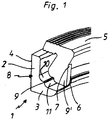
- FIG. 1 shows a sliding and / or mating ring 1 of a drive seal not shown here.
- the sliding ring and / or counter ring 1, referred to below as a sliding ring, includes a radial leg 2 and an axial leg 3.
- a sliding surface 4 is provided on the radial leg side.
- the axial leg 3 receives a trained as a trapezoidal sealing body elastomer body 5.
- the free end of the axial leg 3 is provided, seen in the circumferential direction, anti-rotation forming, recesses 6, in which approximately correspondingly formed lugs 7 of the sealing body 5 engage.
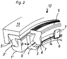
- FIG. 2 shows a mechanical seal 12 in perspective and in cutaway form.
- the mechanical seal 12 includes a sliding ring 1 and a, attributable to the prior art counter-ring 1 '.
- Elastic sealing bodies 5, 5 ' are used, which are supported between the respective axial leg 3, 3' and corresponding housing parts 13.
- the opposing side region of the mechanical seal 12 includes a counter ring 1 with not shown anti-rotation.
- the slip ring 1 discloses the already in FIG. 1 indicated profiling 9, wherein the recesses 6 in the axial leg 3 are clearly visible. In these recesses 6, the reinforced lugs 7 of the sealing body 5 engage.
- the anti-rotation lock between the sliding ring 1 and the sealing body 5 is improved over the prior art by bringing the position of the anti-twist close to the heavily loaded contact area 8 between the sealing body 5 and the profiling 9 is thus in the range of low deformations of the elastomeric material.
- elastomeric material 14 which is supported at least on the anti-rotation portion facing the axial leg 3.
Description
- Die Erfindung betrifft eine Gleitringdichtung, insbesondere eine Laufwerkdichtung, gemäß gattungsbildendem Teil des ersten Patentanspruchs.
Laufwerkdichtungen mit Gummitrapezringen besitzen aufgrund der geringen erzeugten Kräfte durch das Elastomerteil nur geringe Haltemomente zwischen dem Elastomerteil und dem Gleit- und/oder Gegenring. Bereits durch mittelmäßige Schmutzangriffe von außen, welche die Verdrehkräfte erhöhen, kann ein Verdrehen zwischen dem Elastomerteil und dem Gleit- und/oder Gegenring erzeugt werden. - Durch erhöhte Belastungen, z.B. durch Schmutzeintrag und Korrosionsangriffe, kann ein erhöhtes Verdrehmoment zwischen dem Gleit- und/oder Gegenring und dem Elastomerteil resultieren. Eine Relativbewegung zwischen den Gleit- und/oder Gegenringen und dem Elastomerteil bewirken Elastomerverschleiß und daraus folgend Dichtungsversagen.
- Eine gattungsgemäße Gleitringdichtung mit radialer Verdrehsicherung ist der
DE 101 04 788 A1 zu entnehmen. Die bisherigen Verdrehsicherungen zeigen nur mangelhaften Schutz, da die Verdrehsicherung relativ weit vom hochbelasteten und somit wenig verformten Bereich des Dichtkörpers entfernt ist. Die grundsätzliche Verformung des Dichtkörpers im Einbauzustand kann zu einem Abheben des hinteren Bereichs des Elastomerteils und somit auch zum Ausheben der Verdrehsicherung aus der Aussparung des Gleit- und/oder Gegenrings führen. Sofern der Gleit- und/oder Gegenring anfängt sich zu verdrehen, führt die geringe Steifigkeit des Gleit- und/oder Gegenrings zur Deformation der Verdrehsicherung und somit zum vollständigen Verlust des Formschlusses und damit zum Wirkungsverlust der Gleitringdichtung. - Der Gleit- und/oder Gegenring besitzt einen hoch belasteten Bereich, der durch den Übergangsbereich zwischen dem Axial- in den Radialschenkel des Gleit- und/oder Gegenringes gebildet wird. Je weiter die vom hochbelasteten Bereich entfernte Verdrehsicherung zwischen dem Gleit- und/oder Gegenring und dem Elastomerteil angeordnet ist, kann eine elastische Verformung der Verdrehsicherung bewirken, bei welcher der Formschluss und somit die Verdrehsicherung nicht mehr sichergestellt ist. Die Erfindung liegt die Aufgabe zugrunde, ausgehend vom Stand der Technik gemäß
DE 101 04 788 A1 , eine Gleitringdichtung, insbesondere eine Laufwerkdichtung bereitzustellen, die mit einer optimierten Verdrehsicherung versehen ist. - Diese Aufgabe wird dadurch gelöst, dass der außerhalb der Gleitfläche vorgesehene Übergangsbereich vom Axial- in den Radialschenkel des Gleit- und/oder Gegenrings mit einer Profilierung versehen ist, in welche ein etwa korrespondierend ausgebildeter Abschnitt des Dichtkörpers eingreift, wobei die Profilierung durch mindestens einen umlaufend ausgebildeten Ansatz gebildet wird. Vorteilhafte Weiterbildungen des Erfindungsgegenstandes sind den Unteransprüchen zu entnehmen.
- Durch den mindestens einen absatzartig ausgebildeten Übergangsbereich vom Axial- in den Radialschenkel des Gleit- und/oder Gegenrings wird die aus dem Stand der Technik bekannte Verdrehsicherung näher an den hochbelasteten Bereich des jeweiligen Gleit- und/oder Gegenrings gebracht und macht somit ein Ausweichen der Verdrehsicherung durch elastische Verformung unmöglich. Infolge der massiven Geometrie der Verdrehsicherung werden auch hohe Kräfte durch den Formschluss aufgenommen und führen zu keinem Abscheren des Elastomermaterials.
- Von Vorteil ist, den Übergangsbereich vom Radial- in den Axialschenkel gerundet auszubilden, so dass zwischen den jeweiligen Übergangsbereichen eine, bedarfsweise gerundet ausgebildete Kante gebildet wird.
- Einem weiteren Gedanken der Erfindung gemäß läuft der einzelne bzw. der letzte Absatz in ebenfalls gerundeter Form in den Axialschenkel des Gleit- und/oder Gegenrings ein.
- Ähnlich wie beim Stand der Technik können auch hier, in Umfangsrichtung des Gleit- und/oder Gegenrings gesehen, am äußeren Ende des jeweiligen axialen Schenkels mehrere Ausnehmungen eingebracht werden, in welche, Verdrehsicherungen bildende, Ansätze des Dichtkörpers eingreifen.
- Der Erfindungsgegenstand ist anhand eines Ausführungsbeispiels in der Zeichnung dargestellt und wird wie folgt beschrieben. Es zeigen:
- Figur 1
- Prinzipskizze eines erfindungsgemäßen Gleit- und/oder Gegenrings einer nicht weiter dargestellten Laufwerkdichtung im Querschnitt;
- Figur 2
- Laufwerkdichtung, einerseits gemäß Stand der Technik und andererseits gemäß Erfindung, in perspektivischer Darstellung sowie im Teilschnitt.
-
Figur 1 zeigt einen Gleit- und/oder Gegenring 1 einer hier nicht weiter dargestellten Laufwerkdichtung. Der im Folgenden als Gleitring bezeichnete Gleit- und/oder Gegenring 1 beinhaltet einen Radialschenkel 2 sowie einen Axialschenkel 3. Radialschenkelseitig ist eine Gleitfläche 4 vorgesehen. Der Axialschenkel 3 nimmt einen als trapezförmigen Dichtkörper ausgebildeten Elastomerkörper 5 auf. - Das freie Ende des Axialschenkels 3 ist mit, in Umfangsrichtung gesehen, Verdrehsicherungen bildenden, Ausnehmungen 6 versehen, in welche etwa korrespondierend ausgebildete Ansätze 7 des Dichtkörpers 5 eingreifen.
- Abweichend zum Stand der Technik wird die jeweilige Verdrehsicherung durch entsprechende Formgestaltung der Ansätze 7 in die Nähe des hochbelasteten Kontaktbereichs 8, d.h. in Richtung des Übergangsbereichs vom Radialschenkel 2 in den Axialschenkel 3, verlegt. Zu dem Zweck wird der Übergangsbereich zwischen dem Radialschenkel 2 und dem Axialschenkel 3 mit einer Profilierung 9 versehen, die in diesem Beispiel als einstufiger Absatz ausgebildet ist. Der Übergang vom Radialschenkel 2 in den Absatz 9 ist mit einer Rundung 10 vorgebbarer Kurvengeometrie ausgeführt. Gleiches gilt für den Übergang des Absatzes 9 in den Axialschenkel 3, wobei auch hier eine Rundung 11 vorgebbarer geometrischer Kontur vorgesehen ist. Der Dichtkörper 5 verfügt über einen der Profilierung 9 entsprechenden Abschnitt 9', mit welchem er sich auf der Profilierung 9 abstützt.
-
Figur 2 zeigt eine Gleitringdichtung 12 in perspektivischer Darstellung sowie in aufgeschnittener Form. Die Gleitringdichtung 12 beinhaltet einen Gleitring 1 sowie einen, dem Stand der Technik zuzuordnenden Gegenring 1'. Zum Einsatz gelangen elastomere Dichtkörper 5,5', die sich zwischen dem jeweiligen Axialschenkel 3,3' und korrespondierenden Gehäuseteilen 13 abstützen. Der gegenringseitige Bereich der Gleitringdichtung 12 beinhaltet einen Gegenring 1 mit nicht näher dargestellter Verdrehsicherung. Der Gleitring 1 gemäß Erfindungsgegenstand offenbart die bereits inFigur 1 angedeutete Profilierung 9, wobei die Ausnehmungen 6 im Axialschenkel 3 gut erkennbar sind. In diese Ausnehmungen 6 greifen die verstärkten Ansätze 7 des Dichtkörpers 5 ein. Wie dem Querschnitt des rechten Bildes der Gleitringdichtung 12 zu entnehmen ist, wird die Verdrehsicherung zwischen dem Gleitring 1 und dem Dichtkörper 5 gegenüber dem Stand der Technik dadurch verbessert, dass die Lage der Verdrehsicherung nahe an den hochbelasteten Kontaktbereich 8 zwischen Dichtkörper 5 und Profilierung 9 herangeführt wird und somit im Bereich geringer Verformungen des Elastomermaterials liegt. Ein Abheben oder eine Verformung der Verdrehsicherung, die zu einem Formschlussverlust führen könnte, ist praktisch ausgeschlossen. Zwischen einzelnen, Verdrehsicherungen bildenden, Ansätzen 7 des Dichtkörpers 5 erstreckt sich Elastomermaterial 14, das zumindest auf dem der Verdrehsicherung zugewandten Abschnitt des Axialschenkels 3 abgestützt ist. - Mit dem Erfindungsgegenstand wird eine sehr massive Ausführung der Verdrehsicherung herbeigeführt, um auch hohe Verdrehkräfte aufnehmen zu können. In Abhängigkeit der aufzunehmenden Verdrehkräfte wird die Anzahl der Ansätze 7 am Dichtkörper 5, respektive der Ausnehmungen 6 am Axialschenkel 3 des Gleitrings 1, vorgesehen.
Claims (5)
- Gleitringdichtung, zumindest bestehend aus einem winkelförmigen Gleit- und/oder Gegenring (1), dessen radialer Schenkel (2) mit einer Gleitfläche (4) versehen ist und dessen axialer Schenkel (3) eine Aufnahme für einen trapezförmig ausgebildeten Dichtkörper (5) bildet, wobei das dem Radialschenkel (2) zugewandte Ende des axialen Schenkels (3) Ausnehmungen (6) aufweist, in welche am Dichtkörper (5) angeformte, Verdrehsicherungen bildende, Ansätze (7) eingreifen, dadurch gekennzeichnet, dass der außerhalb der Gleitfläche (4) vorgesehene Übergangsbereich (8) vom Axial- (3) in den Radialschenkel (2) des Gleit- und/oder Gegenrings (1) mit einer Profilierung (9) versehen ist, in welche ein, etwa korrespondierend ausgebildeter Abschnitt (9') des Dichtkörpers (5) eingreift, wobei die Profilierung (9) durch mindestens einen umlaufend ausgebildeten Absatz gebildet ist.
- Gleitringdichtung nach Anspruch 1, dadurch gekennzeichnet, dass der Übergangsbereich (8) vom Radial- (2) in den Axialschenkel (3) gerundet (10) ausgebildet ist und axialschenkelseitig in den Absatz (9) übergeht.
- Gleitringdichtung nach Anspruch 1 oder 2, dadurch gekennzeichnet, dass der Absatz (9) in gerundeter Form (10) in den Axialschenkel (3) einläuft.
- Gleitringdichtung nach einem der Ansprüche 1 bis 3, gekennzeichnet durch eine Mehrzahl von, in Umfangsrichtung gesehen, Verdrehsicherungen bildenden, Ansätzen (7) am Dichtkörper (5), die in korrespondierende Ausnehmungen (6) des Axialschenkels (3) eingreifen.
- Gleitringdichtung nach einem der Ansprüche 1 bis 4, dadurch gekennzeichnet, dass, in Umfangsrichtung gesehen, zwischen einzelnen Ansätzen (7) Elastomermaterial vorgesehen ist, das zumindest auf dem in Richtung der Verdrehsicherung verlaufenden Abschnitt des Axialschenkels (3) abgestützt ist.
Priority Applications (2)
| Application Number | Priority Date | Filing Date | Title |
|---|---|---|---|
| PL12714933T PL2683969T3 (pl) | 2011-03-08 | 2012-02-29 | Uszczelnienie pierścieniem ślizgowym |
| SI201231127T SI2683969T1 (en) | 2011-03-08 | 2012-02-29 | Gasket ring gasket |
Applications Claiming Priority (2)
| Application Number | Priority Date | Filing Date | Title |
|---|---|---|---|
| DE102011013366.6A DE102011013366B4 (de) | 2011-03-08 | 2011-03-08 | Gleitringdichtung |
| PCT/DE2012/000211 WO2012119579A1 (de) | 2011-03-08 | 2012-02-29 | Gleitringdichtung |
Publications (2)
| Publication Number | Publication Date |
|---|---|
| EP2683969A1 EP2683969A1 (de) | 2014-01-15 |
| EP2683969B1 true EP2683969B1 (de) | 2017-09-20 |
Family
ID=45976007
Family Applications (1)
| Application Number | Title | Priority Date | Filing Date |
|---|---|---|---|
| EP12714933.4A Active EP2683969B1 (de) | 2011-03-08 | 2012-02-29 | Gleitringdichtung |
Country Status (9)
| Country | Link |
|---|---|
| US (1) | US9404583B2 (de) |
| EP (1) | EP2683969B1 (de) |
| JP (1) | JP6053697B2 (de) |
| KR (1) | KR101882432B1 (de) |
| CN (1) | CN103380321B (de) |
| DE (1) | DE102011013366B4 (de) |
| PL (1) | PL2683969T3 (de) |
| SI (1) | SI2683969T1 (de) |
| WO (1) | WO2012119579A1 (de) |
Family Cites Families (29)
| Publication number | Priority date | Publication date | Assignee | Title |
|---|---|---|---|---|
| US1180A (en) | 1839-06-21 | Springs for railroad-cars | ||
| AT72696B (de) | 1914-06-05 | 1916-11-10 | Hubert Endemann | Schloß für die Schaltbewegung des Papierwagens bei Schreibmaschinen und dgl. |
| US3524654A (en) * | 1968-02-26 | 1970-08-18 | Caterpillar Tractor Co | Face seal assembly |
| FR1599308A (de) * | 1968-06-08 | 1970-07-15 | ||
| US3761114A (en) * | 1971-08-30 | 1973-09-25 | Victaulic Co Ltd | Pipe to flange couplings |
| US4183542A (en) * | 1977-10-21 | 1980-01-15 | Fonderia R. Bertoldo & C. S.a.s. | Rotating face sealing gasket, particularly for use on tracked vehicles |
| US4421327A (en) * | 1981-12-17 | 1983-12-20 | Morley James P | Heavy duty end face seal with asymmetrical cross-section |
| JPS58129367A (ja) | 1982-01-29 | 1983-08-02 | Omron Tateisi Electronics Co | 空間フイルタの測定デ−タ処理方法 |
| JPS58129367U (ja) * | 1982-02-26 | 1983-09-01 | イ−グル工業株式会社 | メカニカルシ−ル |
| US4753303A (en) * | 1983-10-17 | 1988-06-28 | Hughes Tool Company--USA | Earth boring bit with two piece bearing and rigid face seal assembly |
| DE3776744D1 (de) * | 1986-07-18 | 1992-03-26 | Loredana Nibio | Ring fuer schleifringdichtung. |
| JPH07107026B2 (ja) | 1987-06-25 | 1995-11-15 | 日本ケミファ株式会社 | 2−アミノベンジルアルコ−ル誘導体 |
| JPH0247314Y2 (de) | 1987-06-26 | 1990-12-12 | ||
| DE3740694A1 (de) * | 1987-12-01 | 1989-06-22 | Goetze Ag | Gleitringdichtung |
| JPH0641392B2 (ja) | 1990-07-14 | 1994-06-01 | 東海パルプ株式会社 | 軽量コンクリート製品とその製造方法および軽量生コンクリートとその製造方法 |
| JPH0474775U (de) * | 1990-11-01 | 1992-06-30 | ||
| USH1180H (en) * | 1991-12-23 | 1993-05-04 | Caterpillar Inc. | Face seal with increased torque transfer capacity |
| US5791421A (en) * | 1996-08-06 | 1998-08-11 | Baker Hughes Incorporated | Optimal material pair for metal face seal in earth-boring bits |
| WO1999031411A1 (en) * | 1997-12-12 | 1999-06-24 | Caterpillar Inc. | Face seal assembly with interfitting load ring |
| DE29823662U1 (de) * | 1998-05-29 | 1999-11-18 | Federal Mogul Burscheid Gmbh | Gleitringdichtung |
| DE19944860A1 (de) | 1999-09-18 | 2001-03-22 | Geophysikalisches Messen Und G | Verfahren zur effektiven Einbringung von kohäsiven Teilsäulen bei der Schachtverfüllung |
| DE19955860B4 (de) * | 1999-11-20 | 2004-04-08 | Federal-Mogul Burscheid Gmbh | Gleitringdichtung |
| DE10104788C2 (de) * | 2001-02-02 | 2003-06-26 | Federal Mogul Friedberg Gmbh | Gleitringdichtung mit radialer Verdrehsicherung |
| DE10148929C2 (de) * | 2001-10-04 | 2003-11-27 | Federal Mogul Friedberg Gmbh | Gleitringdichtung mit axialem Spielausgleich |
| US20040026870A1 (en) * | 2002-08-06 | 2004-02-12 | Maguire Roy L. | Face seal assembly with integral support |
| DE102008036489B3 (de) * | 2008-08-06 | 2010-05-06 | Federal-Mogul Burscheid Gmbh | Laufwerkdichtung |
| US20110048810A1 (en) * | 2009-08-26 | 2011-03-03 | Baker Hughes Incorporated | Synergic surface modification for bearing seal |
| CA2792914C (en) * | 2010-03-15 | 2016-03-01 | John Crane Inc. | Split seal assembly and method |
| DE102010024289A1 (de) * | 2010-04-23 | 2011-10-27 | Carl Freudenberg Kg | Gleitringdichtung |
-
2011
- 2011-03-08 DE DE102011013366.6A patent/DE102011013366B4/de not_active Expired - Fee Related
-
2012
- 2012-02-29 SI SI201231127T patent/SI2683969T1/en unknown
- 2012-02-29 KR KR1020137020682A patent/KR101882432B1/ko active IP Right Grant
- 2012-02-29 CN CN201280009439.XA patent/CN103380321B/zh active Active
- 2012-02-29 WO PCT/DE2012/000211 patent/WO2012119579A1/de active Application Filing
- 2012-02-29 EP EP12714933.4A patent/EP2683969B1/de active Active
- 2012-02-29 PL PL12714933T patent/PL2683969T3/pl unknown
- 2012-02-29 JP JP2013556965A patent/JP6053697B2/ja active Active
- 2012-02-29 US US14/003,982 patent/US9404583B2/en active Active
Non-Patent Citations (1)
| Title |
|---|
| None * |
Also Published As
| Publication number | Publication date |
|---|---|
| JP2014507615A (ja) | 2014-03-27 |
| KR20140036149A (ko) | 2014-03-25 |
| SI2683969T1 (en) | 2018-01-31 |
| US20130341871A1 (en) | 2013-12-26 |
| CN103380321B (zh) | 2016-02-10 |
| EP2683969A1 (de) | 2014-01-15 |
| JP6053697B2 (ja) | 2016-12-27 |
| US9404583B2 (en) | 2016-08-02 |
| CN103380321A (zh) | 2013-10-30 |
| WO2012119579A1 (de) | 2012-09-13 |
| DE102011013366B4 (de) | 2014-10-02 |
| PL2683969T3 (pl) | 2018-02-28 |
| DE102011013366A1 (de) | 2012-09-13 |
| KR101882432B1 (ko) | 2018-07-26 |
Similar Documents
| Publication | Publication Date | Title |
|---|---|---|
| DE102011102463A1 (de) | Kettenrad | |
| EP3132163B1 (de) | Gleitringdichtungsanordnung mit balgelement | |
| DE69918910T3 (de) | Ringförmige Dichtung, insbesondere für eine Antriebswelle eines Kraftfahrzeuges | |
| DE102014007798A1 (de) | Buchsenanordnung zur Zentrierung zweier zu verbindender Wellenabschnitte | |
| WO2005098248A1 (de) | Dichtungsbalg | |
| DE102011121281A1 (de) | Maul- oder klauenförmige Spaltdichtung | |
| DE102011008088A1 (de) | Sealing gasket | |
| DE202011109164U1 (de) | Maul- oder klauenförmige Spaltdichtung | |
| DE2510074A1 (de) | Endverbindungsstueck fuer schlaeuche | |
| DE102011011475A1 (de) | Gleitringdichtung | |
| EP2683969B1 (de) | Gleitringdichtung | |
| EP2527694B1 (de) | Maul- oder klauenförmige Spaltdichtung | |
| EP2016313B1 (de) | Kolbenring für den kolben eines verbrennungsmotors | |
| DE102017209685A1 (de) | Spindelantrieb für einen Aktuator, insbesondere einer Hinterachslenkung | |
| DE102010018552B4 (de) | Dichtungsanordnung und Gelenk einer Kette mit der Dichtungsanordnung | |
| EP3201498B1 (de) | Hakenschloss für eine rechteckdichtung sowie eine ein derartiges hakenschloss aufweisende rechteckdichtung | |
| EP2993089B1 (de) | Sperrkranzverriegelung | |
| DE102014220384B4 (de) | Kraftstoffhochdruckpumpe und Antriebswelle | |
| DE102008041829B4 (de) | Gelenkverbindungsanordnung in einer Scheibenwischvorrichtung | |
| DE10225948A1 (de) | Elastische Kupplung | |
| DE202010013917U1 (de) | Dichtungsprofil oder Element zum Abdichten | |
| DE102009035739A1 (de) | Dichtungseinrichtung für ein Drehlager | |
| EP2397716A2 (de) | Elastische kupplung | |
| DE10047493C2 (de) | Gleitringdichtung mit Leckagesperre | |
| DE19505853C2 (de) | Gleit- und/oder Gegenring |
Legal Events
| Date | Code | Title | Description |
|---|---|---|---|
| PUAI | Public reference made under article 153(3) epc to a published international application that has entered the european phase |
Free format text: ORIGINAL CODE: 0009012 |
|
| 17P | Request for examination filed |
Effective date: 20130705 |
|
| AK | Designated contracting states |
Kind code of ref document: A1 Designated state(s): AL AT BE BG CH CY CZ DE DK EE ES FI FR GB GR HR HU IE IS IT LI LT LU LV MC MK MT NL NO PL PT RO RS SE SI SK SM TR |
|
| DAX | Request for extension of the european patent (deleted) | ||
| 17Q | First examination report despatched |
Effective date: 20160609 |
|
| GRAP | Despatch of communication of intention to grant a patent |
Free format text: ORIGINAL CODE: EPIDOSNIGR1 |
|
| INTG | Intention to grant announced |
Effective date: 20170620 |
|
| GRAS | Grant fee paid |
Free format text: ORIGINAL CODE: EPIDOSNIGR3 |
|
| GRAA | (expected) grant |
Free format text: ORIGINAL CODE: 0009210 |
|
| AK | Designated contracting states |
Kind code of ref document: B1 Designated state(s): AL AT BE BG CH CY CZ DE DK EE ES FI FR GB GR HR HU IE IS IT LI LT LU LV MC MK MT NL NO PL PT RO RS SE SI SK SM TR |
|
| REG | Reference to a national code |
Ref country code: GB Ref legal event code: FG4D Free format text: NOT ENGLISH |
|
| REG | Reference to a national code |
Ref country code: CH Ref legal event code: EP |
|
| REG | Reference to a national code |
Ref country code: AT Ref legal event code: REF Ref document number: 930422 Country of ref document: AT Kind code of ref document: T Effective date: 20171015 |
|
| REG | Reference to a national code |
Ref country code: IE Ref legal event code: FG4D Free format text: LANGUAGE OF EP DOCUMENT: GERMAN |
|
| REG | Reference to a national code |
Ref country code: DE Ref legal event code: R096 Ref document number: 502012011308 Country of ref document: DE |
|
| REG | Reference to a national code |
Ref country code: FR Ref legal event code: PLFP Year of fee payment: 7 |
|
| REG | Reference to a national code |
Ref country code: NL Ref legal event code: MP Effective date: 20170920 |
|
| PG25 | Lapsed in a contracting state [announced via postgrant information from national office to epo] |
Ref country code: FI Free format text: LAPSE BECAUSE OF FAILURE TO SUBMIT A TRANSLATION OF THE DESCRIPTION OR TO PAY THE FEE WITHIN THE PRESCRIBED TIME-LIMIT Effective date: 20170920 Ref country code: SE Free format text: LAPSE BECAUSE OF FAILURE TO SUBMIT A TRANSLATION OF THE DESCRIPTION OR TO PAY THE FEE WITHIN THE PRESCRIBED TIME-LIMIT Effective date: 20170920 Ref country code: HR Free format text: LAPSE BECAUSE OF FAILURE TO SUBMIT A TRANSLATION OF THE DESCRIPTION OR TO PAY THE FEE WITHIN THE PRESCRIBED TIME-LIMIT Effective date: 20170920 Ref country code: LT Free format text: LAPSE BECAUSE OF FAILURE TO SUBMIT A TRANSLATION OF THE DESCRIPTION OR TO PAY THE FEE WITHIN THE PRESCRIBED TIME-LIMIT Effective date: 20170920 Ref country code: NO Free format text: LAPSE BECAUSE OF FAILURE TO SUBMIT A TRANSLATION OF THE DESCRIPTION OR TO PAY THE FEE WITHIN THE PRESCRIBED TIME-LIMIT Effective date: 20171220 |
|
| REG | Reference to a national code |
Ref country code: LT Ref legal event code: MG4D |
|
| PG25 | Lapsed in a contracting state [announced via postgrant information from national office to epo] |
Ref country code: RS Free format text: LAPSE BECAUSE OF FAILURE TO SUBMIT A TRANSLATION OF THE DESCRIPTION OR TO PAY THE FEE WITHIN THE PRESCRIBED TIME-LIMIT Effective date: 20170920 Ref country code: LV Free format text: LAPSE BECAUSE OF FAILURE TO SUBMIT A TRANSLATION OF THE DESCRIPTION OR TO PAY THE FEE WITHIN THE PRESCRIBED TIME-LIMIT Effective date: 20170920 Ref country code: GR Free format text: LAPSE BECAUSE OF FAILURE TO SUBMIT A TRANSLATION OF THE DESCRIPTION OR TO PAY THE FEE WITHIN THE PRESCRIBED TIME-LIMIT Effective date: 20171221 Ref country code: BG Free format text: LAPSE BECAUSE OF FAILURE TO SUBMIT A TRANSLATION OF THE DESCRIPTION OR TO PAY THE FEE WITHIN THE PRESCRIBED TIME-LIMIT Effective date: 20171220 |
|
| PG25 | Lapsed in a contracting state [announced via postgrant information from national office to epo] |
Ref country code: NL Free format text: LAPSE BECAUSE OF FAILURE TO SUBMIT A TRANSLATION OF THE DESCRIPTION OR TO PAY THE FEE WITHIN THE PRESCRIBED TIME-LIMIT Effective date: 20170920 |
|
| PG25 | Lapsed in a contracting state [announced via postgrant information from national office to epo] |
Ref country code: ES Free format text: LAPSE BECAUSE OF FAILURE TO SUBMIT A TRANSLATION OF THE DESCRIPTION OR TO PAY THE FEE WITHIN THE PRESCRIBED TIME-LIMIT Effective date: 20170920 Ref country code: CZ Free format text: LAPSE BECAUSE OF FAILURE TO SUBMIT A TRANSLATION OF THE DESCRIPTION OR TO PAY THE FEE WITHIN THE PRESCRIBED TIME-LIMIT Effective date: 20170920 Ref country code: RO Free format text: LAPSE BECAUSE OF FAILURE TO SUBMIT A TRANSLATION OF THE DESCRIPTION OR TO PAY THE FEE WITHIN THE PRESCRIBED TIME-LIMIT Effective date: 20170920 |
|
| PG25 | Lapsed in a contracting state [announced via postgrant information from national office to epo] |
Ref country code: SM Free format text: LAPSE BECAUSE OF FAILURE TO SUBMIT A TRANSLATION OF THE DESCRIPTION OR TO PAY THE FEE WITHIN THE PRESCRIBED TIME-LIMIT Effective date: 20170920 Ref country code: IS Free format text: LAPSE BECAUSE OF FAILURE TO SUBMIT A TRANSLATION OF THE DESCRIPTION OR TO PAY THE FEE WITHIN THE PRESCRIBED TIME-LIMIT Effective date: 20180120 Ref country code: EE Free format text: LAPSE BECAUSE OF FAILURE TO SUBMIT A TRANSLATION OF THE DESCRIPTION OR TO PAY THE FEE WITHIN THE PRESCRIBED TIME-LIMIT Effective date: 20170920 |
|
| REG | Reference to a national code |
Ref country code: DE Ref legal event code: R097 Ref document number: 502012011308 Country of ref document: DE |
|
| PLBE | No opposition filed within time limit |
Free format text: ORIGINAL CODE: 0009261 |
|
| STAA | Information on the status of an ep patent application or granted ep patent |
Free format text: STATUS: NO OPPOSITION FILED WITHIN TIME LIMIT |
|
| PG25 | Lapsed in a contracting state [announced via postgrant information from national office to epo] |
Ref country code: DK Free format text: LAPSE BECAUSE OF FAILURE TO SUBMIT A TRANSLATION OF THE DESCRIPTION OR TO PAY THE FEE WITHIN THE PRESCRIBED TIME-LIMIT Effective date: 20170920 |
|
| 26N | No opposition filed |
Effective date: 20180621 |
|
| REG | Reference to a national code |
Ref country code: CH Ref legal event code: PL |
|
| PG25 | Lapsed in a contracting state [announced via postgrant information from national office to epo] |
Ref country code: MC Free format text: LAPSE BECAUSE OF FAILURE TO SUBMIT A TRANSLATION OF THE DESCRIPTION OR TO PAY THE FEE WITHIN THE PRESCRIBED TIME-LIMIT Effective date: 20170920 Ref country code: MT Free format text: LAPSE BECAUSE OF FAILURE TO SUBMIT A TRANSLATION OF THE DESCRIPTION OR TO PAY THE FEE WITHIN THE PRESCRIBED TIME-LIMIT Effective date: 20170920 |
|
| REG | Reference to a national code |
Ref country code: IE Ref legal event code: MM4A |
|
| REG | Reference to a national code |
Ref country code: BE Ref legal event code: MM Effective date: 20180228 |
|
| PG25 | Lapsed in a contracting state [announced via postgrant information from national office to epo] |
Ref country code: LI Free format text: LAPSE BECAUSE OF NON-PAYMENT OF DUE FEES Effective date: 20180228 Ref country code: LU Free format text: LAPSE BECAUSE OF NON-PAYMENT OF DUE FEES Effective date: 20180228 Ref country code: CH Free format text: LAPSE BECAUSE OF NON-PAYMENT OF DUE FEES Effective date: 20180228 |
|
| PG25 | Lapsed in a contracting state [announced via postgrant information from national office to epo] |
Ref country code: IE Free format text: LAPSE BECAUSE OF NON-PAYMENT OF DUE FEES Effective date: 20180228 |
|
| PG25 | Lapsed in a contracting state [announced via postgrant information from national office to epo] |
Ref country code: BE Free format text: LAPSE BECAUSE OF NON-PAYMENT OF DUE FEES Effective date: 20180228 |
|
| REG | Reference to a national code |
Ref country code: AT Ref legal event code: MM01 Ref document number: 930422 Country of ref document: AT Kind code of ref document: T Effective date: 20180228 |
|
| PG25 | Lapsed in a contracting state [announced via postgrant information from national office to epo] |
Ref country code: AT Free format text: LAPSE BECAUSE OF NON-PAYMENT OF DUE FEES Effective date: 20180228 |
|
| PG25 | Lapsed in a contracting state [announced via postgrant information from national office to epo] |
Ref country code: PT Free format text: LAPSE BECAUSE OF FAILURE TO SUBMIT A TRANSLATION OF THE DESCRIPTION OR TO PAY THE FEE WITHIN THE PRESCRIBED TIME-LIMIT Effective date: 20170920 Ref country code: HU Free format text: LAPSE BECAUSE OF FAILURE TO SUBMIT A TRANSLATION OF THE DESCRIPTION OR TO PAY THE FEE WITHIN THE PRESCRIBED TIME-LIMIT; INVALID AB INITIO Effective date: 20120229 |
|
| PG25 | Lapsed in a contracting state [announced via postgrant information from national office to epo] |
Ref country code: CY Free format text: LAPSE BECAUSE OF FAILURE TO SUBMIT A TRANSLATION OF THE DESCRIPTION OR TO PAY THE FEE WITHIN THE PRESCRIBED TIME-LIMIT Effective date: 20170920 Ref country code: MK Free format text: LAPSE BECAUSE OF NON-PAYMENT OF DUE FEES Effective date: 20170920 |
|
| PG25 | Lapsed in a contracting state [announced via postgrant information from national office to epo] |
Ref country code: AL Free format text: LAPSE BECAUSE OF FAILURE TO SUBMIT A TRANSLATION OF THE DESCRIPTION OR TO PAY THE FEE WITHIN THE PRESCRIBED TIME-LIMIT Effective date: 20170920 |
|
| PGFP | Annual fee paid to national office [announced via postgrant information from national office to epo] |
Ref country code: FR Payment date: 20230119 Year of fee payment: 12 |
|
| PGFP | Annual fee paid to national office [announced via postgrant information from national office to epo] |
Ref country code: TR Payment date: 20230125 Year of fee payment: 12 Ref country code: SK Payment date: 20230123 Year of fee payment: 12 Ref country code: SI Payment date: 20230131 Year of fee payment: 12 Ref country code: PL Payment date: 20230123 Year of fee payment: 12 Ref country code: IT Payment date: 20230120 Year of fee payment: 12 Ref country code: GB Payment date: 20230121 Year of fee payment: 12 Ref country code: DE Payment date: 20230119 Year of fee payment: 12 |
|
| P01 | Opt-out of the competence of the unified patent court (upc) registered |
Effective date: 20230528 |