EP2683634B1 - Dipping-treatment installation for vehicle bodies, and a method for operating same - Google Patents
Dipping-treatment installation for vehicle bodies, and a method for operating same Download PDFInfo
- Publication number
- EP2683634B1 EP2683634B1 EP12706486.3A EP12706486A EP2683634B1 EP 2683634 B1 EP2683634 B1 EP 2683634B1 EP 12706486 A EP12706486 A EP 12706486A EP 2683634 B1 EP2683634 B1 EP 2683634B1
- Authority
- EP
- European Patent Office
- Prior art keywords
- robot
- dipping
- axis
- basin
- treatment
- Prior art date
- Legal status (The legal status is an assumption and is not a legal conclusion. Google has not performed a legal analysis and makes no representation as to the accuracy of the status listed.)
- Not-in-force
Links
Images


Classifications
-
- B—PERFORMING OPERATIONS; TRANSPORTING
- B65—CONVEYING; PACKING; STORING; HANDLING THIN OR FILAMENTARY MATERIAL
- B65G—TRANSPORT OR STORAGE DEVICES, e.g. CONVEYORS FOR LOADING OR TIPPING, SHOP CONVEYOR SYSTEMS OR PNEUMATIC TUBE CONVEYORS
- B65G49/00—Conveying systems characterised by their application for specified purposes not otherwise provided for
- B65G49/02—Conveying systems characterised by their application for specified purposes not otherwise provided for for conveying workpieces through baths of liquid
- B65G49/04—Conveying systems characterised by their application for specified purposes not otherwise provided for for conveying workpieces through baths of liquid the workpieces being immersed and withdrawn by movement in a vertical direction
- B65G49/0409—Conveying systems characterised by their application for specified purposes not otherwise provided for for conveying workpieces through baths of liquid the workpieces being immersed and withdrawn by movement in a vertical direction specially adapted for workpieces of definite length
- B65G49/0436—Conveying systems characterised by their application for specified purposes not otherwise provided for for conveying workpieces through baths of liquid the workpieces being immersed and withdrawn by movement in a vertical direction specially adapted for workpieces of definite length arrangements for conveyance from bath to bath
- B65G49/044—Conveying systems characterised by their application for specified purposes not otherwise provided for for conveying workpieces through baths of liquid the workpieces being immersed and withdrawn by movement in a vertical direction specially adapted for workpieces of definite length arrangements for conveyance from bath to bath along a continuous circuit
- B65G49/045—Conveying systems characterised by their application for specified purposes not otherwise provided for for conveying workpieces through baths of liquid the workpieces being immersed and withdrawn by movement in a vertical direction specially adapted for workpieces of definite length arrangements for conveyance from bath to bath along a continuous circuit the circuit being fixed
- B65G49/0454—Conveying systems characterised by their application for specified purposes not otherwise provided for for conveying workpieces through baths of liquid the workpieces being immersed and withdrawn by movement in a vertical direction specially adapted for workpieces of definite length arrangements for conveyance from bath to bath along a continuous circuit the circuit being fixed by means of containers -or workpieces- carriers
- B65G49/0459—Conveying systems characterised by their application for specified purposes not otherwise provided for for conveying workpieces through baths of liquid the workpieces being immersed and withdrawn by movement in a vertical direction specially adapted for workpieces of definite length arrangements for conveyance from bath to bath along a continuous circuit the circuit being fixed by means of containers -or workpieces- carriers movement in a vertical direction is caused by self-contained means
-
- B—PERFORMING OPERATIONS; TRANSPORTING
- B05—SPRAYING OR ATOMISING IN GENERAL; APPLYING FLUENT MATERIALS TO SURFACES, IN GENERAL
- B05B—SPRAYING APPARATUS; ATOMISING APPARATUS; NOZZLES
- B05B13/00—Machines or plants for applying liquids or other fluent materials to surfaces of objects or other work by spraying, not covered by groups B05B1/00 - B05B11/00
- B05B13/02—Means for supporting work; Arrangement or mounting of spray heads; Adaptation or arrangement of means for feeding work
- B05B13/0221—Means for supporting work; Arrangement or mounting of spray heads; Adaptation or arrangement of means for feeding work characterised by the means for moving or conveying the objects or other work, e.g. conveyor belts
-
- B—PERFORMING OPERATIONS; TRANSPORTING
- B05—SPRAYING OR ATOMISING IN GENERAL; APPLYING FLUENT MATERIALS TO SURFACES, IN GENERAL
- B05C—APPARATUS FOR APPLYING FLUENT MATERIALS TO SURFACES, IN GENERAL
- B05C3/00—Apparatus in which the work is brought into contact with a bulk quantity of liquid or other fluent material
- B05C3/02—Apparatus in which the work is brought into contact with a bulk quantity of liquid or other fluent material the work being immersed in the liquid or other fluent material
- B05C3/09—Apparatus in which the work is brought into contact with a bulk quantity of liquid or other fluent material the work being immersed in the liquid or other fluent material for treating separate articles
- B05C3/10—Apparatus in which the work is brought into contact with a bulk quantity of liquid or other fluent material the work being immersed in the liquid or other fluent material for treating separate articles the articles being moved through the liquid or other fluent material
-
- B—PERFORMING OPERATIONS; TRANSPORTING
- B25—HAND TOOLS; PORTABLE POWER-DRIVEN TOOLS; MANIPULATORS
- B25J—MANIPULATORS; CHAMBERS PROVIDED WITH MANIPULATION DEVICES
- B25J5/00—Manipulators mounted on wheels or on carriages
- B25J5/02—Manipulators mounted on wheels or on carriages travelling along a guideway
Description
Die Erfindung betrifft eine Tauchbehandlungsanlage für Fahrzeugkarosserien mit
- a) mindestens einem Tauchbecken, welches mit einer Behandlungsflüssigkeit füllbar ist, in welche die zu behandelnden Fahrzeugkarosserien eingetaucht werden können;
- b) einem Fördersystem, welches die zu behandelnden Fahrzeugkarosserien an das Tauchbecken heran, in den Innenraum
- a) at least one dip tank, which can be filled with a treatment liquid into which the vehicle bodies to be treated can be immersed;
- b) a conveyor system, which approaches the vehicle bodies to be treated to the plunge pool, in the interior
Außerdem betrifft die Erfindung ein Verfahren zum Betreiben einer Tauchbehandlungsanlage für Fahrzeugkarosserien, bei welchem zu behandelnde Fahrzeugkarosserien mittels eines Fördersystems an ein Tauchbecken heran, in den Innenraum des Tauchbeckens hinein, aus dem Tauchbecken heraus und von diesem wegbewegt werden.In addition, the invention relates to a method for operating a dip treatment system for vehicle bodies, in which to be treated vehicle bodies by means of a delivery system to a plunge zoom in, moved into the interior of the dip tank, out of the plunge pool and from this.
Eine derartige Tauchbehandlungsanlage in der speziellen Form einer elektrophoretischen Tauchlackieranlage ist aus der
Diese bekannte Tauchlackieranlage weist eine außerordentlich große Variabilität in den erzielbaren Bewegungskinematiken sowie hohe Flexibilität auf. Dies muss allerdings mit einem nicht unerheblichen apparativen Aufwand erkauft werden, da die verschiedenen, die Befestigungseinrichtung und damit den zu lackierenden Gegenstand tragenden Bauelemente verhältnismäßig hohen Belastungen ausgesetzt sind.This known Tauchlackieranlage has an extremely large variability in the achievable motion kinematics and high flexibility. However, this must be paid for by a not inconsiderable expenditure on equipment, since the various, the fastening device and thus the object to be painted bearing components are exposed to relatively high loads.
Eine Flexibilität bei der Anordnung der Tauchbecken ist bei dieser bekannten Tauchbehandlungsanlage jedoch nur eingeschränkt vorhanden, da die Fahrzeugkarosserien der vorgegebenen Fahrbahn der Transportwagen folgen müssen. Dementsprechend ist auch die Reihenfolge recht starr vorgegeben, in der die entlang der Fahrbahn hintereinander angeordneten Tauchbecken von den Fahrzeugkarosserien durchlaufen werden müssen.
Diese Aufgabe wird bei einer Tauchbehandlungsanlage der eingangs genannten Art durch die Merkmale nach Anspruch 1 gelöst. Die Erfindung beruht auf der Erkenntnis, dass eine Fahrzeugkarosserie trotz ihres hohen Gewichts sicher mit einem mehrachsigen Förderroboter gehandhabt werden kann. Eine Fahrzeugkarosserie kann je nach Bauart mehr als 500kg wiegen. Wenn die Fahrzeugkarosserie bei ihrem Durchlauf durch die Tauchbehandlungsanlage zudem auf einem Förderskid befestigt ist, erhöht sich die Masse der zu bewegenden Teile nochmals entsprechend um die Masse des zugehörigen Förderskids, die etwa bei 150kg liegt.This object is achieved in a dip treatment plant of the type mentioned by the features of claim 1. The invention is based on the recognition that a vehicle body, despite its high weight can be handled safely with a multi-axis conveyor robot. A car body can weigh more than 500kg depending on the design. If the vehicle body is also fastened on a conveyor during its passage through the dipping treatment system, the mass of the parts to be moved increases again corresponding to the mass of the associated conveyor, which is approximately 150 kg.
Dadurch, dass ein mehrachsiger Förderroboter als Transporteinheit für die Fahrzeugkarosserie verwendet wird, ist die Anordnung der Tauchbecken nicht mehr derart streng an die Fahrbahn der Transporteinheiten gebunden, wie es beim Stand der Technik der Fall ist. Die Tauchbecken können nun flexibel neben der Fahrbahn positioniert sein, solange ein fragliches Tauchbecken sich noch im Arbeitsradius eines Förderroboters befindet. Die Reihenfolge, in der Tauchbecken von einer Fahrzeugkarosserie durchlaufen werden, kann fast beliebig variiert werden. Dabei kann eine Fahrzeugkarosserie auf Grund der Bewegungsfreiheitsgrade eines mehrachsigen Förderroboters nach einem Tauchgang in einem ersten Tauchbecken zu einem zweiten Tauchbecken bewegt werden, ohne dass die Fahrzeugkarosserie dabei über ein nicht genutztes Tauchbecken hinweg geführt werden muss. Hierdurch ist die Gefahr verringert, dass Behandlungsflüssigkeit von einem Tauchbecken in das nicht genutzte Tauchbecken von der Fahrzeugkarosserie abtropft.Characterized in that a multi-axis conveyor robot is used as a transport unit for the vehicle body, the arrangement of the dip tanks is no longer so strictly bound to the carriageway of the transport units, as is the case in the prior art. The plunge pools can now be positioned flexibly next to the roadway, as long as a questionable plunge pool is still within the working radius of a conveyor robot. The order in which dip tanks are traversed by a vehicle body can be varied almost as desired. In this case, a vehicle body due to the degrees of freedom of movement of a multi-axis conveyor robot can be moved after a dive in a first plunge pool to a second plunge without the vehicle body must be performed over an unused plunge pool away. This reduces the risk that treatment liquid drips from a dip tank into the unused dip tank from the vehicle body.
Es ist insbesondere günstig, wenn die Befestigungseinrichtung derart eingerichtet ist, dass sie unmittelbar mit einer Fahrzeugkarosserie koppelbar ist und/oder mit einer Tragstruktur koppelbar ist, welche mit der Fahrzeugkarosserie verbunden ist. Abhängig von der Art der zu behandelnden Fahrzeugkarosserie kann es besser sein, wenn diese unmittelbar von dem Förderroboter aufgenommen wird. In anderen Fällen kann es von Vorteil sein, wenn die Fahrzeugkarosserie beispielsweise auf einem Förderskid verbleibt.It is particularly advantageous if the fastening device is set up such that it can be coupled directly to a vehicle body and / or can be coupled to a support structure which is connected to the vehicle body. Depending on the type of vehicle body to be treated, it may be better if these are immediate is picked up by the conveyor robot. In other cases, it may be advantageous if the vehicle body, for example, remains on a Förderskid.
Ein guter Bewegungsspielraum des Förderroboters ist gegeben, wenn dieser neben der Verfahrachse zusätzlich wenigstens vier Bewegungsachsen aufweist. Erfindungsgemäß weißt der Roboterarm ein Armgelenk auf, wobei dieses eine fünfte Bewegungsachse definiert.A good range of motion of the conveyor robot is given if it has in addition to the travel axis additionally at least four axes of movement. According to the invention, the robot arm has an arm joint, which defines a fifth movement axis.
Die hoher Förderflexibilität durch den Förderroboter kann insbesondere dann ausgespielt werden, wenn mehrere Tauchbecken vorhanden sind, welche auf einer Seite oder zu beiden Seiten neben einer Fahrbahn des Förderroboters angeordnet sind.The high conveying flexibility by the conveyor robot can be played out in particular if there are several plunge basins which are arranged on one side or on both sides next to a carriageway of the conveyor robot.
Wenn eine bezogen auf die Fahrbahn tiefstliegende horizontale Bewegungsachse des Förderroboters oberhalb des oberen Randes des oder der Tauchbecken angesiedelt ist, kann der Förderroboter die Fahrzeugkarosserie vorteilhaft von oben zu den Tauchbecken führen. Der Förderroboter muss also vorteilhaft keinen Beckenrand übergreifen.If a low lying relative to the road horizontal axis of movement of the conveyor robot is located above the upper edge of the dip tank or, the conveyor robot can advantageously lead the vehicle body from above to the plunge pool. The conveyor robot therefore advantageously does not have to overlap a basin edge.
Es kann besonders von Vorteil sein, wenn
- a) wenigstens eine erste Behandlungszone mit einer ersten Fahrbahn und einem ersten Förderroboter und eine zweite Behandlungszone mit einer zweiten Fahrbahn und einem zweiten Förderroboter vorhanden sind, denen jeweils wenigstens ein Tauchbecken zugeordnet ist;
- b) zwischen der ersten und der zweiten Behandlungszone eine Übergabeeinrichtung angeordnet ist, mittels welcher eine Fahrzeugkarosserie von dem ersten Förderroboter an den zweiten Förderroboter übergeben werden kann.
- a) at least one first treatment zone with a first lane and a first conveyor robot and a second treatment zone with a second lane and a second conveyor robot are present, each associated with at least one dip tank;
- b) between the first and the second treatment zone, a transfer device is arranged, by means of which a vehicle body from the first conveyor robot to the second conveyor robot can be handed over.
In diesem Fall können in einer Behandlungszone beispielsweise Tauchbecken zusammengefasst werden, die zu einem übergeordneten Behandlungsziel zählen. Beispielsweise müssen zum Reinigen und Entfetten, zum Phosphatieren und bei der kataphoretischen Tauchlackierung, die kurz als KTL bezeichnet wird, jeweils mehrere Tauchbäder von einer Fahrzeugkarosserie durchlaufen werden. Die entsprechenden Tauchbäder können so entsprechend in einer Reinigungs- und Entfettungszone, einer Phosphatierungszone und einer KTL-Zone angeordnet sein.In this case, immersion tanks, for example, can be grouped together in a treatment zone, which belong to a higher-level treatment goal. For example, for cleaning and degreasing, for phosphating and in the cataphoretic dip painting, which is referred to as KTL for short, a plurality of immersion baths each of a vehicle body must be passed. The corresponding immersion baths can thus be arranged correspondingly in a cleaning and degreasing zone, a phosphating zone and a cathodic immersion zone.
Die durch den Förderroboter erreichte Flexibilität bei der Anordnung der Tauchbecken kann zum Beispiel genutzt werden, wenn die Tauchbecken derart angeordnet sind, dass ihre Becken-Längsrichtung in einem Winkel zur Verfahrachse des Förderroboters verläuft, der anders als 0° ist.The flexibility achieved by the conveyor robot in the arrangement of the dip tanks can be used, for example, when the dip tanks are arranged such that their pelvic longitudinal direction is at an angle to the travel axis of the conveyor robot, which is other than 0 °.
Insbesondere kann der Winkel der Becken-Längsrichtung zur Verfahrachse des Förderroboters 90° betragen. Eine solche Queranordnung von Tauchbecken gegenüber der Fahrbahn einer Fördereinheit ist beim Stand der Technik nicht möglich.In particular, the angle of the pelvic longitudinal direction to the travel axis of the conveyor robot can be 90 °. Such a transverse arrangement of plunge pool relative to the roadway of a conveyor unit is not possible in the prior art.
Die oben genannte Aufgabe wird bei einem Verfahren zum Betreiben einer Tauchbehandlungsanlage für Fahrzeugkarosserien der eingangs genannten Art entsprechend dadurch gelöst, dass zu behandelnde Fahrzeugkarosserien mittels wenigstens eines mehrachsigen Förderroboters, der entlang einer Verfahrachse verfahrbar ist, zumindest von einem ersten Tauchbecken zu einem zweiten Tauchbecken transportiert werden.The above object is achieved in a method for operating a dip treatment system for vehicle bodies of the type mentioned in that to be treated vehicle bodies by means of at least one multi-axis conveyor robot, which is movable along a travel axis, transported at least from a first plunge pool to a second dip tank ,
Der Ein- und Austauchvorgang der Fahrzeugkarosserie in die Behandlungsflüssigkeit hinein oder aus dieser heraus kann auch auf eine andere Weise ohne den Förderroboter erfolgen.The process of entering and exiting the vehicle body into or out of the treatment liquid can also be done in another way without the conveyor robot.
Nachstehend werden Ausführungsbeispiele der Erfindung anhand der Zeichnungen näher erläutert. In diesen zeigen:
- Figur 1
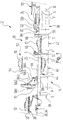
- eine Veranschaulichung verschiedener Komponenten einer Tauchbehandlungsanlage und deren Arbeitsweise in einer schematischen Seitenansicht eines Abschnitts der Tauchbehandlungsanlage;
- Figur 2
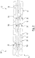
- eine Layoutansicht eines Abschnitts eines ersten Ausführungsbeispiels einer Tauchbehandlungsanlage;
- Figur 3
- eine Layoutansicht eines zweiten Ausführungsbeispiels einer Tauchbehandlungsanlage;
- Figur 4
- eine Layoutansicht eines dritten Ausführungsbeispiels einer Tauchbehandlungsanlage.
- FIG. 1
- an illustration of various components of a dip treatment plant and its operation in a schematic side view of a portion of the dip treatment plant;
- FIG. 2
- a layout view of a portion of a first embodiment of a dip treatment plant;
- FIG. 3
- a layout view of a second embodiment of a dip treatment plant;
- FIG. 4
- a layout view of a third embodiment of a dip treatment plant.
Zunächst wird auf
Die Tauchbehandlungsanlage 12 umfasst eine Tauchbeckenanordnung 14, durch welche die Fahrzeugkarosserien 10 mittels eines insgesamt mit 16 bezeichneten Fördersystems geführt wird.The
Hierzu umfasst das Fördersystem 16 eine Anzahl von Fördereinheiten in Form von mehrachsigen Förderroboter 18 mit jeweils einem Fahrwerk 20 und einen Roboterarm 22, der an seinem vom Fahrwerk abliegenden Ende ein Roboterhandstück 24 trägt, wie es an und für sich bekannt ist. Vorliegend ist das Roboterhandstück 24 als Greiferhandstück ausgebildet.For this purpose, the
In
Die Förderroboter 18 weisen in an und für sich bekannter Art und Weise sechs Bewegungsachsen auf, die mit den Bezugszeichen BA1 bis BA5 und VA bezeichnet und ebenfalls der Übersichtlichkeit halber nur beim Förderroboter 18b gekennzeichnet sind.The conveying
Die Achse VA bildet die Verfahrachse des Förderroboters 18, entlang dieser auf einer Fahrbahn verfahren werden kann, die durch eine Laufbahn 26 vorgegeben ist. Dementsprechend weist jeder Förderroboter 18 neben seiner Verfahrachse VA fünf weitere Bewegungsachsen BA1 bis BA5 auf. Die senkrecht aufeinander stehenden Bewegungsachsen BA1 und BA2 sind dabei dem Roboterhandstück 24 zugeordnet. Die horizontale Bewegungsachse BA3 ist durch ein Gelenk 22a des Roboterarms 22 vorgegeben, wodurch dieser als Knickarm ausgebildet ist. Der Roboterarm 22 seinerseits wird erfindungsgemäß am vom Roboterhandstück 24 abliegenden Ende um die horizontale Bewegungsachse B4 nach oben und unten verschwenkt und um die vertikale Bewegungsachse B5 gegenüber dem Fahrwerk 20 verdreht.The axis VA forms the travel axis of the
Bei einer nicht eigens gezeigten Abwandlung können die Förderroboter 18 auch lediglich fünfachsig ausgebildet sein, wobei die Bewegungsachse BA3 im Roboterarm 22 entfällt und dieser nicht gelenkig, sondern starr ausgebildet ist. In diesem Fall weist der Förderroboter 18 neben der Verfahrachse VA somit vier weitere Bewegungsachsen auf. Die geringere Bewegungsfreiheit gegenüber einem sechsachsigen Förderroboter beim Positionieren einer Fahrzeugkarosserie kann durch ein angepasstes Verfahren entlang der Verfahrachse VA ausgeglichen werden.In a modification not shown specifically, the
Die höchste Beweglichkeit wird erreicht, wenn der Förderroboter sieben Bewegungsachsen aufweist, wie es ebenfalls an und für sich bekannt ist. Im Vergleich zum sechsachsigen Förderroboter 18 ist dann eine weitere Bewegungsachse beim Roboterhandstück 24 vorhanden, die zumindest achsparallel zur Längsachse des Armteils des Roboterarms 22 verläuft, der das Roboterhandstück 24 trägt.The highest mobility is achieved when the conveyor robot has seven axes of motion, as it is also known in and of itself. In comparison to the six-
In
Die Fahrzeugkarosserien 10 kommen über einen Zuführförderer 30 zur Tauchbehandlungsanlage 12, der beim vorliegenden Ausführungsbeispiel als Rollenbahnförderer veranschaulicht ist, wie er aus dem Stand der Technik bekannt ist. Damit die Fahrzeugkarosserien 10 mit diesem Zuführ-Rollenbahnförderer 30 gefördert werden können, sind sie in bekannter Art und Weise auf jeweils einem so genannten Skid 32 befestigt, der auf dem Zuführ-Rollenbahnförderer 30 abläuft.The
Beim vorliegenden Ausführungsbeispiel verbleiben die Fahrzeugkarosserien 10 auf dem jeweiligen Skid 32 befestigt, wenn sie durch die Tauchbehandlungsanlage 12 geführt werden. Damit die Förderroboter 18 ein Skid 32 mit der darauf befestigten Fahrzeugkarosserie 10 aufnehmen können, ist dem Zuführ-Rollenbahnförderer 30 eine Adapterstation 34 zugeordnet, auf welcher Adaptereinheiten 36 bereitgestellt werden, die einerseits von dem Greiferhandstück 24 des Förderroboters 18 gegriffen und andererseits mit dem Skid 32 verbunden werden können.In the present embodiment, the
Bei einer Abwandlung können die Fahrzeugkarosserien 10 auch als solche und ohne Skid 32 durch die Tauchbehandlungsanlage 12 geführt werden. In diesem Fall sind die Adaptereinheiten 36 derart ausgebildet, dass sie einerseits von dem Roboterhandgelenk 24 gegriffen und andererseits unmittelbar mit der Fahrzeugkarosserie 10 verbunden werden können.In a modification, the
Bei einer weiteren Abwandlung kann das Greiferhandstück 24 des Förderroboters 18 auch so an eine zu behandelnde Fahrzeugkarosserie 10 angepasst sein, dass diese direkt von dem Förderroboter 18 aufgenommen werden kann.In a further modification, the
Alternativ zu dem Greifhandstück 24 kann ein Förderroboter 18 auch ein Handstück aufweisen, welches nicht als Greifer ausgebildet ist und an welchem eine Adaptereinheit 36, ein Skid 32 oder eine Fahrzeugkarosserie 10 befestigt werden kann.As an alternative to the gripping
Somit bilden entweder das Handstück 24 oder das Handstück 24 in Verbindung mit dem Adapter 36 eine Befestigungseinrichtung, welche die Fahrzeugkarosserie 10 - entweder unmittelbar oder mittelbar über den Skid 32 - mit dem Förderroboter 18 koppelt.Thus, either the
Die Adaptereinheiten 36 können als starre Verbindungsstrukturen ausgebildet sein, die an Skids 32 oder Fahrzeugkarosserien 10 einer bestimmten Bauart angepasst sind. Alternativ können die Adaptereinheiten 36 aber auch als in ihrer Geometrie veränderbare Koppeleinheiten ausgebildet sein, so dass sie manuell oder über den Förderroboter 18 gesteuert an Skids 32 oder Fahrzeugkarosserien 10 unterschiedlicher Bauart angepasst werden können. In diesem Fall können die Adaptereinheiten 36 stets mit dem Roboterhandstück 24 verbunden sein und müssen nicht ausgetauscht werden, wenn ein von der Bauart eines vorhergehenden Skids 32 abweichender Skids 32 oder eine von der Bauart einer vorhergehenden Fahrzeugkarosserie 10 abweichende Fahrzeugkarosserie 10 vom Förderroboter 18 aufgenommen werden soll.The
Die Tauchbeckenanordnung 14 umfasst Tauchbecken unterschiedlicher Bauart, die auf unterschiedliche Art und Weise mit den Förderrobotern 18 zusammenarbeiten, wobei in
Die Tauchbecken 38, 40 und 42 der Tauchbehandlungsanlage 12 sind jeweils bis zu einem Flüssigkeitsspiegel S mit einer Behandlungsflüssigkeit F gefüllt, deren Art und Zusammensetzung in jedem Tauchbecken 38, 40, 42 jeweils von der Art der gewünschten Behandlung abhängt, die durch ein bestimmtes Tauchbad erfolgen soll, wie es eingangs erläutert wurde.The
Die in
Beim Ein- und Austauchvorgang wird die Fahrzeugkarosserie 10 Dach unten geführt. Durch die Bewegungsfreiheitsgrade des Roboterarms 22 mit dem Roboterhandstück 24 können die Fahrzeugkarosserien 10 mit variablen Bewegungskinematiken durch die Tauchbecken 38 geführt werden. Der jeweils auszuführende Bewegungsablauf kann dabei einerseits von der Art der zu behandelnden Fahrzeugkarosserie und andererseits von der Art des Tauchbades abhängen und individuell vorgegeben werden.When entering and Ausauchvorgang the
Das Auflage-Tauchbecken 40 umfasst eine Halteeinrichtung 44, auf welche ein Skid 32 aufgelegt werden kann, so dass die zugehörige Fahrzeugkarosserie 10 Dach unten vollständig in die Behandlungsflüssigkeit F im Auflage-Tauchbecken 40 eintaucht, wie es in
In diesem Fall wird die Fahrzeugkarosserie 10 mit Skid 32 beim Eintauchvorgang von dem Förderroboter 18 über Kopf gedreht und in die Behandlungsflüssigkeit F im Auflage-Tauchbecken 40 eingetaucht, bis der Skid 32 auf der Halteeinrichtung 44 zu liegen kommt. Eine entsprechende ÜberKopf-Anordnung einer Fahrzeugkarosserie 10 ist in
Dann kann das Roboterhandstück 24 oder die Adaptereinheit 36 von dem Skid 32 getrennt werden und der Förderroboter 18 andere Aufgaben durchführen, während die Fahrzeugkarosserie 10 in dem Auflage-Tauchbecken 40 verweilt. Wenn die Fahrzeugkarosserie 10 die für die entsprechende Behandlung benötigte Zeit in der Behandlungsflüssigkeit F verbracht hat, wird der Skid 32 von demselben oder einem anderen Förderroboter 18 aufgenommen und die Fahrzeugkarosserie 10 aus dem Auflage-Tauchbecken 40 heraus bewegt.Then, the
Wenn eine Adaptereinheit 36 verwendet wird, können die Förderroboter 18 eine Fahrzeugkarosserie 10 jeweils in die Behandlungsflüssigkeit F in einem Standard-Tauchbecken 38 oder einem Auflage-Tauchbecken 40 eintauchen, ohne dass das Handstück 24 des Förderroboters 18 ebenfalls in die jeweilige Behandlungsflüssigkeit F eintauchen muss.When an
Das Hub-/Senk-Tauchbecken 42 umfasst eine Hub-/Senkeinrichtung 46 mit einem für Skids 32 ausgelegten Traggestell 48. Dieses kann in vertikalen Führungsschienen 50 an den Stirnwänden des Hub-/Senk-Tauchbeckens 42 in dessen Innenraum abgesenkt oder aus diesem angehoben werden, was in
Beim vorliegenden Ausführungsbeispiel ist das Traggestell 48 so an das oder die verwendeten Skids 32 angepasst, dass die Fahrzeugkarosserie 10 Dach oben aufgenommen werden kann. Beim Eintauchvorgang übergibt der Förderroboter 18 den Skid 32 mit der Fahrzeugkarosserie 10 oberhalb des Flüssigkeitsspiegels S der Behandlungsflüssigkeit F an das Traggestell 48 und gibt dann den Skid 32 automatisch frei oder wird von diesem getrennt.In the present embodiment, the
Das Traggestell 48 wird dann zusammen mit dem Skid 32 und der darauf befestigten Fahrzeugkarosserie 10 abgesenkt, so dass die Fahrzeugkarosserie 10 in die Behandlungsflüssigkeit F im Hub-/Senk-Tauchbecken 40 eintaucht. Nach der gebotenen Verweildauer in der Behandlungsflüssigkeit F wird das Traggestell 48 wieder nach oben gefahren und die Fahrzeugkarosserie 10 aus der Behandlungsflüssigkeit über deren Flüssigkeitsspiegel S hinaus angehoben. Dann wird der Skid 32 wieder von einem der Förderroboter 18 aufgenommen und die Fahrzeugkarosserie 10 von dem Hub-/Senk-Tauchbecken 40 weg bewegt.The
Nach allen Tauchbehandlungen in einem der Tauchbecken 38, 40 oder 42 verbleibt die behandelte Fahrzeugkarosserie 10 jeweils noch eine gewisse Zeit oberhalb des Flüssigkeitsspiegels S der jeweiligen Behandlungsflüssigkeit, damit die jeweilige Behandlungsflüssigkeit F von der Fahrzeugkarosserie 10 abtropfen kann. Dies ist am Beispiel des Förderroboters 18c gezeigt, welcher eine Fahrzeugkarosserie 10 in einer Dach unten Stellung über dem Tauchbecken 38 hält.After all immersion treatments in one of the
Entlang der Fahrbahn 26 oder 28 der Förderroboter 18 können Pufferzonen vorgesehen sein, von denen in
Mit Hilfe einer oder mehrerer Pufferzonen 52 ist es möglich, dass jede Fahrzeugkarosserie 10 in einer individuellen Reihenfolge durch die vorhandenen Tauchbecken 38, 40, 42 geführt werden kann. Für jede einzelne Fahrzeugkarosserie 10 kann ein individueller Behandlungsablauf in einer Zentralsteuerung abgelegt sein, welche den Förder- und Behandlungsprozess koordiniert.With the aid of one or
Wenn eine Fahrzeugkarosserie 10 alle notwendigen Tauchbecken 38, 40, 42 durchlaufen hat, wird sie an einen Abgabeförderer 56 übergeben, der wie der Zuführförderer 30 beispielsweise als Rollenbahnförderer ausgebildet sein kann. Von dort werden die Fahrzeugkarosserien 10 dann zu weiteren, der Tauchbehandlungsanlage 12 nachfolgenden Behandlungsstationen transportiert.When a
Die jeweilige Fahrbahn 26 oder 28 der Förderroboter 18 ist auf einem Höhenniveau angesiedelt, das im Bereich des oberen Randes der Tauchbecken 38, 40 bzw. 42 liegt. In der Praxis hat sich bewährt, wenn die Fahrbahn 26, 28 jeweils oberhalb des oberen Randes der Tauchbecken 38, 40, 42 angeordnet ist.The
Damit der Förderroboter 18 mit seinem Roboterarm 22 keinen Beckenrand übergreifen muss, ist allgemein ausgedrückt die bezogen auf die Fahrbahn 26 bzw. 28 tiefstliegende horizontale Bewegungsachse des Förderroboters, beim vorliegenden Ausführungsbeispiel also die Bewegungsachse BA4 des Förderroboters 18, oberhalb des oberen Randes der Tauchbecken 38, 40, 42 angesiedelt. Dies kann entweder durch eine entsprechende Höhenlage der Fahrbahn 26 bzw. 28 oberhalb der Beckenränder oder durch eine geeignete Ausbildung des Förderroboters 18 erreicht werden, bei der die Fahrbahn 26 bzw. 28 auch unterhalb des Höhenniveaus der oberen Ränder der Tauchbecken 38, 40, 42 verlaufen kann.So that the
So können die Förderroboter 18 die Tauchbecken 38, 40, 42 gut erreichen und die Fahrzeugkarosserien 10 von oben in ihre Behandlungsposition in den Tauchbecken 38, 40, 42 bringen.Thus, the
Grundsätzlich dienen die Förderroboter 18 des Fördersystems 16 dazu, die Fahrzeugkarosserien 10 zumindest von einem ersten Tauchbecken zu einem zweiten Tauchbecken zu transportieren. Wenn beispielsweise beim Behandlungsablauf zwei Hub-/Senk-Tauchbecken 42 mit jeweils einer Hub-/Senkeinrichtung 46 aufeinander folgen, sind die Förderroboter 18 nicht mit dem Eintauchen und Austauchen der zu behandelnden Fahrzeugkarosserie 10 befasst, sondern verbringen die betreffende Fahrzeugkarosserie 10 lediglich von einem Hub-/Senk-Tauchbecken 42 zum Nächsten.Basically, the
In den
In den
Bei der Tauchbeckenanordnung 14 gemäß
Diese Anordnung der Tauchbecken 38, 40, 42 ist auch bei der Layoutvariante gemäß
Wie bereits eingangs angesprochen wurde, können die Behandlungszonen 60, 62 und 64 verschiedene Tauchbecken umfassen, die von einer Fahrzeugkarosserie 10 für ein übergeordnetes Behandlungsziel durchlaufen werden müssen. Die Behandlungszone 60 sei dementsprechend mit Tauchbecken 38, 40, 42 für eine Reinigung und ein Entfetten der Fahrzeugkarosserien 10, die Behandlungszone 62 mit Tauchbecken 38, 40, 42 für eine Phosphatierung und die Behandlungszone 64 mit Tauchbecken 38, 40, 42 für eine KTL bestückt.As already mentioned, the
Die Behandlungszonen 60 und 62 bzw. 62 und 64 sind durch jeweils einen Übergabeförderer 66a bzw. 66b miteinander verbunden, die z.B. als Rollenbahnförderer ausgebildet sein können. Stattdessen können auch Umsetzroboter vorhanden sein, die stationär sein und mit Zwischenauflagen für die Fahrzeugkarosserien 10 zusammenarbeiten oder verfahrbar sein können.
Wenn eine Fahrzeugkarosserie 10 die erste Behandlungszone 60 durchlaufen und alle dort vorgesehenen Tauchbäder absolviert hat, wird sie von dem Förderroboter 18a an den Übergabeförderer 66a übergeben, von diesem in den Zugriffbereich des Förderroboters 18b in der zweiten Behandlungszone 62 gefördert und dort von dem Förderroboter 18 aufgenommen. Entsprechend erfolgt mittels des Übergabeförderers 66b die Übergabe der Fahrzeugkarosserie 10 von der zweiten Behandlungszone 62 an die dritte Behandlungszone 64, wo die Fahrzeugkarosserie 10 von dem Förderroboter 18c aufgenommen und durch die Tauchbäder geführt wird.When a
Bei der Layoutvariante gemäß
Bei allen oben beschriebenen Layoutvarianten befinden sich Tauchbecken 38, 40, 42 zu beiden Seiten neben der durch die jeweils betrachtete Führungsschiene 28 vorgegebenen Fahrbahn der Förderroboter 18, bei der Layoutvariante nach
Insgesamt kann die Anordnung der Tauchbecken 38, 40, 42 in der Tauchbehandlungsanlage 12 verhältnismäßig frei an die örtlichen Gegebenheiten und daran angepasst werden, ob mehr Raum in der Breite der Anlage oder in Längsrichtung der Anlage zur Verfügung steht.Overall, the arrangement of the
Bei einer nicht eigens gezeigten weiteren Abwandlung können auch Tauchbecken 38, 40, 42 übereinander angeordnet sein. In diesem Fall können gegebenenfalls auch mehrere Fahrbahnen, seien es Laufbahnen 26 oder Führungsschienen 28, übereinander angeordnet sein, die jeweils einer Tauchbeckenanordnung 14 auf einem bestimmten Höhenniveau zugeordnet sind und auf denen sich entsprechend Förderroboter 18 befinden. In diesem Fall können Fahrzeugkarosserien 18 auch von unten nach oben oder von oben nach unten übergeben werden, indem z.B. geeignete Pufferstationen zwischengeschaltet werden.In a further modification not specifically shown,
Claims (8)
- Dipping-treatment installation for vehicle bodies, comprisinga) at least one dipping basin (38, 40, 42) which is fillable with a treatment liquid (F) into which the vehicle bodies (10) to be treated can be dipped;b) a conveying system (16) which can move the vehicle bodies (10) to be treated up to the dipping basin (38, 40, 42), into the interior of the dipping basin (38, 40, 42), out of the dipping basin (38, 40, 42) and away from the latter and which comprises at least one transport unit (18) which carries a fastening device (24; 24, 36) therewith, via which the vehicle body (10) is couplable to the transport unit (18);
wherein:c) the at least one transport unit (18) is a multi-axis conveying robot (18) with a chassis (20), which is movable along a travelling axis (VA), characterized in that the conveying robot (18) comprises a robot arm (22) with an arm joint (22a), which carries the fastening device (24; 24, 36) which is formed by a robot handpiece (24) or by a robot handpiece (24) and an adaptor (36) ;d) the robot handpiece (24) is assigned two movement axes (BA1, BA2) which are perpendicular to each other;e) a movement axis (BA3) is predetermined by the arm joint (22a);f) the robot arm (22) is pivotable upwards and downwards about a horizontal movement axis (BA4) at the end remote from the robot handpiece (24) and is rotatable about a vertical movement axis (BA5) in relation to the chassis (20). - Dipping-treatment installation according to Claim 1, characterized in that the fastening device (24; 24, 36) is configured in such a manner that it is couplable directly to a vehicle body (10) and/or is couplable to a supporting structure (32) which is connected to the vehicle body (10).
- Dipping-treatment installation according to Claim 1 or 2, characterized in that there are a plurality of dipping basins (38, 40, 42) which are arranged on one side or on both sides next to a path of movement (26; 28) of the conveying robot (18).
- Dipping-treatment installation according to one of Claims 1 to 3, characterized in that a horizontal movement axis (BA4) of the conveying robot (18), said movement axis being located at the lowest point with respect to the path of movement (26; 28), is located above the upper edge of the dipping basin or the dipping basins (38, 40, 42).
- Dipping treatment installation according to one of Claims 1 to 4, characterized in that a) there are at least one first treatment zone (60, 62) with a first path of movement (28a, 28b) and a first conveying robot (18a, 18b) and a second treatment zone (62, 64) with a second path of movement (28b, 28c) and a second conveying robot (18b, 18c), to each of which treatment zones at least one dipping basin (38, 40, 42) is assigned;b) a transfer device (66a, 66b) is arranged between the first and the second treatment zone (60, 62, 64), by means of which a vehicle body (10) can be transferred from the first conveying robot (18a, 18b) to the second conveying robot (18b, 18c).
- Dipping-treatment installation according to one of Claims 1 to 5, characterized in that one or more dipping basins (38, 40, 42) which each define a basin longitudinal direction (BL) are arranged in such a manner that their basin longitudinal direction (BL) runs at an angle to the travelling axis (VA) of the conveying robot (18) that is different than 0°.
- Dipping-treatment installation according to Claim 6, characterized in that the angle of the basin longitudinal direction (BL) with respect to the travelling axis (VA) of the conveying robot (18) is 90°.
- Method for operating a dipping-treatment installation for vehicle bodies, in which vehicle bodies (10) to be treated are moved by means of a conveying system (16) up to a dipping basin (38, 40, 42), into the interior of the dipping basin (38, 40, 42), out of the dipping basin (38, 40, 42) and away from the latter,
wherein
vehicle bodies (10) to be treated are transported at least from a first dipping basin (38, 40, 42) to a second dipping basin (38, 40, 42) by means of at least one multi-axis conveying robot (18) with a chassis (20), which is movable along a travelling axis (VA), characterized in that the conveying robot comprises a robot arm (22) with an arm joint (22a), wherein the robot arm (22) carries a fastening device (24; 24, 36) which is formed by a robot handpiece (24) or by a robot handpiece (24) and an adaptor (36),
and wherein the robot handpiece (24) is assigned two movement axes (BA1, BA2) which are perpendicular to each other, a movement axis (BA3) is predetermined by the arm joint (22a), and the robot arm (22) is pivotable upwards and downwards about a horizontal movement axis (BA4) at the end remote from the robot handpiece (24) and is rotatable about a vertical movement axis (BA5) in relation to the chassis (20).
Applications Claiming Priority (2)
| Application Number | Priority Date | Filing Date | Title |
|---|---|---|---|
| DE102011013415.8A DE102011013415B4 (en) | 2011-03-09 | 2011-03-09 | Submersion treatment system for vehicle bodies and method for operating such |
| PCT/EP2012/000867 WO2012119716A1 (en) | 2011-03-09 | 2012-02-29 | Dipping-treatment installation for vehicle bodies, and a method for operating same |
Publications (2)
| Publication Number | Publication Date |
|---|---|
| EP2683634A1 EP2683634A1 (en) | 2014-01-15 |
| EP2683634B1 true EP2683634B1 (en) | 2017-09-06 |
Family
ID=45774151
Family Applications (1)
| Application Number | Title | Priority Date | Filing Date |
|---|---|---|---|
| EP12706486.3A Not-in-force EP2683634B1 (en) | 2011-03-09 | 2012-02-29 | Dipping-treatment installation for vehicle bodies, and a method for operating same |
Country Status (3)
| Country | Link |
|---|---|
| EP (1) | EP2683634B1 (en) |
| DE (1) | DE102011013415B4 (en) |
| WO (1) | WO2012119716A1 (en) |
Cited By (1)
| Publication number | Priority date | Publication date | Assignee | Title |
|---|---|---|---|---|
| DE102022110525A1 (en) | 2021-12-14 | 2023-06-15 | Wenker Gmbh & Co. Kg | Conveyor system, dip treatment installation and method for dip treating a workpiece |
Families Citing this family (5)
| Publication number | Priority date | Publication date | Assignee | Title |
|---|---|---|---|---|
| DE102013012485A1 (en) * | 2013-07-26 | 2015-02-19 | Eisenmann Ag | Process and installation for the surface treatment of vehicle bodies |
| DE202015002578U1 (en) * | 2015-04-08 | 2015-04-28 | Eisenmann Se | Dipping treatment plant for dipping objects |
| CN105314401B (en) * | 2015-11-02 | 2017-12-22 | 天奇自动化工程股份有限公司 | Automatic turning immersion liquid equipment |
| DE102017000639A1 (en) | 2017-01-25 | 2018-07-26 | Audi Ag | Immersion treatment system |
| DE102020128925A1 (en) | 2020-11-03 | 2022-05-05 | Audi Aktiengesellschaft | Method and system for quenching metal components |
Family Cites Families (13)
| Publication number | Priority date | Publication date | Assignee | Title |
|---|---|---|---|---|
| BE758738A (en) * | 1969-11-12 | 1971-04-16 | Strecke Heinz | DEVICE FOR THE HORIZONTAL TRANSPORT, FROM ONE TREATMENT STATION TO ANOTHER, OF WORKPIECES |
| DE2527829C3 (en) * | 1975-06-23 | 1981-07-02 | Eksperimental'no-konstruktorskij i technologičeskij institut avtomobil'noj promyšlennosti, L'vov | Automatic manipulator for production lines |
| JP3388210B2 (en) * | 1999-10-21 | 2003-03-17 | 大日本スクリーン製造株式会社 | Substrate surface treatment equipment |
| DE10103837B4 (en) | 2001-01-29 | 2005-09-29 | EISENMANN Fördertechnik GmbH & Co. KG | Plant for treating, in particular for painting objects, in particular vehicle bodies |
| JP2001308160A (en) * | 2001-03-08 | 2001-11-02 | Dainippon Screen Mfg Co Ltd | Substrate processing device |
| DE10217022A1 (en) * | 2002-04-11 | 2003-11-06 | Cad Fem Gmbh | Device and method for simulating production processes |
| JP4350441B2 (en) * | 2003-07-04 | 2009-10-21 | 本田技研工業株式会社 | Component transportation / mounting method and apparatus |
| JP4925615B2 (en) * | 2005-06-29 | 2012-05-09 | 株式会社大気社 | Transport equipment |
| JP4714160B2 (en) * | 2006-02-17 | 2011-06-29 | 株式会社ダイフク | Penetration shielding structure |
| US7798316B2 (en) * | 2007-04-11 | 2010-09-21 | Chrysler Group Llc | Robotic frame handling system |
| DE102008006170B4 (en) * | 2008-01-26 | 2018-01-04 | Eisenmann Se | Device for handling objects |
| DE102008010401A1 (en) * | 2008-02-21 | 2009-10-01 | Eisenmann Anlagenbau Gmbh & Co. Kg | Monorail system and dip treatment plant with such |
| DE102010005314A1 (en) * | 2010-01-21 | 2010-08-19 | Daimler Ag | Device for mounting e.g. panorama glass roof, at body of e.g. electric vehicle, to transport testing system for fuel of fuel cell system, has transport device moved independent of conveyors in rail-free manner |
-
2011
- 2011-03-09 DE DE102011013415.8A patent/DE102011013415B4/en not_active Expired - Fee Related
-
2012
- 2012-02-29 EP EP12706486.3A patent/EP2683634B1/en not_active Not-in-force
- 2012-02-29 WO PCT/EP2012/000867 patent/WO2012119716A1/en active Application Filing
Non-Patent Citations (1)
| Title |
|---|
| None * |
Cited By (1)
| Publication number | Priority date | Publication date | Assignee | Title |
|---|---|---|---|---|
| DE102022110525A1 (en) | 2021-12-14 | 2023-06-15 | Wenker Gmbh & Co. Kg | Conveyor system, dip treatment installation and method for dip treating a workpiece |
Also Published As
| Publication number | Publication date |
|---|---|
| DE102011013415A1 (en) | 2012-09-13 |
| DE102011013415B4 (en) | 2015-12-17 |
| WO2012119716A1 (en) | 2012-09-13 |
| EP2683634A1 (en) | 2014-01-15 |
Similar Documents
| Publication | Publication Date | Title |
|---|---|---|
| EP2242712B1 (en) | Overhead conveyor system and dip coating line comprising said system | |
| EP2683634B1 (en) | Dipping-treatment installation for vehicle bodies, and a method for operating same | |
| EP1320418B2 (en) | Device and Method for the Surface Treatment of Workpieces | |
| DE102016004484A1 (en) | Process and manufacturing plant for the production of vehicles and surface treatment equipment for the surface treatment of vehicle bodies | |
| DE102012003271B4 (en) | Immersion treatment system | |
| DE602005004379T2 (en) | DEVICE FOR THE TRANSPORT AND POSITIONING OF A MOTOR VEHICLE ASSEMBLY | |
| EP2714496B1 (en) | Apparatus for conveying and plant for surface-treating articles | |
| EP1347926B1 (en) | Treatment plant, in particular for painting objects, in particular vehicle bodies | |
| DE102011100828A1 (en) | Device for transferring vehicle wheels | |
| DE102004024614A1 (en) | Plant and method for conveying workpieces along a treatment path | |
| EP2847065A1 (en) | Processing system for construction units | |
| WO2003076315A1 (en) | System for treating, in particular, cataphoretically immersion painting vehicle bodies | |
| EP1483434B1 (en) | Plant for the treatment, in particular the cataphoretic dip coating of objects, in particular of vehicle chassis | |
| EP2839886A1 (en) | Method and system for treating the surface of motor vehicle bodies | |
| DE19950892B4 (en) | Device for treating the surface of objects | |
| DE10210981B4 (en) | Plant for treating, in particular for cataphoretic dip painting, objects, in particular vehicle bodies | |
| WO2023116975A1 (en) | Conveying system, treatment system and method for treating workpieces | |
| WO2019215015A1 (en) | Dip treatment system and method for the dip treatment of articles, in particular vehicle bodies | |
| DE102015002091B4 (en) | Conveying system for conveying objects and dipping treatment plant with such | |
| DE19954203A1 (en) | Body shell immersion bath chain linkage for road vehicle production line operates with limited power effecting full cycle and is flexible in operation with bodies undergoing tilting action | |
| EP3078616A1 (en) | Dip coating system for dip coating objects | |
| DE10153992A1 (en) | Device and method for surface treatment of workpieces | |
| DE102016219703A1 (en) | Process for the treatment of components | |
| DE10239484A1 (en) | Handling system for vehicle body parts in factory has conveyer which dips each part into several vats of treatment and coating fluids in turn using carriage with rotatable clamp | |
| DD276629A1 (en) | DEVICE FOR THE AUTOMATIC SURFACE TREATMENT OF SMALL CONTAINERS AND ITEMS |
Legal Events
| Date | Code | Title | Description |
|---|---|---|---|
| PUAI | Public reference made under article 153(3) epc to a published international application that has entered the european phase |
Free format text: ORIGINAL CODE: 0009012 |
|
| 17P | Request for examination filed |
Effective date: 20130801 |
|
| AK | Designated contracting states |
Kind code of ref document: A1 Designated state(s): AL AT BE BG CH CY CZ DE DK EE ES FI FR GB GR HR HU IE IS IT LI LT LU LV MC MK MT NL NO PL PT RO RS SE SI SK SM TR |
|
| DAX | Request for extension of the european patent (deleted) | ||
| RAP1 | Party data changed (applicant data changed or rights of an application transferred) |
Owner name: EISENMANN SE |
|
| 17Q | First examination report despatched |
Effective date: 20160118 |
|
| GRAP | Despatch of communication of intention to grant a patent |
Free format text: ORIGINAL CODE: EPIDOSNIGR1 |
|
| STAA | Information on the status of an ep patent application or granted ep patent |
Free format text: STATUS: GRANT OF PATENT IS INTENDED |
|
| INTG | Intention to grant announced |
Effective date: 20170418 |
|
| GRAS | Grant fee paid |
Free format text: ORIGINAL CODE: EPIDOSNIGR3 |
|
| GRAA | (expected) grant |
Free format text: ORIGINAL CODE: 0009210 |
|
| STAA | Information on the status of an ep patent application or granted ep patent |
Free format text: STATUS: THE PATENT HAS BEEN GRANTED |
|
| AK | Designated contracting states |
Kind code of ref document: B1 Designated state(s): AL AT BE BG CH CY CZ DE DK EE ES FI FR GB GR HR HU IE IS IT LI LT LU LV MC MK MT NL NO PL PT RO RS SE SI SK SM TR |
|
| REG | Reference to a national code |
Ref country code: GB Ref legal event code: FG4D Free format text: NOT ENGLISH |
|
| REG | Reference to a national code |
Ref country code: CH Ref legal event code: EP Ref country code: AT Ref legal event code: REF Ref document number: 925635 Country of ref document: AT Kind code of ref document: T Effective date: 20170915 |
|
| REG | Reference to a national code |
Ref country code: IE Ref legal event code: FG4D Free format text: LANGUAGE OF EP DOCUMENT: GERMAN |
|
| REG | Reference to a national code |
Ref country code: DE Ref legal event code: R096 Ref document number: 502012011189 Country of ref document: DE |
|
| REG | Reference to a national code |
Ref country code: NL Ref legal event code: MP Effective date: 20170906 |
|
| REG | Reference to a national code |
Ref country code: LT Ref legal event code: MG4D |
|
| PG25 | Lapsed in a contracting state [announced via postgrant information from national office to epo] |
Ref country code: SE Free format text: LAPSE BECAUSE OF FAILURE TO SUBMIT A TRANSLATION OF THE DESCRIPTION OR TO PAY THE FEE WITHIN THE PRESCRIBED TIME-LIMIT Effective date: 20170906 Ref country code: HR Free format text: LAPSE BECAUSE OF FAILURE TO SUBMIT A TRANSLATION OF THE DESCRIPTION OR TO PAY THE FEE WITHIN THE PRESCRIBED TIME-LIMIT Effective date: 20170906 Ref country code: FI Free format text: LAPSE BECAUSE OF FAILURE TO SUBMIT A TRANSLATION OF THE DESCRIPTION OR TO PAY THE FEE WITHIN THE PRESCRIBED TIME-LIMIT Effective date: 20170906 Ref country code: NO Free format text: LAPSE BECAUSE OF FAILURE TO SUBMIT A TRANSLATION OF THE DESCRIPTION OR TO PAY THE FEE WITHIN THE PRESCRIBED TIME-LIMIT Effective date: 20171206 Ref country code: LT Free format text: LAPSE BECAUSE OF FAILURE TO SUBMIT A TRANSLATION OF THE DESCRIPTION OR TO PAY THE FEE WITHIN THE PRESCRIBED TIME-LIMIT Effective date: 20170906 |
|
| REG | Reference to a national code |
Ref country code: FR Ref legal event code: PLFP Year of fee payment: 7 |
|
| PG25 | Lapsed in a contracting state [announced via postgrant information from national office to epo] |
Ref country code: GR Free format text: LAPSE BECAUSE OF FAILURE TO SUBMIT A TRANSLATION OF THE DESCRIPTION OR TO PAY THE FEE WITHIN THE PRESCRIBED TIME-LIMIT Effective date: 20171207 Ref country code: LV Free format text: LAPSE BECAUSE OF FAILURE TO SUBMIT A TRANSLATION OF THE DESCRIPTION OR TO PAY THE FEE WITHIN THE PRESCRIBED TIME-LIMIT Effective date: 20170906 Ref country code: RS Free format text: LAPSE BECAUSE OF FAILURE TO SUBMIT A TRANSLATION OF THE DESCRIPTION OR TO PAY THE FEE WITHIN THE PRESCRIBED TIME-LIMIT Effective date: 20170906 Ref country code: BG Free format text: LAPSE BECAUSE OF FAILURE TO SUBMIT A TRANSLATION OF THE DESCRIPTION OR TO PAY THE FEE WITHIN THE PRESCRIBED TIME-LIMIT Effective date: 20171206 Ref country code: ES Free format text: LAPSE BECAUSE OF FAILURE TO SUBMIT A TRANSLATION OF THE DESCRIPTION OR TO PAY THE FEE WITHIN THE PRESCRIBED TIME-LIMIT Effective date: 20170906 |
|
| PG25 | Lapsed in a contracting state [announced via postgrant information from national office to epo] |
Ref country code: NL Free format text: LAPSE BECAUSE OF FAILURE TO SUBMIT A TRANSLATION OF THE DESCRIPTION OR TO PAY THE FEE WITHIN THE PRESCRIBED TIME-LIMIT Effective date: 20170906 |
|
| PG25 | Lapsed in a contracting state [announced via postgrant information from national office to epo] |
Ref country code: CZ Free format text: LAPSE BECAUSE OF FAILURE TO SUBMIT A TRANSLATION OF THE DESCRIPTION OR TO PAY THE FEE WITHIN THE PRESCRIBED TIME-LIMIT Effective date: 20170906 Ref country code: PL Free format text: LAPSE BECAUSE OF FAILURE TO SUBMIT A TRANSLATION OF THE DESCRIPTION OR TO PAY THE FEE WITHIN THE PRESCRIBED TIME-LIMIT Effective date: 20170906 Ref country code: RO Free format text: LAPSE BECAUSE OF FAILURE TO SUBMIT A TRANSLATION OF THE DESCRIPTION OR TO PAY THE FEE WITHIN THE PRESCRIBED TIME-LIMIT Effective date: 20170906 |
|
| PG25 | Lapsed in a contracting state [announced via postgrant information from national office to epo] |
Ref country code: SK Free format text: LAPSE BECAUSE OF FAILURE TO SUBMIT A TRANSLATION OF THE DESCRIPTION OR TO PAY THE FEE WITHIN THE PRESCRIBED TIME-LIMIT Effective date: 20170906 Ref country code: IS Free format text: LAPSE BECAUSE OF FAILURE TO SUBMIT A TRANSLATION OF THE DESCRIPTION OR TO PAY THE FEE WITHIN THE PRESCRIBED TIME-LIMIT Effective date: 20180106 Ref country code: SM Free format text: LAPSE BECAUSE OF FAILURE TO SUBMIT A TRANSLATION OF THE DESCRIPTION OR TO PAY THE FEE WITHIN THE PRESCRIBED TIME-LIMIT Effective date: 20170906 Ref country code: EE Free format text: LAPSE BECAUSE OF FAILURE TO SUBMIT A TRANSLATION OF THE DESCRIPTION OR TO PAY THE FEE WITHIN THE PRESCRIBED TIME-LIMIT Effective date: 20170906 |
|
| REG | Reference to a national code |
Ref country code: DE Ref legal event code: R097 Ref document number: 502012011189 Country of ref document: DE |
|
| PLBE | No opposition filed within time limit |
Free format text: ORIGINAL CODE: 0009261 |
|
| STAA | Information on the status of an ep patent application or granted ep patent |
Free format text: STATUS: NO OPPOSITION FILED WITHIN TIME LIMIT |
|
| PG25 | Lapsed in a contracting state [announced via postgrant information from national office to epo] |
Ref country code: DK Free format text: LAPSE BECAUSE OF FAILURE TO SUBMIT A TRANSLATION OF THE DESCRIPTION OR TO PAY THE FEE WITHIN THE PRESCRIBED TIME-LIMIT Effective date: 20170906 |
|
| 26N | No opposition filed |
Effective date: 20180607 |
|
| PG25 | Lapsed in a contracting state [announced via postgrant information from national office to epo] |
Ref country code: SI Free format text: LAPSE BECAUSE OF FAILURE TO SUBMIT A TRANSLATION OF THE DESCRIPTION OR TO PAY THE FEE WITHIN THE PRESCRIBED TIME-LIMIT Effective date: 20170906 |
|
| REG | Reference to a national code |
Ref country code: CH Ref legal event code: PL |
|
| PG25 | Lapsed in a contracting state [announced via postgrant information from national office to epo] |
Ref country code: MT Free format text: LAPSE BECAUSE OF FAILURE TO SUBMIT A TRANSLATION OF THE DESCRIPTION OR TO PAY THE FEE WITHIN THE PRESCRIBED TIME-LIMIT Effective date: 20170906 Ref country code: MC Free format text: LAPSE BECAUSE OF FAILURE TO SUBMIT A TRANSLATION OF THE DESCRIPTION OR TO PAY THE FEE WITHIN THE PRESCRIBED TIME-LIMIT Effective date: 20170906 |
|
| GBPC | Gb: european patent ceased through non-payment of renewal fee |
Effective date: 20180228 |
|
| REG | Reference to a national code |
Ref country code: BE Ref legal event code: MM Effective date: 20180228 |
|
| PG25 | Lapsed in a contracting state [announced via postgrant information from national office to epo] |
Ref country code: LU Free format text: LAPSE BECAUSE OF NON-PAYMENT OF DUE FEES Effective date: 20180228 Ref country code: CH Free format text: LAPSE BECAUSE OF NON-PAYMENT OF DUE FEES Effective date: 20180228 Ref country code: LI Free format text: LAPSE BECAUSE OF NON-PAYMENT OF DUE FEES Effective date: 20180228 |
|
| REG | Reference to a national code |
Ref country code: IE Ref legal event code: MM4A |
|
| PG25 | Lapsed in a contracting state [announced via postgrant information from national office to epo] |
Ref country code: IE Free format text: LAPSE BECAUSE OF NON-PAYMENT OF DUE FEES Effective date: 20180228 |
|
| PG25 | Lapsed in a contracting state [announced via postgrant information from national office to epo] |
Ref country code: BE Free format text: LAPSE BECAUSE OF NON-PAYMENT OF DUE FEES Effective date: 20180228 Ref country code: GB Free format text: LAPSE BECAUSE OF NON-PAYMENT OF DUE FEES Effective date: 20180228 |
|
| REG | Reference to a national code |
Ref country code: AT Ref legal event code: MM01 Ref document number: 925635 Country of ref document: AT Kind code of ref document: T Effective date: 20180228 |
|
| PG25 | Lapsed in a contracting state [announced via postgrant information from national office to epo] |
Ref country code: AT Free format text: LAPSE BECAUSE OF NON-PAYMENT OF DUE FEES Effective date: 20180228 |
|
| PG25 | Lapsed in a contracting state [announced via postgrant information from national office to epo] |
Ref country code: TR Free format text: LAPSE BECAUSE OF FAILURE TO SUBMIT A TRANSLATION OF THE DESCRIPTION OR TO PAY THE FEE WITHIN THE PRESCRIBED TIME-LIMIT Effective date: 20170906 |
|
| PGFP | Annual fee paid to national office [announced via postgrant information from national office to epo] |
Ref country code: IT Payment date: 20200225 Year of fee payment: 9 Ref country code: DE Payment date: 20200219 Year of fee payment: 9 |
|
| PG25 | Lapsed in a contracting state [announced via postgrant information from national office to epo] |
Ref country code: PT Free format text: LAPSE BECAUSE OF FAILURE TO SUBMIT A TRANSLATION OF THE DESCRIPTION OR TO PAY THE FEE WITHIN THE PRESCRIBED TIME-LIMIT Effective date: 20170906 Ref country code: HU Free format text: LAPSE BECAUSE OF FAILURE TO SUBMIT A TRANSLATION OF THE DESCRIPTION OR TO PAY THE FEE WITHIN THE PRESCRIBED TIME-LIMIT; INVALID AB INITIO Effective date: 20120229 |
|
| PG25 | Lapsed in a contracting state [announced via postgrant information from national office to epo] |
Ref country code: MK Free format text: LAPSE BECAUSE OF NON-PAYMENT OF DUE FEES Effective date: 20170906 Ref country code: CY Free format text: LAPSE BECAUSE OF FAILURE TO SUBMIT A TRANSLATION OF THE DESCRIPTION OR TO PAY THE FEE WITHIN THE PRESCRIBED TIME-LIMIT Effective date: 20170906 |
|
| PGFP | Annual fee paid to national office [announced via postgrant information from national office to epo] |
Ref country code: FR Payment date: 20200219 Year of fee payment: 9 |
|
| PG25 | Lapsed in a contracting state [announced via postgrant information from national office to epo] |
Ref country code: AL Free format text: LAPSE BECAUSE OF FAILURE TO SUBMIT A TRANSLATION OF THE DESCRIPTION OR TO PAY THE FEE WITHIN THE PRESCRIBED TIME-LIMIT Effective date: 20170906 |
|
| REG | Reference to a national code |
Ref country code: DE Ref legal event code: R119 Ref document number: 502012011189 Country of ref document: DE |
|
| PG25 | Lapsed in a contracting state [announced via postgrant information from national office to epo] |
Ref country code: DE Free format text: LAPSE BECAUSE OF NON-PAYMENT OF DUE FEES Effective date: 20210901 Ref country code: FR Free format text: LAPSE BECAUSE OF NON-PAYMENT OF DUE FEES Effective date: 20210228 |
|
| PG25 | Lapsed in a contracting state [announced via postgrant information from national office to epo] |
Ref country code: IT Free format text: LAPSE BECAUSE OF NON-PAYMENT OF DUE FEES Effective date: 20210301 |