EP2683435B1 - Dispositifs pour l'irrigation aseptique, l'échantillonnage d'urine et la régulation de l'écoulement d'urine d'une vessie cathétérisée - Google Patents
Dispositifs pour l'irrigation aseptique, l'échantillonnage d'urine et la régulation de l'écoulement d'urine d'une vessie cathétérisée Download PDFInfo
- Publication number
- EP2683435B1 EP2683435B1 EP12776605.3A EP12776605A EP2683435B1 EP 2683435 B1 EP2683435 B1 EP 2683435B1 EP 12776605 A EP12776605 A EP 12776605A EP 2683435 B1 EP2683435 B1 EP 2683435B1
- Authority
- EP
- European Patent Office
- Prior art keywords
- port
- valve
- irrigation
- urine
- syringe
- Prior art date
- Legal status (The legal status is an assumption and is not a legal conclusion. Google has not performed a legal analysis and makes no representation as to the accuracy of the status listed.)
- Not-in-force
Links
- 210000002700 urine Anatomy 0.000 title claims description 103
- 238000003973 irrigation Methods 0.000 title claims description 78
- 230000002262 irrigation Effects 0.000 title claims description 78
- 238000005070 sampling Methods 0.000 title description 9
- 230000002485 urinary effect Effects 0.000 claims description 31
- 239000012530 fluid Substances 0.000 claims description 29
- 230000007246 mechanism Effects 0.000 claims description 14
- 238000004891 communication Methods 0.000 claims description 8
- 239000012528 membrane Substances 0.000 claims description 7
- 238000007789 sealing Methods 0.000 claims description 7
- 230000008719 thickening Effects 0.000 claims description 5
- 230000007423 decrease Effects 0.000 claims description 4
- 238000011012 sanitization Methods 0.000 claims description 3
- 238000000034 method Methods 0.000 description 21
- 241000894006 Bacteria Species 0.000 description 11
- 208000015181 infectious disease Diseases 0.000 description 4
- 239000000463 material Substances 0.000 description 4
- 206010003629 Atonic urinary bladder Diseases 0.000 description 3
- 238000005516 engineering process Methods 0.000 description 3
- 238000003780 insertion Methods 0.000 description 3
- 230000037431 insertion Effects 0.000 description 3
- 230000007774 longterm Effects 0.000 description 3
- 206010048994 Bladder spasm Diseases 0.000 description 2
- LFQSCWFLJHTTHZ-UHFFFAOYSA-N Ethanol Chemical compound CCO LFQSCWFLJHTTHZ-UHFFFAOYSA-N 0.000 description 2
- 206010072064 Exposure to body fluid Diseases 0.000 description 2
- 208000005392 Spasm Diseases 0.000 description 2
- 239000004599 antimicrobial Substances 0.000 description 2
- 230000032770 biofilm formation Effects 0.000 description 2
- 238000013461 design Methods 0.000 description 2
- 238000010586 diagram Methods 0.000 description 2
- 230000036541 health Effects 0.000 description 2
- 239000004816 latex Substances 0.000 description 2
- 229920000126 latex Polymers 0.000 description 2
- 239000007788 liquid Substances 0.000 description 2
- 229920001296 polysiloxane Polymers 0.000 description 2
- 239000010832 regulated medical waste Substances 0.000 description 2
- 238000012549 training Methods 0.000 description 2
- 208000019206 urinary tract infection Diseases 0.000 description 2
- 239000011800 void material Substances 0.000 description 2
- 206010003694 Atrophy Diseases 0.000 description 1
- 201000004538 Bacteriuria Diseases 0.000 description 1
- 208000036828 Device occlusion Diseases 0.000 description 1
- 208000019462 Occupational injury Diseases 0.000 description 1
- 230000004075 alteration Effects 0.000 description 1
- CKMXBZGNNVIXHC-UHFFFAOYSA-L ammonium magnesium phosphate hexahydrate Chemical compound [NH4+].O.O.O.O.O.O.[Mg+2].[O-]P([O-])([O-])=O CKMXBZGNNVIXHC-UHFFFAOYSA-L 0.000 description 1
- 229960005475 antiinfective agent Drugs 0.000 description 1
- 230000001174 ascending effect Effects 0.000 description 1
- 230000037444 atrophy Effects 0.000 description 1
- 230000001580 bacterial effect Effects 0.000 description 1
- 230000003115 biocidal effect Effects 0.000 description 1
- 230000000903 blocking effect Effects 0.000 description 1
- 210000004369 blood Anatomy 0.000 description 1
- 239000008280 blood Substances 0.000 description 1
- 210000001124 body fluid Anatomy 0.000 description 1
- 239000010839 body fluid Substances 0.000 description 1
- 238000009395 breeding Methods 0.000 description 1
- 230000001488 breeding effect Effects 0.000 description 1
- 230000008859 change Effects 0.000 description 1
- 230000006835 compression Effects 0.000 description 1
- 238000007906 compression Methods 0.000 description 1
- 238000011109 contamination Methods 0.000 description 1
- 238000012864 cross contamination Methods 0.000 description 1
- 239000013078 crystal Substances 0.000 description 1
- 230000001419 dependent effect Effects 0.000 description 1
- 230000000881 depressing effect Effects 0.000 description 1
- 210000003811 finger Anatomy 0.000 description 1
- 239000006260 foam Substances 0.000 description 1
- 239000010781 infectious medical waste Substances 0.000 description 1
- 229910052500 inorganic mineral Inorganic materials 0.000 description 1
- 230000007794 irritation Effects 0.000 description 1
- 238000012423 maintenance Methods 0.000 description 1
- 230000014759 maintenance of location Effects 0.000 description 1
- 239000011707 mineral Substances 0.000 description 1
- 239000000203 mixture Substances 0.000 description 1
- 210000003205 muscle Anatomy 0.000 description 1
- 244000052769 pathogen Species 0.000 description 1
- 230000035790 physiological processes and functions Effects 0.000 description 1
- 239000004033 plastic Substances 0.000 description 1
- 238000003825 pressing Methods 0.000 description 1
- 230000008569 process Effects 0.000 description 1
- 150000003839 salts Chemical class 0.000 description 1
- 239000007921 spray Substances 0.000 description 1
- 229910052567 struvite Inorganic materials 0.000 description 1
- 230000008961 swelling Effects 0.000 description 1
- 210000003813 thumb Anatomy 0.000 description 1
Images


Classifications
-
- A—HUMAN NECESSITIES
- A61—MEDICAL OR VETERINARY SCIENCE; HYGIENE
- A61B—DIAGNOSIS; SURGERY; IDENTIFICATION
- A61B10/00—Other methods or instruments for diagnosis, e.g. instruments for taking a cell sample, for biopsy, for vaccination diagnosis; Sex determination; Ovulation-period determination; Throat striking implements
- A61B10/0045—Devices for taking samples of body liquids
- A61B10/007—Devices for taking samples of body liquids for taking urine samples
Definitions
- This invention relates to systems to assist with the irrigation, urine sampling, and drainage of the catheterized bladder, and more particularly, but not limited to, aseptic systems to assist with improved irrigation, urine sampling, and drainage of the catheterized bladder.
- a urinary catheter drainage system is made up of the catheter itself which is inserted into the bladder, and the urine collection device which attaches to the catheter with a tubing and collects the urine into some type of receptacle depending on its purpose.
- a urine collection device is a bedside drainage bag, which is usually a tube connected to the catheter leading to a large bag that hangs on the bedside to collect the urine.
- a leg bag which is worn when a patient is up and around and is a shorter tube attached to a smaller bag which is attached to the leg and collects urine.
- the complications associated with catheterization include, catheter associated urinary tract infections (CAUTI's), blockage, (due to struvite or biofilm formation), bladder atony, (causing a short term or permanent inability to void), bladder spasms, and thickening of the bladder wall from long term use.
- CAUTI's catheter associated urinary tract infections
- blockage due to struvite or biofilm formation
- bladder atony due to struvite or biofilm formation
- bladder atony due to struvite or biofilm formation
- bladder atony due to struvite or biofilm formation
- bladder atony due to struvite or biofilm formation
- bladder atony due to struvite or biofilm formation
- bladder spasms causing a short term or permanent inability to void
- thickening of the bladder wall from long term use are examples of the bladder wall from long term use.
- CAUTI's About 30 % of CAUTI's are shown to be caused by intraluminal bacterial biofilm formation.
- the primary way bacteria enter the inner lumen to cause infection is by entering the drainage end of the catheter and ascending the inner lumen to the bladder.
- the 2009 CDC Healthcare Infection Control Practices Advisory Committee (HICPAH) recommended a closed urinary drainage system with all catheters as a high priority recommendation, essential for all healthcare organizations caring for patients with catheters. They found both older and more recent data indicating that disconnection of the urine collection device from the catheter is a risk factor for bacteriuria.
- the catheter In order to maintain a closed urinary drainage system, the catheter must not be disconnected from the urine collection device. The most common reason for disconnecting the catheter from the urine collection device is when the catheter needs to be irrigated. Many catheters need to be irrigated several times a day exposing the patient to infection and the clinician to bio-hazardous waste up to several times a day.
- Russo U.S. Patent Application Pub. No. US 2006/0064065 discloses a closed system irrigation connector for urinary catheters which allows for a closed irrigation of the catheter wherein a silicone diaphragm opens when an irrigation device is attached, and closes when it is removed. But the device of Russo does not provide for an aseptic irrigation procedure. In order to maintain an aseptic closed system, anything entering said system must be free of bacteria. This means that the system must have entrance portals that are closed while not being accessed and that are fully sanitizable prior to access.
- the surface In order to effectively sanitize a surface, the surface must be easily and fully accessible to apply the needed friction and anti-infective agent.
- the surface must not have crevices or difficult to reach places where bacteria can the friction and antimicrobial agent.
- the plastic entrance port disclosed by Russo does not have a flat, easily sanitizable surface, but has a crevice that cannot be effectively sanitized. Bacteria hiding on this un-sanitizable surface can enter the system during irrigation and infect the patient.
- Catheter blockage is another problem with "constant drain” catheter systems caused by the buildup of biofilm and salt crystals at the opening of the catheter. Much like a stalactite, the high pH, high mineral fluid in the neck of the bladder provides the perfect environment for this to occur.
- Bladder spasms can be caused by several factors. The most frequent cause is CAUTI as already discussed above. The bladder wall becomes irritated and even swells and spasm occurs. The loss of normal stretching and contracting of the detrusor can also cause spasm. Irritation from highly concentrated, and high pH urine could also be factor. Bladder wall thickening has also been observed in long-term catheterizations and may be a result of the increasing. Catheter related bladder atony is another complication associated with not allowing the bladder to fill and empty. When the bladder no longer fills and empties in a normal fashion, the detrusor muscle can atrophy causing a temporary or even permanent inability to void after catheterization. These problems could be solved, at least in part by allowing the bladder to fill and drain in a more normal fashion.
- a system, method, and apparatus is needed that allows for aseptic irrigation and urine sampling while maintaining a closed system, and allows for control of urine flow, allowing the bladder to fill and empty as needed or prescribed.
- US 3 965 910 A discloses a three-way urinary irrigation valve for use with a catheter.
- the valve is movable from a first position in which long term drainage takes place to a second position in which irrigating liquid can be introduced to a bladder, all while maintaining a closed system.
- the urinary irrigation valve includes a housing defining a first passage having an inlet leading to a bladder and an outlet leading to a drainage bag, and a second passage angularly disposed relative to the first passage and having an inlet at one end and an opposite closed end.
- a valve gate disposed in the second passage controls the flow of liquids between the inlet and outlet in the first passage, and between the inlet in the first passage and the second passage.
- An open-topped cap sealingly engages the housing adjacent the end of the second passage having the inlet.
- a resilient means normally biases the valve gate into a first position in which the valve gate cooperates with the cap to block flow through the second passage and permit flow between the inlet and outlet.
- an irrigating syringe can be inserted through the opening in the cap to act on the valve gate. The valve gate thereby assumes a second position in which flow to the outlet in the first passage is blocked, and a passage is defined between the second passage and the inlet of the first passage.
- the disclosed apparatus also referred to for the purposes of easy reference only, as a Port and Valve Assembly, allows for aseptic irrigation and urine sampling of the catheterized bladder without disconnecting the catheter from the drainage bag by providing a sanitizable self closing port and allowing for bypassing of the drainage bag during irrigation.
- An irrigation syringe, irrigating device or urine sampling device can be inserted into a self closing port on the apparatus to irrigate or urine sample the bladder without disconnection of the catheter from the urine collection device, and the bladder can be irrigated or urine sampled while maintaining a closed, aseptic system.
- the port closes.
- the flat closed surface of the port is easily sanitizable with standard medical sanitizer such as 70% alcohol so bacteria cannot enter the system when a device is attached. This allows for aseptic access to the interior of the urinary catheter system so that irrigation can be performed without contamination of the urinary drainage system by bacteria, or exposure to body fluids and infectious waste.
- the apparatus of system employs an inner mechanism which shuts the flow of fluid to the urine collection device while an irrigation syringe, irrigation device, or collection device is inserted in the port.
- This mechanism allows for effective irrigation and urine sampling of the catheter and bladder without fluid or air being shunted into or pulled from the drainage collection device.
- Shutting flow off from the urine collection device is essential for irrigating a catheter while attached to the urine collection device, otherwise fluid would flow into the collection device and not the catheter being irrigated.
- the enhanced system disclosed also makes the collection of urine samples easy by sealing the urine collection device end, and allowing for suction of urine from the bladder.
- an externally controlled mechanism to shut off the flow of urine from the bladder to the urine collection device for a prescribed adjustable period of time, enabling the bladder to fill and empty in a more normal fashion.
- This feature is important because it allows clinicians to set the amount of time for bladder filling, without worrying about releasing the urine at a particular time, as it is done automatically, an important safety and convenience feature.
- This feature also allows for bladder training of patients, allowing for increased increments of time in which the bladder can fill with urine, thus slowly training the bladder to hold more urine before needing to empty.
- the improved utilities of the system and apparatus can decrease the chance of urinary tract infection, bladder atony, decrease the risk of blood and body fluid exposure, and greatly simplify the procedure of bladder irrigation of the catheterized patient.
- a method of irrigating a urinary catheter including the steps of: draining urine from an indwelling urinary catheter through a catheter connector port, a channel and out through a urine exit port; simultaneously opening an irrigation port and closing off flow to the urine exit port; and injecting irrigation fluid through the irrigation port, the channel, the catheter connector port and into the catheter.
- the irrigation port surface is sanitized prior to insertion of the irrigation syringe.
- the method also includes the step of simultaneously closing the irrigation port and opening the urine exit port, thereby allowing urine to drain from the indwelling urinary catheter through the channel and out the urine exit port.
- the step of simultaneously opening the irrigation port and closing the urine exit port includes the step of moving a valve from a first position in which the urine exit port is in fluid communication with the catheter connector port to a second position in which the urine exit port is not in fluid communication with the catheter connector port.
- the moving step may include the step of moving the valve with a distal tip of a syringe.
- the method may also include the step of inserting the syringe through a self-sealing opening in the irrigation port.
- the step of simultaneously opening the irrigation port and closing the urine exit port includes the step of inserting a syringe through the irrigation port and into a valve. In some such methods, the step of simultaneously opening the irrigation port and closing the urine exit port further includes the step of seating an outside surface of the syringe in a valve seat of the valve.
- a method of operating a urinary catheter system including the following steps: establishing flow of urine from an indwelling urinary catheter through a connector and into a drainage bag; actuating a valve to stop the urine flow; and permitting the valve to automatically open after a time period without operator intervention.
- the actuating step includes the step of expanding a balloon to block flow through the connector.
- the permitting step includes the step of permitting the balloon to deflate.
- the expanding step includes the step of compressing a valve actuation chamber.
- the expanding step includes the step of injecting fluid into the balloon with a syringe.
- a method of operating a urinary catheter system including the following steps: establishing flow of urine from an indwelling urinary catheter through a connector and valve opening and into a urine drainage connector; inflating a balloon manually to stop the urine flow through the valve opening and drainage connector; and deflating the balloon manually to allow urine to flow through the valve opening and drainage connector.
- Figures 1 and 2 are illustrations of a self closing port and valve assembly 10 according to one embodiment of the present invention.
- the device has a fully sanitizable self closing irrigation port 12 that allows a urinary catheter to remain attached to a urine collection device while being irrigated without disconnecting the urine collection device drainage tubing 14 from the urinary catheter (not shown).
- This allows for an aseptic, closed system, which keeps bacteria from entering the catheter and also prevents exposure to body fluids during the irrigation or sampling process.
- the self closing port and valve assembly 10 could be located in numerous places on a urinary catheter drainage system. For instance, it could be a part of a urinary catheter itself. It could be a separate device that connects between the catheter and the drainage bag, or it could be a part of the urine collection device. In the embodiment of Figures 1 and 2 , it is a part of the urine collection device, and is located at the junction between the catheter connector port 7 in the catheter connector 11 and the urine exit port 8 in the drainage tube 14 which drains urine from the catheter into the urine collection device.
- an internal valve 15 has a tension spring 17.
- the spring tension keeps the internal valve biased in a first position in which a urine exit port 18 is open to the urine drainage tube 14.
- Spring 17 can be, for example, a torsion spring, leaf spring or any other spring or spring-like element. Insertion of a catheter tip irrigation syringe or other similar device 13 into the self closing irrigation port 12 pushes the internal valve 15 to a second position against the urine exit port to the urine collection device drainage tube 14, closing it off and bypassing any flow to the drainage tube while keeping the irrigation port open.
- the valve 15 is fashioned so that a portion of it protrudes into the path of a device 13 inserted into the self closing irrigation port 12.
- the device inserted into the port pushes the protruding portion of the valve in the direction of the urine exit port, closing the valve when the device is inserted into the irrigation port.
- This automatically shuts off the flow of fluid and air to the drainage bag allowing for irrigation of the catheter and bladder without the irrigation fluid entering the drainage tube.
- the spring 17 moves the valve back to the open position to allow urine to flow from the catheter, into the urine collection device and to the drainage collection receptacle.
- a port and valve assembly 10 also has a valve control mechanism 16 to externally shut the valve 15 without the insertion of a syringe or other object into the port 17. This would allow the valve 15 to be closed even when not irrigating or collecting samples from the catheter. Keeping the valve closed would stop the flow of urine from the bladder to the urine collection device drainage tube 14, and allow the bladder to fill with urine, an important physiological function that is normally inhibited in state of the art urinary catheter systems.
- the valve control mechanism 16 may be designed in such a way as to allow for the valve to stay closed for a specific prescribed and adjustable amount of time, allowing for the bladder to fill for a prescribed amount of time and then empty when that time period ends. Examples of the valve control mechanism are described below.
- FIG 3 is an illustration of an alternative embodiment of the port and valve assembly 10'.
- a syringe is not inserted through a self closing port, and fluid 20 is free to flow through an internal valve 31 through an opening in the valve 30.
- the flow of fluid to the drainage bag is shut off when an irrigation syringe is inserted into the port and valve assembly by means of an internal valve 31 which mates with the tip of the irrigation syringe when inserted.
- the tip of the irrigation syringe fits snugly into the internal valve, sealing flow of fluid or air from the drainage bag.
- the internal valve 31 in the embodiment of Figure 3 and Figure 4 is made by a thickening in the wall of the port and valve assembly, which decreases the diameter of the channel, forming the valve opening 30.
- the internal valve 31 created by the thickened wall may in some embodiments be lined with a flexible material such as foam, latex, or silicone to form a valve seat 32 adapted to cooperate with an exterior surface of the syringe.
- FIG. 5 shows the self closing irrigation port 12 in more detail.
- Irrigation port 12 has a self sealing membrane 9 made of latex or other highly flexible and pliable material.
- the membrane has a small pliable hole 23 within in the center which runs from the external portion to the internal portion.
- the pliable hole 23 spreads open and the irrigation device can be passed through the membrane to the internal portion of the port.
- the opening in the port closes tightly, forming a seal which keeps urine in, and bacteria out of the urinary drainage system.
- the flat surface of the port is easily sanitizable with 70% alcohol or other standard medical sanitizer, allowing for aseptic port access without introduction of bacteria into the drainage system.
- Figure 7 is a flow diagram of an aseptic port access procedure.
- the embodiment of the valve control mechanism in Figure 5 consists of a small compliant balloon 21 which is inflated by an air filled chamber 22 which is made of a soft compressible material.
- an air filled chamber 22 which is made of a soft compressible material.
- the chamber is fashioned in such a way as to allow air to pass without resistance into the balloon through a one way valve 24.
- the air Once inside the balloon, the air must pass through a block 27 in which one or more holes form a balloon deflation orifice.
- the time period over which balloon 21 deflates can be controlled by the size and/or number of holes in block 27, which allows for control of the amount of time the valve 15 stays open. The air passes through the block and out the air exit hole 26.
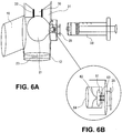
- FIG 6 is an illustration of an embodiment of a valve control mechanism for use with the port and valve assembly of Figures 3 and 4 . This figure demonstrates how the balloon 21 inflates to close off the flow of fluid from the catheter to the drainage bag by blocking flow from the opening 30 to the urinary drainage end of the port and valve assembly.
- the balloon may be inflated by other means such as a syringe.
- Figures 6A and 6B show one embodiment of the port and valve assemble in which the compliant balloon is inflated by a syringe 28. Air or fluid is introduced into the balloon by the syringe which attaches onto a luer locking connection 29, which has a valve 61 attached to a spring 62. When the syringe is attached it pushes prongs 63 on the surface of valve 61, depressing the valve and spring and opening a fluid connection between the syringe and balloon cavity 64. When the syringe is removed, the spring pushes the valve closed sealing the compartment and trapping the air or fluid within the balloon, keeping it inflated. In order to restart the flow of urine from the bladder to the urinary drainage bag, a syringe is simply re-attached to the luer locking port and the air or fluid is removed from the balloon.
- the air in the balloon slowly leaks out through a different air passage 26 from which it entered and through a block 27 with one or more holes, as described above.
- the valve control mechanism 16 in some embodiments may employ a lever instead of a balloon which pushes the valve shut.
- any aspect of an improved aseptic urinary drainage device and system may have components with different shapes or designs within different embodiments.
- spring types, housing shape, valve diameter and compositions may vary in design from one embodiment to another, but not overall function.
- the catheter connection port may be the drainage end of a urinary catheter.
- the urine exit port may be an intrinsic part of the urine collection device, and in some embodiments the port and valve assembly may be separate from the urine collection device.
Landscapes
- Health & Medical Sciences (AREA)
- Life Sciences & Earth Sciences (AREA)
- Molecular Biology (AREA)
- Surgery (AREA)
- Engineering & Computer Science (AREA)
- Biomedical Technology (AREA)
- Heart & Thoracic Surgery (AREA)
- Medical Informatics (AREA)
- Hematology (AREA)
- Pathology (AREA)
- Animal Behavior & Ethology (AREA)
- General Health & Medical Sciences (AREA)
- Public Health (AREA)
- Veterinary Medicine (AREA)
- External Artificial Organs (AREA)
- Infusion, Injection, And Reservoir Apparatuses (AREA)
Claims (14)
- Système de raccordement de cathéter urinaire (10) comprenant :un boîtier ;un orifice de raccord de cathéter (7) soutenu par le boîtier et conçu pour s'attacher à un cathéter urinaire ;un orifice de sortie d'urine (8) soutenu par le boîtier et conçu pour être raccordé à un dispositif de recueil d'urine ;un orifice d'irrigation (12) soutenu par le boîtier et conçu pour recevoir une seringue d'irrigation (13) ;un canal dans le boîtier reliant de manière fluidique l'orifice de raccord de cathéter, l'orifice de sortie d'urine et l'orifice d'irrigation ; etune valve (15, 30) soutenue par le boîtier et conçue pour coopérer avec la seringue d'irrigation pour bloquer l'écoulement de fluide et d'air vers l'orifice de sortie d'urine lorsque la seringue d'irrigation est insérée et permettre l'écoulement de fluide et d'air vers l'orifice de sortie d'urine lorsque la seringue d'irrigation est retirée ;caractérisé en ce que le système comprend en outre une membrane flexible (9) recouvrant l'orifice d'irrigation (12), la membrane flexible présentant une ouverture auto-étanche (23) conçue pour permettre à un embout de la seringue d'irrigation de traverser celle-ci, la membrane flexible (9) étant disposée à une distance d'une extrémité distale de la valve (15, 30) de manière que l'embout de la seringue d'irrigation peut traverser l'ouverture auto-étanche (23) vers l'extrémité distale de la valve lorsque la seringue d'irrigation (13) est insérée dans l'orifice d'irrigation (12).
- Système selon la revendication 1, dans lequel l'orifice d'irrigation comprend une surface extérieure qui est plate et peut être complètement exposée au frottement appliqué avec un agent désinfectant médical de manière que l'orifice d'irrigation peut être entièrement désinfecté.
- Appareil selon la revendication 1, dans lequel la valve (15) présente une première position dans laquelle le dispositif de recueil d'urine est en communication fluidique avec l'orifice de raccord de cathéter (7) et une deuxième position dans laquelle le dispositif de recueil d'urine n'est pas en communication fluidique avec l'orifice de raccord de cathéter (7).
- Système selon la revendication 3, dans lequel la valve (15) est déviée vers la première position.
- Système selon la revendication 4, dans lequel la valve (15) comprend un ressort (17).
- Système selon la revendication 4, dans lequel la valve (15) est conçue pour être déplacée de la première position vers la deuxième position par un embout de seringue inséré dans l'orifice d'irrigation (12).
- Système selon la revendication 1, dans lequel la valve (30) comprend un épaississement dans la paroi du boîtier, ledit épaississement réduisant le diamètre du canal et étant conçu pour être proche de la taille de l'embout d'une seringue d'irrigation (13) et pour s'accoupler de manière serrée avec la seringue d'irrigation, la seringue d'irrigation (13) étant insérée dans la valve (30), le dispositif de recueil d'urine n'étant pas en communication fluidique avec l'orifice de raccord de cathéter (7), et lorsque la seringue (13) n'est pas insérée dans l'ouverture de la valve (31), le dispositif de recueil d'urine est en communication fluidique avec l'orifice de raccord de cathéter (7).
- Système selon la revendication 1, dans lequel la valve (30) comprend un siège de valve conçu pour s'accoupler avec une surface extérieure de la seringue d'irrigation (13) pour bloquer l'écoulement de fluide et d'air vers l'orifice de sortie d'urine (8) lorsque la seringue d'irrigation (13) est insérée et permettre l'écoulement de fluide et d'air vers l'orifice de sortie d'urine (8) lorsque la seringue d'irrigation (130) est retirée.
- Système selon la revendication 1, dans lequel la valve (15) présente une première position dans laquelle le dispositif de recueil d'urine est en communication fluidique avec l'orifice de raccord de cathéter (7) et une deuxième position dans laquelle le dispositif de recueil d'urine n'est pas en communication fluidique avec l'orifice de raccord de cathéter (7), le système comprenant en outre un mécanisme de commande de valve (16) conçu pour déplacer la valve de la première position à la deuxième position sans insérer un dispositif dans l'orifice d'irrigation (12).
- Système selon la revendication 9, dans lequel le mécanisme de commande de valve (16) est conçu pour permettre automatiquement à la valve (15) de se déplacer de la deuxième position à la première position après une période de temps sans intervention humaine.
- Système selon la revendication 9, dans lequel le mécanisme de commande de valve (16) comprend un ballonnet souple (21).
- Système selon la revendication 1, dans lequel l'orifice d'irrigation (12) est raccordé au canal entre l'orifice de raccord de cathéter (7) et l'orifice de sortie d'urine (8).
- Système selon la revendication 1, comprenant en outre un mécanisme de commande de valve (16) comprenant un ballonnet souple (21) conçu pour être gonflé pour fermer la valve (15) lorsque la seringue d'irrigation (13) n'est pas insérée.
- Système selon la revendication 13, dans lequel le mécanisme de commande de valve (16) comprend en outre un orifice pour seringue (29) conçu pour permettre le gonflage du ballonnet (21) par une seringue (28).
Applications Claiming Priority (2)
| Application Number | Priority Date | Filing Date | Title |
|---|---|---|---|
| US201161464705P | 2011-03-08 | 2011-03-08 | |
| PCT/US2012/028021 WO2012148575A2 (fr) | 2011-03-08 | 2012-03-07 | Procédés et dispositifs pour l'irrigation aseptique, l'échantillonnage d'urine et la régulation de l'écoulement d'urine d'une vessie cathétérisée |
Publications (3)
| Publication Number | Publication Date |
|---|---|
| EP2683435A2 EP2683435A2 (fr) | 2014-01-15 |
| EP2683435A4 EP2683435A4 (fr) | 2014-10-29 |
| EP2683435B1 true EP2683435B1 (fr) | 2018-05-09 |
Family
ID=46796375
Family Applications (1)
| Application Number | Title | Priority Date | Filing Date |
|---|---|---|---|
| EP12776605.3A Not-in-force EP2683435B1 (fr) | 2011-03-08 | 2012-03-07 | Dispositifs pour l'irrigation aseptique, l'échantillonnage d'urine et la régulation de l'écoulement d'urine d'une vessie cathétérisée |
Country Status (5)
| Country | Link |
|---|---|
| US (1) | US9060752B2 (fr) |
| EP (1) | EP2683435B1 (fr) |
| JP (1) | JP2014511252A (fr) |
| DK (1) | DK2683435T3 (fr) |
| WO (1) | WO2012148575A2 (fr) |
Families Citing this family (9)
| Publication number | Priority date | Publication date | Assignee | Title |
|---|---|---|---|---|
| US10076635B2 (en) | 2011-03-08 | 2018-09-18 | Hospi Corporation | Methods and devices for aseptic irrigation, urine sampling, and flow control of urine from a catheterized bladder |
| WO2016133747A1 (fr) | 2015-02-20 | 2016-08-25 | Portela Soni Medical Llc | Cathéter urinaire amélioré, kit et procédé |
| WO2017002050A2 (fr) * | 2015-06-30 | 2017-01-05 | Jayaratne Anuruddika | Dispositif à tube de cathéter et vessie publique externe à système de suspension |
| CN105213083B (zh) * | 2015-11-11 | 2018-06-29 | 温岭市中医院 | 一种失禁病人用的尿裤结构 |
| SE540611C2 (en) | 2016-08-17 | 2018-10-02 | Meduly Ab C/O Inkubatorn I Boraas Ab | A urinary catheter connector for irrigation of a catheterized bladder. |
| EP3518840B1 (fr) | 2016-09-29 | 2024-06-12 | Dignity Health | Système de cathéter destiné à drainer un liquide corporel à partir d'une source de liquide dans un corps |
| JP6535126B2 (ja) * | 2018-06-26 | 2019-06-26 | 独立行政法人国立病院機構 | 間欠自己導尿カテーテル |
| CN110200662B (zh) * | 2019-06-25 | 2022-10-11 | 刘力君 | 一种肾内科导尿取样装置 |
| US20240188943A1 (en) * | 2021-04-15 | 2024-06-13 | Coloplast A/S | A Collector and an Intermittent Urinary Catheter Assembly comprising a Collector |
Family Cites Families (29)
| Publication number | Priority date | Publication date | Assignee | Title |
|---|---|---|---|---|
| US1234582A (en) | 1916-12-14 | 1917-07-24 | Barclay T Trueblood | Hypodermic syringe. |
| US3513849A (en) * | 1968-05-14 | 1970-05-26 | Bard Inc C R | Irrigation adapter for closed urinary drainage system |
| US3699964A (en) * | 1970-07-02 | 1972-10-24 | Bard Inc C R | Closed urinary drainage and irrigation system |
| US3707972A (en) * | 1971-07-28 | 1973-01-02 | Kendall & Co | Irrigation connector with shut-off valve |
| US3835835A (en) | 1972-11-07 | 1974-09-17 | Richardson Merrell Inc | Two compartment locking sampling syringe |
| US3965910A (en) | 1975-04-28 | 1976-06-29 | Walpak Company | Urinary irrigation valve |
| US4476866A (en) | 1982-08-06 | 1984-10-16 | Thomas J. Fogarty | Combined large and small bore syringe |
| US4685910A (en) | 1986-01-21 | 1987-08-11 | Abbott Laboratories | Apparatus and method for delivering secondary fluids to a patient using an intravenous administration set feeding a primary fluid |
| US4723943A (en) | 1986-12-31 | 1988-02-09 | Montana Deaconess Medical Center | Sheathed syringe |
| RU1806770C (ru) | 1991-04-05 | 1993-04-07 | В.А.Борисенко | Катетер В.А.Борисенко дл обтурационной эзофагорентгенографии и эзофаготерапии |
| JP3242656B2 (ja) | 1992-06-02 | 2001-12-25 | プロフィフォルム、アクチエンゲゼルシャフト | 自動閉鎖形カテーテル弁 |
| RU2116802C1 (ru) | 1994-08-09 | 1998-08-10 | Московский областной научно-исследовательский клинический институт | Устройство для промывания брюшной полости |
| US5810768A (en) * | 1995-06-07 | 1998-09-22 | Icu Medical, Inc. | Medical connector |
| US6245048B1 (en) * | 1996-12-16 | 2001-06-12 | Icu Medical, Inc. | Medical valve with positive flow characteristics |
| US5957898A (en) * | 1997-05-20 | 1999-09-28 | Baxter International Inc. | Needleless connector |
| US6165168A (en) | 1997-09-02 | 2000-12-26 | Russo; Ronald D. | Closed system adapter for catheters |
| US6183413B1 (en) | 1998-12-09 | 2001-02-06 | Hk Medical Technologies Incorporated | Valve for bladder control device |
| WO2001051117A1 (fr) * | 2000-01-11 | 2001-07-19 | Blatter Duane D | Ballonnets d'occlusion vasculaire, dispositifs et systemes associes utilises pour acceder aux vaisseaux |
| US6793651B1 (en) | 2000-02-23 | 2004-09-21 | Icu Medical, Inc. | Urinary catheter system with a releasable connector |
| US8353895B2 (en) * | 2002-04-16 | 2013-01-15 | Ronald D Russo | Closed system irrigation connector for urinary catheters |
| US20030195478A1 (en) * | 2002-04-16 | 2003-10-16 | Russo Ronald D. | Closed system irrigation connector for urinary catheters |
| US7056308B2 (en) * | 2002-10-04 | 2006-06-06 | Dsu Medical Corporation | Medical device with elastomeric penetrable wall and inner seal |
| US6913244B1 (en) | 2003-05-02 | 2005-07-05 | Gordon Edgar Atkinson | Urinary slide valve |
| US7056301B2 (en) | 2003-09-05 | 2006-06-06 | Jung-O Liu | Syringe |
| US7458957B2 (en) | 2005-03-17 | 2008-12-02 | William J. Dwyer | Universal valve for Foley type urinary catheter |
| US8529517B2 (en) | 2005-05-02 | 2013-09-10 | Shi Zi Technology, Ltd. | Autoflush syringe |
| US8075533B2 (en) | 2005-05-02 | 2011-12-13 | Preventiv, Inc. | Autoflush syringe |
| CA2668792C (fr) | 2008-06-30 | 2017-08-01 | Tyco Healthcare Group Lp | Vanne comprenant un element soluble |
| US20120277664A1 (en) | 2011-04-28 | 2012-11-01 | Macy Jr Bradford | Method and device for the irrigation and drainage of wounds, tubes, and body orifices |
-
2012
- 2012-03-07 US US13/414,205 patent/US9060752B2/en not_active Expired - Fee Related
- 2012-03-07 WO PCT/US2012/028021 patent/WO2012148575A2/fr active Application Filing
- 2012-03-07 JP JP2013557821A patent/JP2014511252A/ja active Pending
- 2012-03-07 EP EP12776605.3A patent/EP2683435B1/fr not_active Not-in-force
- 2012-03-07 DK DK12776605.3T patent/DK2683435T3/en active
Non-Patent Citations (1)
| Title |
|---|
| None * |
Also Published As
| Publication number | Publication date |
|---|---|
| DK2683435T3 (en) | 2018-07-23 |
| US9060752B2 (en) | 2015-06-23 |
| US20120232503A1 (en) | 2012-09-13 |
| EP2683435A4 (fr) | 2014-10-29 |
| WO2012148575A3 (fr) | 2013-01-17 |
| WO2012148575A2 (fr) | 2012-11-01 |
| JP2014511252A (ja) | 2014-05-15 |
| EP2683435A2 (fr) | 2014-01-15 |
Similar Documents
| Publication | Publication Date | Title |
|---|---|---|
| US20190015626A1 (en) | Methods and devices for aseptic irrigation, urine sampling, and flow control of urine from a catheterized bladder | |
| EP2683435B1 (fr) | Dispositifs pour l'irrigation aseptique, l'échantillonnage d'urine et la régulation de l'écoulement d'urine d'une vessie cathétérisée | |
| EP1645304B1 (fr) | Vanne magnétique pour cathéter | |
| CN108136153B (zh) | 改进的导尿管、成套工具及方法 | |
| US10188827B2 (en) | Distal closing catheters and methods for same | |
| US20130245496A1 (en) | Urinary catheter anti-reflux and pathogen block device | |
| US20210205589A1 (en) | Catheter and click connector | |
| US20170224977A1 (en) | Urinary catheter irrigation device and method of irrigating a urinary catheter | |
| JP2012509110A (ja) | 排泄物管理システム | |
| WO2004033025A1 (fr) | Ensemble catheter et vanne sans aiguille | |
| EP3041560A1 (fr) | Ensemble cathéter avec fixation facile pour tube ou poche | |
| US20150196730A1 (en) | Indwelling urinary catheter | |
| CA3142591C (fr) | Catheter urinaire a fil-guide | |
| WO1999043971A1 (fr) | Valve de rinçage pour rinçage unidirectionnel de catheters de drainage | |
| CN221845597U (en) | Visual antibacterial drainage catheter | |
| CN219208309U (zh) | 一种自冲洗和疏通的引流装置 | |
| US20240342445A1 (en) | Catheter and click connector | |
| CN211327694U (zh) | 一种泌尿外科用导尿装置 | |
| WO2024151250A1 (fr) | Poche de drainage avec chambre de dosage sous vide | |
| KR20230144241A (ko) | 확장형 음압 배액장치 및 유체 흐름 경로를 제공하는 의료기구 연결체 |
Legal Events
| Date | Code | Title | Description |
|---|---|---|---|
| PUAI | Public reference made under article 153(3) epc to a published international application that has entered the european phase |
Free format text: ORIGINAL CODE: 0009012 |
|
| 17P | Request for examination filed |
Effective date: 20131003 |
|
| AK | Designated contracting states |
Kind code of ref document: A2 Designated state(s): AL AT BE BG CH CY CZ DE DK EE ES FI FR GB GR HR HU IE IS IT LI LT LU LV MC MK MT NL NO PL PT RO RS SE SI SK SM TR |
|
| DAX | Request for extension of the european patent (deleted) | ||
| A4 | Supplementary search report drawn up and despatched |
Effective date: 20140926 |
|
| RIC1 | Information provided on ipc code assigned before grant |
Ipc: A61M 25/00 20060101AFI20140922BHEP |
|
| GRAP | Despatch of communication of intention to grant a patent |
Free format text: ORIGINAL CODE: EPIDOSNIGR1 |
|
| STAA | Information on the status of an ep patent application or granted ep patent |
Free format text: STATUS: GRANT OF PATENT IS INTENDED |
|
| RIC1 | Information provided on ipc code assigned before grant |
Ipc: A61M 25/00 20060101AFI20170926BHEP Ipc: A61B 10/00 20060101ALI20170926BHEP |
|
| INTG | Intention to grant announced |
Effective date: 20171026 |
|
| GRAS | Grant fee paid |
Free format text: ORIGINAL CODE: EPIDOSNIGR3 |
|
| GRAA | (expected) grant |
Free format text: ORIGINAL CODE: 0009210 |
|
| STAA | Information on the status of an ep patent application or granted ep patent |
Free format text: STATUS: THE PATENT HAS BEEN GRANTED |
|
| AK | Designated contracting states |
Kind code of ref document: B1 Designated state(s): AL AT BE BG CH CY CZ DE DK EE ES FI FR GB GR HR HU IE IS IT LI LT LU LV MC MK MT NL NO PL PT RO RS SE SI SK SM TR |
|
| REG | Reference to a national code |
Ref country code: GB Ref legal event code: FG4D |
|
| REG | Reference to a national code |
Ref country code: CH Ref legal event code: EP Ref country code: AT Ref legal event code: REF Ref document number: 997007 Country of ref document: AT Kind code of ref document: T Effective date: 20180515 |
|
| REG | Reference to a national code |
Ref country code: IE Ref legal event code: FG4D |
|
| REG | Reference to a national code |
Ref country code: DE Ref legal event code: R096 Ref document number: 602012046208 Country of ref document: DE |
|
| REG | Reference to a national code |
Ref country code: DK Ref legal event code: T3 Effective date: 20180716 |
|
| REG | Reference to a national code |
Ref country code: NL Ref legal event code: MP Effective date: 20180509 |
|
| REG | Reference to a national code |
Ref country code: LT Ref legal event code: MG4D |
|
| PG25 | Lapsed in a contracting state [announced via postgrant information from national office to epo] |
Ref country code: ES Free format text: LAPSE BECAUSE OF FAILURE TO SUBMIT A TRANSLATION OF THE DESCRIPTION OR TO PAY THE FEE WITHIN THE PRESCRIBED TIME-LIMIT Effective date: 20180509 Ref country code: LT Free format text: LAPSE BECAUSE OF FAILURE TO SUBMIT A TRANSLATION OF THE DESCRIPTION OR TO PAY THE FEE WITHIN THE PRESCRIBED TIME-LIMIT Effective date: 20180509 Ref country code: BG Free format text: LAPSE BECAUSE OF FAILURE TO SUBMIT A TRANSLATION OF THE DESCRIPTION OR TO PAY THE FEE WITHIN THE PRESCRIBED TIME-LIMIT Effective date: 20180809 Ref country code: NO Free format text: LAPSE BECAUSE OF FAILURE TO SUBMIT A TRANSLATION OF THE DESCRIPTION OR TO PAY THE FEE WITHIN THE PRESCRIBED TIME-LIMIT Effective date: 20180809 Ref country code: SE Free format text: LAPSE BECAUSE OF FAILURE TO SUBMIT A TRANSLATION OF THE DESCRIPTION OR TO PAY THE FEE WITHIN THE PRESCRIBED TIME-LIMIT Effective date: 20180509 Ref country code: FI Free format text: LAPSE BECAUSE OF FAILURE TO SUBMIT A TRANSLATION OF THE DESCRIPTION OR TO PAY THE FEE WITHIN THE PRESCRIBED TIME-LIMIT Effective date: 20180509 |
|
| PG25 | Lapsed in a contracting state [announced via postgrant information from national office to epo] |
Ref country code: GR Free format text: LAPSE BECAUSE OF FAILURE TO SUBMIT A TRANSLATION OF THE DESCRIPTION OR TO PAY THE FEE WITHIN THE PRESCRIBED TIME-LIMIT Effective date: 20180810 Ref country code: RS Free format text: LAPSE BECAUSE OF FAILURE TO SUBMIT A TRANSLATION OF THE DESCRIPTION OR TO PAY THE FEE WITHIN THE PRESCRIBED TIME-LIMIT Effective date: 20180509 Ref country code: NL Free format text: LAPSE BECAUSE OF FAILURE TO SUBMIT A TRANSLATION OF THE DESCRIPTION OR TO PAY THE FEE WITHIN THE PRESCRIBED TIME-LIMIT Effective date: 20180509 Ref country code: LV Free format text: LAPSE BECAUSE OF FAILURE TO SUBMIT A TRANSLATION OF THE DESCRIPTION OR TO PAY THE FEE WITHIN THE PRESCRIBED TIME-LIMIT Effective date: 20180509 Ref country code: HR Free format text: LAPSE BECAUSE OF FAILURE TO SUBMIT A TRANSLATION OF THE DESCRIPTION OR TO PAY THE FEE WITHIN THE PRESCRIBED TIME-LIMIT Effective date: 20180509 |
|
| REG | Reference to a national code |
Ref country code: AT Ref legal event code: MK05 Ref document number: 997007 Country of ref document: AT Kind code of ref document: T Effective date: 20180509 |
|
| PG25 | Lapsed in a contracting state [announced via postgrant information from national office to epo] |
Ref country code: CZ Free format text: LAPSE BECAUSE OF FAILURE TO SUBMIT A TRANSLATION OF THE DESCRIPTION OR TO PAY THE FEE WITHIN THE PRESCRIBED TIME-LIMIT Effective date: 20180509 Ref country code: SK Free format text: LAPSE BECAUSE OF FAILURE TO SUBMIT A TRANSLATION OF THE DESCRIPTION OR TO PAY THE FEE WITHIN THE PRESCRIBED TIME-LIMIT Effective date: 20180509 Ref country code: EE Free format text: LAPSE BECAUSE OF FAILURE TO SUBMIT A TRANSLATION OF THE DESCRIPTION OR TO PAY THE FEE WITHIN THE PRESCRIBED TIME-LIMIT Effective date: 20180509 Ref country code: PL Free format text: LAPSE BECAUSE OF FAILURE TO SUBMIT A TRANSLATION OF THE DESCRIPTION OR TO PAY THE FEE WITHIN THE PRESCRIBED TIME-LIMIT Effective date: 20180509 Ref country code: RO Free format text: LAPSE BECAUSE OF FAILURE TO SUBMIT A TRANSLATION OF THE DESCRIPTION OR TO PAY THE FEE WITHIN THE PRESCRIBED TIME-LIMIT Effective date: 20180509 Ref country code: AT Free format text: LAPSE BECAUSE OF FAILURE TO SUBMIT A TRANSLATION OF THE DESCRIPTION OR TO PAY THE FEE WITHIN THE PRESCRIBED TIME-LIMIT Effective date: 20180509 |
|
| REG | Reference to a national code |
Ref country code: DE Ref legal event code: R097 Ref document number: 602012046208 Country of ref document: DE |
|
| PG25 | Lapsed in a contracting state [announced via postgrant information from national office to epo] |
Ref country code: SM Free format text: LAPSE BECAUSE OF FAILURE TO SUBMIT A TRANSLATION OF THE DESCRIPTION OR TO PAY THE FEE WITHIN THE PRESCRIBED TIME-LIMIT Effective date: 20180509 Ref country code: IT Free format text: LAPSE BECAUSE OF FAILURE TO SUBMIT A TRANSLATION OF THE DESCRIPTION OR TO PAY THE FEE WITHIN THE PRESCRIBED TIME-LIMIT Effective date: 20180509 |
|
| PLBE | No opposition filed within time limit |
Free format text: ORIGINAL CODE: 0009261 |
|
| STAA | Information on the status of an ep patent application or granted ep patent |
Free format text: STATUS: NO OPPOSITION FILED WITHIN TIME LIMIT |
|
| 26N | No opposition filed |
Effective date: 20190212 |
|
| PG25 | Lapsed in a contracting state [announced via postgrant information from national office to epo] |
Ref country code: SI Free format text: LAPSE BECAUSE OF FAILURE TO SUBMIT A TRANSLATION OF THE DESCRIPTION OR TO PAY THE FEE WITHIN THE PRESCRIBED TIME-LIMIT Effective date: 20180509 |
|
| PG25 | Lapsed in a contracting state [announced via postgrant information from national office to epo] |
Ref country code: MC Free format text: LAPSE BECAUSE OF FAILURE TO SUBMIT A TRANSLATION OF THE DESCRIPTION OR TO PAY THE FEE WITHIN THE PRESCRIBED TIME-LIMIT Effective date: 20180509 |
|
| REG | Reference to a national code |
Ref country code: CH Ref legal event code: PL |
|
| PG25 | Lapsed in a contracting state [announced via postgrant information from national office to epo] |
Ref country code: LU Free format text: LAPSE BECAUSE OF NON-PAYMENT OF DUE FEES Effective date: 20190307 Ref country code: AL Free format text: LAPSE BECAUSE OF FAILURE TO SUBMIT A TRANSLATION OF THE DESCRIPTION OR TO PAY THE FEE WITHIN THE PRESCRIBED TIME-LIMIT Effective date: 20180509 |
|
| REG | Reference to a national code |
Ref country code: BE Ref legal event code: MM Effective date: 20190331 |
|
| PG25 | Lapsed in a contracting state [announced via postgrant information from national office to epo] |
Ref country code: CH Free format text: LAPSE BECAUSE OF NON-PAYMENT OF DUE FEES Effective date: 20190331 Ref country code: IE Free format text: LAPSE BECAUSE OF NON-PAYMENT OF DUE FEES Effective date: 20190307 Ref country code: LI Free format text: LAPSE BECAUSE OF NON-PAYMENT OF DUE FEES Effective date: 20190331 |
|
| PG25 | Lapsed in a contracting state [announced via postgrant information from national office to epo] |
Ref country code: BE Free format text: LAPSE BECAUSE OF NON-PAYMENT OF DUE FEES Effective date: 20190331 |
|
| PG25 | Lapsed in a contracting state [announced via postgrant information from national office to epo] |
Ref country code: TR Free format text: LAPSE BECAUSE OF FAILURE TO SUBMIT A TRANSLATION OF THE DESCRIPTION OR TO PAY THE FEE WITHIN THE PRESCRIBED TIME-LIMIT Effective date: 20180509 |
|
| PG25 | Lapsed in a contracting state [announced via postgrant information from national office to epo] |
Ref country code: MT Free format text: LAPSE BECAUSE OF NON-PAYMENT OF DUE FEES Effective date: 20190307 Ref country code: PT Free format text: LAPSE BECAUSE OF FAILURE TO SUBMIT A TRANSLATION OF THE DESCRIPTION OR TO PAY THE FEE WITHIN THE PRESCRIBED TIME-LIMIT Effective date: 20180910 |
|
| PG25 | Lapsed in a contracting state [announced via postgrant information from national office to epo] |
Ref country code: CY Free format text: LAPSE BECAUSE OF FAILURE TO SUBMIT A TRANSLATION OF THE DESCRIPTION OR TO PAY THE FEE WITHIN THE PRESCRIBED TIME-LIMIT Effective date: 20180509 |
|
| PG25 | Lapsed in a contracting state [announced via postgrant information from national office to epo] |
Ref country code: IS Free format text: LAPSE BECAUSE OF FAILURE TO SUBMIT A TRANSLATION OF THE DESCRIPTION OR TO PAY THE FEE WITHIN THE PRESCRIBED TIME-LIMIT Effective date: 20180909 |
|
| PG25 | Lapsed in a contracting state [announced via postgrant information from national office to epo] |
Ref country code: HU Free format text: LAPSE BECAUSE OF FAILURE TO SUBMIT A TRANSLATION OF THE DESCRIPTION OR TO PAY THE FEE WITHIN THE PRESCRIBED TIME-LIMIT; INVALID AB INITIO Effective date: 20120307 |
|
| PGFP | Annual fee paid to national office [announced via postgrant information from national office to epo] |
Ref country code: GB Payment date: 20220113 Year of fee payment: 11 Ref country code: DK Payment date: 20220309 Year of fee payment: 11 Ref country code: DE Payment date: 20220112 Year of fee payment: 11 |
|
| PGFP | Annual fee paid to national office [announced via postgrant information from national office to epo] |
Ref country code: FR Payment date: 20220118 Year of fee payment: 11 |
|
| PG25 | Lapsed in a contracting state [announced via postgrant information from national office to epo] |
Ref country code: MK Free format text: LAPSE BECAUSE OF FAILURE TO SUBMIT A TRANSLATION OF THE DESCRIPTION OR TO PAY THE FEE WITHIN THE PRESCRIBED TIME-LIMIT Effective date: 20180509 |
|
| REG | Reference to a national code |
Ref country code: DE Ref legal event code: R119 Ref document number: 602012046208 Country of ref document: DE |
|
| REG | Reference to a national code |
Ref country code: DK Ref legal event code: EBP Effective date: 20230331 |
|
| GBPC | Gb: european patent ceased through non-payment of renewal fee |
Effective date: 20230307 |
|
| PG25 | Lapsed in a contracting state [announced via postgrant information from national office to epo] |
Ref country code: GB Free format text: LAPSE BECAUSE OF NON-PAYMENT OF DUE FEES Effective date: 20230307 |
|
| PG25 | Lapsed in a contracting state [announced via postgrant information from national office to epo] |
Ref country code: GB Free format text: LAPSE BECAUSE OF NON-PAYMENT OF DUE FEES Effective date: 20230307 Ref country code: FR Free format text: LAPSE BECAUSE OF NON-PAYMENT OF DUE FEES Effective date: 20230331 Ref country code: DE Free format text: LAPSE BECAUSE OF NON-PAYMENT OF DUE FEES Effective date: 20231003 |
|
| PG25 | Lapsed in a contracting state [announced via postgrant information from national office to epo] |
Ref country code: DK Free format text: LAPSE BECAUSE OF NON-PAYMENT OF DUE FEES Effective date: 20230331 |