EP2683229A2 - Electronic component box for vehicle - Google Patents
Electronic component box for vehicle Download PDFInfo
- Publication number
- EP2683229A2 EP2683229A2 EP13172291.0A EP13172291A EP2683229A2 EP 2683229 A2 EP2683229 A2 EP 2683229A2 EP 13172291 A EP13172291 A EP 13172291A EP 2683229 A2 EP2683229 A2 EP 2683229A2
- Authority
- EP
- European Patent Office
- Prior art keywords
- electronic component
- component box
- housing
- box according
- cover
- Prior art date
- Legal status (The legal status is an assumption and is not a legal conclusion. Google has not performed a legal analysis and makes no representation as to the accuracy of the status listed.)
- Withdrawn
Links
- 239000000463 material Substances 0.000 claims abstract description 13
- 238000001746 injection moulding Methods 0.000 claims abstract description 8
- 238000001816 cooling Methods 0.000 claims description 40
- PXHVJJICTQNCMI-UHFFFAOYSA-N Nickel Chemical compound [Ni] PXHVJJICTQNCMI-UHFFFAOYSA-N 0.000 claims description 20
- 239000011651 chromium Substances 0.000 claims description 16
- 229910052804 chromium Inorganic materials 0.000 claims description 9
- 239000010949 copper Substances 0.000 claims description 9
- 229910052759 nickel Inorganic materials 0.000 claims description 8
- VYZAMTAEIAYCRO-UHFFFAOYSA-N Chromium Chemical compound [Cr] VYZAMTAEIAYCRO-UHFFFAOYSA-N 0.000 claims description 7
- XEEYBQQBJWHFJM-UHFFFAOYSA-N Iron Chemical compound [Fe] XEEYBQQBJWHFJM-UHFFFAOYSA-N 0.000 claims description 6
- 229910052782 aluminium Inorganic materials 0.000 claims description 5
- XAGFODPZIPBFFR-UHFFFAOYSA-N aluminium Chemical compound [Al] XAGFODPZIPBFFR-UHFFFAOYSA-N 0.000 claims description 5
- 229910052802 copper Inorganic materials 0.000 claims description 5
- RYGMFSIKBFXOCR-UHFFFAOYSA-N Copper Chemical compound [Cu] RYGMFSIKBFXOCR-UHFFFAOYSA-N 0.000 claims description 4
- 229910052742 iron Inorganic materials 0.000 claims description 3
- 229910052751 metal Inorganic materials 0.000 claims description 3
- 239000002184 metal Substances 0.000 claims description 3
- 239000002826 coolant Substances 0.000 description 18
- 230000007423 decrease Effects 0.000 description 4
- 229910000831 Steel Inorganic materials 0.000 description 3
- 238000000034 method Methods 0.000 description 3
- 238000012986 modification Methods 0.000 description 3
- 230000004048 modification Effects 0.000 description 3
- 238000007747 plating Methods 0.000 description 3
- 239000010959 steel Substances 0.000 description 3
- XLYOFNOQVPJJNP-UHFFFAOYSA-N water Substances O XLYOFNOQVPJJNP-UHFFFAOYSA-N 0.000 description 3
- 150000001875 compounds Chemical class 0.000 description 2
- 230000005611 electricity Effects 0.000 description 2
- 230000017525 heat dissipation Effects 0.000 description 2
- 238000007789 sealing Methods 0.000 description 2
- OKBJVIVEFXPEOU-UHFFFAOYSA-N 1,2,3-trichloro-4-(2,3,6-trichlorophenyl)benzene Chemical compound ClC1=C(Cl)C(Cl)=CC=C1C1=C(Cl)C=CC(Cl)=C1Cl OKBJVIVEFXPEOU-UHFFFAOYSA-N 0.000 description 1
- 238000005260 corrosion Methods 0.000 description 1
- 230000007797 corrosion Effects 0.000 description 1
- 230000000694 effects Effects 0.000 description 1
- 238000005265 energy consumption Methods 0.000 description 1
- 238000005516 engineering process Methods 0.000 description 1
- 239000007769 metal material Substances 0.000 description 1
- 239000000088 plastic resin Substances 0.000 description 1
- 239000000126 substance Substances 0.000 description 1
Images


Classifications
-
- H—ELECTRICITY
- H05—ELECTRIC TECHNIQUES NOT OTHERWISE PROVIDED FOR
- H05K—PRINTED CIRCUITS; CASINGS OR CONSTRUCTIONAL DETAILS OF ELECTRIC APPARATUS; MANUFACTURE OF ASSEMBLAGES OF ELECTRICAL COMPONENTS
- H05K5/00—Casings, cabinets or drawers for electric apparatus
- H05K5/02—Details
- H05K5/0209—Thermal insulation, e.g. for fire protection or for fire containment or for high temperature environments
-
- H—ELECTRICITY
- H05—ELECTRIC TECHNIQUES NOT OTHERWISE PROVIDED FOR
- H05K—PRINTED CIRCUITS; CASINGS OR CONSTRUCTIONAL DETAILS OF ELECTRIC APPARATUS; MANUFACTURE OF ASSEMBLAGES OF ELECTRICAL COMPONENTS
- H05K7/00—Constructional details common to different types of electric apparatus
- H05K7/20—Modifications to facilitate cooling, ventilating, or heating
- H05K7/2039—Modifications to facilitate cooling, ventilating, or heating characterised by the heat transfer by conduction from the heat generating element to a dissipating body
- H05K7/20436—Inner thermal coupling elements in heat dissipating housings, e.g. protrusions or depressions integrally formed in the housing
- H05K7/20445—Inner thermal coupling elements in heat dissipating housings, e.g. protrusions or depressions integrally formed in the housing the coupling element being an additional piece, e.g. thermal standoff
-
- B—PERFORMING OPERATIONS; TRANSPORTING
- B60—VEHICLES IN GENERAL
- B60R—VEHICLES, VEHICLE FITTINGS, OR VEHICLE PARTS, NOT OTHERWISE PROVIDED FOR
- B60R16/00—Electric or fluid circuits specially adapted for vehicles and not otherwise provided for; Arrangement of elements of electric or fluid circuits specially adapted for vehicles and not otherwise provided for
- B60R16/02—Electric or fluid circuits specially adapted for vehicles and not otherwise provided for; Arrangement of elements of electric or fluid circuits specially adapted for vehicles and not otherwise provided for electric constitutive elements
-
- H—ELECTRICITY
- H05—ELECTRIC TECHNIQUES NOT OTHERWISE PROVIDED FOR
- H05K—PRINTED CIRCUITS; CASINGS OR CONSTRUCTIONAL DETAILS OF ELECTRIC APPARATUS; MANUFACTURE OF ASSEMBLAGES OF ELECTRICAL COMPONENTS
- H05K9/00—Screening of apparatus or components against electric or magnetic fields
- H05K9/0073—Shielding materials
- H05K9/0081—Electromagnetic shielding materials, e.g. EMI, RFI shielding
- H05K9/0088—Electromagnetic shielding materials, e.g. EMI, RFI shielding comprising a plurality of shielding layers; combining different shielding material structure
Definitions
- the above-described electronic component box according to the related art adopts a water cooling type heat-dissipation method.
- a cooling passage through which coolant flows is defined in an outer bottom surface of the housing 3 by the bottom cover 2.
- the housing 3 and top cover 4 is formed of a steel plate cold commercial (SPCC) or aluminum steel to shield the electromagnetic waves to improve cooling efficient and EMS stability.
- SPCC steel plate cold commercial
- Fig. 3 is an exploded perspective view of the electronic component box.
- Fig. 5 is a cross-sectional view taken along line I-I' of Fig. 2 .
- Fig. 6 is a cross-sectional view taken along line II-II' of Fig. 2 .
- the electronic component box 10 includes a housing 11 defining an outer appearance thereof and having an opened top surface, a top cover 12 covering the opened top surface of the housing 11, a power-in connector 18 mounted on one surface of the housing 11, a power-out connecter 17 mounted on the other side of the housing 11, a signal connector 19, an electronic component set 13 accommodated within the housing 11, a base cover 14 on which the electronic component set 13 is seated, a first sealer 15 surrounded along contact surfaces of the top cover 12 and housing 11 to a waterproof function, and a second sealer 16 disposed between contact surfaces of the base cover 14 and the housing 11 to perform a waterproof function.
- An in-connector hole 114 in which the power-in connector 18 is mounted is defined in one side surface of the housing 11.
- an out-connector hole 116 in which the power-out connector 17 is mounted and a signal connector hole 115 in which the signal connector 19 is mounted are defined in the other side surface.
- the signal connector hole 115 may be defined in any one of one side surface and the other surface of the housing 11.
- a cooling passage 111 through which coolant flow is defined in a bottom surface of the housing 11 in a meander line shape.
- a coolant inflow port 112 into which coolant is introduced and a coolant discharge port 113 through which the coolant is discharged are disposed on a side surface of the housing 11.
- the coolant inflow port 112 and the coolant discharge port 113 may respectively communicate with an inlet and outlet of the cooling passage 111.
- the coolant introduced through the coolant inflow port 112 flows along the cooling passage 111 to cool the electronic component set 13 seated on a top surface of the base cover 14.
- the electronic components generating a relatively large amount of heat are disposed on a position close to the inlet of the cooling passage 111, and the electronic components generating a relatively small amount of heat are disposed on a position close to the outlet of the cooling passage 111 to improve heat exchange efficiency.
- the second sealer 16 is seated along an outer line of a top surface of the cooling passage 111, and the base cover 14 is seated on the second sealer 16 to prevent the coolant flowing along the cooling passage 111 from leaking toward the electronic component set 13.
- the first sealer 15 is seated along an edge of the top surface of the housing 111, and the top cover 12 is seated on the first sealer 15 to prevent water or foreign materials from being introduced into the housing 11 from the outside.
- the base cover 14 includes a cover body 141 and a plurality of cooling pins 142.
- the cover body 141 covers the cooling passage 111, and the plurality of cooling pins protrude from on back surface of the cover body 141, particularly, a portion of a back surface corresponding to an inner space of the cooling passage 111.
- the plurality of cooling pins 142 may be rounded along a profile of the cooling passage 111.
- the plurality of cooling pins 142 are spaced a predetermined distance from each other to heat-exchange with the coolant flowing along the cooing passage through heat conduction. That is, heat generated from the electronic component set 13 may be transferred into the coolant through the plurality of cooling pins 142.
- the electronic component set 13 may include a switching device 131 including an insulated gate bipolar mode transistor (IGBT) that switches a DC voltage to output a three-phase current voltage, a DC link cap 133 mounted on a side of the top surface of the base cover 14 to stabilize an input voltage and reduce noises of the switching device 131, and a power PCB 132.
- the electronic component set 13 may further include various electronic components that are not described herein.
- Each of the housing 11 and the top cover 12 may be formed of a light plastic material through plastic injection molding using a plastic resin.
- the housing 11 and the top cover 12 are formed of the plastic materials to decrease a weight thereof and improve price competiveness when compared to those formed of an existing iron or aluminum material.
- electromagnetic waves generated from the electronic component set 13 may not be effectively shield.
- the plated layer may have a maximum thickness in a case where copper (Cu) is plated to a thickness of about 20 ⁇ m, nickel (Ni) is plated to a thickness of about 15 ⁇ m, and chromium (Cr) is plated to a thickness of about 0.3 ⁇ m.
- the Cu, Ni, and Cr plated layers may be successively formed within a range of the maximum thickness and the minimum thickness.
- the cooling passage 11 may be defined in the inner bottom surface of the housing, and the top surface of the cooling passage 111 may be covered by the base cover 14.
- the opened top surface of the cooling passage 111 faces an upper side to prevent the coolant from leaking through the top surface of the cooling passage.
- cooling efficient may be reduced.
- the base cover 14 since the base cover 14 is seated on the top surface of the cooling passage, and the electronic component set 13 is seated on the top surface of the cover base 14, the heat-exchange efficiency may increase. That is, if heat discharged from the electronic component set 13 passes through only the base cover 14, since the heat may directly heat-exchange with the coolant, the heat-exchange efficient may significantly increase when compared to a double bottom structure according to the related art.
- the aluminum, the steel plate cold commercial (SPCC), or different kinds of metal plate which shields the electromagnetic waves and has high heat conductivity is applied as the material of the base cover 14, it is not necessary to perform a separate plating process onto the bottom portion of the housing 11 covered by the base cover 14. Thus, the plating processing costs may be reduced.
- the above-described the electronic component box according to the embodiments may have following effects.
- the electronic component box may decrease in self-weight.
- the electromagnet shielding function may be maintained or further improved.
- the cooling passage may be defined within the housing of the electronic component box to decrease the thickness of the electronic component box.
- the leakage of the coolant to the outside of the electronic component box may be prevented to reduce possibility of corrosion or electrical short-circuit of other components of the vehicle.
Landscapes
- Engineering & Computer Science (AREA)
- Microelectronics & Electronic Packaging (AREA)
- Physics & Mathematics (AREA)
- Electromagnetism (AREA)
- Thermal Sciences (AREA)
- Mechanical Engineering (AREA)
- Shielding Devices Or Components To Electric Or Magnetic Fields (AREA)
- Cooling Or The Like Of Electrical Apparatus (AREA)
- Casings For Electric Apparatus (AREA)
Abstract
Description
- The present application claims the benefits of priority to Korean Patent Application No.
10-2012-0073174 (filed on July 5, 2012 - The present disclosure relates to an electronic component box for vehicles.
- Recently, technologies with respect to electric vehicles driven by using electricity that is green energy are being rapidly developed. Most of electric vehicles include a motor generating torque, a battery supplying a power to the motor, an inverter controlling the number of revolution of the motor, a battery charger charging electricity into the battery, and a low voltage DC/DC converter for vehicles.
- The electronic components generate a large amount of heat and a lot of electromagnetic waves or noises that have an influence on operations of other electronic components during the operation thereof. To solve the above-described limitations, the electronic compounds are accommodated within an electronic compound box that has an air cooling type or water cooling type heat-dissipation structure and a shield function shielding EMI electromagnetic waves to satisfy electro magnetic compatibility (EMC).
-
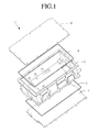
Fig. 1 is an exploded perspective view of an electronic component box for a vehicle according to a related art. - Referring to
Fig. 1 , an electronic component box 1 for a vehicle according to the related art includes abottom cover 2 having a cooling passage in a top surface thereof, ahousing 3 fixed to the top surface of thebottom cover 2 to accommodate all sorts of electronic components therein, atop cover 4 covering an opened top surface of the housing, anupper sealer 6 disposed between contact portions of thetop cover 4 and thehousing 3 to perform a sealing function, and alower sealer 5 disposed between contact portions of thebottom cover 2 and thehousing 3 to perform a sealing function. - The above-described electronic component box according to the related art adopts a water cooling type heat-dissipation method. Here, a cooling passage through which coolant flows is defined in an outer bottom surface of the
housing 3 by thebottom cover 2. - Also, the
housing 3 andtop cover 4 is formed of a steel plate cold commercial (SPCC) or aluminum steel to shield the electromagnetic waves to improve cooling efficient and EMS stability. - However, in the case of the electronic component box product according to the related art, since the housing shielding the electronic components are formed of metallic materials including iron or aluminum to increase a weight of the electronic component box and reduce fabricating price competitiveness. Furthermore, when the electronic component box is increased in weight, a self-weight of the vehicle is increased to increase an electrical energy consumption.
- Embodiments provide an electronic component box for a vehicle of which a self-weight decreases, but cooling efficiency and electromagnetic wave shielding function are maintained or improved.
- Embodiments also provide an electronic component box for a vehicle. The electronic component box including: a housing formed of a plastic material and manufactured through plastic injection molding, the housing having an opened top surface; a top cover formed of a plastic material and manufactured through the plastic injection molding, the top cover covering the opened top surface of the housing; a base cover seated on a bottom surface of the housing; an electronic component set seated on a top surface of the base cover; and a plated layer disposed on an inner circumferential surface of the housing and a back surface of the top cover to shield an electromagnetic wave.
- The details of one or more embodiments are set forth in the accompanying drawings and the description below. Other features will be apparent from the description and drawings, and from the claims.
-
Fig. 1 is an exploded perspective view of an electronic component box for a vehicle according to a related art. -
Fig. 2 is a perspective view illustrating an outer appearance of an electronic component box according to an embodiment. -
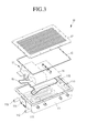
Fig. 3 is an exploded perspective view of the electronic component box. -
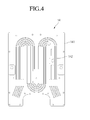
Fig. 4 is a bottom view of a base cover disposed within the electronic component box. -
Fig. 5 is a cross-sectional view taken along line I-I' ofFig. 2 . -
Fig. 6 is a cross-sectional view taken along line II-II' ofFig. 2 . - In the following detailed description of the preferred embodiments, reference is made to the accompanying drawings that form a part hereof, and in which is shown by way of illustration specific preferred embodiments in which the invention may be practiced. These embodiments are described in sufficient detail to enable those skilled in the art to practice the invention, and it is understood that other embodiments may be utilized and that logical structural, mechanical, electrical, and chemical changes may be made without departing from the spirit or scope of the invention. To avoid detail not necessary to enable those skilled in the art to practice the invention, the description may omit certain information known to those skilled in the art. The following detailed description is, therefore, not to be taken in a limiting sense, and the scope of the present invention is defined only by the appended claims.
- Hereinafter, an electronic component box for a vehicle, particularly, an electrical vehicle according to embodiments will be described in detail with reference to the accompanying drawings.
-
Fig. 2 is a perspective view of an outer appearance of an electronic component box according to an embodiment.Fig. 3 is an exploded perspective view of the electronic component box.Fig. 4 is a bottom view of a base cover disposed within the electronic component box.Fig. 5 is a cross-sectional view taken along line I-I' ofFig. 2 .Fig. 6 is a cross-sectional view taken along line II-II' ofFig. 2 . - Referring to
Figs. 2 to 6 , anelectronic component box 10 according to the embodiment may include an inverter, LDC, or an on-board charger (OBC). - In detail, the
electronic component box 10 includes ahousing 11 defining an outer appearance thereof and having an opened top surface, atop cover 12 covering the opened top surface of thehousing 11, a power-inconnector 18 mounted on one surface of thehousing 11, a power-outconnecter 17 mounted on the other side of thehousing 11, asignal connector 19, an electronic component set 13 accommodated within thehousing 11, abase cover 14 on which theelectronic component set 13 is seated, afirst sealer 15 surrounded along contact surfaces of thetop cover 12 and housing 11 to a waterproof function, and asecond sealer 16 disposed between contact surfaces of thebase cover 14 and thehousing 11 to perform a waterproof function. - An in-
connector hole 114 in which the power-inconnector 18 is mounted is defined in one side surface of thehousing 11. Also, an out-connector hole 116 in which the power-out connector 17 is mounted and asignal connector hole 115 in which thesignal connector 19 is mounted are defined in the other side surface. Thesignal connector hole 115 may be defined in any one of one side surface and the other surface of thehousing 11. - Also, a
cooling passage 111 through which coolant flow is defined in a bottom surface of thehousing 11 in a meander line shape. Also, acoolant inflow port 112 into which coolant is introduced and acoolant discharge port 113 through which the coolant is discharged are disposed on a side surface of thehousing 11. Thecoolant inflow port 112 and thecoolant discharge port 113 may respectively communicate with an inlet and outlet of thecooling passage 111. Thus, the coolant introduced through thecoolant inflow port 112 flows along thecooling passage 111 to cool the electronic component set 13 seated on a top surface of thebase cover 14. Here, the electronic components generating a relatively large amount of heat are disposed on a position close to the inlet of thecooling passage 111, and the electronic components generating a relatively small amount of heat are disposed on a position close to the outlet of thecooling passage 111 to improve heat exchange efficiency. - Also, the
second sealer 16 is seated along an outer line of a top surface of thecooling passage 111, and thebase cover 14 is seated on thesecond sealer 16 to prevent the coolant flowing along thecooling passage 111 from leaking toward the electronic component set 13. Thefirst sealer 15 is seated along an edge of the top surface of thehousing 111, and thetop cover 12 is seated on thefirst sealer 15 to prevent water or foreign materials from being introduced into thehousing 11 from the outside. - Also, as shown in
Fig. 4 , thebase cover 14 includes acover body 141 and a plurality ofcooling pins 142. Thecover body 141 covers thecooling passage 111, and the plurality of cooling pins protrude from on back surface of thecover body 141, particularly, a portion of a back surface corresponding to an inner space of thecooling passage 111. When thebase cover 14 is seated, the plurality ofcooling pins 142 may be rounded along a profile of thecooling passage 111. The plurality ofcooling pins 142 are spaced a predetermined distance from each other to heat-exchange with the coolant flowing along the cooing passage through heat conduction. That is, heat generated from theelectronic component set 13 may be transferred into the coolant through the plurality ofcooling pins 142. - Also, the
electronic component set 13 may include aswitching device 131 including an insulated gate bipolar mode transistor (IGBT) that switches a DC voltage to output a three-phase current voltage, aDC link cap 133 mounted on a side of the top surface of thebase cover 14 to stabilize an input voltage and reduce noises of theswitching device 131, and apower PCB 132. In addition, theelectronic component set 13 may further include various electronic components that are not described herein. - Each of the
housing 11 and thetop cover 12 may be formed of a light plastic material through plastic injection molding using a plastic resin. Thehousing 11 and thetop cover 12 are formed of the plastic materials to decrease a weight thereof and improve price competiveness when compared to those formed of an existing iron or aluminum material. However, in the case where thehousing 11 and thetop cover 12 are formed of the plastic materials, electromagnetic waves generated from theelectronic component set 13 may not be effectively shield. - To solve this limitation, an at least inner circumferential surface of the
housing 11 and a back surface of thetop cover 12 may be plated with nickel (Ni) or chromium (Cr). Since the plating process using the Ni or Cr is performed on the inner circumferential surface of thehousing 11, the electromagnetic waves emitted from theelectronic component set 13 may be effectively shielded. The plated layer may have a minimum thickness in a case where copper (Cu) is plated to a thickness of about 15 µm, nickel (Ni) is plated to a thickness of about 10 µm, and chromium (Cr) is to with a thickness of about 0.2 µm. On the other hand, the plated layer may have a maximum thickness in a case where copper (Cu) is plated to a thickness of about 20 µm, nickel (Ni) is plated to a thickness of about 15 µm, and chromium (Cr) is plated to a thickness of about 0.3 µm. The Cu, Ni, and Cr plated layers may be successively formed within a range of the maximum thickness and the minimum thickness. - In addition, in the case of the existing electronic component box, since the cooling passage and the cooling pin protrude from the outer bottom surface of the housing, and an opening of the bottom surface of the cooling path is covered by a separate bottom cover, the electronic component box has no choice but to increase a thickness thereof. Furthermore, the coolant leaks from the cooling passage, and thus other components of the vehicle may corrode with the coolant. However, according to the embodiment, the
cooling passage 11 may be defined in the inner bottom surface of the housing, and the top surface of thecooling passage 111 may be covered by thebase cover 14. When theelectronic component 10 is mounted within the vehicle, the opened top surface of thecooling passage 111 faces an upper side to prevent the coolant from leaking through the top surface of the cooling passage. - Also, in the case of the existing electronic component, since the cooling passage is defined in the outer bottom surface of the housing, and a separate plate on which the electronic component is seated is seated on the inner bottom surface of the housing, cooling efficient may be reduced. However, according to the embodiment, since the
base cover 14 is seated on the top surface of the cooling passage, and the electronic component set 13 is seated on the top surface of thecover base 14, the heat-exchange efficiency may increase. That is, if heat discharged from the electronic component set 13 passes through only thebase cover 14, since the heat may directly heat-exchange with the coolant, the heat-exchange efficient may significantly increase when compared to a double bottom structure according to the related art. - Also, since the aluminum, the steel plate cold commercial (SPCC), or different kinds of metal plate which shields the electromagnetic waves and has high heat conductivity is applied as the material of the
base cover 14, it is not necessary to perform a separate plating process onto the bottom portion of thehousing 11 covered by thebase cover 14. Thus, the plating processing costs may be reduced. - The above-described the electronic component box according to the embodiments may have following effects.
- First, since the portion of the electronic component is formed of the plastic material through the plastic injection molding, the electronic component box may decrease in self-weight.
- Second, since nickel (Ni) or chromium (Cr) is plated on the surface of the electronic component to shield the electromagnetic waves, the electromagnet shielding function may be maintained or further improved.
- Third, the cooling passage may be defined within the housing of the electronic component box to decrease the thickness of the electronic component box. In addition, the leakage of the coolant to the outside of the electronic component box may be prevented to reduce possibility of corrosion or electrical short-circuit of other components of the vehicle.
- Although embodiments have been described with reference to a number of illustrative embodiments thereof, it should be understood that numerous other modifications and embodiments can be devised by those skilled in the art that will fall within the spirit and scope of the principles of this disclosure. More particularly, various variations and modifications are possible in the component parts and/or arrangements of the subject combination arrangement within the scope of the disclosure, the drawings and the appended claims. In addition to variations and modifications in the component parts and/or arrangements, alternative uses will also be apparent to those skilled in the art.
Claims (11)
- An electronic component box for a vehicle, the electronic component box comprising:a housing formed of a plastic material and manufactured through plastic injection molding, the housing having an opened top surface;a top cover formed of a plastic material and manufactured through the plastic injection molding, the top cover covering the opened top surface of the housing;a base cover seated on a bottom surface of the housing;an electronic component set seated on a top surface of the base cover; anda plated layer disposed on an inner circumferential surface of the housing and a back surface of the top cover to shield an electromagnetic wave.
- The electronic component box according to claim 1, wherein the plated layer comprises a metal plated layer in which a copper (Cu) plated layer is coated with one or all of chromium (Cr) and nickel (Ni).
- The electronic component box according to claim 2, wherein the copper (Cu) plated layer has a thickness ranging from about 15 µm to about 20 µm.
- The electronic component box according to claim 3, wherein the chromium (Cr) plated layer has a thickness ranging from about 0.2 µm to about 0.3 µm.
- The electronic component box according to claim 2, wherein the nickel (Ni) plated layer has a thickness ranging from about 10 µm to about 15 µm.
- The electronic component box according to claim 5, wherein the chromium (Cr) plated layer has a thickness ranging from about 0.2 µm to about 0.3 µm.
- The electronic component box according to claim 1, wherein a cooling passage having a predetermined depth and an opened top surface is defined in an inner bottom surface of the housing, and
the opened top surface of cooling passage is covered by the base cover. - The electronic component box according to claim 7, wherein the base cover comprises a metal plate having high heat conductivity and formed of aluminum or iron.
- The electronic component box according to claim 8, wherein the base cover comprises:a cover body covering the cooling passage; anda plurality of cooling pins protruding from a bottom surface of the cover body and placed on the cooling passage.
- The electronic component box according to claim 7, further comprising a sealer disposed along an outer line of the cooling passage and pressed by the base cover.
- The electronic component box according to claim 1, further comprising a sealer disposed along an edge of the housing and pressed by the top cover.
Applications Claiming Priority (1)
| Application Number | Priority Date | Filing Date | Title |
|---|---|---|---|
| KR1020120073174A KR101375956B1 (en) | 2012-07-05 | 2012-07-05 | Electronic component box for vehicle |
Publications (2)
| Publication Number | Publication Date |
|---|---|
| EP2683229A2 true EP2683229A2 (en) | 2014-01-08 |
| EP2683229A3 EP2683229A3 (en) | 2016-11-16 |
Family
ID=48747900
Family Applications (1)
| Application Number | Title | Priority Date | Filing Date |
|---|---|---|---|
| EP13172291.0A Withdrawn EP2683229A3 (en) | 2012-07-05 | 2013-06-17 | Electronic component box for vehicle |
Country Status (5)
| Country | Link |
|---|---|
| US (1) | US20140009890A1 (en) |
| EP (1) | EP2683229A3 (en) |
| JP (1) | JP5735583B2 (en) |
| KR (1) | KR101375956B1 (en) |
| CN (1) | CN103533790A (en) |
Cited By (1)
| Publication number | Priority date | Publication date | Assignee | Title |
|---|---|---|---|---|
| WO2022042582A1 (en) * | 2020-08-31 | 2022-03-03 | Ningbo Geely Automobile Research & Development Co., Ltd. | Cooling system for an electric vehicle |
Families Citing this family (23)
| Publication number | Priority date | Publication date | Assignee | Title |
|---|---|---|---|---|
| DE102014111786A1 (en) * | 2014-08-19 | 2016-02-25 | Infineon Technologies Ag | Cooling plate, component comprising a cooling plate, and method of manufacturing a cooling plate |
| KR102445246B1 (en) * | 2015-11-04 | 2022-09-20 | 엘지이노텍 주식회사 | power converter |
| KR101835954B1 (en) * | 2016-02-24 | 2018-04-19 | 엘에스산전 주식회사 | Motor drive unit |
| CN106793682B (en) * | 2016-12-05 | 2019-01-01 | 章晓晓 | A kind of radiator of controller for electric vehicle |
| KR102719737B1 (en) * | 2016-12-26 | 2024-10-21 | 엘지이노텍 주식회사 | Electronic component housing and dc-dc converter using the same |
| JP6885126B2 (en) * | 2017-03-22 | 2021-06-09 | 富士電機株式会社 | Inverter device |
| DE102017003854A1 (en) * | 2017-04-20 | 2018-10-25 | Leopold Kostal Gmbh & Co. Kg | Housing for an electrical or electronic device |
| IT201700070324A1 (en) * | 2017-06-23 | 2018-12-23 | Meta System Spa | ELECTRONIC POWER EQUIPMENT FOR ELECTRIC OR HYBRID CARS AND ITS APPLICATION PROCEDURE |
| DE102017220105A1 (en) * | 2017-11-10 | 2019-05-16 | Mahle International Gmbh | Electromagnetic control system |
| DE102017221745B4 (en) * | 2017-12-03 | 2024-02-08 | Audi Ag | Power electronics system for controlling an electric drive with an intermediate circuit capacitor |
| KR102095915B1 (en) * | 2017-12-29 | 2020-04-01 | 주식회사 유라코퍼레이션 | Cooling structure of charging device for electric vehicle |
| DE112019002805B4 (en) * | 2018-07-04 | 2026-01-08 | Hitachi Astemo, Ltd. | POWER CONVERSION DEVICE |
| KR102725755B1 (en) | 2019-01-28 | 2024-11-04 | 에이치엘만도 주식회사 | Battery charger for electric vehicle |
| US11523550B2 (en) * | 2019-10-08 | 2022-12-06 | Lear Corporation | Electrical assembly enclosure |
| US11071233B1 (en) * | 2020-03-10 | 2021-07-20 | Borgwarner, Inc. | Auxiliary-cooled electronics assembly with extruded cooling cavity |
| JP2022054810A (en) * | 2020-09-28 | 2022-04-07 | 愛三工業株式会社 | Electronic control unit |
| JP7468312B2 (en) * | 2020-11-19 | 2024-04-16 | 株式会社デンソー | Case and Electrical Equipment |
| JP7552520B2 (en) * | 2021-07-05 | 2024-09-18 | 株式会社デンソー | Case and Electrical Equipment |
| CN113635730B (en) * | 2021-07-21 | 2025-01-10 | 博格华纳排放系统(宁波)有限公司 | Air heater for new energy vehicles |
| CN114302634B (en) * | 2021-12-30 | 2022-11-22 | 徐州科亚机电有限公司 | Anti-magnetic structure of electric vehicle controller |
| DE102022109797B4 (en) | 2022-04-22 | 2024-09-26 | Dr. Ing. H.C. F. Porsche Aktiengesellschaft | Drive system for an at least partially electrically powered motor vehicle |
| DE102022207986A1 (en) * | 2022-08-02 | 2024-02-08 | Zf Friedrichshafen Ag | Cooling device for a motor vehicle and motor vehicle |
| JP2026053948A (en) | 2024-09-13 | 2026-03-26 | マーレ インターナショナル ゲゼルシャフト ミット ベシュレンクテル ハフツング | Vehicle motor drive control device |
Family Cites Families (61)
| Publication number | Priority date | Publication date | Assignee | Title |
|---|---|---|---|---|
| US3558290A (en) * | 1968-04-02 | 1971-01-26 | Union Carbide Corp | Plated plastic printing plates |
| US3524497A (en) * | 1968-04-04 | 1970-08-18 | Ibm | Heat transfer in a liquid cooling system |
| US4455448A (en) * | 1981-12-02 | 1984-06-19 | Watkins-Johnson Company | Housing for microwave electronic devices |
| US4599680A (en) * | 1983-09-26 | 1986-07-08 | Southwest Research Institute | Packaging arrangement for spacecraft computer |
| JP2612339B2 (en) * | 1989-04-18 | 1997-05-21 | 三菱電機株式会社 | Electronic equipment housing |
| CN2116946U (en) * | 1992-01-07 | 1992-09-23 | 宁海县调度自动化成套设备厂 | Electromagnetic display unit |
| EP0597670B1 (en) * | 1992-11-09 | 1998-02-18 | Chugai Ings Co., Ltd | Method of manufacturing electromagnetic wave shielding plastic molding |
| US5520976A (en) * | 1993-06-30 | 1996-05-28 | Simmonds Precision Products Inc. | Composite enclosure for electronic hardware |
| JP2791935B2 (en) * | 1994-02-28 | 1998-08-27 | 出光石油化学株式会社 | Communication equipment housing |
| US5473508A (en) * | 1994-05-31 | 1995-12-05 | At&T Global Information Solutions Company | Focused CPU air cooling system including high efficiency heat exchanger |
| US5802699A (en) * | 1994-06-07 | 1998-09-08 | Tessera, Inc. | Methods of assembling microelectronic assembly with socket for engaging bump leads |
| US5632631A (en) * | 1994-06-07 | 1997-05-27 | Tessera, Inc. | Microelectronic contacts with asperities and methods of making same |
| JP3684239B2 (en) * | 1995-01-10 | 2005-08-17 | 株式会社 日立製作所 | Low EMI electronic equipment |
| JP2757857B2 (en) * | 1996-06-10 | 1998-05-25 | 日本電気株式会社 | Plastic housing with shield function |
| JP3052843B2 (en) * | 1996-07-03 | 2000-06-19 | 住友電装株式会社 | Electrical junction box |
| JPH10233585A (en) * | 1997-02-19 | 1998-09-02 | Fujitsu Ltd | Housing and electronic device using the same |
| US5841634A (en) * | 1997-03-12 | 1998-11-24 | Delco Electronics Corporation | Liquid-cooled baffle series/parallel heat sink |
| US6262364B1 (en) * | 1997-06-24 | 2001-07-17 | Bridgestone Corporation | Electromagnetic-wave shielding and light transmitting plate |
| US6086979A (en) * | 1997-11-11 | 2000-07-11 | Hitachi Chemical Company, Ltd. | Electromagnetically shielding bonding film, and shielding assembly and display device using such film |
| DE19812042A1 (en) * | 1998-03-19 | 1999-09-30 | Harting Kgaa | Housing for receiving electrical and / or electronic components |
| JP3886696B2 (en) * | 1999-04-27 | 2007-02-28 | アイシン・エィ・ダブリュ株式会社 | Drive device |
| JP2000349486A (en) * | 1999-06-07 | 2000-12-15 | Mitsubishi Rayon Co Ltd | Equipment housing |
| US20010033478A1 (en) * | 2000-04-21 | 2001-10-25 | Shielding For Electronics, Inc. | EMI and RFI shielding for printed circuit boards |
| US20020162673A1 (en) * | 2001-05-03 | 2002-11-07 | Cook Derrick E. | Use of doped synthetic polymer materials for packaging of power electric assemblies for a liquid cooled module |
| US6965071B2 (en) * | 2001-05-10 | 2005-11-15 | Parker-Hannifin Corporation | Thermal-sprayed metallic conformal coatings used as heat spreaders |
| KR100521911B1 (en) * | 2001-07-09 | 2005-10-13 | 다이니폰 인사츠 가부시키가이샤 | A electromagnetic wave shielding member and a method for manufacturing thereof |
| JP3882994B2 (en) * | 2001-12-27 | 2007-02-21 | アイシン・エィ・ダブリュ株式会社 | Motor control unit cooling device |
| US6972957B2 (en) * | 2002-01-16 | 2005-12-06 | Rockwell Automation Technologies, Inc. | Modular power converter having fluid cooled support |
| US6865080B2 (en) * | 2002-01-16 | 2005-03-08 | Rockwell Automation Technologies, Inc. | Compact fluid cooled power converter supporting multiple circuit boards |
| US7187548B2 (en) * | 2002-01-16 | 2007-03-06 | Rockwell Automation Technologies, Inc. | Power converter having improved fluid cooling |
| US6965514B2 (en) * | 2002-01-16 | 2005-11-15 | Rockwell Automation Technologies, Inc. | Fluid cooled vehicle drive module |
| US6909607B2 (en) * | 2002-01-16 | 2005-06-21 | Rockwell Automation Technologies, Inc. | Thermally matched fluid cooled power converter |
| JP2003243870A (en) * | 2002-02-13 | 2003-08-29 | Maruichi Rubber Kogyo Kk | Component having electromagnetic wave shielding layer and its manufacturing method |
| DE60331611D1 (en) * | 2002-09-13 | 2010-04-15 | Aisin Aw Co | drive unit |
| US6839235B2 (en) * | 2002-12-19 | 2005-01-04 | Dy 4 Systems Inc. | Embedded heat pipe for a conduction cooled circuit card assembly |
| JP4289924B2 (en) * | 2003-04-07 | 2009-07-01 | 大日本印刷株式会社 | Pattern forming body |
| US7579805B2 (en) * | 2004-01-26 | 2009-08-25 | Hitachi, Ltd. | Semiconductor device |
| CN2720576Y (en) * | 2004-04-07 | 2005-08-24 | 长沙鑫邦工程新材料技术有限公司 | Electromagnetic shield cloth |
| DE102005001148B3 (en) * | 2005-01-10 | 2006-05-18 | Siemens Ag | Electronic unit, has metal housing coupled to MOSFET operated with high frequency, where housing is arranged to metal plate over electrically-isolated isolation layer, and heat sink electrically connected with metal plate or housing |
| US7724516B2 (en) * | 2005-08-26 | 2010-05-25 | The Boeing Company | Cooling enclosure for maintaining commercial-off-the-shelf (COTS) equipment in vehicles |
| JP2007227598A (en) * | 2006-02-23 | 2007-09-06 | Toyota Industries Corp | Circuit board and semiconductor device |
| EP1915047A3 (en) * | 2006-10-16 | 2009-07-29 | Projects Unlimited, Inc. | Static inverter with housing for hardened environmental conditions |
| CN101175394A (en) * | 2006-10-31 | 2008-05-07 | 比亚迪股份有限公司 | A kind of anti-electromagnetic interference multi-layer composite material and preparation method thereof |
| JP4861840B2 (en) * | 2007-01-26 | 2012-01-25 | アイシン・エィ・ダブリュ株式会社 | Heating element cooling structure and driving device |
| CN101689537B (en) * | 2007-04-26 | 2013-08-21 | 陶瓷技术有限责任公司 | Cooling boxes for components or circuits |
| JP5099417B2 (en) * | 2007-05-22 | 2012-12-19 | アイシン・エィ・ダブリュ株式会社 | Semiconductor module and inverter device |
| KR100873821B1 (en) * | 2007-08-07 | 2008-12-11 | 엘에스산전 주식회사 | Water-cooled inverter structures for electric vehicles |
| JP4452953B2 (en) * | 2007-08-09 | 2010-04-21 | 日立オートモティブシステムズ株式会社 | Power converter |
| US7911806B2 (en) * | 2007-09-28 | 2011-03-22 | Hitachi, Ltd | Method and apparatus for reducing EMI emissions from a power inverter |
| CN101410001B (en) * | 2007-10-10 | 2010-11-17 | 中国钢铁股份有限公司 | Non-metal substrate with surface decoration and electromagnetic wave shielding |
| JP5030228B2 (en) * | 2007-11-30 | 2012-09-19 | 矢崎総業株式会社 | Electrical junction box |
| JP4466744B2 (en) * | 2008-02-06 | 2010-05-26 | 株式会社デンソー | Heat dissipation structure for electronic devices |
| JP2010069503A (en) * | 2008-09-18 | 2010-04-02 | Calsonic Kansei Corp | Manufacturing method of heat exchanger |
| JP2010192759A (en) * | 2009-02-19 | 2010-09-02 | Sanyo Electric Co Ltd | Electromagnetic shield structure of electronic apparatus housing |
| FR2944408B1 (en) * | 2009-04-14 | 2012-09-21 | Eads Europ Aeronautic Defence | BOX FOR ELECTRONIC BOARD EMBARCATED |
| US8477499B2 (en) * | 2009-06-05 | 2013-07-02 | Laird Technologies, Inc. | Assemblies and methods for dissipating heat from handheld electronic devices |
| DE102009051864B4 (en) * | 2009-11-04 | 2023-07-13 | Dr. Ing. H.C. F. Porsche Aktiengesellschaft | Cooling device for electrical equipment |
| EP2544157A1 (en) * | 2011-07-04 | 2013-01-09 | ZF Friedrichshafen AG | Technique for intrusion detection |
| WO2013033601A2 (en) * | 2011-09-02 | 2013-03-07 | Wolverine Tube, Inc. | Enhanced clad metal base plate |
| EP2820929A4 (en) * | 2012-03-01 | 2015-09-30 | Autoliv Dev | ELECTRONIC UNIT WITH PCB AND TWO PARTS OF HOUSING |
| JP2014013795A (en) * | 2012-07-03 | 2014-01-23 | Seiko Epson Corp | Base substrate, electronic device, and electronic apparatus |
-
2012
- 2012-07-05 KR KR1020120073174A patent/KR101375956B1/en not_active Expired - Fee Related
-
2013
- 2013-05-10 US US13/892,080 patent/US20140009890A1/en not_active Abandoned
- 2013-06-12 JP JP2013124083A patent/JP5735583B2/en not_active Expired - Fee Related
- 2013-06-17 EP EP13172291.0A patent/EP2683229A3/en not_active Withdrawn
- 2013-07-03 CN CN201310277070.7A patent/CN103533790A/en active Pending
Non-Patent Citations (1)
| Title |
|---|
| None |
Cited By (1)
| Publication number | Priority date | Publication date | Assignee | Title |
|---|---|---|---|---|
| WO2022042582A1 (en) * | 2020-08-31 | 2022-03-03 | Ningbo Geely Automobile Research & Development Co., Ltd. | Cooling system for an electric vehicle |
Also Published As
| Publication number | Publication date |
|---|---|
| EP2683229A3 (en) | 2016-11-16 |
| KR101375956B1 (en) | 2014-03-18 |
| KR20140006393A (en) | 2014-01-16 |
| JP2014017478A (en) | 2014-01-30 |
| US20140009890A1 (en) | 2014-01-09 |
| CN103533790A (en) | 2014-01-22 |
| JP5735583B2 (en) | 2015-06-17 |
Similar Documents
| Publication | Publication Date | Title |
|---|---|---|
| US9192083B2 (en) | Electronic component box for vehicle | |
| US20140009890A1 (en) | Electronic component box for vehicle | |
| US11312249B2 (en) | Induction charging device with a charging arrangement including an active cooling arrangement | |
| US11552502B2 (en) | Induction charging device | |
| US11683918B2 (en) | Power electronics module with improved space utilization and thermal management characteristics | |
| US8742255B2 (en) | Housing assembly to enclose and ground an electrical subassembly | |
| CN104936397A (en) | Electronic component case for vehicle | |
| US10650952B2 (en) | Inductive charging device | |
| JP6429889B2 (en) | Power converter | |
| CN105979752B (en) | Cold plate with separable flow apron | |
| CN215345567U (en) | Heat radiation structure and vehicle-mounted charger | |
| EP3643150A1 (en) | Electronic power apparatus for electric or hybrid cars and related realization process | |
| US12407227B2 (en) | Electric oil pump | |
| TWI653164B (en) | Power conversion device | |
| CN115039333B (en) | Power conversion device | |
| KR20240019450A (en) | Electric component box for automobile manufactured by inject | |
| CN223452192U (en) | Box body assembly, electric drive controller, electric assembly and vehicle | |
| CN217183676U (en) | Closed liquid cooling electronic box | |
| KR20220042531A (en) | Plastic structure for shielding electromagnetic waves and housing for automotive electronic parts using the same | |
| CN116193820B (en) | Liquid cooling heat dissipation electrical equipment, power assembly and vehicle | |
| CN223872614U (en) | A vehicle-mounted module with cooling channels | |
| CN210074943U (en) | Sealed waterproof motor and cooling fan | |
| CN121262782A (en) | Motor controller | |
| CN105140030A (en) | Light abnormal material housing built-in type capacitor with improved heat dissipation ability |
Legal Events
| Date | Code | Title | Description |
|---|---|---|---|
| PUAI | Public reference made under article 153(3) epc to a published international application that has entered the european phase |
Free format text: ORIGINAL CODE: 0009012 |
|
| AK | Designated contracting states |
Kind code of ref document: A2 Designated state(s): AL AT BE BG CH CY CZ DE DK EE ES FI FR GB GR HR HU IE IS IT LI LT LU LV MC MK MT NL NO PL PT RO RS SE SI SK SM TR |
|
| AX | Request for extension of the european patent |
Extension state: BA ME |
|
| PUAL | Search report despatched |
Free format text: ORIGINAL CODE: 0009013 |
|
| AK | Designated contracting states |
Kind code of ref document: A3 Designated state(s): AL AT BE BG CH CY CZ DE DK EE ES FI FR GB GR HR HU IE IS IT LI LT LU LV MC MK MT NL NO PL PT RO RS SE SI SK SM TR |
|
| AX | Request for extension of the european patent |
Extension state: BA ME |
|
| RIC1 | Information provided on ipc code assigned before grant |
Ipc: H05K 9/00 20060101AFI20161007BHEP Ipc: H05K 7/20 20060101ALI20161007BHEP |
|
| STAA | Information on the status of an ep patent application or granted ep patent |
Free format text: STATUS: THE APPLICATION IS DEEMED TO BE WITHDRAWN |
|
| 18D | Application deemed to be withdrawn |
Effective date: 20170517 |