EP2683005B1 - Solid ionic conductor, solid electrolyte including the same, lithium battery including said solid electrolyte, and method of manufacturing said lithium battery - Google Patents
Solid ionic conductor, solid electrolyte including the same, lithium battery including said solid electrolyte, and method of manufacturing said lithium battery Download PDFInfo
- Publication number
- EP2683005B1 EP2683005B1 EP13174780.0A EP13174780A EP2683005B1 EP 2683005 B1 EP2683005 B1 EP 2683005B1 EP 13174780 A EP13174780 A EP 13174780A EP 2683005 B1 EP2683005 B1 EP 2683005B1
- Authority
- EP
- European Patent Office
- Prior art keywords
- solid
- lithium
- ion conductor
- solid ion
- active material
- Prior art date
- Legal status (The legal status is an assumption and is not a legal conclusion. Google has not performed a legal analysis and makes no representation as to the accuracy of the status listed.)
- Active
Links
- 239000010416 ion conductor Substances 0.000 title claims description 136
- 239000007787 solid Substances 0.000 title claims description 136
- 229910052744 lithium Inorganic materials 0.000 title claims description 113
- WHXSMMKQMYFTQS-UHFFFAOYSA-N Lithium Chemical compound [Li] WHXSMMKQMYFTQS-UHFFFAOYSA-N 0.000 title claims description 110
- 239000007784 solid electrolyte Substances 0.000 title claims description 55
- 238000004519 manufacturing process Methods 0.000 title description 16
- 239000007774 positive electrode material Substances 0.000 claims description 45
- 239000007773 negative electrode material Substances 0.000 claims description 34
- 239000000203 mixture Substances 0.000 claims description 31
- 238000000034 method Methods 0.000 claims description 29
- 239000012528 membrane Substances 0.000 claims description 23
- 239000008151 electrolyte solution Substances 0.000 claims description 22
- 239000002243 precursor Substances 0.000 claims description 19
- 238000005245 sintering Methods 0.000 claims description 14
- 238000002156 mixing Methods 0.000 claims description 13
- 239000012298 atmosphere Substances 0.000 claims description 6
- 239000011247 coating layer Substances 0.000 claims description 6
- 230000014509 gene expression Effects 0.000 claims description 3
- 229910052700 potassium Inorganic materials 0.000 claims description 3
- 229910052701 rubidium Inorganic materials 0.000 claims description 3
- -1 Al3+ Chemical class 0.000 description 33
- 239000010410 layer Substances 0.000 description 27
- 229910001416 lithium ion Inorganic materials 0.000 description 26
- HBBGRARXTFLTSG-UHFFFAOYSA-N Lithium ion Chemical compound [Li+] HBBGRARXTFLTSG-UHFFFAOYSA-N 0.000 description 25
- 239000000463 material Substances 0.000 description 18
- OKTJSMMVPCPJKN-UHFFFAOYSA-N Carbon Chemical compound [C] OKTJSMMVPCPJKN-UHFFFAOYSA-N 0.000 description 16
- 239000002904 solvent Substances 0.000 description 16
- 229910052751 metal Inorganic materials 0.000 description 15
- 239000002184 metal Substances 0.000 description 15
- 239000011230 binding agent Substances 0.000 description 14
- 239000003054 catalyst Substances 0.000 description 13
- PXHVJJICTQNCMI-UHFFFAOYSA-N Nickel Chemical compound [Ni] PXHVJJICTQNCMI-UHFFFAOYSA-N 0.000 description 12
- 229910052784 alkaline earth metal Inorganic materials 0.000 description 12
- 239000003792 electrolyte Substances 0.000 description 12
- 238000002360 preparation method Methods 0.000 description 12
- 150000002500 ions Chemical class 0.000 description 11
- 239000005486 organic electrolyte Substances 0.000 description 11
- 229910052783 alkali metal Inorganic materials 0.000 description 10
- 230000000052 comparative effect Effects 0.000 description 10
- 239000010408 film Substances 0.000 description 10
- 239000002245 particle Substances 0.000 description 10
- 230000004913 activation Effects 0.000 description 9
- 229910003002 lithium salt Inorganic materials 0.000 description 9
- 159000000002 lithium salts Chemical class 0.000 description 9
- 229910052760 oxygen Inorganic materials 0.000 description 9
- 150000003839 salts Chemical class 0.000 description 9
- 229910052782 aluminium Inorganic materials 0.000 description 8
- QVGXLLKOCUKJST-UHFFFAOYSA-N atomic oxygen Chemical compound [O] QVGXLLKOCUKJST-UHFFFAOYSA-N 0.000 description 8
- 239000006258 conductive agent Substances 0.000 description 8
- 239000004020 conductor Substances 0.000 description 8
- 239000011572 manganese Substances 0.000 description 8
- 239000001301 oxygen Substances 0.000 description 8
- 229920000642 polymer Polymers 0.000 description 8
- 239000007858 starting material Substances 0.000 description 8
- 239000011651 chromium Substances 0.000 description 7
- 239000010949 copper Substances 0.000 description 7
- 239000011244 liquid electrolyte Substances 0.000 description 7
- 229910052748 manganese Inorganic materials 0.000 description 7
- 229910052759 nickel Inorganic materials 0.000 description 7
- 239000003960 organic solvent Substances 0.000 description 7
- 230000003647 oxidation Effects 0.000 description 7
- 238000007254 oxidation reaction Methods 0.000 description 7
- 239000008188 pellet Substances 0.000 description 7
- 238000003836 solid-state method Methods 0.000 description 7
- 229910052720 vanadium Inorganic materials 0.000 description 7
- KFZMGEQAYNKOFK-UHFFFAOYSA-N Isopropanol Chemical compound CC(C)O KFZMGEQAYNKOFK-UHFFFAOYSA-N 0.000 description 6
- WMFOQBRAJBCJND-UHFFFAOYSA-M Lithium hydroxide Chemical compound [Li+].[OH-] WMFOQBRAJBCJND-UHFFFAOYSA-M 0.000 description 6
- ZMXDDKWLCZADIW-UHFFFAOYSA-N N,N-Dimethylformamide Chemical compound CN(C)C=O ZMXDDKWLCZADIW-UHFFFAOYSA-N 0.000 description 6
- MCMNRKCIXSYSNV-UHFFFAOYSA-N Zirconium dioxide Chemical compound O=[Zr]=O MCMNRKCIXSYSNV-UHFFFAOYSA-N 0.000 description 6
- 150000001450 anions Chemical class 0.000 description 6
- 239000000010 aprotic solvent Substances 0.000 description 6
- 229910052804 chromium Inorganic materials 0.000 description 6
- 229920001577 copolymer Polymers 0.000 description 6
- 238000010586 diagram Methods 0.000 description 6
- XEEYBQQBJWHFJM-UHFFFAOYSA-N iron Substances [Fe] XEEYBQQBJWHFJM-UHFFFAOYSA-N 0.000 description 6
- 238000005259 measurement Methods 0.000 description 6
- 230000009467 reduction Effects 0.000 description 6
- 239000010936 titanium Substances 0.000 description 6
- 239000002033 PVDF binder Substances 0.000 description 5
- 239000004743 Polypropylene Substances 0.000 description 5
- 229910045601 alloy Inorganic materials 0.000 description 5
- 239000000956 alloy Substances 0.000 description 5
- JBTWLSYIZRCDFO-UHFFFAOYSA-N ethyl methyl carbonate Chemical compound CCOC(=O)OC JBTWLSYIZRCDFO-UHFFFAOYSA-N 0.000 description 5
- 239000010955 niobium Substances 0.000 description 5
- 229910052698 phosphorus Inorganic materials 0.000 description 5
- BASFCYQUMIYNBI-UHFFFAOYSA-N platinum Substances [Pt] BASFCYQUMIYNBI-UHFFFAOYSA-N 0.000 description 5
- 229920001155 polypropylene Polymers 0.000 description 5
- 239000004810 polytetrafluoroethylene Substances 0.000 description 5
- 229920001343 polytetrafluoroethylene Polymers 0.000 description 5
- 239000000843 powder Substances 0.000 description 5
- 229910052719 titanium Inorganic materials 0.000 description 5
- 239000002227 LISICON Substances 0.000 description 4
- XYFCBTPGUUZFHI-UHFFFAOYSA-N Phosphine Chemical compound P XYFCBTPGUUZFHI-UHFFFAOYSA-N 0.000 description 4
- 239000004698 Polyethylene Substances 0.000 description 4
- WYURNTSHIVDZCO-UHFFFAOYSA-N Tetrahydrofuran Chemical compound C1CCOC1 WYURNTSHIVDZCO-UHFFFAOYSA-N 0.000 description 4
- 229910052799 carbon Inorganic materials 0.000 description 4
- 239000003575 carbonaceous material Substances 0.000 description 4
- 150000001768 cations Chemical class 0.000 description 4
- 229910052802 copper Inorganic materials 0.000 description 4
- 239000013078 crystal Substances 0.000 description 4
- 238000009831 deintercalation Methods 0.000 description 4
- 238000007599 discharging Methods 0.000 description 4
- 238000011156 evaluation Methods 0.000 description 4
- 239000002241 glass-ceramic Substances 0.000 description 4
- 238000009830 intercalation Methods 0.000 description 4
- 229910052742 iron Inorganic materials 0.000 description 4
- KWGKDLIKAYFUFQ-UHFFFAOYSA-M lithium chloride Chemical compound [Li+].[Cl-] KWGKDLIKAYFUFQ-UHFFFAOYSA-M 0.000 description 4
- 229910052749 magnesium Inorganic materials 0.000 description 4
- 239000011777 magnesium Substances 0.000 description 4
- 229910052758 niobium Inorganic materials 0.000 description 4
- 239000004745 nonwoven fabric Substances 0.000 description 4
- 229920002239 polyacrylonitrile Polymers 0.000 description 4
- 229920000573 polyethylene Polymers 0.000 description 4
- 239000002952 polymeric resin Substances 0.000 description 4
- 229920002981 polyvinylidene fluoride Polymers 0.000 description 4
- 238000007639 printing Methods 0.000 description 4
- 229920003002 synthetic resin Polymers 0.000 description 4
- 239000010409 thin film Substances 0.000 description 4
- 229910000314 transition metal oxide Inorganic materials 0.000 description 4
- ZZXUZKXVROWEIF-UHFFFAOYSA-N 1,2-butylene carbonate Chemical compound CCC1COC(=O)O1 ZZXUZKXVROWEIF-UHFFFAOYSA-N 0.000 description 3
- RNFJDJUURJAICM-UHFFFAOYSA-N 2,2,4,4,6,6-hexaphenoxy-1,3,5-triaza-2$l^{5},4$l^{5},6$l^{5}-triphosphacyclohexa-1,3,5-triene Chemical compound N=1P(OC=2C=CC=CC=2)(OC=2C=CC=CC=2)=NP(OC=2C=CC=CC=2)(OC=2C=CC=CC=2)=NP=1(OC=1C=CC=CC=1)OC1=CC=CC=C1 RNFJDJUURJAICM-UHFFFAOYSA-N 0.000 description 3
- WEVYAHXRMPXWCK-UHFFFAOYSA-N Acetonitrile Chemical compound CC#N WEVYAHXRMPXWCK-UHFFFAOYSA-N 0.000 description 3
- OIFBSDVPJOWBCH-UHFFFAOYSA-N Diethyl carbonate Chemical compound CCOC(=O)OCC OIFBSDVPJOWBCH-UHFFFAOYSA-N 0.000 description 3
- XTHFKEDIFFGKHM-UHFFFAOYSA-N Dimethoxyethane Chemical compound COCCOC XTHFKEDIFFGKHM-UHFFFAOYSA-N 0.000 description 3
- XEKOWRVHYACXOJ-UHFFFAOYSA-N Ethyl acetate Chemical compound CCOC(C)=O XEKOWRVHYACXOJ-UHFFFAOYSA-N 0.000 description 3
- KMTRUDSVKNLOMY-UHFFFAOYSA-N Ethylene carbonate Chemical compound O=C1OCCO1 KMTRUDSVKNLOMY-UHFFFAOYSA-N 0.000 description 3
- 229910002984 Li7La3Zr2O12 Inorganic materials 0.000 description 3
- 229910001559 LiC4F9SO3 Inorganic materials 0.000 description 3
- 229910001290 LiPF6 Inorganic materials 0.000 description 3
- 229910008575 LiaNi1-b-cCobBc Inorganic materials 0.000 description 3
- 229910008620 LiaNi1-b-cMnbBc Inorganic materials 0.000 description 3
- 229910014972 LiaNi1—b−cMnbBc Inorganic materials 0.000 description 3
- 229910014955 LiaNi1−b−cCobBc Inorganic materials 0.000 description 3
- VYPSYNLAJGMNEJ-UHFFFAOYSA-N Silicium dioxide Chemical compound O=[Si]=O VYPSYNLAJGMNEJ-UHFFFAOYSA-N 0.000 description 3
- ZMANZCXQSJIPKH-UHFFFAOYSA-N Triethylamine Chemical compound CCN(CC)CC ZMANZCXQSJIPKH-UHFFFAOYSA-N 0.000 description 3
- 238000002441 X-ray diffraction Methods 0.000 description 3
- XAGFODPZIPBFFR-UHFFFAOYSA-N aluminium Chemical compound [Al] XAGFODPZIPBFFR-UHFFFAOYSA-N 0.000 description 3
- JFDZBHWFFUWGJE-UHFFFAOYSA-N benzonitrile Chemical compound N#CC1=CC=CC=C1 JFDZBHWFFUWGJE-UHFFFAOYSA-N 0.000 description 3
- 239000011248 coating agent Substances 0.000 description 3
- 238000000576 coating method Methods 0.000 description 3
- 150000001875 compounds Chemical class 0.000 description 3
- 238000000151 deposition Methods 0.000 description 3
- MTHSVFCYNBDYFN-UHFFFAOYSA-N diethylene glycol Chemical compound OCCOCCO MTHSVFCYNBDYFN-UHFFFAOYSA-N 0.000 description 3
- VUPKGFBOKBGHFZ-UHFFFAOYSA-N dipropyl carbonate Chemical compound CCCOC(=O)OCCC VUPKGFBOKBGHFZ-UHFFFAOYSA-N 0.000 description 3
- 230000005611 electricity Effects 0.000 description 3
- CYEDOLFRAIXARV-UHFFFAOYSA-N ethyl propyl carbonate Chemical compound CCCOC(=O)OCC CYEDOLFRAIXARV-UHFFFAOYSA-N 0.000 description 3
- 239000003063 flame retardant Substances 0.000 description 3
- 229910052733 gallium Inorganic materials 0.000 description 3
- 239000007789 gas Substances 0.000 description 3
- 229910052732 germanium Inorganic materials 0.000 description 3
- 229910002804 graphite Inorganic materials 0.000 description 3
- 239000010439 graphite Substances 0.000 description 3
- 229910000664 lithium aluminum titanium phosphates (LATP) Inorganic materials 0.000 description 3
- 229910001547 lithium hexafluoroantimonate(V) Inorganic materials 0.000 description 3
- 229910001540 lithium hexafluoroarsenate(V) Inorganic materials 0.000 description 3
- MHCFAGZWMAWTNR-UHFFFAOYSA-M lithium perchlorate Chemical compound [Li+].[O-]Cl(=O)(=O)=O MHCFAGZWMAWTNR-UHFFFAOYSA-M 0.000 description 3
- 229910001486 lithium perchlorate Inorganic materials 0.000 description 3
- 229910001537 lithium tetrachloroaluminate Inorganic materials 0.000 description 3
- 229910001496 lithium tetrafluoroborate Inorganic materials 0.000 description 3
- KKQAVHGECIBFRQ-UHFFFAOYSA-N methyl propyl carbonate Chemical compound CCCOC(=O)OC KKQAVHGECIBFRQ-UHFFFAOYSA-N 0.000 description 3
- 229910052750 molybdenum Inorganic materials 0.000 description 3
- KDLHZDBZIXYQEI-UHFFFAOYSA-N palladium Substances [Pd] KDLHZDBZIXYQEI-UHFFFAOYSA-N 0.000 description 3
- 229920003229 poly(methyl methacrylate) Polymers 0.000 description 3
- 239000005518 polymer electrolyte Substances 0.000 description 3
- 239000004926 polymethyl methacrylate Substances 0.000 description 3
- 230000008569 process Effects 0.000 description 3
- RUOJZAUFBMNUDX-UHFFFAOYSA-N propylene carbonate Chemical compound CC1COC(=O)O1 RUOJZAUFBMNUDX-UHFFFAOYSA-N 0.000 description 3
- 229910052761 rare earth metal Inorganic materials 0.000 description 3
- 229920005989 resin Polymers 0.000 description 3
- 239000011347 resin Substances 0.000 description 3
- 229910052706 scandium Inorganic materials 0.000 description 3
- 238000007086 side reaction Methods 0.000 description 3
- 229910052709 silver Inorganic materials 0.000 description 3
- 229910052712 strontium Inorganic materials 0.000 description 3
- 229910052718 tin Inorganic materials 0.000 description 3
- 229910052723 transition metal Inorganic materials 0.000 description 3
- 229920005609 vinylidenefluoride/hexafluoropropylene copolymer Polymers 0.000 description 3
- 229910052727 yttrium Inorganic materials 0.000 description 3
- JWUJQDFVADABEY-UHFFFAOYSA-N 2-methyltetrahydrofuran Chemical compound CC1CCCO1 JWUJQDFVADABEY-UHFFFAOYSA-N 0.000 description 2
- OZJPLYNZGCXSJM-UHFFFAOYSA-N 5-valerolactone Chemical compound O=C1CCCCO1 OZJPLYNZGCXSJM-UHFFFAOYSA-N 0.000 description 2
- CSCPPACGZOOCGX-UHFFFAOYSA-N Acetone Chemical compound CC(C)=O CSCPPACGZOOCGX-UHFFFAOYSA-N 0.000 description 2
- 229920000049 Carbon (fiber) Polymers 0.000 description 2
- 229910052684 Cerium Inorganic materials 0.000 description 2
- RYGMFSIKBFXOCR-UHFFFAOYSA-N Copper Chemical compound [Cu] RYGMFSIKBFXOCR-UHFFFAOYSA-N 0.000 description 2
- LCGLNKUTAGEVQW-UHFFFAOYSA-N Dimethyl ether Chemical compound COC LCGLNKUTAGEVQW-UHFFFAOYSA-N 0.000 description 2
- IAZDPXIOMUYVGZ-UHFFFAOYSA-N Dimethylsulphoxide Chemical compound CS(C)=O IAZDPXIOMUYVGZ-UHFFFAOYSA-N 0.000 description 2
- UQSXHKLRYXJYBZ-UHFFFAOYSA-N Iron oxide Chemical compound [Fe]=O UQSXHKLRYXJYBZ-UHFFFAOYSA-N 0.000 description 2
- 229910001560 Li(CF3SO2)2N Inorganic materials 0.000 description 2
- 229910009685 Li9RbLa2Zr2O12 Inorganic materials 0.000 description 2
- 229910010092 LiAlO2 Inorganic materials 0.000 description 2
- 229910000552 LiCF3SO3 Inorganic materials 0.000 description 2
- 229910052493 LiFePO4 Inorganic materials 0.000 description 2
- 229910013385 LiN(SO2C2F5)2 Inorganic materials 0.000 description 2
- 229910019142 PO4 Inorganic materials 0.000 description 2
- 229920003171 Poly (ethylene oxide) Polymers 0.000 description 2
- 239000004793 Polystyrene Substances 0.000 description 2
- 239000004372 Polyvinyl alcohol Substances 0.000 description 2
- BQCADISMDOOEFD-UHFFFAOYSA-N Silver Chemical compound [Ag] BQCADISMDOOEFD-UHFFFAOYSA-N 0.000 description 2
- UCKMPCXJQFINFW-UHFFFAOYSA-N Sulphide Chemical compound [S-2] UCKMPCXJQFINFW-UHFFFAOYSA-N 0.000 description 2
- GWEVSGVZZGPLCZ-UHFFFAOYSA-N Titan oxide Chemical compound O=[Ti]=O GWEVSGVZZGPLCZ-UHFFFAOYSA-N 0.000 description 2
- 229910001413 alkali metal ion Inorganic materials 0.000 description 2
- 150000001340 alkali metals Chemical class 0.000 description 2
- PNEYBMLMFCGWSK-UHFFFAOYSA-N aluminium oxide Inorganic materials [O-2].[O-2].[O-2].[Al+3].[Al+3] PNEYBMLMFCGWSK-UHFFFAOYSA-N 0.000 description 2
- CVJYOKLQNGVTIS-UHFFFAOYSA-K aluminum;lithium;titanium(4+);phosphate Chemical compound [Li+].[Al+3].[Ti+4].[O-]P([O-])([O-])=O CVJYOKLQNGVTIS-UHFFFAOYSA-K 0.000 description 2
- 150000001412 amines Chemical class 0.000 description 2
- 229910003481 amorphous carbon Inorganic materials 0.000 description 2
- 229910052787 antimony Inorganic materials 0.000 description 2
- 229910021383 artificial graphite Inorganic materials 0.000 description 2
- 230000000712 assembly Effects 0.000 description 2
- 238000000429 assembly Methods 0.000 description 2
- 230000015572 biosynthetic process Effects 0.000 description 2
- FJDQFPXHSGXQBY-UHFFFAOYSA-L caesium carbonate Chemical compound [Cs+].[Cs+].[O-]C([O-])=O FJDQFPXHSGXQBY-UHFFFAOYSA-L 0.000 description 2
- 229910052791 calcium Inorganic materials 0.000 description 2
- 239000011575 calcium Substances 0.000 description 2
- 239000006229 carbon black Substances 0.000 description 2
- 239000004917 carbon fiber Substances 0.000 description 2
- 229910052800 carbon group element Inorganic materials 0.000 description 2
- 239000003660 carbonate based solvent Substances 0.000 description 2
- 210000004027 cell Anatomy 0.000 description 2
- 239000000919 ceramic Substances 0.000 description 2
- 238000005229 chemical vapour deposition Methods 0.000 description 2
- MVPPADPHJFYWMZ-UHFFFAOYSA-N chlorobenzene Chemical compound ClC1=CC=CC=C1 MVPPADPHJFYWMZ-UHFFFAOYSA-N 0.000 description 2
- 229910017052 cobalt Inorganic materials 0.000 description 2
- 239000010941 cobalt Substances 0.000 description 2
- GUTLYIVDDKVIGB-UHFFFAOYSA-N cobalt atom Chemical compound [Co] GUTLYIVDDKVIGB-UHFFFAOYSA-N 0.000 description 2
- JHIVVAPYMSGYDF-UHFFFAOYSA-N cyclohexanone Chemical compound O=C1CCCCC1 JHIVVAPYMSGYDF-UHFFFAOYSA-N 0.000 description 2
- 230000007423 decrease Effects 0.000 description 2
- 210000001787 dendrite Anatomy 0.000 description 2
- 230000008021 deposition Effects 0.000 description 2
- 238000009792 diffusion process Methods 0.000 description 2
- IEJIGPNLZYLLBP-UHFFFAOYSA-N dimethyl carbonate Chemical compound COC(=O)OC IEJIGPNLZYLLBP-UHFFFAOYSA-N 0.000 description 2
- 239000011267 electrode slurry Substances 0.000 description 2
- 239000003759 ester based solvent Substances 0.000 description 2
- 125000002573 ethenylidene group Chemical group [*]=C=C([H])[H] 0.000 description 2
- 239000004210 ether based solvent Substances 0.000 description 2
- FKRCODPIKNYEAC-UHFFFAOYSA-N ethyl propionate Chemical compound CCOC(=O)CC FKRCODPIKNYEAC-UHFFFAOYSA-N 0.000 description 2
- 239000000835 fiber Substances 0.000 description 2
- 229910052731 fluorine Inorganic materials 0.000 description 2
- 229910052737 gold Inorganic materials 0.000 description 2
- 239000010931 gold Substances 0.000 description 2
- 238000007646 gravure printing Methods 0.000 description 2
- 229910052735 hafnium Inorganic materials 0.000 description 2
- AMWRITDGCCNYAT-UHFFFAOYSA-L hydroxy(oxo)manganese;manganese Chemical compound [Mn].O[Mn]=O.O[Mn]=O AMWRITDGCCNYAT-UHFFFAOYSA-L 0.000 description 2
- 229910052738 indium Inorganic materials 0.000 description 2
- 238000007641 inkjet printing Methods 0.000 description 2
- 229910003480 inorganic solid Inorganic materials 0.000 description 2
- 239000002608 ionic liquid Substances 0.000 description 2
- 239000005453 ketone based solvent Substances 0.000 description 2
- AMXOYNBUYSYVKV-UHFFFAOYSA-M lithium bromide Chemical compound [Li+].[Br-] AMXOYNBUYSYVKV-UHFFFAOYSA-M 0.000 description 2
- PQXKHYXIUOZZFA-UHFFFAOYSA-M lithium fluoride Chemical compound [Li+].[F-] PQXKHYXIUOZZFA-UHFFFAOYSA-M 0.000 description 2
- 230000005012 migration Effects 0.000 description 2
- 238000013508 migration Methods 0.000 description 2
- 229910021382 natural graphite Inorganic materials 0.000 description 2
- LQNUZADURLCDLV-UHFFFAOYSA-N nitrobenzene Chemical compound [O-][N+](=O)C1=CC=CC=C1 LQNUZADURLCDLV-UHFFFAOYSA-N 0.000 description 2
- 229910052762 osmium Inorganic materials 0.000 description 2
- 229910052763 palladium Inorganic materials 0.000 description 2
- 229910000073 phosphorus hydride Inorganic materials 0.000 description 2
- 229910052697 platinum Inorganic materials 0.000 description 2
- 229920000728 polyester Polymers 0.000 description 2
- 229920002451 polyvinyl alcohol Polymers 0.000 description 2
- 239000004800 polyvinyl chloride Substances 0.000 description 2
- 229920000915 polyvinyl chloride Polymers 0.000 description 2
- BWHMMNNQKKPAPP-UHFFFAOYSA-L potassium carbonate Chemical compound [K+].[K+].[O-]C([O-])=O BWHMMNNQKKPAPP-UHFFFAOYSA-L 0.000 description 2
- 238000003825 pressing Methods 0.000 description 2
- YKYONYBAUNKHLG-UHFFFAOYSA-N propyl acetate Chemical compound CCCOC(C)=O YKYONYBAUNKHLG-UHFFFAOYSA-N 0.000 description 2
- 230000009257 reactivity Effects 0.000 description 2
- 229910052703 rhodium Inorganic materials 0.000 description 2
- 239000010948 rhodium Substances 0.000 description 2
- 229910052707 ruthenium Inorganic materials 0.000 description 2
- 239000000523 sample Substances 0.000 description 2
- 229910052710 silicon Inorganic materials 0.000 description 2
- 239000004332 silver Substances 0.000 description 2
- 238000004544 sputter deposition Methods 0.000 description 2
- 238000003860 storage Methods 0.000 description 2
- 229920003048 styrene butadiene rubber Polymers 0.000 description 2
- 239000000126 substance Substances 0.000 description 2
- 229910052717 sulfur Inorganic materials 0.000 description 2
- 229910052715 tantalum Inorganic materials 0.000 description 2
- 238000012360 testing method Methods 0.000 description 2
- YLQBMQCUIZJEEH-UHFFFAOYSA-N tetrahydrofuran Natural products C=1C=COC=1 YLQBMQCUIZJEEH-UHFFFAOYSA-N 0.000 description 2
- XOLBLPGZBRYERU-UHFFFAOYSA-N tin dioxide Chemical compound O=[Sn]=O XOLBLPGZBRYERU-UHFFFAOYSA-N 0.000 description 2
- 150000003624 transition metals Chemical class 0.000 description 2
- BHZCMUVGYXEBMY-UHFFFAOYSA-N trilithium;azanide Chemical compound [Li+].[Li+].[Li+].[NH2-] BHZCMUVGYXEBMY-UHFFFAOYSA-N 0.000 description 2
- 229910052721 tungsten Inorganic materials 0.000 description 2
- LEONUFNNVUYDNQ-UHFFFAOYSA-N vanadium atom Chemical compound [V] LEONUFNNVUYDNQ-UHFFFAOYSA-N 0.000 description 2
- 238000009834 vaporization Methods 0.000 description 2
- XLYOFNOQVPJJNP-UHFFFAOYSA-N water Substances O XLYOFNOQVPJJNP-UHFFFAOYSA-N 0.000 description 2
- 229910052725 zinc Inorganic materials 0.000 description 2
- JYVXNLLUYHCIIH-UHFFFAOYSA-N (+/-)-mevalonolactone Natural products CC1(O)CCOC(=O)C1 JYVXNLLUYHCIIH-UHFFFAOYSA-N 0.000 description 1
- SCYULBFZEHDVBN-UHFFFAOYSA-N 1,1-Dichloroethane Chemical compound CC(Cl)Cl SCYULBFZEHDVBN-UHFFFAOYSA-N 0.000 description 1
- WNXJIVFYUVYPPR-UHFFFAOYSA-N 1,3-dioxolane Chemical compound C1COCO1 WNXJIVFYUVYPPR-UHFFFAOYSA-N 0.000 description 1
- DURPTKYDGMDSBL-UHFFFAOYSA-N 1-butoxybutane Chemical compound CCCCOCCCC DURPTKYDGMDSBL-UHFFFAOYSA-N 0.000 description 1
- SBLRHMKNNHXPHG-UHFFFAOYSA-N 4-fluoro-1,3-dioxolan-2-one Chemical compound FC1COC(=O)O1 SBLRHMKNNHXPHG-UHFFFAOYSA-N 0.000 description 1
- NIXOWILDQLNWCW-UHFFFAOYSA-M Acrylate Chemical compound [O-]C(=O)C=C NIXOWILDQLNWCW-UHFFFAOYSA-M 0.000 description 1
- QGZKDVFQNNGYKY-UHFFFAOYSA-O Ammonium Chemical compound [NH4+] QGZKDVFQNNGYKY-UHFFFAOYSA-O 0.000 description 1
- 229910017048 AsF6 Inorganic materials 0.000 description 1
- BTBUEUYNUDRHOZ-UHFFFAOYSA-N Borate Chemical compound [O-]B([O-])[O-] BTBUEUYNUDRHOZ-UHFFFAOYSA-N 0.000 description 1
- OYPRJOBELJOOCE-UHFFFAOYSA-N Calcium Chemical compound [Ca] OYPRJOBELJOOCE-UHFFFAOYSA-N 0.000 description 1
- BHPQYMZQTOCNFJ-UHFFFAOYSA-N Calcium cation Chemical compound [Ca+2] BHPQYMZQTOCNFJ-UHFFFAOYSA-N 0.000 description 1
- VYZAMTAEIAYCRO-UHFFFAOYSA-N Chromium Chemical compound [Cr] VYZAMTAEIAYCRO-UHFFFAOYSA-N 0.000 description 1
- 229910018069 Cu3N Inorganic materials 0.000 description 1
- MYMOFIZGZYHOMD-UHFFFAOYSA-N Dioxygen Chemical compound O=O MYMOFIZGZYHOMD-UHFFFAOYSA-N 0.000 description 1
- 229920001780 ECTFE Polymers 0.000 description 1
- 229910052693 Europium Inorganic materials 0.000 description 1
- 229910016861 F9SO3 Inorganic materials 0.000 description 1
- 101000622430 Homo sapiens Vang-like protein 2 Proteins 0.000 description 1
- RAXXELZNTBOGNW-UHFFFAOYSA-O Imidazolium Chemical compound C1=C[NH+]=CN1 RAXXELZNTBOGNW-UHFFFAOYSA-O 0.000 description 1
- 239000002200 LIPON - lithium phosphorus oxynitride Substances 0.000 description 1
- 239000005279 LLTO - Lithium Lanthanum Titanium Oxide Substances 0.000 description 1
- 229910000733 Li alloy Inorganic materials 0.000 description 1
- 229910020724 Li0.34La0.51TiO2.94 Inorganic materials 0.000 description 1
- 229910007959 Li1+x+y(Al,Ga)x(Ti,Ge)2−xSiyP3-yO12 Inorganic materials 0.000 description 1
- 229910006863 Li1+xTi2−xAl(PO4)3 Inorganic materials 0.000 description 1
- 229910008545 Li2O—Al2O3—TiO2—P2O5 Inorganic materials 0.000 description 1
- 229910001216 Li2S Inorganic materials 0.000 description 1
- 229910009295 Li2S-B2S5 Inorganic materials 0.000 description 1
- 229910009292 Li2S-GeS2 Inorganic materials 0.000 description 1
- 229910009297 Li2S-P2S5 Inorganic materials 0.000 description 1
- 229910009311 Li2S-SiS2 Inorganic materials 0.000 description 1
- 229910009344 Li2S—Al2S5 Inorganic materials 0.000 description 1
- 229910009340 Li2S—B2S5 Inorganic materials 0.000 description 1
- 229910009351 Li2S—GeS2 Inorganic materials 0.000 description 1
- 229910009228 Li2S—P2S5 Inorganic materials 0.000 description 1
- 229910009433 Li2S—SiS2 Inorganic materials 0.000 description 1
- 229910007860 Li3.25Ge0.25P0.75S4 Inorganic materials 0.000 description 1
- 229910012128 Li3−yPO4−xNx Inorganic materials 0.000 description 1
- 229910010588 Li5+xLa3 Inorganic materials 0.000 description 1
- 229910010685 Li5La3M2O12 Inorganic materials 0.000 description 1
- 229910010895 Li7.5Rb0.25La2.75Zr2O12 Inorganic materials 0.000 description 1
- 229910013188 LiBOB Inorganic materials 0.000 description 1
- 229910013375 LiC Inorganic materials 0.000 description 1
- 229910032387 LiCoO2 Inorganic materials 0.000 description 1
- 229910015102 LiMnxO2x Inorganic materials 0.000 description 1
- 229910013131 LiN Inorganic materials 0.000 description 1
- 229910021447 LiN(CxF2x+1SO2)(CyF2y+1SO2) Inorganic materials 0.000 description 1
- 229910013398 LiN(SO2CF2CF3)2 Inorganic materials 0.000 description 1
- 229910013406 LiN(SO2CF3)2 Inorganic materials 0.000 description 1
- 229910013436 LiN(SO3CF3)2 Inorganic materials 0.000 description 1
- 229910014101 LiNi1-xMnxO2x Inorganic materials 0.000 description 1
- 229910014903 LiNi1−xMnxO2x Inorganic materials 0.000 description 1
- 229910013124 LiNiVO4 Inorganic materials 0.000 description 1
- 229910012305 LiPON Inorganic materials 0.000 description 1
- 229910021466 LiQS2 Inorganic materials 0.000 description 1
- 229910012943 LiV2O2 Inorganic materials 0.000 description 1
- 229910021462 LiaCoGbO2 Inorganic materials 0.000 description 1
- 229910021464 LiaMn2GbO4 Inorganic materials 0.000 description 1
- 229910021461 LiaNiGbO2 Inorganic materials 0.000 description 1
- 229910021460 LiaNibCocMndGeO2 Inorganic materials 0.000 description 1
- 229910021459 LiaNibEcGdO2 Inorganic materials 0.000 description 1
- FYYHWMGAXLPEAU-UHFFFAOYSA-N Magnesium Chemical compound [Mg] FYYHWMGAXLPEAU-UHFFFAOYSA-N 0.000 description 1
- JLVVSXFLKOJNIY-UHFFFAOYSA-N Magnesium ion Chemical compound [Mg+2] JLVVSXFLKOJNIY-UHFFFAOYSA-N 0.000 description 1
- PWHULOQIROXLJO-UHFFFAOYSA-N Manganese Chemical compound [Mn] PWHULOQIROXLJO-UHFFFAOYSA-N 0.000 description 1
- RJUFJBKOKNCXHH-UHFFFAOYSA-N Methyl propionate Chemical compound CCC(=O)OC RJUFJBKOKNCXHH-UHFFFAOYSA-N 0.000 description 1
- ZOKXTWBITQBERF-UHFFFAOYSA-N Molybdenum Chemical compound [Mo] ZOKXTWBITQBERF-UHFFFAOYSA-N 0.000 description 1
- FXHOOIRPVKKKFG-UHFFFAOYSA-N N,N-Dimethylacetamide Chemical compound CN(C)C(C)=O FXHOOIRPVKKKFG-UHFFFAOYSA-N 0.000 description 1
- SECXISVLQFMRJM-UHFFFAOYSA-N N-Methylpyrrolidone Chemical compound CN1CCCC1=O SECXISVLQFMRJM-UHFFFAOYSA-N 0.000 description 1
- 229910015460 Ni1-x-yCoxMnyO2 Inorganic materials 0.000 description 1
- 229910015456 Ni1-x−yCoxMnyO2 Inorganic materials 0.000 description 1
- 229910015266 Ni1−x−yCoxMnyO2 Inorganic materials 0.000 description 1
- FVXHSJCDRRWIRE-UHFFFAOYSA-H P(=O)([O-])([O-])[O-].[Ge+2].[Al+3].[Li+].P(=O)([O-])([O-])[O-] Chemical compound P(=O)([O-])([O-])[O-].[Ge+2].[Al+3].[Li+].P(=O)([O-])([O-])[O-] FVXHSJCDRRWIRE-UHFFFAOYSA-H 0.000 description 1
- OAICVXFJPJFONN-UHFFFAOYSA-N Phosphorus Chemical compound [P] OAICVXFJPJFONN-UHFFFAOYSA-N 0.000 description 1
- NQRYJNQNLNOLGT-UHFFFAOYSA-O Piperidinium(1+) Chemical compound C1CC[NH2+]CC1 NQRYJNQNLNOLGT-UHFFFAOYSA-O 0.000 description 1
- 239000004962 Polyamide-imide Substances 0.000 description 1
- 239000004642 Polyimide Substances 0.000 description 1
- 229920000265 Polyparaphenylene Polymers 0.000 description 1
- 239000004734 Polyphenylene sulfide Substances 0.000 description 1
- 229910052777 Praseodymium Inorganic materials 0.000 description 1
- XBDQKXXYIPTUBI-UHFFFAOYSA-M Propionate Chemical compound CCC([O-])=O XBDQKXXYIPTUBI-UHFFFAOYSA-M 0.000 description 1
- RWRDLPDLKQPQOW-UHFFFAOYSA-O Pyrrolidinium ion Chemical compound C1CC[NH2+]C1 RWRDLPDLKQPQOW-UHFFFAOYSA-O 0.000 description 1
- JYVXNLLUYHCIIH-ZCFIWIBFSA-N R-mevalonolactone, (-)- Chemical compound C[C@@]1(O)CCOC(=O)C1 JYVXNLLUYHCIIH-ZCFIWIBFSA-N 0.000 description 1
- KJTLSVCANCCWHF-UHFFFAOYSA-N Ruthenium Chemical compound [Ru] KJTLSVCANCCWHF-UHFFFAOYSA-N 0.000 description 1
- 229910052772 Samarium Inorganic materials 0.000 description 1
- 229910008326 Si-Y Inorganic materials 0.000 description 1
- 229910006773 Si—Y Inorganic materials 0.000 description 1
- 229910020997 Sn-Y Inorganic materials 0.000 description 1
- 229910008859 Sn—Y Inorganic materials 0.000 description 1
- 239000004809 Teflon Substances 0.000 description 1
- 229920006362 Teflon® Polymers 0.000 description 1
- 229910052771 Terbium Inorganic materials 0.000 description 1
- 229910052775 Thulium Inorganic materials 0.000 description 1
- 229910003092 TiS2 Inorganic materials 0.000 description 1
- 229910010322 TiS3 Inorganic materials 0.000 description 1
- ATJFFYVFTNAWJD-UHFFFAOYSA-N Tin Chemical compound [Sn] ATJFFYVFTNAWJD-UHFFFAOYSA-N 0.000 description 1
- RTAQQCXQSZGOHL-UHFFFAOYSA-N Titanium Chemical compound [Ti] RTAQQCXQSZGOHL-UHFFFAOYSA-N 0.000 description 1
- 102100023520 Vang-like protein 2 Human genes 0.000 description 1
- 229910052769 Ytterbium Inorganic materials 0.000 description 1
- 229910021536 Zeolite Inorganic materials 0.000 description 1
- 229910008198 Zr2O Inorganic materials 0.000 description 1
- RLTFLELMPUMVEH-UHFFFAOYSA-N [Li+].[O--].[O--].[O--].[V+5] Chemical compound [Li+].[O--].[O--].[O--].[V+5] RLTFLELMPUMVEH-UHFFFAOYSA-N 0.000 description 1
- XHCLAFWTIXFWPH-UHFFFAOYSA-N [O-2].[O-2].[O-2].[O-2].[O-2].[V+5].[V+5] Chemical compound [O-2].[O-2].[O-2].[O-2].[O-2].[V+5].[V+5] XHCLAFWTIXFWPH-UHFFFAOYSA-N 0.000 description 1
- FDLZQPXZHIFURF-UHFFFAOYSA-N [O-2].[Ti+4].[Li+] Chemical compound [O-2].[Ti+4].[Li+] FDLZQPXZHIFURF-UHFFFAOYSA-N 0.000 description 1
- KXKVLQRXCPHEJC-UHFFFAOYSA-N acetic acid trimethyl ester Natural products COC(C)=O KXKVLQRXCPHEJC-UHFFFAOYSA-N 0.000 description 1
- DPXJVFZANSGRMM-UHFFFAOYSA-N acetic acid;2,3,4,5,6-pentahydroxyhexanal;sodium Chemical compound [Na].CC(O)=O.OCC(O)C(O)C(O)C(O)C=O DPXJVFZANSGRMM-UHFFFAOYSA-N 0.000 description 1
- 239000006230 acetylene black Substances 0.000 description 1
- 239000011149 active material Substances 0.000 description 1
- 239000000853 adhesive Substances 0.000 description 1
- 230000001070 adhesive effect Effects 0.000 description 1
- URZWHNFFWSYUMB-UHFFFAOYSA-B aluminum lithium silicon(4+) titanium(4+) tetraphosphate Chemical compound P(=O)([O-])([O-])[O-].[Si+4].[Ti+4].[Al+3].[Li+].P(=O)([O-])([O-])[O-].P(=O)([O-])([O-])[O-].P(=O)([O-])([O-])[O-] URZWHNFFWSYUMB-UHFFFAOYSA-B 0.000 description 1
- 150000001408 amides Chemical class 0.000 description 1
- WATWJIUSRGPENY-UHFFFAOYSA-N antimony atom Chemical compound [Sb] WATWJIUSRGPENY-UHFFFAOYSA-N 0.000 description 1
- 230000003078 antioxidant effect Effects 0.000 description 1
- 229910052785 arsenic Inorganic materials 0.000 description 1
- 125000003118 aryl group Chemical group 0.000 description 1
- 229910001422 barium ion Inorganic materials 0.000 description 1
- 229910052797 bismuth Inorganic materials 0.000 description 1
- JCXGWMGPZLAOME-UHFFFAOYSA-N bismuth atom Chemical compound [Bi] JCXGWMGPZLAOME-UHFFFAOYSA-N 0.000 description 1
- 229910021475 bohrium Inorganic materials 0.000 description 1
- 229910052796 boron Inorganic materials 0.000 description 1
- 229910052793 cadmium Inorganic materials 0.000 description 1
- 229910052792 caesium Inorganic materials 0.000 description 1
- 229910000024 caesium carbonate Inorganic materials 0.000 description 1
- 239000011329 calcined coke Substances 0.000 description 1
- 229910001424 calcium ion Inorganic materials 0.000 description 1
- 239000001768 carboxy methyl cellulose Substances 0.000 description 1
- GWXLDORMOJMVQZ-UHFFFAOYSA-N cerium Chemical compound [Ce] GWXLDORMOJMVQZ-UHFFFAOYSA-N 0.000 description 1
- 239000006231 channel black Substances 0.000 description 1
- 239000003610 charcoal Substances 0.000 description 1
- 229910001914 chlorine tetroxide Inorganic materials 0.000 description 1
- 239000004927 clay Substances 0.000 description 1
- 229910000428 cobalt oxide Inorganic materials 0.000 description 1
- MPMSMUBQXQALQI-UHFFFAOYSA-N cobalt phthalocyanine Chemical compound [Co+2].C12=CC=CC=C2C(N=C2[N-]C(C3=CC=CC=C32)=N2)=NC1=NC([C]1C=CC=CC1=1)=NC=1N=C1[C]3C=CC=CC3=C2[N-]1 MPMSMUBQXQALQI-UHFFFAOYSA-N 0.000 description 1
- IVMYJDGYRUAWML-UHFFFAOYSA-N cobalt(ii) oxide Chemical compound [Co]=O IVMYJDGYRUAWML-UHFFFAOYSA-N 0.000 description 1
- 239000002131 composite material Substances 0.000 description 1
- 125000004122 cyclic group Chemical group 0.000 description 1
- 238000000354 decomposition reaction Methods 0.000 description 1
- 230000003247 decreasing effect Effects 0.000 description 1
- 230000006866 deterioration Effects 0.000 description 1
- QLVWOKQMDLQXNN-UHFFFAOYSA-N dibutyl carbonate Chemical compound CCCCOC(=O)OCCCC QLVWOKQMDLQXNN-UHFFFAOYSA-N 0.000 description 1
- SBZXBUIDTXKZTM-UHFFFAOYSA-N diglyme Chemical compound COCCOCCOC SBZXBUIDTXKZTM-UHFFFAOYSA-N 0.000 description 1
- 229940113088 dimethylacetamide Drugs 0.000 description 1
- 150000004862 dioxolanes Chemical class 0.000 description 1
- HNPSIPDUKPIQMN-UHFFFAOYSA-N dioxosilane;oxo(oxoalumanyloxy)alumane Chemical compound O=[Si]=O.O=[Al]O[Al]=O HNPSIPDUKPIQMN-UHFFFAOYSA-N 0.000 description 1
- 229910001882 dioxygen Inorganic materials 0.000 description 1
- 238000007606 doctor blade method Methods 0.000 description 1
- 238000001035 drying Methods 0.000 description 1
- 229920001971 elastomer Polymers 0.000 description 1
- 238000010828 elution Methods 0.000 description 1
- RTZKZFJDLAIYFH-UHFFFAOYSA-N ether Chemical group CCOCC RTZKZFJDLAIYFH-UHFFFAOYSA-N 0.000 description 1
- 229920006242 ethylene acrylic acid copolymer Polymers 0.000 description 1
- 229920001038 ethylene copolymer Polymers 0.000 description 1
- 229920000840 ethylene tetrafluoroethylene copolymer Polymers 0.000 description 1
- OGPBJKLSAFTDLK-UHFFFAOYSA-N europium atom Chemical compound [Eu] OGPBJKLSAFTDLK-UHFFFAOYSA-N 0.000 description 1
- 238000004880 explosion Methods 0.000 description 1
- 239000000945 filler Substances 0.000 description 1
- 239000012467 final product Substances 0.000 description 1
- 239000011521 glass Substances 0.000 description 1
- 239000003365 glass fiber Substances 0.000 description 1
- PCHJSUWPFVWCPO-UHFFFAOYSA-N gold Chemical compound [Au] PCHJSUWPFVWCPO-UHFFFAOYSA-N 0.000 description 1
- 229910021389 graphene Inorganic materials 0.000 description 1
- 150000004820 halides Chemical class 0.000 description 1
- 229910052736 halogen Inorganic materials 0.000 description 1
- 150000002367 halogens Chemical class 0.000 description 1
- 229910021385 hard carbon Inorganic materials 0.000 description 1
- 229910021473 hassium Inorganic materials 0.000 description 1
- 238000010438 heat treatment Methods 0.000 description 1
- HCDGVLDPFQMKDK-UHFFFAOYSA-N hexafluoropropylene Chemical group FC(F)=C(F)C(F)(F)F HCDGVLDPFQMKDK-UHFFFAOYSA-N 0.000 description 1
- 238000002847 impedance measurement Methods 0.000 description 1
- 239000012535 impurity Substances 0.000 description 1
- APFVFJFRJDLVQX-UHFFFAOYSA-N indium atom Chemical compound [In] APFVFJFRJDLVQX-UHFFFAOYSA-N 0.000 description 1
- 229910010272 inorganic material Inorganic materials 0.000 description 1
- 239000011147 inorganic material Substances 0.000 description 1
- 229910052500 inorganic mineral Inorganic materials 0.000 description 1
- 229910052741 iridium Inorganic materials 0.000 description 1
- KQNPFQTWMSNSAP-UHFFFAOYSA-N isobutyric acid Chemical compound CC(C)C(O)=O KQNPFQTWMSNSAP-UHFFFAOYSA-N 0.000 description 1
- 239000006233 lamp black Substances 0.000 description 1
- 229910052746 lanthanum Inorganic materials 0.000 description 1
- MRELNEQAGSRDBK-UHFFFAOYSA-N lanthanum oxide Inorganic materials [O-2].[O-2].[O-2].[La+3].[La+3] MRELNEQAGSRDBK-UHFFFAOYSA-N 0.000 description 1
- 229910052745 lead Inorganic materials 0.000 description 1
- 229910000659 lithium lanthanum titanates (LLT) Inorganic materials 0.000 description 1
- 229910000686 lithium vanadium oxide Inorganic materials 0.000 description 1
- 229910021437 lithium-transition metal oxide Inorganic materials 0.000 description 1
- QSZMZKBZAYQGRS-UHFFFAOYSA-N lithium;bis(trifluoromethylsulfonyl)azanide Chemical compound [Li+].FC(F)(F)S(=O)(=O)[N-]S(=O)(=O)C(F)(F)F QSZMZKBZAYQGRS-UHFFFAOYSA-N 0.000 description 1
- 229910001425 magnesium ion Inorganic materials 0.000 description 1
- WPBNNNQJVZRUHP-UHFFFAOYSA-L manganese(2+);methyl n-[[2-(methoxycarbonylcarbamothioylamino)phenyl]carbamothioyl]carbamate;n-[2-(sulfidocarbothioylamino)ethyl]carbamodithioate Chemical compound [Mn+2].[S-]C(=S)NCCNC([S-])=S.COC(=O)NC(=S)NC1=CC=CC=C1NC(=S)NC(=O)OC WPBNNNQJVZRUHP-UHFFFAOYSA-L 0.000 description 1
- 229910052960 marcasite Inorganic materials 0.000 description 1
- 239000011159 matrix material Substances 0.000 description 1
- 239000006051 mesophase pitch carbide Substances 0.000 description 1
- 229910021645 metal ion Inorganic materials 0.000 description 1
- 150000002739 metals Chemical class 0.000 description 1
- RCIJMMSZBQEWKW-UHFFFAOYSA-N methyl propan-2-yl carbonate Chemical compound COC(=O)OC(C)C RCIJMMSZBQEWKW-UHFFFAOYSA-N 0.000 description 1
- 229940017219 methyl propionate Drugs 0.000 description 1
- 229940057061 mevalonolactone Drugs 0.000 description 1
- 239000011707 mineral Substances 0.000 description 1
- 239000011812 mixed powder Substances 0.000 description 1
- 239000011733 molybdenum Substances 0.000 description 1
- 238000000465 moulding Methods 0.000 description 1
- 229910000480 nickel oxide Inorganic materials 0.000 description 1
- GUCVJGMIXFAOAE-UHFFFAOYSA-N niobium atom Chemical compound [Nb] GUCVJGMIXFAOAE-UHFFFAOYSA-N 0.000 description 1
- 150000002825 nitriles Chemical class 0.000 description 1
- 125000002524 organometallic group Chemical group 0.000 description 1
- SYQBFIAQOQZEGI-UHFFFAOYSA-N osmium atom Chemical compound [Os] SYQBFIAQOQZEGI-UHFFFAOYSA-N 0.000 description 1
- GHZRKQCHJFHJPX-UHFFFAOYSA-N oxacycloundecan-2-one Chemical compound O=C1CCCCCCCCCO1 GHZRKQCHJFHJPX-UHFFFAOYSA-N 0.000 description 1
- 230000033116 oxidation-reduction process Effects 0.000 description 1
- KTUFCUMIWABKDW-UHFFFAOYSA-N oxo(oxolanthaniooxy)lanthanum Chemical compound O=[La]O[La]=O KTUFCUMIWABKDW-UHFFFAOYSA-N 0.000 description 1
- GNRSAWUEBMWBQH-UHFFFAOYSA-N oxonickel Chemical compound [Ni]=O GNRSAWUEBMWBQH-UHFFFAOYSA-N 0.000 description 1
- RVTZCBVAJQQJTK-UHFFFAOYSA-N oxygen(2-);zirconium(4+) Chemical compound [O-2].[O-2].[Zr+4] RVTZCBVAJQQJTK-UHFFFAOYSA-N 0.000 description 1
- VLTRZXGMWDSKGL-UHFFFAOYSA-M perchlorate Chemical compound [O-]Cl(=O)(=O)=O VLTRZXGMWDSKGL-UHFFFAOYSA-M 0.000 description 1
- 239000011574 phosphorus Substances 0.000 description 1
- 239000004014 plasticizer Substances 0.000 description 1
- 230000010287 polarization Effects 0.000 description 1
- 229910052699 polonium Inorganic materials 0.000 description 1
- 229920002493 poly(chlorotrifluoroethylene) Polymers 0.000 description 1
- 229920002312 polyamide-imide Polymers 0.000 description 1
- 239000005023 polychlorotrifluoroethylene (PCTFE) polymer Substances 0.000 description 1
- 229920001721 polyimide Polymers 0.000 description 1
- 229920005672 polyolefin resin Polymers 0.000 description 1
- 229920000069 polyphenylene sulfide Polymers 0.000 description 1
- 229920001451 polypropylene glycol Polymers 0.000 description 1
- 229920002223 polystyrene Polymers 0.000 description 1
- 239000011148 porous material Substances 0.000 description 1
- 229910000027 potassium carbonate Inorganic materials 0.000 description 1
- 229910001414 potassium ion Inorganic materials 0.000 description 1
- 238000009702 powder compression Methods 0.000 description 1
- PUDIUYLPXJFUGB-UHFFFAOYSA-N praseodymium atom Chemical compound [Pr] PUDIUYLPXJFUGB-UHFFFAOYSA-N 0.000 description 1
- 239000010970 precious metal Substances 0.000 description 1
- 239000011241 protective layer Substances 0.000 description 1
- NIFIFKQPDTWWGU-UHFFFAOYSA-N pyrite Chemical compound [Fe+2].[S-][S-] NIFIFKQPDTWWGU-UHFFFAOYSA-N 0.000 description 1
- 229910052683 pyrite Inorganic materials 0.000 description 1
- 229910052702 rhenium Inorganic materials 0.000 description 1
- MHOVAHRLVXNVSD-UHFFFAOYSA-N rhodium atom Chemical compound [Rh] MHOVAHRLVXNVSD-UHFFFAOYSA-N 0.000 description 1
- 239000005060 rubber Substances 0.000 description 1
- WPFGFHJALYCVMO-UHFFFAOYSA-L rubidium carbonate Chemical compound [Rb+].[Rb+].[O-]C([O-])=O WPFGFHJALYCVMO-UHFFFAOYSA-L 0.000 description 1
- 229910000026 rubidium carbonate Inorganic materials 0.000 description 1
- 229910001419 rubidium ion Inorganic materials 0.000 description 1
- 229910021481 rutherfordium Inorganic materials 0.000 description 1
- KZUNJOHGWZRPMI-UHFFFAOYSA-N samarium atom Chemical compound [Sm] KZUNJOHGWZRPMI-UHFFFAOYSA-N 0.000 description 1
- 238000007650 screen-printing Methods 0.000 description 1
- 229910021477 seaborgium Inorganic materials 0.000 description 1
- 229910052711 selenium Inorganic materials 0.000 description 1
- 239000000377 silicon dioxide Substances 0.000 description 1
- 229910052814 silicon oxide Inorganic materials 0.000 description 1
- 239000010944 silver (metal) Substances 0.000 description 1
- 239000002002 slurry Substances 0.000 description 1
- 238000007582 slurry-cast process Methods 0.000 description 1
- 235000019812 sodium carboxymethyl cellulose Nutrition 0.000 description 1
- 229920001027 sodium carboxymethylcellulose Polymers 0.000 description 1
- 229910001415 sodium ion Inorganic materials 0.000 description 1
- 229910021384 soft carbon Inorganic materials 0.000 description 1
- 238000003980 solgel method Methods 0.000 description 1
- 238000003746 solid phase reaction Methods 0.000 description 1
- 238000010671 solid-state reaction Methods 0.000 description 1
- 238000004528 spin coating Methods 0.000 description 1
- 229910001220 stainless steel Inorganic materials 0.000 description 1
- 239000010935 stainless steel Substances 0.000 description 1
- 229910001427 strontium ion Inorganic materials 0.000 description 1
- HXJUTPCZVOIRIF-UHFFFAOYSA-N sulfolane Chemical class O=S1(=O)CCCC1 HXJUTPCZVOIRIF-UHFFFAOYSA-N 0.000 description 1
- 239000013589 supplement Substances 0.000 description 1
- 238000003786 synthesis reaction Methods 0.000 description 1
- 229910052713 technetium Inorganic materials 0.000 description 1
- 229910052714 tellurium Inorganic materials 0.000 description 1
- GZCRRIHWUXGPOV-UHFFFAOYSA-N terbium atom Chemical compound [Tb] GZCRRIHWUXGPOV-UHFFFAOYSA-N 0.000 description 1
- ZUHZGEOKBKGPSW-UHFFFAOYSA-N tetraglyme Chemical compound COCCOCCOCCOCCOC ZUHZGEOKBKGPSW-UHFFFAOYSA-N 0.000 description 1
- 229920005992 thermoplastic resin Polymers 0.000 description 1
- 229920001187 thermosetting polymer Polymers 0.000 description 1
- FRNOGLGSGLTDKL-UHFFFAOYSA-N thulium atom Chemical compound [Tm] FRNOGLGSGLTDKL-UHFFFAOYSA-N 0.000 description 1
- 239000004408 titanium dioxide Substances 0.000 description 1
- 238000012546 transfer Methods 0.000 description 1
- RXJKFRMDXUJTEX-UHFFFAOYSA-N triethylphosphine Chemical compound CCP(CC)CC RXJKFRMDXUJTEX-UHFFFAOYSA-N 0.000 description 1
- ODHXBMXNKOYIBV-UHFFFAOYSA-N triphenylamine Chemical compound C1=CC=CC=C1N(C=1C=CC=CC=1)C1=CC=CC=C1 ODHXBMXNKOYIBV-UHFFFAOYSA-N 0.000 description 1
- WFKWXMTUELFFGS-UHFFFAOYSA-N tungsten Chemical compound [W] WFKWXMTUELFFGS-UHFFFAOYSA-N 0.000 description 1
- 239000010937 tungsten Substances 0.000 description 1
- 229910001935 vanadium oxide Inorganic materials 0.000 description 1
- 239000002759 woven fabric Substances 0.000 description 1
- NAWDYIZEMPQZHO-UHFFFAOYSA-N ytterbium Chemical compound [Yb] NAWDYIZEMPQZHO-UHFFFAOYSA-N 0.000 description 1
- 239000010457 zeolite Substances 0.000 description 1
- 239000011701 zinc Substances 0.000 description 1
- 229910052726 zirconium Inorganic materials 0.000 description 1
- 229910001928 zirconium oxide Inorganic materials 0.000 description 1
- PAPBSGBWRJIAAV-UHFFFAOYSA-N ε-Caprolactone Chemical compound O=C1CCCCCO1 PAPBSGBWRJIAAV-UHFFFAOYSA-N 0.000 description 1
Images

Classifications
-
- H—ELECTRICITY
- H01—ELECTRIC ELEMENTS
- H01M—PROCESSES OR MEANS, e.g. BATTERIES, FOR THE DIRECT CONVERSION OF CHEMICAL ENERGY INTO ELECTRICAL ENERGY
- H01M4/00—Electrodes
- H01M4/02—Electrodes composed of, or comprising, active material
- H01M4/13—Electrodes for accumulators with non-aqueous electrolyte, e.g. for lithium-accumulators; Processes of manufacture thereof
-
- H—ELECTRICITY
- H01—ELECTRIC ELEMENTS
- H01M—PROCESSES OR MEANS, e.g. BATTERIES, FOR THE DIRECT CONVERSION OF CHEMICAL ENERGY INTO ELECTRICAL ENERGY
- H01M8/00—Fuel cells; Manufacture thereof
- H01M8/10—Fuel cells with solid electrolytes
- H01M8/1016—Fuel cells with solid electrolytes characterised by the electrolyte material
-
- H—ELECTRICITY
- H01—ELECTRIC ELEMENTS
- H01M—PROCESSES OR MEANS, e.g. BATTERIES, FOR THE DIRECT CONVERSION OF CHEMICAL ENERGY INTO ELECTRICAL ENERGY
- H01M10/00—Secondary cells; Manufacture thereof
- H01M10/05—Accumulators with non-aqueous electrolyte
- H01M10/052—Li-accumulators
-
- H—ELECTRICITY
- H01—ELECTRIC ELEMENTS
- H01M—PROCESSES OR MEANS, e.g. BATTERIES, FOR THE DIRECT CONVERSION OF CHEMICAL ENERGY INTO ELECTRICAL ENERGY
- H01M10/00—Secondary cells; Manufacture thereof
- H01M10/05—Accumulators with non-aqueous electrolyte
- H01M10/052—Li-accumulators
- H01M10/0525—Rocking-chair batteries, i.e. batteries with lithium insertion or intercalation in both electrodes; Lithium-ion batteries
-
- H—ELECTRICITY
- H01—ELECTRIC ELEMENTS
- H01M—PROCESSES OR MEANS, e.g. BATTERIES, FOR THE DIRECT CONVERSION OF CHEMICAL ENERGY INTO ELECTRICAL ENERGY
- H01M10/00—Secondary cells; Manufacture thereof
- H01M10/05—Accumulators with non-aqueous electrolyte
- H01M10/056—Accumulators with non-aqueous electrolyte characterised by the materials used as electrolytes, e.g. mixed inorganic/organic electrolytes
- H01M10/0561—Accumulators with non-aqueous electrolyte characterised by the materials used as electrolytes, e.g. mixed inorganic/organic electrolytes the electrolyte being constituted of inorganic materials only
- H01M10/0562—Solid materials
-
- H—ELECTRICITY
- H01—ELECTRIC ELEMENTS
- H01M—PROCESSES OR MEANS, e.g. BATTERIES, FOR THE DIRECT CONVERSION OF CHEMICAL ENERGY INTO ELECTRICAL ENERGY
- H01M12/00—Hybrid cells; Manufacture thereof
- H01M12/04—Hybrid cells; Manufacture thereof composed of a half-cell of the fuel-cell type and of a half-cell of the primary-cell type
- H01M12/06—Hybrid cells; Manufacture thereof composed of a half-cell of the fuel-cell type and of a half-cell of the primary-cell type with one metallic and one gaseous electrode
-
- H—ELECTRICITY
- H01—ELECTRIC ELEMENTS
- H01M—PROCESSES OR MEANS, e.g. BATTERIES, FOR THE DIRECT CONVERSION OF CHEMICAL ENERGY INTO ELECTRICAL ENERGY
- H01M4/00—Electrodes
- H01M4/02—Electrodes composed of, or comprising, active material
- H01M4/62—Selection of inactive substances as ingredients for active masses, e.g. binders, fillers
-
- H—ELECTRICITY
- H01—ELECTRIC ELEMENTS
- H01M—PROCESSES OR MEANS, e.g. BATTERIES, FOR THE DIRECT CONVERSION OF CHEMICAL ENERGY INTO ELECTRICAL ENERGY
- H01M2300/00—Electrolytes
- H01M2300/0017—Non-aqueous electrolytes
- H01M2300/0025—Organic electrolyte
-
- H—ELECTRICITY
- H01—ELECTRIC ELEMENTS
- H01M—PROCESSES OR MEANS, e.g. BATTERIES, FOR THE DIRECT CONVERSION OF CHEMICAL ENERGY INTO ELECTRICAL ENERGY
- H01M2300/00—Electrolytes
- H01M2300/0017—Non-aqueous electrolytes
- H01M2300/0065—Solid electrolytes
- H01M2300/0068—Solid electrolytes inorganic
- H01M2300/0071—Oxides
-
- H—ELECTRICITY
- H01—ELECTRIC ELEMENTS
- H01M—PROCESSES OR MEANS, e.g. BATTERIES, FOR THE DIRECT CONVERSION OF CHEMICAL ENERGY INTO ELECTRICAL ENERGY
- H01M2300/00—Electrolytes
- H01M2300/0088—Composites
-
- H—ELECTRICITY
- H01—ELECTRIC ELEMENTS
- H01M—PROCESSES OR MEANS, e.g. BATTERIES, FOR THE DIRECT CONVERSION OF CHEMICAL ENERGY INTO ELECTRICAL ENERGY
- H01M4/00—Electrodes
- H01M4/02—Electrodes composed of, or comprising, active material
- H01M4/36—Selection of substances as active materials, active masses, active liquids
- H01M4/362—Composites
- H01M4/366—Composites as layered products
-
- H—ELECTRICITY
- H01—ELECTRIC ELEMENTS
- H01M—PROCESSES OR MEANS, e.g. BATTERIES, FOR THE DIRECT CONVERSION OF CHEMICAL ENERGY INTO ELECTRICAL ENERGY
- H01M50/00—Constructional details or processes of manufacture of the non-active parts of electrochemical cells other than fuel cells, e.g. hybrid cells
- H01M50/40—Separators; Membranes; Diaphragms; Spacing elements inside cells
- H01M50/409—Separators, membranes or diaphragms characterised by the material
- H01M50/411—Organic material
- H01M50/414—Synthetic resins, e.g. thermoplastics or thermosetting resins
- H01M50/417—Polyolefins
-
- Y—GENERAL TAGGING OF NEW TECHNOLOGICAL DEVELOPMENTS; GENERAL TAGGING OF CROSS-SECTIONAL TECHNOLOGIES SPANNING OVER SEVERAL SECTIONS OF THE IPC; TECHNICAL SUBJECTS COVERED BY FORMER USPC CROSS-REFERENCE ART COLLECTIONS [XRACs] AND DIGESTS
- Y02—TECHNOLOGIES OR APPLICATIONS FOR MITIGATION OR ADAPTATION AGAINST CLIMATE CHANGE
- Y02E—REDUCTION OF GREENHOUSE GAS [GHG] EMISSIONS, RELATED TO ENERGY GENERATION, TRANSMISSION OR DISTRIBUTION
- Y02E60/00—Enabling technologies; Technologies with a potential or indirect contribution to GHG emissions mitigation
- Y02E60/10—Energy storage using batteries
-
- Y—GENERAL TAGGING OF NEW TECHNOLOGICAL DEVELOPMENTS; GENERAL TAGGING OF CROSS-SECTIONAL TECHNOLOGIES SPANNING OVER SEVERAL SECTIONS OF THE IPC; TECHNICAL SUBJECTS COVERED BY FORMER USPC CROSS-REFERENCE ART COLLECTIONS [XRACs] AND DIGESTS
- Y02—TECHNOLOGIES OR APPLICATIONS FOR MITIGATION OR ADAPTATION AGAINST CLIMATE CHANGE
- Y02E—REDUCTION OF GREENHOUSE GAS [GHG] EMISSIONS, RELATED TO ENERGY GENERATION, TRANSMISSION OR DISTRIBUTION
- Y02E60/00—Enabling technologies; Technologies with a potential or indirect contribution to GHG emissions mitigation
- Y02E60/30—Hydrogen technology
- Y02E60/50—Fuel cells
Definitions
- the present disclosure relates to solid ion conductors, solid electrolytes including the solid ion conductors, lithium batteries including the solid electrolytes, and methods of manufacturing the lithium batteries.
- Lithium batteries have high voltage and energy density, and thus, are used in various applications.
- the field of electric vehicles for example, hybrid electric vehicles (HEVs) and plug-in hybrid electric vehicles (PHEVs)
- HEVs hybrid electric vehicles
- PHEVs plug-in hybrid electric vehicles
- a high voltage e.g., 5 V or more
- the lithium battery is chemically unstable.
- the liquid electrolyte starts to decompose at a voltage of 2.5 V or more.
- the liquid electrolyte has a high risk of leakage, fire, and explosion. Further, the liquid electrolyte can be grown into a dendrite form, thus can cause self-discharging and heating of a lithium battery.
- all-solid-state lithium batteries including a lithium ion conductor as a solid electrolyte can be considered.
- the lithium ion conductor constituting the solid electrolyte is a single ion conductor in which only Li ions are migrated, and thus, it has no risk of ignition, as compared to lithium batteries including a liquid electrolyte. Therefore, all-solid-state lithium batteries are suitable for use in electric vehicles, large-scale storage batteries, and the like.
- the solid ion conductor needs to have high lithium ionic conductivity, be chemically stable, and have a wide potential window, for use as a solid electrolyte for a lithium battery.
- WO 2011/089710 discloses Li 7 La 3 Zr 2 O 12 for use as a negative electrode structure for an aqueous electrolyte battery.
- WO 2005/085138 discloses solid lithium ion conductors, a method for the production thereof and the use thereof in batteries, accumulators, supercaps and electrochromical devices.
- WO 2010/090301 discloses a garnet-type lithium ion-conducting oxide represented by the formula Li 5+x La 3 (Zr x , A 2-x )O 12 , wherein A is selected from the group consisting of Sc, Ti, V, Y, Nb, Hf, Ta, Al, Si, Ga, Ge, and Sn and 1.4 ⁇ x ⁇ 2.
- solid ion conductors including novel garnet-type oxides.
- solid electrolytes including the solid ion conductors.
- all-solid-state lithium batteries including the solid electrolytes.
- lithium batteries including the solid ion conductors.
- lithium air batteries including the solid ion conductors.
- a solid ion conductor includes a garnet-type oxide represented by Formula 4 below: ⁇ Formula 4> Li 5+x+2y (D y , L a3-y )Zr 2O d wherein D is K, Rb, or Cs, and 0 ⁇ x+2y ⁇ 3, 0 ⁇ y ⁇ 0.5, and 0 ⁇ d ⁇ 12.
- a solid electrolyte includes the solid ion conductor described above.
- an all-solid-state lithium battery includes the solid electrolyte described above.
- a lithium battery includes: a positive electrode including a positive active material; a negative electrode including a negative active material; and an organic electrolytic solution, wherein at least one of the positive electrode, the negative electrode, and the organic electrolytic solution includes the solid ion conductor described above.
- a lithium air battery includes the solid ion conductor described above.
- a method of preparing a solid ion conductor including mixing precursors of the solid ion conductor together; and sintering a mixture of the precursors in an air atmosphere at a temperature of 800°C to 1250°C for 2 to 40 hours.
- solid ion conductors according to one or more exemplary embodiments of the present invention, solid electrolytes including the solid ion conductors, all-solid-state lithium batteries including the solid electrolytes, lithium batteries including an organic electrolytic solution including the solid ion conductors, lithium air batteries including the solid electrolytes, and methods of preparing the solid ion conductors will be described in more detail.
- a solid ion conductor includes a garnet-type oxide represented by Formula 4 below: ⁇ Formula 4> Li 5+x+2y (D y ,La 3-y )Zr 2 O d
- D is K, Rb, or Cs, 0 ⁇ x+2y ⁇ 3, 0 ⁇ y ⁇ 0.5, 0 ⁇ d ⁇ 12, and O may be partially or totally substituted by at least one of a pentavalent anion, a hexavalent anion, and a heptavalent anion.
- x and y may satisfy the following condition: 2 ⁇ x+2y ⁇ 3.
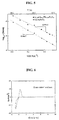
- the garnet-type oxides may have an ionic conductivity of 6.0 ⁇ 10 -4 S/cm or more at 25°C.
- the garnet-type oxides of the solid ion conductors may have an ionic conductivity of 6.5 ⁇ 10 -4 S/cm or more at 25°C.
- the garnet-type oxides of the solid ion conductors may have an ionic conductivity of 7.0 ⁇ 10 -4 S/cm or more at 25°C.
- the garnet-type oxides of the solid ion conductors may have an ionic conductivity of 7.5 ⁇ 10 -4 S/cm or more at 25°C.
- the garnet-type oxides of the solid ion conductors may have an ionic conductivity of 8.0 ⁇ 10 -4 S/cm or more at 25°C.
- the garnet-type oxides of the solid ion conductors may have an ionic conductivity of 8.3 ⁇ 10 -4 S/cm or more at 25°C.
- the garnet-type oxides may have an activation energy that is less than 0.34 eV at a temperature of about -10°C to about 100°C.
- the garnet-type oxides of the solid ion conductors may have an activation energy of 0.30 eV or less at a temperature of about -10°C to about 100°C.
- the garnet-type oxides of the solid ion conductors may have an activation energy of 0.29 eV or less at a temperature of about -10°C to about 100°C.
- the activation energy decreases, the ionic conductivity of the solid ion conductor according to temperature becomes insensitive to temperature, and thus, the solid ion conductor may have good low-temperature properties.
- a solid electrolyte includes the solid ion conductor described above. Due to the inclusion of the solid ion conductor having a novel structure, the solid electrolyte has a high ionic conductivity, a high chemical stability, and a wide potential window, and thus, may be used as an electrolyte for batteries, such as a lithium battery and the like.
- the solid electrolyte may further include a conventional solid ion conductor, in addition to the solid ion conductor including the garnet-type oxide of Formula 4.
- a conventional solid ion conductor may be a general sulfide-based conductor or a general oxide-based conductor.
- Non-limiting examples of the general solid ion conductor include Li 3 N, LISICON(Lithium Super Ionic Conductor), LIPON(Li 3 - y PO 4-x N x , 0 ⁇ y ⁇ 3, 0 ⁇ x ⁇ 4), Thio-LISICON(Li 3.25 Ge 0.25 P 0.75 S 4 ), Li 2 S, Li 2 S-P 2 S 5 , Li 2 S-SiS 2 , Li 2 S-GeS 2 , Li 2 S-B 2 S 5 , Li 2 S-Al 2 S 5 , and Li 2 O-Al 2 O 3 -TiO 2 -P 2 O 5 (LATP). Also, any solid ion conductor known in the art may be used.
- the solid electrolyte may be in the form of powder or a solid.
- the solid form may be, for example, a pellet, a thin film, or the like, but is not limited thereto.
- the solid electrolyte may have various forms according to the use purpose thereof.
- the solid electrolyte may be in the form of ceramic, and it can be prepared by a deposition method, such as sputtering, PLD (pulsed plasma laser); spin coating method; and the like.
- an all-solid-state lithium battery includes the solid electrolyte including the solid ion conductor having a novel structure described above.
- the all-solid-state lithium battery includes a novel solid electrolyte having an improved ionic conductivity, the all-solid-state lithium battery has a reduced interface resistance, and thus, polarization thereof may decrease. Therefore, the all-solid-state lithium battery may have an increased energy efficiency.
- the all-solid-state lithium battery may include a positive electrode, a negative electrode, and the solid electrolyte disposed between the positive electrode and the negative electrode. Also, the all-solid-state lithium battery may further include polymer electrolyte membranes each between the positive electrode and the solid electrolyte and between the negative electrode and the solid electrolyte. Due to the inclusion of the polymer electrolyte membrane, adhesion between the solid electrolyte and the positive electrode and/or the negative electrode is improved, and thus, battery characteristics may be improved.
- the polymer electrolyte membrane may be impregnated in an organic electrolytic solution including a lithium salt and an organic solvent.
- the all-solid-state lithium battery may be prepared as follows:
- the positive electrode may be prepared by forming a positive active material layer including a positive active material on a current collector.
- the positive active material layer may be prepared using a vapor-state method or a solid-state method.
- the vapor-state method include pulse laser deposition (PLD), sputtering deposition, and chemical vapor deposition (CVD).
- PLD pulse laser deposition
- CVD chemical vapor deposition
- the vapor-state method is not limited thereto, and any vaporization method known in the art may be used.
- the solid-state method include a sintering method, a sol-gel method, a doctor-blade method, screen printing, slurry casting, and powder compression.
- the solid-state method is not limited thereto, and any solid-state method known in the art may be used.
- the positive active material may be any one of various materials that are generally used in lithium batteries.
- the positive active material may be a lithium transition metal oxide, a transition metal sulfide, or the like.
- the positive active material may include one or more composite oxides of lithium and a metal selected from the group consisting of cobalt, manganese, nickel, and combinations thereof.
- the positive active material may be a compound represented by any one of the Formulae: Li a A 1-b B b D 2 where 0.90 ⁇ a ⁇ 1.8 and 0 ⁇ b ⁇ 0.5; Li a E 1-b B b O 2-c D c where 0.90 ⁇ at ⁇ 1.8, 0 ⁇ b ⁇ 0.5, and 0 ⁇ c ⁇ 0.05; LiE 2 - b B b O 4-c D c where 0 ⁇ b ⁇ 0.5 and 0 ⁇ c ⁇ 0.05; Li a Ni 1-b-c Co b B c D ⁇ where 0.90 ⁇ at 1.8, 0 ⁇ b ⁇ 0.5, 0 ⁇ c ⁇ 0.05, and 0 ⁇ ⁇ ⁇ 2; Li a Ni 1-b-c Co b
- A is Ni, Co, Mn, or a combination thereof
- B is Al, Ni, Co, Mn, Cr, Fe, Mg, Sr, V, a rare-earth element, or a combination thereof
- D is O, F, S, P, or a combination thereof
- E is Co, Mn, or a combination thereof
- F is F, S, P, or a combination thereof
- G is Al, Cr, Mn, Fe, Mg, La, Ce, Sr, V, or a combination thereof
- Q is Ti, Mo, Mn, or a combination thereof
- I is Cr, V, Fe, Sc, Y, or a combination thereof
- J is V, Cr, Mn, Co, Ni, Cu, or a combination thereof.
- the positive active material layer may further include the solid ion conductor described above, in addition to the positive active material. Due to the inclusion of the solid ion conductor, an interfacial resistance between the positive active material layer and a layer of the solid electrolyte that contacts the positive electrode may be reduced, ionic conductivity in the positive active material layer may be improved, and thermal stability of the positive electrode may be improved.
- the positive active material layer may further include a conductive agent and a binder. Any conductive agent and binder that may be used in the art may be used.
- the negative electrode may be prepared using the same method used to prepare the positive electrode, except that a negative active material is used instead of the positive active material.
- the negative electrode may also further include the solid ion conductor described above in a negative active material layer.
- a negative active material may be any material that is generally used in lithium batteries.
- the negative active material may be at least one selected from the group consisting of lithium metal, a metal that may be alloyed with lithium, a transition metal oxide, a non-transition metal oxide, and a carbonaceous material.
- Examples of the metal that may be alloyed with lithium include Si; Sn; Al; Ge; Pb; Bi; Sb; an Si-Y alloy where Y is an alkali metal, an alkali earth metal, a Group XIII element, a Group XIV element, a transition metal, a rare-earth element, or a combination thereof and is not Si; and an Sn-Y alloy where Y is an alkali metal, alkali earth metal, a Group XIII element, a Group XIV element, a transition metal, a rare-earth element, and a combination thereof and is not Sn.
- the element Y may be Mg, Ca, Sr, Ba, Ra, Sc, Y, Ti, Zr, Hf, Rf, V, Nb, Ta, Db, Cr, Mo, W, Sg, Tc, Re, Bh, Fe, Pb, Ru, Os, Hs, Rh, Ir, Pd, Pt, Cu, Ag, Au, Zn, Cd, B, Al, Ga, Sn, In, Ti, Ge, P, As, Sb, Bi, S, Se, Te, Po, or a combination thereof.
- Non-limiting examples of the transition metal oxide include lithium titanium oxide, vanadium oxide, and lithium vanadium oxide.
- the non-transition metal oxide may be SnO 2 or SiO x where 0 ⁇ x ⁇ 2.
- Examples of the carbonaceous material include crystalline carbon, amorphous carbon, and mixtures thereof.
- Examples of the crystalline carbon include natural graphite and artificial graphite, each of which has an amorphous shape, a plate shape, a flake shape, a spherical shape, or a fiber shape.
- Examples of the amorphous carbon include soft carbon (low-temperature calcined carbon), hard carbon, mesophase pitch carbide, and calcined coke.
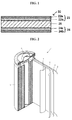
- FIG. 1 is a diagram of an all-solid-state lithium battery 30 according to an embodiment of the present invention.
- the all-solid-state lithium battery 30 includes a solid electrolyte layer 20, a positive electrode 22 disposed on a top surface of the solid electrolyte layer 20, and a negative electrode 24 disposed on a bottom surface of the solid electrolyte layer 20.
- the positive electrode 22 includes a positive active material layer 22b that contacts the solid electrolyte layer 20 and a positive current collector 22a that contacts the positive active material layer 22b.
- the negative electrode 24 includes a negative active material layer 24a that contacts the solid electrolyte layer 20 and a negative current collector 24b that contacts the negative active material layer 24a.
- the all-solid-state lithium battery 30 may be manufactured using a solid-state method, a vapor-state method, or a combination thereof.
- a positive electrode and a negative electrode may be formed respectively on both sides of the solid electrolyte layer 20 by using a vapor-state method, a solid-state method, or a combination thereof, and then current collectors are respectively formed on the positive and negative electrodes, thereby completing the manufacture of the all-solid-state lithium battery 30.
- the negative active material layer 24a, the solid electrolyte layer 20, the positive active material layer 22b, and the positive current collector 22a may be sequentially stacked on the negative current collector 24b by using a vapor-state method, a solid-state method, or a combination thereof, thereby completing the manufacture of the all-solid-state lithium battery 30.
- a lithium battery includes: a positive electrode including a positive active material; a negative electrode including a negative active material; and an organic electrolytic solution, wherein at least one of the positive electrode, the negative electrode, and the organic electrolytic solution includes the solid ion conductor described above.
- the lithium battery may have an improved lifetime characteristic and thermal stability.
- the positive electrode may include the solid ion conductor.
- the amount of the solid ion conductor in the positive electrode may be in a range of about 0 to about 50 wt% based on a total weight of the positive active material and the solid ion conductor.
- the amount of the solid ion conductor in the positive electrode may be in a range of about 0 to about 30 wt% based on the total weight of the positive active material and the solid ion conductor.
- the amount of the solid ion conductor in the positive electrode may be in a range of about 0 to about 10 wt% based on the total weight of the positive active material and the solid ion conductor.
- a capacity of the lithium battery may be reduced.
- a particle diameter of the solid ion conductor may be smaller than a particle diameter of the positive active material particles.
- the negative electrode of the lithium battery may include the solid ion conductor.
- the amount of the solid ion conductor in the negative electrode may be in a range of about 0 to about 50 wt% based on a total weight of the negative active material and the solid ion conductor.
- the amount of the solid ion conductor in the negative electrode may be in a range of about 0 to about 30 wt% based on the total weight of the negative active material and the solid ion conductor.
- the amount of the solid ion conductor in the negative electrode may be in a range of about 0 to about 10 wt% based on the total weight of the negative active material and the solid ion conductor.
- a capacity of the lithium battery may be reduced.
- a particle diameter of the solid ion conductor may be smaller than a particle diameter of the negative active material particles.
- the organic electrolytic solution and/or a separator may include the solid ion conductor.
- a coating layer including the solid ion conductor may be formed on a surface of at least one of the positive active material and the negative active material.
- the coating layer may prevent a side reaction between the positive active material and the organic electrolyte during charging and discharging of the lithium battery, deterioration of the positive and negative active materials due to elution of metal ions therefrom may be prevented, and generation of an unnecessary gas from the positive and negative active materials may be suppressed.
- a solid ion conductor film may be disposed on a surface of at least one of the positive electrode and the negative electrode that is proximate to the organic electrolyte.
- the solid ion conductor film may be formed on a surface of a positive active material layer and/or a negative active material layer which is proximate to the organic electrolytic solution.
- the solid ion conductor film may suppress a side reaction between the organic electrolytic solution and the positive active material layer and/or the negative active material layer and may also suppress the formation of a dendrite.
- the lithium battery including the organic electrolytic solution may be manufactured as follows:
- a positive electrode plate is prepared.
- a positive active material, a conductive agent, a binder, and a solvent are mixed together to prepare a positive active material composition.
- the positive active material composition is directly coated on an Al current collector and dried, thereby completing the manufacture of the positive electrode plate.
- the positive active material composition is cast on a separate support and peeled off from the support to obtain a film, and then the film is laminated on the Al current collector, thereby completing the manufacture of the positive electrode plate.
- the positive active material composition is prepared in the form of an electrode ink including an excess amount of a solvent and printed on a support by inkjet printing or Gravure printing, thereby completing the manufacture of the positive electrode plate.
- the printing method is not limited to the above examples, and any method that may be used in general coating and printing may be used.
- the positive active material composition may further include the solid ion conductor.
- the amount of the solid ion conductor in the positive active material composition may be 50 wt% or less of the total weight of the positive active material and the solid ion conductor.
- the positive active material used in the positive electrode may be the same as that used in the all-solid-state lithium battery described above.
- the conductive agent may be, for example, carbon black.
- the binder include a vinylidene fluoride/hexafluoropropylene copolymer, polyvinylidene fluoride, polyacrylnitrile, polymethylmethacrylate, polytetrafluoroethylene, mixtures of these materials, polyimide, polyamideimide, a styrene-butadiene rubber-based polymer, acrylate-based rubber, and sodium carboxymethylcellulose.
- the solvent may be, for example, N-methylpyrrolidone, acetone, water, or the like.
- Suitable amounts of the positive active material, the conductive agent, the binder, and the solvent are amounts that are used in a general lithium battery.
- a negative active material, a conductive agent, a binder, and a solvent are mixed together to prepare a negative active material composition.
- the negative active material composition is directly coated on a Cu current collector and dried, thereby completing the manufacture of the negative electrode plate.
- the negative active material composition is cast on a separate support and peeled off from the support to obtain a negative active material film, and then the negative active material film is laminated on the Cu current collector, thereby completing the manufacture of the negative electrode plate.
- the negative active material composition is prepared in the form of an electrode ink including an excess amount of a solvent and printed on a support by inkjet printing or Gravure printing, thereby completing the manufacture of the negative electrode plate.
- the printing method is not limited to the above examples, and any method that may be used in general coating and printing may be used.
- a solid ion conductor coating layer may be further formed on a positive active material layer of the positive electrode plate.
- the solid ion conductor coating layer may be formed using any one of various methods known in the art, such as a vaporization method, a solid-state reaction method, or the like.
- the solid ion conductor coating layer may be formed by coating and drying a slurry including the solid ion conductor.
- the negative active material composition may further include the solid ion conductor.
- the amount of the solid ion conductor in the negative active material composition may be 50 wt% or less of the total weight of the negative active material and the solid ion conductor.
- the negative active material used in the negative electrode may be the same as that used in the all-solid-state lithium battery described above.
- the conductive agent, the binder, and the solvent may be the same as those used in the manufacture of the positive electrode plate. Suitable amounts of the negative active material, the conductive agent, the binder, and the solvent are amounts that are used in a general lithium battery.
- a plasticizer may be added to the positive active material composition and the negative active material composition, and thus, pores may be formed in the positive and negative electrode plates.
- the positive electrode and the negative electrode may be separated by the separator, and any separator that may be generally used in a lithium battery may be used.
- the separator has low resistance to migration of ions in an electrolyte and has a high electrolyte-retaining ability.
- the separator include glass fiber, polyester, Teflon ® , polyethylene, polypropylene, polytetrafluoroethylene (PTFE), and combinations thereof, each of which may be nonwoven or woven fabric form.
- PTFE polytetrafluoroethylene
- a windable separator including polyethylene, polypropylene, or the like may be used in a lithium ion battery.
- a separator capable of retaining a large amount of an organic electrolytic solution may be used in a lithium-ion polymer battery.
- the separator may be prepared as follows: A polymer resin, a filler, and a solvent are mixed to prepare a separator composition.
- the separator composition is directly coated on an electrode and then dried to form a separator film.
- the separator composition may be cast on a separate support, dried, detached from a separator support, and finally laminated on an upper portion of the electrode, thereby forming a separator film.
- the polymer resin is not particularly limited, and any polymer resin that is used as an adhesive material of the positive and negative electrode plates may be used.
- the polymer resin include a vinylidenefluoride/hexafluoropropylene copolymer, polyvinylidenefluoride, polyacrylonitrile, polymethylmethacrylate, and mixtures thereof.
- a vinylidenefluoride/hexafluoropropylene copolymer including about 8 to about 25 wt% of hexafluoropropylene may be suitably used.
- the electrolyte may be a liquid electrolyte including an organic electrolytic solution.
- the organic electrolytic solution may be prepared by dissolving a lithium salt in an organic solvent.
- any organic solvent used in the art may be used.
- the organic solvent include propylene carbonate, ethylene carbonate, fluoroethylene carbonate, butylene carbonate, dimethyl carbonate, diethyl carbonate, methylethyl carbonate, methylpropyl carbonate, ethylpropyl carbonate, methylisopropyl carbonate, dipropyl carbonate, dibutyl carbonate, benzonitrile, acetonitrile, tetrahydrofuran, 2-methyltetrahydrofuran, y-butyrolactone, dioxorane, 4-methyldioxorane, N,N-dimethyl formamide, dimethyl acetamide, dimethylsulfoxide, dioxorane, 1,2-dimethoxyethane, sulforane, dichloroethane, chlorobenzene, nitrobenzene, diethylene glycol, dimethyl ether, and mixtures thereof.
- any lithium salt used in the art may be used.
- the lithium salt include LiPF 6 , LiBF 4 , LiSbF 6 , LiAsF 6 , LiClO 4 , LiCF 3 SO 3 , Li(CF 3 SO 2 ) 2 N, LiC 4 F 9 SO 3 , LiAlO 2 , LiAlCl 4 , LiN(C x F 2x+1 SO 2 )(C y F 2y+1 SO 2 ) where x and y are different from each other and each independently are an integer of 1 to 20, LiCl, Lil, and mixtures thereof.
- the amount of the lithium salt may be in a range of about 0.01 M to about 2.0 M, but is not limited thereto.
- the amount of the lithium salt may be appropriately selected within the range that provides an improved battery performance.
- the organic electrolytic solution may further include a flame retardant material such as a phosphorus-based flame retardant material or a halogen-based flame retardant material.
- a flame retardant material such as a phosphorus-based flame retardant material or a halogen-based flame retardant material.
- FIG. 2 is a diagram of a lithium battery 1 including an organic electrolytic solution, according to another embodiment of the present invention.
- the lithium battery 1 including an organic electrolytic solution includes a positive electrode 3, a negative electrode 2, and a separator 4.
- the positive electrode 3, the negative electrode 2, and the separator 4 are wound or folded and then accommodated in a battery case 5. Subsequently, the organic electrolyte is injected into the battery case 5 and the battery case 5 is sealed by a cap assembly 6, thereby completing the manufacture of the lithium battery 1.
- the battery case 5 may be in the form of a cylinder, a rectangle, or a thin film.
- the lithium battery 1 may be a large thin-film-type battery.
- the lithium battery 1 may be a lithium ion battery.
- a separator may be disposed between the positive electrode and the negative electrode to form a battery assembly.
- a plurality of battery assemblies may be stacked in a bi-cell structure and impregnated with an organic electrolytic solution, and the resultant structure is accommodated in a pouch and sealed, thereby completing the manufacture of a lithium ion polymer battery.
- the battery assemblies may be stacked on each other to form a battery pack, and the battery pack may be used in high capacity and high-performance devices, such as a notebook computer, a smart phone, an electric vehicle, and the like.
- the lithium battery Since the lithium battery has high thermal stability and high-rate characteristics, the lithium battery is suitable for use in an electric vehicle (EV).
- the lithium battery may be used in a hybrid vehicle such as a plug-in hybrid electric vehicle (PHEV).
- the lithium battery may be used in fields such as electricity storage systems that store a large amount of electricity, and the like.
- a lithium air battery includes the solid ion conductor described above. Due to the inclusion of the solid ion conductor, the lithium air battery may have an improved stability and energy efficiency.
- the lithium air battery includes a positive electrode, a negative electrode, and a separator, in which an ion conductive membrane including the solid ion conductor may be disposed on a surface of at least one of the positive electrode, the negative electrode, and the separator.
- the ion conductive membrane including the solid ion conductor may be formed on a surface of the negative electrode facing the positive electrode, and thus, a side reaction between the negative electrode and an electrolyte may be suppressed, resulting in an improved lifetime of the lithium air battery.
- the ion conductive membrane may be formed on at least a surface of the separator of the lithium air battery. Also, the ion conductive membrane may be formed on a surface of the positive electrode facing the negative electrode.
- the lithium air battery including the ion conductive membrane may be prepared as follows:
- a positive electrode, a negative electrode capable of intercalating and deintercalating lithium, and a separator are prepared.
- An ion conductive membrane including the solid ion conductor may be disposed on a surface of at least one of the positive electrode, the negative electrode, and the separator.
- the negative electrode is mounted on one side of a case, and the positive electrode with the separator is mounted on the other side of the case, opposite to the negative electrode.
- the separator is disposed on the side of the positive electrode, facing the negative electrode.
- an electrolyte is injected between the positive electrode and the negative electrode, a porous current collector is disposed on the positive electrode, and a pressing member that allows air to reach the positive electrode applies pressure to fix the cell, thereby completing the manufacture of the lithium air battery.
- a lithium ion conductive solid electrolyte membrane may be further disposed on one surface of the negative electrode.
- the case may be divided into upper and lower parts that contact the negative and positive electrodes, respectively.
- An insulating resin may be disposed between the upper and lower parts to electrically insulate the positive and negative electrodes from each other.
- the positive electrode may be manufactured as follows: A catalyst for oxidation/reduction of oxygen, a conductive material, and a binder are mixed and an appropriate solvent is added thereto to prepare a positive electrode slurry. The positive electrode slurry is coated on a surface of a current collector and the coated current collector is then dried, optionally followed by press-molding to improve electrode density, thereby completing the manufacture of the positive electrode.
- the conductive material may be porous.
- any positive electrode material with porosity and conductivity may be used without limitation.
- porous carbon-based materials may be used.
- Examples of a carbon-based material include carbon black, graphite, graphene, activated carbon, carbon fibers, and combinations thereof.
- Metallic conductive materials, including metal fibers and metal meshes, may be used.
- Metal powders including copper, silver, nickel, aluminum, and the like may be used.
- Organic conductive materials, such as polyphenylene derivatives, may be used. The above-described conductive materials may be used alone or in combination.
- the catalyst for oxidation/reduction of oxygen examples include precious metal-based catalysts such as platinum, gold, silver, palladium, ruthenium, rhodium, and osmium; oxide-based catalysts such as a manganese oxide, an iron oxide, a cobalt oxide, and a nickel oxide; and organometallic catalysts such as cobalt phthalocyanine.
- precious metal-based catalysts such as platinum, gold, silver, palladium, ruthenium, rhodium, and osmium
- oxide-based catalysts such as a manganese oxide, an iron oxide, a cobalt oxide, and a nickel oxide
- organometallic catalysts such as cobalt phthalocyanine.
- the catalyst is not limited to the above examples and any catalysts for oxidation/reduction of oxygen which are known in the art may be used.
- the catalyst for oxidation/reduction of oxygen may not be used, if desired.
- the catalyst may be supported on a catalyst support.
- the catalyst support may be an oxide, zeolite, clay-based minerals, or carbon.
- the oxide may be at least one oxide selected from the group consisting of alumina, silica, zirconium oxide, and titanium dioxide or may be an oxide including at least one metal selected from the group consisting of cerium (Ce), praseodymium (Pr), samarium (Sm), europium (Eu), terbium (Tb), thulium (Tm), ytterbium (Yb), antimony (Sb), bismuth (Bi), vanadium (V), chromium (Cr), manganese (Mn), iron (Fe), cobalt (Co), nickel (Ni), copper (Cu), niobium (Nb), molybdenum (Mo), and tungsten (W).
- the carbon examples include amorphous carbons such as carbon black, acetylene black, channel black, and lamp black; graphite such as natural graphite, artificial graphite, and expandable graphite; activated carbon; and carbon fibers.
- amorphous carbons such as carbon black, acetylene black, channel black, and lamp black
- graphite such as natural graphite, artificial graphite, and expandable graphite
- activated carbon and carbon fibers.
- the catalyst support is not limited to the above examples and any catalyst support known in the art may be used.
- the binder may include a thermoplastic resin or a thermosetting resin.
- the binder include, but are not limited to, polyethylene, polypropylene, polytetrafluoroethylene (PTFE), polyvinylidene fluoride (PVDF), styrene-butadiene rubber, a tetrafluoroethylene-perfluoroalkylvinylether copolymer, a vinylidene fluoride-hexafluoropropylene copolymer, a vinylidene fluoride-chlorotrifluoroethylene copolymer, an ethylene-tetrafluoroethylene copolymer, polychlorotrifluoroethylene, a vinylidene fluoride-pentafluoro propylene copolymer, a propylene-tetrafluoroethylene copolymer, an ethylene-chlorotrifluoroethylene copolymer, a vinylidene fluoride-hexafluoropropy
- a porous body in a matrix or mesh form may be used as the current collector to facilitate diffusion of oxygen.
- a porous metal plate made of, for example, stainless steel, nickel, or aluminum may be used.
- Materials for the current collector are not particularly limited, and any material for current collectors known in the art may be used.
- the current collector may be coated with an anti-oxidative metal or alloy to prevent oxidation.
- a material for the negative electrode capable of intercalating and deintercalating lithium may be Li metal, a Li metal-based alloy, or a material capable of intercalating and deintercalating lithium, but is not limited thereto.
- any material which may be used in the art that includes lithium or is capable of intercalating and deintercalating lithium may be used.
- the negative electrode determines the capacity of the lithium air battery and thus the negative electrode may be, for example, lithium metal.
- the lithium metal-based alloy may be an alloy of lithium with aluminum, tin, magnesium, indium, calcium, titanium, or vanadium.
- the type of the negative electrode is not particularly limited.
- the negative electrode may be in the form of a sheet.
- the separator disposed between the positive electrode and the negative electrode is not particularly limited as long as it has a composition that can withstand service conditions of the lithium air battery.
- the separator include polymer nonwoven fabrics such as polypropylene nonwoven fabrics and polyphenylene sulfide nonwoven fabrics; and porous films composed of olefin resins such as polyethylene and polypropylene. These materials may also be used in combination.
- the separator may not be used, if desired.
- the electrolyte may be an organic electrolyte or an aqueous electrolyte.
- the organic electrolyte may include an aprotic solvent.
- the aprotic solvent may be a carbonate-based solvent, an ester-based solvent, an ether-based solvent, a ketone-based solvent, an amine-based solvent, or a phosphine-based solvent.
- Examples of the carbonate-based solvent include dimethyl carbonate (DMC), diethyl carbonate (DEC), ethyl methyl carbonate (EMC), dipropyl carbonate (DPC), methyl propyl carbonate (MPC), ethyl propyl carbonate (EPC), methyl ethyl carbonate (MEC), ethylene carbonate (EC), propylene carbonate (PC), and butylene carbonate (BC).
- ester-based solvent examples include methyl acetate, ethyl acetate, n-propyl acetate, dimethylacetate, methyl propionate, ethyl propionate, y-butyrolactone, decanolide, valerolactone, mevalonolactone, and caprolactone.
- ether-based solvent examples include dibutyl ether, tetraglyme, diglyme, dimethoxyethane, 2-methyltetrahydrofuran, and tetrahydrofuran.
- the ketone-based solvent may be cyclohexanone.
- the amine-based solvent examples include triethylamine and triphenylamine.
- the phosphine-based solvent may be triethylphosphine.
- the aprotic solvent is not limited to the above examples, and any aprotic solvent known in the art may be used.
- aprotic solvent examples include: nitriles such as R-CN where R is a linear, branched, or cyclic C 2 to C 20 hydrocarbon group and has a double-bond aromatic ring or ether bond; amides such as dimethylformamide; dioxolanes such as 1,3-dioxolane; and sulfolanes.
- the aprotic solvent may be used alone or in combination.
- a mixed ratio may be appropriately adjusted according to the desired performance of the battery to be manufactured and may be obvious to one of ordinary skill in the art.
- the organic electrolyte may include an ionic liquid.
- the ionic liquid include linear or branched, substituted compounds containing cations such as ammonium, imidazolium, pyrrolidinium, and piperidinium, and anions such as PF 6 - , BF 4 - , CF 3 SO 3 - , (CF 3 SO 2 ) 2 N - , (C 2 F 5 SO 2 ) 2 N - , (C 2 F 5 SO 2 ) 2 N - , and (CN) 2 N - .
- the organic electrolyte may include at least one of an alkali metal salt and an alkali earth metal salt.
- the at least one of the alkali metal salt and the alkali earth metal salt is dissolved in an organic solvent and acts as a source of at least one of the alkali metal ions and the alkali earth metal ions in the lithium air battery.
- the salt may facilitate migration of the alkali metal ions and/or alkali earth metal ions between the positive and negative electrodes.
- cations of the alkali metal salt and/or the alkali earth metal salt may include lithium ions, sodium ions, magnesium ions, potassium ions, calcium ions, rubidium ions, strontium ions, cesium ions, barium ions, and the like.
- Anions of the alkali metal salt and/or alkali earth metal salt in the organic electrolyte may be at least one anion selected from the group consisting of PF 6 - , BF 4 - , SbF6 - , AsF 6 - , C 4 F 9 SO 3 - , ClO 4 - , AlO 2 - , AlCl 4 - , C x F 2x+1 SO 3 - where x is a natural number, (C x F 2x+1 SO 2 )(C y F 2y+1 SO 2 )N - where x and y are natural numbers, and a halide.
- the alkali metal salt and/or alkali earth metal salt may be, but are/is not limited to, at least one compound selected from the group consisting of LiPF 6 , LiBF 4 , LiSbF 6 , LiAsF 6 , LiN(SO 2 C 2 F 5 ) 2 , Li(CF 3 SO 2 ) 2 N, LiC 4 F 9 SO 3 , LiClO 4 , LiAlO 2 , LiAlCl 4 , LiN(C x F 2x+1 SO 2 )(C x F 2y+1 SO 2 ) where x and y are natural numbers, LiF, LiBr, LiCl, Lil, and LiB(C 2 O 4 ) 2 (LiBOB; lithium bis(oxalato)borate). Any alkali metal salts and/or alkali earth metal salts available in the art may be used.
- the amount of the at least one of the alkali metal salt and the alkali earth metal salt may be from about 100 mM to about 10 M, for example, from about 500 mM to about 2 M.
- the amount of the at least one of the alkali metal salt and the alkali earth metal salt is not particularly limited, as long as the organic electrolyte may effectively transfer lithium ions and/or electrons during charging and discharging.
- a lithium ion conductive solid electrolyte membrane may be disposed between the negative electrode and the electrolyte.
- the lithium ion conductive solid electrolyte membrane may serve as a protective layer preventing water contained in an aqueous electrolyte and impurities, such as oxygen, from directly reacting with lithium contained in the negative electrode.
- a material for the lithium ion conductive solid electrolyte membrane may be an inorganic material, for example, lithium ion conductive glass, lithium ion conductive crystal (ceramic or glass-ceramic), or a mixture thereof.
- the electrolyte membrane material is not limited to the above examples and any material known in the art for a solid electrolyte membrane which has lithium ion conductivity and can protect the negative electrode may be used.
- the material for the lithium ion conductive solid electrolyte membrane may be an oxide.
- the lithium ion conductive solid electrolyte membrane may include a solid ion conductor including the garnet-type oxide of Formula 4 described above.
- the lithium ion conductive solid electrolyte membrane may further include a general lithium ion conductive crystal.
- the lithium ion conductive crystal may be Li 1+x+y (Al, Ga) x (Ti, Ge) 2-x Si y P 3-y O 12 where 0 ⁇ x ⁇ 1 and 0 ⁇ y ⁇ 1, for example, 0 ⁇ x ⁇ 0.4 and 0 ⁇ y ⁇ 0.6, for example, 0.1 ⁇ x ⁇ 0.3, and 0.1 ⁇ y ⁇ 0.4.
- lithium-aluminum-germanium-phosphate LAGP
- lithium-aluminum-titanium-phosphate LATP
- lithium-aluminum-titanium-silicon-phosphate LATSP
- the lithium ion conductive solid electrolyte membrane may further include a polymer solid electrolyte, in addition to the glass-ceramic.
- the polymer solid electrolyte may be polyethylene oxide doped with a lithium salt.
- the lithium salt include LiN(SO 2 CF 2 CF 3 ) 2 , LiBF 4 , LiPF 6 , LiSbF 6 , LiAsF 6 , LiClO 4 , LiCF 3 SO 3 , LiN(SO 2 CF 3 ) 2 , LiN(SO 2 C 2 F 5 ) 2 , LiC(SO 2 CF 3 ) 3 , LiN(SO 3 CF 3 ) 2 , LiC 4 F 9 SO 3 , LiAlCl 4 , and the like.
- the a polymer solid electrolyte may be PMMA(polymethylmetaacrylate), PPO(Polypropylene oxide), PVdF(polyvinylidene fluoride), PS(Polystyrene), PVC(polyvinyl chloride), PVA(polyvinyl alcohol), PAN(polyacrylonitrile), PES(polyester sulfide), derivatives thereof, other polymers comprising ion dissociatable groups and the like.
- the lithium ion conductive solid electrolyte membrane may further include an inorganic solid electrolyte, in addition to the glass-ceramic.
- examples of the inorganic solid electrolyte include Cu 3 N, Li 3 N, LiPON, and the like.
- the lithium air battery may be either a lithium primary battery or a lithium secondary battery.
- the lithium air battery may have various shapes, and in some embodiments, may have a coin, button, sheet, stack, cylinder, plane, or horn shape.
- the lithium air battery may be used as a large-scale battery for electric vehicles.
- FIG. 3 is a diagram illustrating a lithium air battery 10 according to another embodiment of the present invention.
- the lithium air battery 10 includes a positive electrode 15 using oxygen as an active material and disposed on a first current collector 14, a negative electrode 13 including lithium and contacting a second current collector 12, an organic electrolyte 18 disposed between the positive electrode 15 and the negative electrode 13, and a separator 16 disposed on one surface of the positive electrode 15.
- a lithium ion conductive solid electrolyte membrane (not shown) may be disposed on one surface of the negative electrode 13.
- the first current collector 14, which is porous, may serve as a gas diffusion layer.
- a pressing member 19 that allows air to reach the positive electrode 15 may be disposed on the first current collector 14.
- a case 11 formed of an insulating resin is disposed between the positive electrode 15 and the negative electrode 13 to electrically insulate the positive electrode 15 and the negative electrode 13. Air is supplied to an air inlet 17a and exhausted via an air outlet 17b.
- air is not limited to atmospheric air, and may refer to a combination of gases including oxygen, or pure oxygen gas. This broad definition of “air” also applies to other terms including “air battery” and “air electrode.”
- a method of preparing a solid ion conductor includes: mixing precursors of a solid ion conductor; and sintering a mixture of the precursors in an air atmosphere at a temperature of about 800°C to about 1250°C for about 2 to about 40 hours.
- the sintering process may be performed at a temperature of about 900°C to about 1200°C for about 5 to about 30 hours.
- the precursors of the solid ion conductor may be precursors of metals contained in the solid ion conductor, and any precursor of a solid ion conductor available in the art may be used.
- sintering reactivity When the sintering temperature is too low, sintering reactivity may be insufficient. On the other hand, when the sintering temperature is too high, phase decomposition may occur or lithium may volatilize. In addition, when the sintering time is too short, sintering reactivity may be insufficient. On the other hand, when the sintering time is too long, lithium may volatilize.
- the mixing of the precursors of the solid ion conductor may be performed using a ball mill.
- the method may further include preliminarily sintering the mixture of the precursors of a solid ion conductor at a relatively low temperature, before the sintering process.
- the preliminary sintering process may be performed twice or more times.
- the solid ion conductor prepared using the preparation method may have various forms, such as powder, a thin film, a pellet, and the like, and may be appropriately selected according to the use thereof.
- the mixture was pulverized by mixing in an isopropyl alcohol solvent by using a planetary ball mill (400 rpm, zirconia oxide balls) for 6 hours.
- the pulverized mixed powder was put in an alumina crucible and sintered in an air atmosphere at 900°C for 12 hours.
- an excess amount of LiOH corresponding to 10 wt% (the amount of Li) based on the amount of Li in the composition of a final product.
- the mixture with LiOH added thereto was pulverized by mixing in an isopropyl alcohol solvent by using a planetary ball mill (500 rpm, zirconia oxide balls) for 6 hours.
- the sintered powder was molded in the form of a pellet or a thin film or was not molded, and sintered in an air atmosphere at 1100°C for 20 hours, thereby completing the preparation of a solid ion conductor.
- a solid ion conductor was prepared in the same manner as in Example 1, except that a stoichiometric mixing ratio of the starting materials was changed to obtain Li 7 La 3 Zr 2 O 12 .
- a solid ion conductor was prepared in the same manner as in Example 1, except that a stoichiometric mixing ratio of the starting materials was changed to obtain Li 9 RbLa 2 Zr 2 O 12 .
- Pt was deposited on both surfaces of each of the pellet-type solid ion conductors of Examples 1 to 6 by using a sputter to form a shield electrode.
- An impedance of each pellet with the shield electrode formed thereon was measured by a 2-probe method by using a Solatron Sl1260 impedance/gain-phase analyzer. A frequency range was from 0.1 Hz to 1 MHz, and an amplitude voltage was 20 mV.
- the impedance was measured in an air atmosphere at 25°C. Resistance values were obtained from an arc of a Nyquist plot for the impedance measurement results and ionic conductivity of each sample was calculated therefrom. The results are shown in Table 1 and FIG. 4 .
- Example 1 8.3 x 10 -4 Example 2 6.3 x 10- 4 Example 3 5.7 x 10 -4 Example 4 2.1 x 10 -5 Example 5 4.1 x 10 -5 Example 6 5.3 x 10 -4 Comparative Example 1 2.0 x 10 -4 Comparative Example 2 4.5 x 10 -6
- solid ion conductors of Examples 1 to 6 exhibited a higher ionic conductivity than that of the solid ion conductors of Comparative Examples 1 and 2.
- embodiments of the solid ion conductors according to Formula 4 may have improved characteristics when x+2y ⁇ 2.5, in particular when y ⁇ 0.25.
- the activation energy of the solid ion conductor of Example 2 was decreased to 2.9 eV, i.e., by 0.5 eV, as compared to 3.4 eV of the solid ion conductor of Comparative Example 1.
- a solid ion conductor has a structure in which at least a portion of trivalent cations existing at the dodecahedral site is substituted with a monovalent cation, and thus, has an improved ionic conductivity.
- various types of lithium batteries including the solid ion conductors are provided.
Description
- The present disclosure relates to solid ion conductors, solid electrolytes including the solid ion conductors, lithium batteries including the solid electrolytes, and methods of manufacturing the lithium batteries.
- Lithium batteries have high voltage and energy density, and thus, are used in various applications. For example, the field of electric vehicles, for example, hybrid electric vehicles (HEVs) and plug-in hybrid electric vehicles (PHEVs), requires operation at high temperatures, charging or discharging a large amount of electricity, and a long period of use.
- When an electrode to which a high voltage (e.g., 5 V or more) is applied is used in a lithium battery including a liquid electrolyte prepared by dissolving a lithium salt in an organic solvent, the lithium battery is chemically unstable. In addition, the liquid electrolyte starts to decompose at a voltage of 2.5 V or more. The liquid electrolyte has a high risk of leakage, fire, and explosion. Further, the liquid electrolyte can be grown into a dendrite form, thus can cause self-discharging and heating of a lithium battery.
- As an example of batteries having a higher stability than that of lithium batteries including the liquid electrolyte, all-solid-state lithium batteries including a lithium ion conductor as a solid electrolyte can be considered. The lithium ion conductor constituting the solid electrolyte is a single ion conductor in which only Li ions are migrated, and thus, it has no risk of ignition, as compared to lithium batteries including a liquid electrolyte. Therefore, all-solid-state lithium batteries are suitable for use in electric vehicles, large-scale storage batteries, and the like.
- The solid ion conductor needs to have high lithium ionic conductivity, be chemically stable, and have a wide potential window, for use as a solid electrolyte for a lithium battery.
- A garnet-type oxide, such as Li5La3M2O12 (M=Nb or Ta), is chemically stable and has a wide potential window, while it has a poor lithium ionic conductivity (e.g., approximately ∼10-6 S/cm) at 25°C.
-
WO 2011/089710 discloses Li7La3Zr2O12 for use as a negative electrode structure for an aqueous electrolyte battery. -
DE 10 2007 030 604 discloses the use of solid ion conductors having a garnet-type structure in batteries, accumulators, electrochromic devices and other electrochromic cells. -
WO 2005/085138 discloses solid lithium ion conductors, a method for the production thereof and the use thereof in batteries, accumulators, supercaps and electrochromical devices. - J. Awaka et al., Journal of Solid State Chemistry 182 (2009) 1046-2052 discloses the synthesis of Li7La3Zr2O12.
-
WO 2010/090301 discloses a garnet-type lithium ion-conducting oxide represented by the formula Li5+xLa3(Zrx, A2-x)O12, wherein A is selected from the group consisting of Sc, Ti, V, Y, Nb, Hf, Ta, Al, Si, Ga, Ge, and Sn and 1.4≤x<2. - Therefore, there is still a need to develop a solid ion conductor having an improved lithium ionic conductivity.
- Provided are solid ion conductors including novel garnet-type oxides.
- Provided are solid electrolytes including the solid ion conductors.
- Provided are all-solid-state lithium batteries including the solid electrolytes.
- Provided are lithium batteries including the solid ion conductors.
- Provided are lithium air batteries including the solid ion conductors.
- Provided are methods of preparing the solid ion conductors.
- Additional aspects will be set forth in part in the description which follows and, in part, will be apparent from the description, or may be learned by practice of the presented embodiments.
- According to an aspect of the present invention, a solid ion conductor includes a garnet-type oxide represented by Formula 4 below:
<Formula 4> Li5+x+2y(Dy, La3-y)Zr2Od
wherein D is K, Rb, or Cs, and
0<x+2y≤3, 0<y≤0.5, and 0<d≤12. - According to another aspect of the present invention, a solid electrolyte includes the solid ion conductor described above.
- According to another aspect of the present invention, an all-solid-state lithium battery includes the solid electrolyte described above.
- According to another aspect of the present invention, a lithium battery includes: a positive electrode including a positive active material; a negative electrode including a negative active material; and an organic electrolytic solution, wherein at least one of the positive electrode, the negative electrode, and the organic electrolytic solution includes the solid ion conductor described above.
- According to another aspect of the present invention, a lithium air battery includes the solid ion conductor described above.
- According to another aspect of the present invention, a method of preparing a solid ion conductor, the method including mixing precursors of the solid ion conductor together; and sintering a mixture of the precursors in an air atmosphere at a temperature of 800°C to 1250°C for 2 to 40 hours.
- These and/or other aspects will become apparent and more readily appreciated from the following description of the embodiments, taken in conjunction with the accompanying drawings in which:
-
FIG. 1 is a diagram of an all-solid-state lithium battery according to an embodiment of the present invention; -
FIG. 2 is a diagram of a lithium battery including an organic electrolytic solution, according to another embodiment of the present invention; -
FIG. 3 is a diagram of a lithium air battery according to another embodiment of the present invention; -
FIG. 4 is a graph showing conductivities of solid ion conductors prepared according to Examples 1 through 6 and Comparative Examples 1 and 2; -
FIG. 5 is a graph showing activation energies of the solid ion conductors of Example 2 and Comparative Example 1; and -
FIG. 6 is a graph showing measurement results of current versus voltage of the solid ion conductor of Example 2. - Reference will now be made in detail to embodiments, examples of which are illustrated in the accompanying drawings, wherein like reference numerals refer to like elements throughout. In this regard, the present embodiments may have different forms and should not be construed as being limited to the descriptions set forth herein. Accordingly, the embodiments are merely described below, by referring to the figures, to explain aspects of the present description. As used herein, the term "and/or" includes any and all combinations of one or more of the associated listed items. Expressions such as "at least one of," when preceding a list of elements, modify the entire list of elements and do not modify the individual elements of the list.
- Hereinafter, solid ion conductors according to one or more exemplary embodiments of the present invention, solid electrolytes including the solid ion conductors, all-solid-state lithium batteries including the solid electrolytes, lithium batteries including an organic electrolytic solution including the solid ion conductors, lithium air batteries including the solid electrolytes, and methods of preparing the solid ion conductors will be described in more detail.
- According to an embodiment of the present invention, a solid ion conductor includes a garnet-type oxide represented by Formula 4 below:
<Formula 4> Li5+x+2y(Dy,La3-y)Zr2Od
- D is K, Rb, or Cs, 0<x+2y≤3, 0<y≤0.5, 0<d≤12, and O may be partially or totally substituted by at least one of a pentavalent anion, a hexavalent anion, and a heptavalent anion.
- For example, in the garnet-type oxide of Formula 4, x and y may satisfy the following condition: 2<x+2y≤3.
- In the solid ion conductors, the garnet-type oxides may have an ionic conductivity of 6.0×10⁻⁴ S/cm or more at 25°C. For example, the garnet-type oxides of the solid ion conductors may have an ionic conductivity of 6.5×10⁻⁴ S/cm or more at 25°C. For example, the garnet-type oxides of the solid ion conductors may have an ionic conductivity of 7.0×10⁻⁴ S/cm or more at 25°C. For example, the garnet-type oxides of the solid ion conductors may have an ionic conductivity of 7.5×10⁻⁴ S/cm or more at 25°C. For example, the garnet-type oxides of the solid ion conductors may have an ionic conductivity of 8.0×10⁻⁴ S/cm or more at 25°C. For example, the garnet-type oxides of the solid ion conductors may have an ionic conductivity of 8.3×10⁻⁴ S/cm or more at 25°C.
- In the solid ion conductors, the garnet-type oxides may have an activation energy that is less than 0.34 eV at a temperature of about -10°C to about 100°C. For example, the garnet-type oxides of the solid ion conductors may have an activation energy of 0.30 eV or less at a temperature of about -10°C to about 100°C. For example, the garnet-type oxides of the solid ion conductors may have an activation energy of 0.29 eV or less at a temperature of about -10°C to about 100°C. As the activation energy decreases, the ionic conductivity of the solid ion conductor according to temperature becomes insensitive to temperature, and thus, the solid ion conductor may have good low-temperature properties.
- According to another embodiment of the present invention, a solid electrolyte includes the solid ion conductor described above. Due to the inclusion of the solid ion conductor having a novel structure, the solid electrolyte has a high ionic conductivity, a high chemical stability, and a wide potential window, and thus, may be used as an electrolyte for batteries, such as a lithium battery and the like.
- The solid electrolyte may further include a conventional solid ion conductor, in addition to the solid ion conductor including the garnet-type oxide of Formula 4. For example, a conventional solid ion conductor may be a general sulfide-based conductor or a general oxide-based conductor. Non-limiting examples of the general solid ion conductor include Li3N, LISICON(Lithium Super Ionic Conductor), LIPON(Li3-yPO4-xNx, 0<y<3, 0<x<4), Thio-LISICON(Li3.25Ge0.25P0.75S4), Li2S, Li2S-P2S5, Li2S-SiS2, Li2S-GeS2, Li2S-B2S5, Li2S-Al2S5, and Li2O-Al2O3-TiO2-P2O5(LATP). Also, any solid ion conductor known in the art may be used. For example, the conventional solid electrolyte may be LLTO(lithium lanthanum titanate, Li0.34La0.51TiO2.94), LTAP(lithium titanium aluminum phosphate, (Li1+xTi2-xAl(PO4)3 (0≤x≤0.4), wherein at least a part of Ti4+ and P5+ may bw substituted with trivalent ion such as Al3+, Ga3+, Sc3+, In3+, Y3+ and the like), Thio-LISICON (Lithium Superlonic conductor, Li4-xM1-yM'y'S4 (M= Si, Ge and M' = P, Al, Zn, Ga) and the like.
- The solid electrolyte may be in the form of powder or a solid. The solid form may be, for example, a pellet, a thin film, or the like, but is not limited thereto. The solid electrolyte may have various forms according to the use purpose thereof. For example, the solid electrolyte may be in the form of ceramic, and it can be prepared by a deposition method, such as sputtering, PLD (pulsed plasma laser); spin coating method; and the like.
- According to another embodiment of the present invention, an all-solid-state lithium battery includes the solid electrolyte including the solid ion conductor having a novel structure described above.
- Since the all-solid-state lithium battery includes a novel solid electrolyte having an improved ionic conductivity, the all-solid-state lithium battery has a reduced interface resistance, and thus, polarization thereof may decrease. Therefore, the all-solid-state lithium battery may have an increased energy efficiency.
- The all-solid-state lithium battery may include a positive electrode, a negative electrode, and the solid electrolyte disposed between the positive electrode and the negative electrode. Also, the all-solid-state lithium battery may further include polymer electrolyte membranes each between the positive electrode and the solid electrolyte and between the negative electrode and the solid electrolyte. Due to the inclusion of the polymer electrolyte membrane, adhesion between the solid electrolyte and the positive electrode and/or the negative electrode is improved, and thus, battery characteristics may be improved. The polymer electrolyte membrane may be impregnated in an organic electrolytic solution including a lithium salt and an organic solvent.
- The all-solid-state lithium battery may be prepared as follows:
- First, a solid electrolyte including the garnet-type oxide described above is prepared.
- Next, a positive electrode is prepared.
- The positive electrode may be prepared by forming a positive active material layer including a positive active material on a current collector. The positive active material layer may be prepared using a vapor-state method or a solid-state method. Examples of the vapor-state method include pulse laser deposition (PLD), sputtering deposition, and chemical vapor deposition (CVD). However, the vapor-state method is not limited thereto, and any vaporization method known in the art may be used. Examples of the solid-state method include a sintering method, a sol-gel method, a doctor-blade method, screen printing, slurry casting, and powder compression. However, the solid-state method is not limited thereto, and any solid-state method known in the art may be used.
- The positive active material may be any one of various materials that are generally used in lithium batteries. For example, the positive active material may be a lithium transition metal oxide, a transition metal sulfide, or the like.
- For example, the positive active material may include one or more composite oxides of lithium and a metal selected from the group consisting of cobalt, manganese, nickel, and combinations thereof. For example, the positive active material may be a compound represented by any one of the Formulae: LiaA1-bBbD2 where 0.90 ≤ a ≤ 1.8 and 0 ≤ b ≤ 0.5; LiaE1-bBbO2-cDc where 0.90 ≤ at ≤ 1.8, 0 ≤ b ≤ 0.5, and 0 ≤ c ≤ 0.05; LiE2-bBbO4-cDc where 0 ≤ b ≤ 0.5 and 0 ≤ c ≤ 0.05; LiaNi1-b-cCobBcDα where 0.90 ≤ at 1.8, 0 ≤ b ≤ 0.5, 0 ≤ c ≤ 0.05, and 0 < α ≤ 2; LiaNi1-b-cCobBcO2-αFα where 0.90 ≤ a ≤ 1.8, 0 ≤ b ≤ 0.5, 0 ≤ c ≤ 0.05, and 0 < α < 2; LiaNi1-b-cCObBcO2-αF2 where 0.90 ≤ a ≤ 1.8, 0 ≤ b ≤ 0.5, 0 ≤ c ≤ 0.05, and 0 < α < 2; LiaNi1-b-cMnbBcDα where 0.90 ≤ a ≤ 1.8, 0 ≤ b ≤ 0.5, 0 ≤ c ≤ 0.05, and 0 < α ≤ 2; LiaNi1-b-cMnbBcO2-αFα where 0.90 ≤ a ≤ 1.8, 0 ≤ b ≤ 0.5, 0 ≤ c ≤ 0.05, and 0 < α < 2; LiaNi1-b-cMnbBcO2-αF2 where 0.90 ≤ a ≤ 1.8, 0 ≤ b ≤ 0.5, 0 ≤ c ≤ 0.05, and 0<α<2; LiaNibEcGdO2 where 0.90 ≤ a ≤ 1.8, 0 ≤ b ≤ 0.9, 0 ≤ c ≤ 0.5, and 0.001 ≤ d ≤ 0.1; LiaNibCocMndGeO2 where 0.90 ≤ a ≤ 1.8, 0 ≤ b ≤ 0.9, 0 ≤ c ≤ 0.5, 0 ≤ d ≤0.5, and 0.001 ≤ e ≤ 0.1; LiaNiGbO2 where 0.90 ≤ a ≤ 1.8 and 0.001 ≤ b ≤ 0.1; LiaCoGbO2 where 0.90 ≤ a ≤ 1.8 and 0.001 ≤ b ≤ 0.1; LiaMnGbO2 where 0.90 ≤ a ≤ 1.8 and 0.001 ≤ b ≤ 0.1; LiaMn2GbO4 where 0.90 ≤ a ≤ 1.8 and 0.001 ≤ b ≤ 0.1; QO2; QS2; LiQS2; V2O5; LiV2O2; LilO2; LiNiVO4; Li(3-f)J2(PO4)3(0 ≤ f ≤ 2); Li(3-f)Fe2(PO4)3 where 0 ≤ f ≤ 2; and LiFePO4.
- In the formulae above, A is Ni, Co, Mn, or a combination thereof; B is Al, Ni, Co, Mn, Cr, Fe, Mg, Sr, V, a rare-earth element, or a combination thereof; D is O, F, S, P, or a combination thereof; E is Co, Mn, or a combination thereof; F is F, S, P, or a combination thereof; G is Al, Cr, Mn, Fe, Mg, La, Ce, Sr, V, or a combination thereof; Q is Ti, Mo, Mn, or a combination thereof; I is Cr, V, Fe, Sc, Y, or a combination thereof; and J is V, Cr, Mn, Co, Ni, Cu, or a combination thereof.
- Examples of the positive active material include LiCoO2, LiMnxO2x where x=1 or 2, LiNi1-xMnxO2x where 0<x<1, Ni1-x-yCoxMnyO2 where 0≤x≤0.5 and 0≤y≤0.5, LiFePO4, TiS2, FeS2, TiS3, and FeS3.
- The positive active material layer may further include the solid ion conductor described above, in addition to the positive active material. Due to the inclusion of the solid ion conductor, an interfacial resistance between the positive active material layer and a layer of the solid electrolyte that contacts the positive electrode may be reduced, ionic conductivity in the positive active material layer may be improved, and thermal stability of the positive electrode may be improved.
- In addition, the positive active material layer may further include a conductive agent and a binder. Any conductive agent and binder that may be used in the art may be used.
- Next, a negative electrode is prepared.
- The negative electrode may be prepared using the same method used to prepare the positive electrode, except that a negative active material is used instead of the positive active material. The negative electrode may also further include the solid ion conductor described above in a negative active material layer.
- A negative active material may be any material that is generally used in lithium batteries. For example, the negative active material may be at least one selected from the group consisting of lithium metal, a metal that may be alloyed with lithium, a transition metal oxide, a non-transition metal oxide, and a carbonaceous material. Examples of the metal that may be alloyed with lithium include Si; Sn; Al; Ge; Pb; Bi; Sb; an Si-Y alloy where Y is an alkali metal, an alkali earth metal, a Group XIII element, a Group XIV element, a transition metal, a rare-earth element, or a combination thereof and is not Si; and an Sn-Y alloy where Y is an alkali metal, alkali earth metal, a Group XIII element, a Group XIV element, a transition metal, a rare-earth element, and a combination thereof and is not Sn. The element Y may be Mg, Ca, Sr, Ba, Ra, Sc, Y, Ti, Zr, Hf, Rf, V, Nb, Ta, Db, Cr, Mo, W, Sg, Tc, Re, Bh, Fe, Pb, Ru, Os, Hs, Rh, Ir, Pd, Pt, Cu, Ag, Au, Zn, Cd, B, Al, Ga, Sn, In, Ti, Ge, P, As, Sb, Bi, S, Se, Te, Po, or a combination thereof.
- Non-limiting examples of the transition metal oxide include lithium titanium oxide, vanadium oxide, and lithium vanadium oxide.
- For example, the non-transition metal oxide may be SnO2 or SiOx where 0<x≤2.
- Examples of the carbonaceous material include crystalline carbon, amorphous carbon, and mixtures thereof. Examples of the crystalline carbon include natural graphite and artificial graphite, each of which has an amorphous shape, a plate shape, a flake shape, a spherical shape, or a fiber shape. Examples of the amorphous carbon include soft carbon (low-temperature calcined carbon), hard carbon, mesophase pitch carbide, and calcined coke.
-
FIG. 1 is a diagram of an all-solid-state lithium battery 30 according to an embodiment of the present invention. Referring toFIG. 1 , the all-solid-state lithium battery 30 includes asolid electrolyte layer 20, apositive electrode 22 disposed on a top surface of thesolid electrolyte layer 20, and anegative electrode 24 disposed on a bottom surface of thesolid electrolyte layer 20. Thepositive electrode 22 includes a positive active material layer 22b that contacts thesolid electrolyte layer 20 and a positivecurrent collector 22a that contacts the positive active material layer 22b. Thenegative electrode 24 includes a negativeactive material layer 24a that contacts thesolid electrolyte layer 20 and a negative current collector 24b that contacts the negativeactive material layer 24a. The all-solid-state lithium battery 30 may be manufactured using a solid-state method, a vapor-state method, or a combination thereof. For example, a positive electrode and a negative electrode may be formed respectively on both sides of thesolid electrolyte layer 20 by using a vapor-state method, a solid-state method, or a combination thereof, and then current collectors are respectively formed on the positive and negative electrodes, thereby completing the manufacture of the all-solid-state lithium battery 30. Alternatively, the negativeactive material layer 24a, thesolid electrolyte layer 20, the positive active material layer 22b, and the positivecurrent collector 22a may be sequentially stacked on the negative current collector 24b by using a vapor-state method, a solid-state method, or a combination thereof, thereby completing the manufacture of the all-solid-state lithium battery 30. - According to another embodiment of the present invention, a lithium battery includes: a positive electrode including a positive active material; a negative electrode including a negative active material; and an organic electrolytic solution, wherein at least one of the positive electrode, the negative electrode, and the organic electrolytic solution includes the solid ion conductor described above.
- Due to the inclusion of the solid ion conductor, the lithium battery may have an improved lifetime characteristic and thermal stability.
- In the lithium battery, the positive electrode may include the solid ion conductor. The amount of the solid ion conductor in the positive electrode may be in a range of about 0 to about 50 wt% based on a total weight of the positive active material and the solid ion conductor. For example, the amount of the solid ion conductor in the positive electrode may be in a range of about 0 to about 30 wt% based on the total weight of the positive active material and the solid ion conductor. For example, the amount of the solid ion conductor in the positive electrode may be in a range of about 0 to about 10 wt% based on the total weight of the positive active material and the solid ion conductor. When the amount of the solid ion conductor in the positive electrode is too large, a capacity of the lithium battery may be reduced. In order to easily adhere solid ion conductor particles onto surfaces of positive active material particles in the positive electrode, a particle diameter of the solid ion conductor may be smaller than a particle diameter of the positive active material particles.
- Also, the negative electrode of the lithium battery may include the solid ion conductor. The amount of the solid ion conductor in the negative electrode may be in a range of about 0 to about 50 wt% based on a total weight of the negative active material and the solid ion conductor. For example, the amount of the solid ion conductor in the negative electrode may be in a range of about 0 to about 30 wt% based on the total weight of the negative active material and the solid ion conductor. For example, the amount of the solid ion conductor in the negative electrode may be in a range of about 0 to about 10 wt% based on the total weight of the negative active material and the solid ion conductor. When the amount of the solid ion conductor in the negative electrode is too large, a capacity of the lithium battery may be reduced. In order to easily adhere solid ion conductor particles onto surfaces of negative active material particles in the negative electrode, a particle diameter of the solid ion conductor may be smaller than a particle diameter of the negative active material particles.
- In addition, in the lithium battery, the organic electrolytic solution and/or a separator may include the solid ion conductor.
- According to one embodiment, in the lithium battery, a coating layer including the solid ion conductor may be formed on a surface of at least one of the positive active material and the negative active material. The coating layer may prevent a side reaction between the positive active material and the organic electrolyte during charging and discharging of the lithium battery, deterioration of the positive and negative active materials due to elution of metal ions therefrom may be prevented, and generation of an unnecessary gas from the positive and negative active materials may be suppressed.
- In another embodiment, a solid ion conductor film may be disposed on a surface of at least one of the positive electrode and the negative electrode that is proximate to the organic electrolyte. For example, the solid ion conductor film may be formed on a surface of a positive active material layer and/or a negative active material layer which is proximate to the organic electrolytic solution. The solid ion conductor film may suppress a side reaction between the organic electrolytic solution and the positive active material layer and/or the negative active material layer and may also suppress the formation of a dendrite.
- The lithium battery including the organic electrolytic solution may be manufactured as follows:
- First, a positive electrode plate is prepared.
- A positive active material, a conductive agent, a binder, and a solvent are mixed together to prepare a positive active material composition. The positive active material composition is directly coated on an Al current collector and dried, thereby completing the manufacture of the positive electrode plate. Alternatively, the positive active material composition is cast on a separate support and peeled off from the support to obtain a film, and then the film is laminated on the Al current collector, thereby completing the manufacture of the positive electrode plate. In another embodiment, the positive active material composition is prepared in the form of an electrode ink including an excess amount of a solvent and printed on a support by inkjet printing or Gravure printing, thereby completing the manufacture of the positive electrode plate. The printing method is not limited to the above examples, and any method that may be used in general coating and printing may be used.
- The positive active material composition may further include the solid ion conductor. The amount of the solid ion conductor in the positive active material composition may be 50 wt% or less of the total weight of the positive active material and the solid ion conductor.
- The positive active material used in the positive electrode may be the same as that used in the all-solid-state lithium battery described above.
- The conductive agent may be, for example, carbon black. Examples of the binder include a vinylidene fluoride/hexafluoropropylene copolymer, polyvinylidene fluoride, polyacrylnitrile, polymethylmethacrylate, polytetrafluoroethylene, mixtures of these materials, polyimide, polyamideimide, a styrene-butadiene rubber-based polymer, acrylate-based rubber, and sodium carboxymethylcellulose. The solvent may be, for example, N-methylpyrrolidone, acetone, water, or the like.
- Suitable amounts of the positive active material, the conductive agent, the binder, and the solvent are amounts that are used in a general lithium battery.
- Next, a negative electrode plate is prepared.
- Similarly, a negative active material, a conductive agent, a binder, and a solvent are mixed together to prepare a negative active material composition. The negative active material composition is directly coated on a Cu current collector and dried, thereby completing the manufacture of the negative electrode plate. Alternatively, the negative active material composition is cast on a separate support and peeled off from the support to obtain a negative active material film, and then the negative active material film is laminated on the Cu current collector, thereby completing the manufacture of the negative electrode plate. In another embodiment, the negative active material composition is prepared in the form of an electrode ink including an excess amount of a solvent and printed on a support by inkjet printing or Gravure printing, thereby completing the manufacture of the negative electrode plate. The printing method is not limited to the above examples, and any method that may be used in general coating and printing may be used.
- In addition, a solid ion conductor coating layer may be further formed on a positive active material layer of the positive electrode plate. The solid ion conductor coating layer may be formed using any one of various methods known in the art, such as a vaporization method, a solid-state reaction method, or the like. For example, the solid ion conductor coating layer may be formed by coating and drying a slurry including the solid ion conductor.
- The negative active material composition may further include the solid ion conductor. The amount of the solid ion conductor in the negative active material composition may be 50 wt% or less of the total weight of the negative active material and the solid ion conductor.
- The negative active material used in the negative electrode may be the same as that used in the all-solid-state lithium battery described above.
- The conductive agent, the binder, and the solvent may be the same as those used in the manufacture of the positive electrode plate. Suitable amounts of the negative active material, the conductive agent, the binder, and the solvent are amounts that are used in a general lithium battery.
- A plasticizer may be added to the positive active material composition and the negative active material composition, and thus, pores may be formed in the positive and negative electrode plates.
- Next, a separator is prepared.
- The positive electrode and the negative electrode may be separated by the separator, and any separator that may be generally used in a lithium battery may be used. In one embodiment, the separator has low resistance to migration of ions in an electrolyte and has a high electrolyte-retaining ability. Examples of the separator include glass fiber, polyester, Teflon®, polyethylene, polypropylene, polytetrafluoroethylene (PTFE), and combinations thereof, each of which may be nonwoven or woven fabric form. In particular, a windable separator including polyethylene, polypropylene, or the like may be used in a lithium ion battery. A separator capable of retaining a large amount of an organic electrolytic solution may be used in a lithium-ion polymer battery.
- The separator may be prepared as follows: A polymer resin, a filler, and a solvent are mixed to prepare a separator composition. The separator composition is directly coated on an electrode and then dried to form a separator film. Alternatively, the separator composition may be cast on a separate support, dried, detached from a separator support, and finally laminated on an upper portion of the electrode, thereby forming a separator film.
- The polymer resin is not particularly limited, and any polymer resin that is used as an adhesive material of the positive and negative electrode plates may be used. Examples of the polymer resin include a vinylidenefluoride/hexafluoropropylene copolymer, polyvinylidenefluoride, polyacrylonitrile, polymethylmethacrylate, and mixtures thereof. A vinylidenefluoride/hexafluoropropylene copolymer including about 8 to about 25 wt% of hexafluoropropylene may be suitably used.
- Next, an electrolyte is prepared.
- The electrolyte may be a liquid electrolyte including an organic electrolytic solution. The organic electrolytic solution may be prepared by dissolving a lithium salt in an organic solvent.
- Any organic solvent used in the art may be used. Examples of the organic solvent include propylene carbonate, ethylene carbonate, fluoroethylene carbonate, butylene carbonate, dimethyl carbonate, diethyl carbonate, methylethyl carbonate, methylpropyl carbonate, ethylpropyl carbonate, methylisopropyl carbonate, dipropyl carbonate, dibutyl carbonate, benzonitrile, acetonitrile, tetrahydrofuran, 2-methyltetrahydrofuran, y-butyrolactone, dioxorane, 4-methyldioxorane, N,N-dimethyl formamide, dimethyl acetamide, dimethylsulfoxide, dioxorane, 1,2-dimethoxyethane, sulforane, dichloroethane, chlorobenzene, nitrobenzene, diethylene glycol, dimethyl ether, and mixtures thereof.
- Any lithium salt used in the art may be used. Examples of the lithium salt include LiPF6, LiBF4, LiSbF6, LiAsF6, LiClO4, LiCF3SO3, Li(CF3SO2)2N, LiC4F9SO3, LiAlO2, LiAlCl4, LiN(CxF2x+1SO2)(CyF2y+1SO2) where x and y are different from each other and each independently are an integer of 1 to 20, LiCl, Lil, and mixtures thereof.
- The amount of the lithium salt may be in a range of about 0.01 M to about 2.0 M, but is not limited thereto. The amount of the lithium salt may be appropriately selected within the range that provides an improved battery performance.
- The organic electrolytic solution may further include a flame retardant material such as a phosphorus-based flame retardant material or a halogen-based flame retardant material.
-
FIG. 2 is a diagram of alithium battery 1 including an organic electrolytic solution, according to another embodiment of the present invention. Referring toFIG. 2 , thelithium battery 1 including an organic electrolytic solution includes apositive electrode 3, anegative electrode 2, and aseparator 4. Thepositive electrode 3, thenegative electrode 2, and theseparator 4 are wound or folded and then accommodated in abattery case 5. Subsequently, the organic electrolyte is injected into thebattery case 5 and thebattery case 5 is sealed by acap assembly 6, thereby completing the manufacture of thelithium battery 1. Thebattery case 5 may be in the form of a cylinder, a rectangle, or a thin film. For example, the lithium battery 1may be a large thin-film-type battery. Thelithium battery 1 may be a lithium ion battery. - A separator may be disposed between the positive electrode and the negative electrode to form a battery assembly. A plurality of battery assemblies may be stacked in a bi-cell structure and impregnated with an organic electrolytic solution, and the resultant structure is accommodated in a pouch and sealed, thereby completing the manufacture of a lithium ion polymer battery. In addition, the battery assemblies may be stacked on each other to form a battery pack, and the battery pack may be used in high capacity and high-performance devices, such as a notebook computer, a smart phone, an electric vehicle, and the like.
- Since the lithium battery has high thermal stability and high-rate characteristics, the lithium battery is suitable for use in an electric vehicle (EV). For example, the lithium battery may be used in a hybrid vehicle such as a plug-in hybrid electric vehicle (PHEV). In addition, the lithium battery may be used in fields such as electricity storage systems that store a large amount of electricity, and the like.
- According to another embodiment of the present invention, a lithium air battery includes the solid ion conductor described above. Due to the inclusion of the solid ion conductor, the lithium air battery may have an improved stability and energy efficiency.
- The lithium air battery includes a positive electrode, a negative electrode, and a separator, in which an ion conductive membrane including the solid ion conductor may be disposed on a surface of at least one of the positive electrode, the negative electrode, and the separator.
- In one embodiment, the ion conductive membrane including the solid ion conductor may be formed on a surface of the negative electrode facing the positive electrode, and thus, a side reaction between the negative electrode and an electrolyte may be suppressed, resulting in an improved lifetime of the lithium air battery.
- In addition, the ion conductive membrane may be formed on at least a surface of the separator of the lithium air battery. Also, the ion conductive membrane may be formed on a surface of the positive electrode facing the negative electrode.
- The lithium air battery including the ion conductive membrane may be prepared as follows:
- First, a positive electrode, a negative electrode capable of intercalating and deintercalating lithium, and a separator are prepared. An ion conductive membrane including the solid ion conductor may be disposed on a surface of at least one of the positive electrode, the negative electrode, and the separator.
- Next, the negative electrode is mounted on one side of a case, and the positive electrode with the separator is mounted on the other side of the case, opposite to the negative electrode. The separator is disposed on the side of the positive electrode, facing the negative electrode. Subsequently, an electrolyte is injected between the positive electrode and the negative electrode, a porous current collector is disposed on the positive electrode, and a pressing member that allows air to reach the positive electrode applies pressure to fix the cell, thereby completing the manufacture of the lithium air battery. A lithium ion conductive solid electrolyte membrane may be further disposed on one surface of the negative electrode.
- The case may be divided into upper and lower parts that contact the negative and positive electrodes, respectively. An insulating resin may be disposed between the upper and lower parts to electrically insulate the positive and negative electrodes from each other.
- The positive electrode may be manufactured as follows: A catalyst for oxidation/reduction of oxygen, a conductive material, and a binder are mixed and an appropriate solvent is added thereto to prepare a positive electrode slurry. The positive electrode slurry is coated on a surface of a current collector and the coated current collector is then dried, optionally followed by press-molding to improve electrode density, thereby completing the manufacture of the positive electrode.
- The conductive material may be porous. Thus, any positive electrode material with porosity and conductivity may be used without limitation. For example, porous carbon-based materials may be used. Examples of a carbon-based material include carbon black, graphite, graphene, activated carbon, carbon fibers, and combinations thereof. Metallic conductive materials, including metal fibers and metal meshes, may be used. Metal powders including copper, silver, nickel, aluminum, and the like may be used. Organic conductive materials, such as polyphenylene derivatives, may be used. The above-described conductive materials may be used alone or in combination.
- Examples of the catalyst for oxidation/reduction of oxygen include precious metal-based catalysts such as platinum, gold, silver, palladium, ruthenium, rhodium, and osmium; oxide-based catalysts such as a manganese oxide, an iron oxide, a cobalt oxide, and a nickel oxide; and organometallic catalysts such as cobalt phthalocyanine. However, the catalyst is not limited to the above examples and any catalysts for oxidation/reduction of oxygen which are known in the art may be used. The catalyst for oxidation/reduction of oxygen may not be used, if desired.
- The catalyst may be supported on a catalyst support. The catalyst support may be an oxide, zeolite, clay-based minerals, or carbon. The oxide may be at least one oxide selected from the group consisting of alumina, silica, zirconium oxide, and titanium dioxide or may be an oxide including at least one metal selected from the group consisting of cerium (Ce), praseodymium (Pr), samarium (Sm), europium (Eu), terbium (Tb), thulium (Tm), ytterbium (Yb), antimony (Sb), bismuth (Bi), vanadium (V), chromium (Cr), manganese (Mn), iron (Fe), cobalt (Co), nickel (Ni), copper (Cu), niobium (Nb), molybdenum (Mo), and tungsten (W). Examples of the carbon include amorphous carbons such as carbon black, acetylene black, channel black, and lamp black; graphite such as natural graphite, artificial graphite, and expandable graphite; activated carbon; and carbon fibers. However, the catalyst support is not limited to the above examples and any catalyst support known in the art may be used.
- The binder may include a thermoplastic resin or a thermosetting resin. Examples of the binder include, but are not limited to, polyethylene, polypropylene, polytetrafluoroethylene (PTFE), polyvinylidene fluoride (PVDF), styrene-butadiene rubber, a tetrafluoroethylene-perfluoroalkylvinylether copolymer, a vinylidene fluoride-hexafluoropropylene copolymer, a vinylidene fluoride-chlorotrifluoroethylene copolymer, an ethylene-tetrafluoroethylene copolymer, polychlorotrifluoroethylene, a vinylidene fluoride-pentafluoro propylene copolymer, a propylene-tetrafluoroethylene copolymer, an ethylene-chlorotrifluoroethylene copolymer, a vinylidene fluoride-hexafluoropropylene-tetrafluoroethylene copolymer, a vinylidene fluoride-perfluoromethylvinylether-tetrafluoro ethylene copolymer, and an ethylene-acrylic acid copolymer. The binder materials listed may be used alone or in combination. However, any binder available in the art may be used. The binder may not be used, if desired.
- A porous body in a matrix or mesh form may be used as the current collector to facilitate diffusion of oxygen. A porous metal plate made of, for example, stainless steel, nickel, or aluminum may be used. Materials for the current collector are not particularly limited, and any material for current collectors known in the art may be used. The current collector may be coated with an anti-oxidative metal or alloy to prevent oxidation.
- In the lithium air battery, a material for the negative electrode capable of intercalating and deintercalating lithium may be Li metal, a Li metal-based alloy, or a material capable of intercalating and deintercalating lithium, but is not limited thereto. However, for a negative electrode, any material which may be used in the art that includes lithium or is capable of intercalating and deintercalating lithium may be used. The negative electrode determines the capacity of the lithium air battery and thus the negative electrode may be, for example, lithium metal. For example, the lithium metal-based alloy may be an alloy of lithium with aluminum, tin, magnesium, indium, calcium, titanium, or vanadium. The type of the negative electrode is not particularly limited. For example, the negative electrode may be in the form of a sheet.
- The separator disposed between the positive electrode and the negative electrode is not particularly limited as long as it has a composition that can withstand service conditions of the lithium air battery. Examples of the separator include polymer nonwoven fabrics such as polypropylene nonwoven fabrics and polyphenylene sulfide nonwoven fabrics; and porous films composed of olefin resins such as polyethylene and polypropylene. These materials may also be used in combination. The separator may not be used, if desired.
- The electrolyte may be an organic electrolyte or an aqueous electrolyte.
- The organic electrolyte may include an aprotic solvent. The aprotic solvent may be a carbonate-based solvent, an ester-based solvent, an ether-based solvent, a ketone-based solvent, an amine-based solvent, or a phosphine-based solvent. Examples of the carbonate-based solvent include dimethyl carbonate (DMC), diethyl carbonate (DEC), ethyl methyl carbonate (EMC), dipropyl carbonate (DPC), methyl propyl carbonate (MPC), ethyl propyl carbonate (EPC), methyl ethyl carbonate (MEC), ethylene carbonate (EC), propylene carbonate (PC), and butylene carbonate (BC). Examples of the ester-based solvent include methyl acetate, ethyl acetate, n-propyl acetate, dimethylacetate, methyl propionate, ethyl propionate, y-butyrolactone, decanolide, valerolactone, mevalonolactone, and caprolactone. Examples of the ether-based solvent include dibutyl ether, tetraglyme, diglyme, dimethoxyethane, 2-methyltetrahydrofuran, and tetrahydrofuran. For example, the ketone-based solvent may be cyclohexanone. Examples of the amine-based solvent include triethylamine and triphenylamine. For example, the phosphine-based solvent may be triethylphosphine. However, the aprotic solvent is not limited to the above examples, and any aprotic solvent known in the art may be used.
- Examples of the aprotic solvent include: nitriles such as R-CN where R is a linear, branched, or cyclic C2 to C20 hydrocarbon group and has a double-bond aromatic ring or ether bond; amides such as dimethylformamide; dioxolanes such as 1,3-dioxolane; and sulfolanes.
- The aprotic solvent may be used alone or in combination. When the organic solvents are used in combination, a mixed ratio may be appropriately adjusted according to the desired performance of the battery to be manufactured and may be obvious to one of ordinary skill in the art.
- The organic electrolyte may include an ionic liquid. Examples of the ionic liquid include linear or branched, substituted compounds containing cations such as ammonium, imidazolium, pyrrolidinium, and piperidinium, and anions such as PF6 -, BF4 -, CF3SO3 -, (CF3SO2)2N-, (C2F5SO2)2N-, (C2F5SO2)2N-, and (CN)2N-.
- The organic electrolyte may include at least one of an alkali metal salt and an alkali earth metal salt. The at least one of the alkali metal salt and the alkali earth metal salt is dissolved in an organic solvent and acts as a source of at least one of the alkali metal ions and the alkali earth metal ions in the lithium air battery. The salt may facilitate migration of the alkali metal ions and/or alkali earth metal ions between the positive and negative electrodes.
- For example, cations of the alkali metal salt and/or the alkali earth metal salt may include lithium ions, sodium ions, magnesium ions, potassium ions, calcium ions, rubidium ions, strontium ions, cesium ions, barium ions, and the like.
- Anions of the alkali metal salt and/or alkali earth metal salt in the organic electrolyte may be at least one anion selected from the group consisting of PF6 -, BF4 -, SbF6-, AsF6 -, C4F9SO3 -, ClO4 -, AlO2 -, AlCl4 -, CxF2x+1SO3 - where x is a natural number, (CxF2x+1SO2)(CyF2y+1SO2)N- where x and y are natural numbers, and a halide.
- For example, the alkali metal salt and/or alkali earth metal salt may be, but are/is not limited to, at least one compound selected from the group consisting of LiPF6, LiBF4, LiSbF6, LiAsF6, LiN(SO2C2F5)2, Li(CF3SO2)2N, LiC4F9SO3, LiClO4, LiAlO2, LiAlCl4, LiN(CxF2x+1SO2)(CxF2y+1SO2) where x and y are natural numbers, LiF, LiBr, LiCl, Lil, and LiB(C2O4)2 (LiBOB; lithium bis(oxalato)borate). Any alkali metal salts and/or alkali earth metal salts available in the art may be used.
- In the organic electrolyte, the amount of the at least one of the alkali metal salt and the alkali earth metal salt may be from about 100 mM to about 10 M, for example, from about 500 mM to about 2 M. The amount of the at least one of the alkali metal salt and the alkali earth metal salt is not particularly limited, as long as the organic electrolyte may effectively transfer lithium ions and/or electrons during charging and discharging.
- In addition, a lithium ion conductive solid electrolyte membrane may be disposed between the negative electrode and the electrolyte. The lithium ion conductive solid electrolyte membrane may serve as a protective layer preventing water contained in an aqueous electrolyte and impurities, such as oxygen, from directly reacting with lithium contained in the negative electrode.
- A material for the lithium ion conductive solid electrolyte membrane may be an inorganic material, for example, lithium ion conductive glass, lithium ion conductive crystal (ceramic or glass-ceramic), or a mixture thereof. However, the electrolyte membrane material is not limited to the above examples and any material known in the art for a solid electrolyte membrane which has lithium ion conductivity and can protect the negative electrode may be used. For chemical stability concerns, the material for the lithium ion conductive solid electrolyte membrane may be an oxide.
- The lithium ion conductive solid electrolyte membrane may include a solid ion conductor including the garnet-type oxide of
Formula 4 described above. - The lithium ion conductive solid electrolyte membrane may further include a general lithium ion conductive crystal. For example, the lithium ion conductive crystal may be Li1+x+y(Al, Ga)x(Ti, Ge)2-xSiyP3-yO12 where 0≤x≤1 and 0≤y≤1, for example, 0≤x≤ 0.4 and 0≤y≤0.6, for example, 0.1≤x≤0.3, and 0.1≤y≤0.4. Examples of the lithium ion conductive glass-ceramic include lithium-aluminum-germanium-phosphate (LAGP), lithium-aluminum-titanium-phosphate (LATP), lithium-aluminum-titanium-silicon-phosphate (LATSP), and the like.
- In some embodiments, the lithium ion conductive solid electrolyte membrane may further include a polymer solid electrolyte, in addition to the glass-ceramic. The polymer solid electrolyte may be polyethylene oxide doped with a lithium salt. Examples of the lithium salt include LiN(SO2CF2CF3)2, LiBF4, LiPF6, LiSbF6, LiAsF6, LiClO4, LiCF3SO3, LiN(SO2CF3)2, LiN(SO2C2F5)2, LiC(SO2CF3)3, LiN(SO3CF3)2, LiC4F9SO3, LiAlCl4, and the like. For example, in addition to the polyethylene oxide, the a polymer solid electrolyte may be PMMA(polymethylmetaacrylate), PPO(Polypropylene oxide), PVdF(polyvinylidene fluoride), PS(Polystyrene), PVC(polyvinyl chloride), PVA(polyvinyl alcohol), PAN(polyacrylonitrile), PES(polyester sulfide), derivatives thereof, other polymers comprising ion dissociatable groups and the like.
- The lithium ion conductive solid electrolyte membrane may further include an inorganic solid electrolyte, in addition to the glass-ceramic. Examples of the inorganic solid electrolyte include Cu3N, Li3N, LiPON, and the like.
- The lithium air battery may be either a lithium primary battery or a lithium secondary battery. The lithium air battery may have various shapes, and in some embodiments, may have a coin, button, sheet, stack, cylinder, plane, or horn shape. The lithium air battery may be used as a large-scale battery for electric vehicles.
-
FIG. 3 is a diagram illustrating alithium air battery 10 according to another embodiment of the present invention. Thelithium air battery 10 includes apositive electrode 15 using oxygen as an active material and disposed on a firstcurrent collector 14, anegative electrode 13 including lithium and contacting a secondcurrent collector 12, anorganic electrolyte 18 disposed between thepositive electrode 15 and thenegative electrode 13, and aseparator 16 disposed on one surface of thepositive electrode 15. A lithium ion conductive solid electrolyte membrane (not shown) may be disposed on one surface of thenegative electrode 13. The firstcurrent collector 14, which is porous, may serve as a gas diffusion layer. Also, a pressingmember 19 that allows air to reach thepositive electrode 15 may be disposed on the firstcurrent collector 14. Acase 11 formed of an insulating resin is disposed between thepositive electrode 15 and thenegative electrode 13 to electrically insulate thepositive electrode 15 and thenegative electrode 13. Air is supplied to anair inlet 17a and exhausted via anair outlet 17b. - As used herein, the term "air" is not limited to atmospheric air, and may refer to a combination of gases including oxygen, or pure oxygen gas. This broad definition of "air" also applies to other terms including "air battery" and "air electrode."
- According to another embodiment of the present invention, a method of preparing a solid ion conductor includes: mixing precursors of a solid ion conductor; and sintering a mixture of the precursors in an air atmosphere at a temperature of about 800°C to about 1250°C for about 2 to about 40 hours. For example, the sintering process may be performed at a temperature of about 900°C to about 1200°C for about 5 to about 30 hours. The precursors of the solid ion conductor may be precursors of metals contained in the solid ion conductor, and any precursor of a solid ion conductor available in the art may be used.
- When the sintering temperature is too low, sintering reactivity may be insufficient. On the other hand, when the sintering temperature is too high, phase decomposition may occur or lithium may volatilize. In addition, when the sintering time is too short, sintering reactivity may be insufficient. On the other hand, when the sintering time is too long, lithium may volatilize.
- In the preparation method, the mixing of the precursors of the solid ion conductor may be performed using a ball mill.
- The method may further include preliminarily sintering the mixture of the precursors of a solid ion conductor at a relatively low temperature, before the sintering process. The preliminary sintering process may be performed twice or more times.
- The solid ion conductor prepared using the preparation method may have various forms, such as powder, a thin film, a pellet, and the like, and may be appropriately selected according to the use thereof.
- One or more embodiments of the present invention will now be described more fully with reference to the following examples. However, these examples are provided only for illustrative purposes and are not intended to limit the scope of the present invention.
- LiOH as an Li precursor, Rb2CO3 as an Rb precursor, La2O3 as an La precursor, and ZrO2 as a Zr precursor, which were used as starting materials, were stoichiometrically mixed together to obtain Li5+x+2y(Dy,La3-y)Zr2O12 where D=Rb, x=2 and y=0.0625.
- The mixture was pulverized by mixing in an isopropyl alcohol solvent by using a planetary ball mill (400 rpm, zirconia oxide balls) for 6 hours. The pulverized mixed powder was put in an alumina crucible and sintered in an air atmosphere at 900°C for 12 hours.
- To supplement a loss amount of Li, an excess amount of LiOH corresponding to 10 wt% (the amount of Li) based on the amount of Li in the composition of a final product.
- The mixture with LiOH added thereto was pulverized by mixing in an isopropyl alcohol solvent by using a planetary ball mill (500 rpm, zirconia oxide balls) for 6 hours. The sintered powder was molded in the form of a pellet or a thin film or was not molded, and sintered in an air atmosphere at 1100°C for 20 hours, thereby completing the preparation of a solid ion conductor.
- A solid ion conductor was prepared in the same manner as in Example 1, except that a stoichiometric mixing ratio of the starting materials was changed to obtain Li5+x2y(Dy,La3-y)Zr2O12 where D=Rb, x=2, and y=0.125.
- A solid ion conductor was prepared in the same manner as in Example 1, except that a stoichiometric mixing ratio of the starting materials was changed to obtain Li5+x+2y(Dy,La3-y)Zr2O12 where D=Rb, x=2, and y=0.25.
- A solid ion conductor was prepared in the same manner as in Example 1, except that a stoichiometric mixing ratio of the starting materials was changed to obtain Li5+x+2y(Dy,La3-y)Zr2O12 where D=Rb, x=2, and y=0.5.
- A solid ion conductor was prepared in the same manner as in Example 1, except that a stoichiometric mixing ratio of the starting materials was changed to obtain Li5+x+2y(Dy,La3-y)Zr2O12 where D=Cs, x=2, and y=0.0625, and Cs2CO3 as a Cs precursor was used instead of the Rb precursor.
- A solid ion conductor was prepared in the same manner as in Example 1, except that a stoichiometric mixing ratio of the starting materials was changed to obtain Li5+x+2y(Dy,La3-y)Zr2O12 where D=K, x=2, and y=0.0625, and K2CO3 as a K precursor was used instead of the Rb precursor.
- A solid ion conductor was prepared in the same manner as in Example 1, except that a stoichiometric mixing ratio of the starting materials was changed to obtain Li7La3Zr2O12.
- A solid ion conductor was prepared in the same manner as in Example 1, except that a stoichiometric mixing ratio of the starting materials was changed to obtain Li9RbLa2Zr2O12.
- An X-ray diffraction test was performed on the sintered powders prepared according to Examples 1 to 6. The obtained XRD spectra were Rietveld-fitted. From the results, it was confirmed that the solid ion conductors of Examples 1 to 6 basically had a garnet-type crystal structure.
- Pt was deposited on both surfaces of each of the pellet-type solid ion conductors of Examples 1 to 6 by using a sputter to form a shield electrode. An impedance of each pellet with the shield electrode formed thereon was measured by a 2-probe method by using a Solatron Sl1260 impedance/gain-phase analyzer. A frequency range was from 0.1 Hz to 1 MHz, and an amplitude voltage was 20 mV. The impedance was measured in an air atmosphere at 25°C. Resistance values were obtained from an arc of a Nyquist plot for the impedance measurement results and ionic conductivity of each sample was calculated therefrom. The results are shown in Table 1 and
FIG. 4 .<Table 1> Ionic conductivity [S/cm] Example 1 8.3 x 10⁻⁴ Example 2 6.3 x 10⁻⁴ Example 3 5.7 x 10⁻⁴ Example 4 2.1 x 10⁻⁵ Example 5 4.1 x 10⁻⁵ Example 6 5.3 x 10⁻⁴ Comparative Example 1 2.0 x 10⁻⁴ Comparative Example 2 4.5 x 10⁻⁶ - As shown in Table 1 and
FIG. 4 , most of the solid ion conductors of Examples 1 to 6 exhibited a higher ionic conductivity than that of the solid ion conductors of Comparative Examples 1 and 2. In particular, embodiments of the solid ion conductors according toFormula 4 may have improved characteristics when x+2y≤2.5, in particular when y≤0.25. - Activation energy is calculated from a slope of an Arrhenius plot by using an
Arrhenius equation 1 below, and the measurement results of the solid ion conductors of Example 2 (x=2, y=0.125) and Comparative Example 1 (x=2, y=0) are shown inFIG. 5 . The Arrhenius plot illustrates conductivity according to temperature of the solid ion conductors of Example 2 and Comparative Example 1:
- As shown in
FIG. 5 , the activation energy of the solid ion conductor of Example 2 was decreased to 2.9 eV, i.e., by 0.5 eV, as compared to 3.4 eV of the solid ion conductor of Comparative Example 1. - In the solid ion conductor of Example 2 (x=2, y=0.125), Pt was deposited on a surface of the pellet and Li metal was applied on the other surface thereof. A current was measured while being scanning the pellet at a voltage of -0.5 V to 10 V with respect to Li metal at a scanning rate of 1 mV/s. The measurement results are shown in
FIG. 6 . - The increase of the scanning voltage from -0.5 V to 10 V caused an oxidation-reduction current at greater than 0 V or less than 0 V. It is thought that this is related to oxidation or reduction of Li. No other peak than the Li oxidation/reduction peak was not observed, from which confirms that the pellet used in Example 2 is stable with respect to Li metal.
- As described above, according to the one or more of the above embodiments of the present invention, a solid ion conductor has a structure in which at least a portion of trivalent cations existing at the dodecahedral site is substituted with a monovalent cation, and thus, has an improved ionic conductivity. In addition, various types of lithium batteries including the solid ion conductors are provided.
- It should be understood that the exemplary embodiments described therein should be considered in a descriptive sense only and not for purposes of limitation. Descriptions of features or aspects within each embodiment should typically be considered as available for other similar features or aspects in other embodiments.
Claims (11)
- A solid ion conductor comprising:a garnet-type oxide represented by Formula 4 below:
<Formula 4> Li5+x+2y(Dy, La3-y)Zr2Od
wherein D is K, Rb, or Cs, and
0<x+2y≤3, 0<y≤0.5, and 0<d≤12. - The solid ion conductor of claim 1, wherein x and y satisfy the expression: 2<x+2y≤3.
- The solid ion conductor of claim 1, wherein x and y satisfy the expression: 2<x+2y≤2.5.
- A solid electrolyte comprising the solid ion conductor according to any of claims 1-3.
- An all-solid-state lithium battery comprising the solid electrolyte according to claim 4.
- A lithium battery comprising:a positive electrode comprising a positive active material;a negative electrode comprising a negative active material; andan organic electrolytic solution,wherein at least one of the positive electrode, the negative electrode, and the organic electrolytic solution comprises the solid ion conductor according to any of claims 1-3.
- The lithium battery of claim 6, wherein a coating layer comprising the solid ion conductor is formed on a surface of at least one of the positive active material and the negative active material.
- The lithium battery of claim 6 or 7, wherein a solid ion conductor membrane comprising the solid ion conductor is disposed on an electrode surface of at least one of the positive electrode and the negative electrode, wherein the electrode surface is proximate to the organic electrolytic solution.
- A lithium air battery comprising the solid ion conductor according to any of claims 1-3.
- The lithium air battery of claim 9, further comprising a positive electrode, a negative electrode, and a separator, wherein an ion conductive membrane comprising the solid ion conductor is disposed on a surface of at least one of the positive electrode, the negative electrode, and the separator.
- A method of preparing the solid ion conductor of any of claims 1-3, the method comprising:mixing precursors of the solid ion conductor together; andsintering a mixture of the precursors in an air atmosphere at a temperature from 800°C to 1250°C for 2 to 40 hours, such as at a temperature from 900°C to 1200°C, for 5 to 30 hours.
Applications Claiming Priority (2)
| Application Number | Priority Date | Filing Date | Title |
|---|---|---|---|
| KR20120074106 | 2012-07-06 | ||
| KR1020130072719A KR102086665B1 (en) | 2012-07-06 | 2013-06-24 | Solid ion conductor, solid electrolyte comprising the conductor, lithium battery comprising the electrolyte, and preparation method thereof |
Publications (2)
| Publication Number | Publication Date |
|---|---|
| EP2683005A1 EP2683005A1 (en) | 2014-01-08 |
| EP2683005B1 true EP2683005B1 (en) | 2016-06-01 |
Family
ID=48699684
Family Applications (1)
| Application Number | Title | Priority Date | Filing Date |
|---|---|---|---|
| EP13174780.0A Active EP2683005B1 (en) | 2012-07-06 | 2013-07-02 | Solid ionic conductor, solid electrolyte including the same, lithium battery including said solid electrolyte, and method of manufacturing said lithium battery |
Country Status (2)
| Country | Link |
|---|---|
| US (1) | US10135084B2 (en) |
| EP (1) | EP2683005B1 (en) |
Families Citing this family (35)
| Publication number | Priority date | Publication date | Assignee | Title |
|---|---|---|---|---|
| KR20150034761A (en) * | 2012-07-27 | 2015-04-03 | 도호 티타늄 가부시키가이샤 | Sintered lithium lanthanum titanium oxide, solid electrolyte containing sintered lithium lanthanum titanium oxide, lithium air battery using solid electrolyte containing sintered lithium lanthanum titanium oxide, all-solid-state lithium battery, and method for producing sintered lithium lanthanum titanium oxide |
| KR102234295B1 (en) * | 2014-01-10 | 2021-03-31 | 삼성에스디아이 주식회사 | Composite binder composition for secondary battery, cathode and lithium battery containing the binder |
| DE102014100684B4 (en) | 2014-01-22 | 2017-05-11 | Schott Ag | Ion-conducting glass-ceramic with garnet-like crystal structure, process for the production and use of such a glass-ceramic |
| DE102014206829A1 (en) * | 2014-04-09 | 2015-10-15 | Robert Bosch Gmbh | Galvanic element |
| WO2015187466A1 (en) * | 2014-06-04 | 2015-12-10 | Quantumscape Corporation | Electrode materials with mixed particle sizes |
| US20160023567A1 (en) * | 2014-07-28 | 2016-01-28 | Ford Global Technologies, Llc | Temperature dependent electrochemical battery model for vehicle control |
| JP6632240B2 (en) * | 2014-08-12 | 2020-01-22 | 日本特殊陶業株式会社 | Lithium ion conductive ceramic material and lithium battery |
| US10026990B2 (en) | 2014-10-16 | 2018-07-17 | Corning Incorporated | Lithium-ion conductive garnet and method of making membranes thereof |
| KR102284480B1 (en) * | 2014-12-05 | 2021-08-02 | 삼성에스디아이 주식회사 | Organic/inorganic composite electrolyte, electrode-electrolyte assembly and lithium secondary battery containing the same, and manufacturing method of the electrode-electrolyte assembly |
| DE102014226390A1 (en) * | 2014-12-18 | 2016-06-23 | Bayerische Motoren Werke Aktiengesellschaft | Composite anode and this comprehensive lithium ion battery and method for producing the composite anode |
| DE102014226392A1 (en) | 2014-12-18 | 2016-06-23 | Bayerische Motoren Werke Aktiengesellschaft | Flexible primary coil for inductive charging |
| DE102014226396A1 (en) | 2014-12-18 | 2016-06-23 | Bayerische Motoren Werke Aktiengesellschaft | Composite cathode and this comprehensive lithium-ion battery and method for producing the composite cathode |
| DE102015111806A1 (en) * | 2015-07-21 | 2017-01-26 | Schott Ag | Electrolyte for an electrochemical energy storage |
| DE102015213973A1 (en) * | 2015-07-23 | 2017-01-26 | Bayerische Motoren Werke Aktiengesellschaft | Inorganic separator |
| JP6659274B2 (en) * | 2015-08-25 | 2020-03-04 | 株式会社東芝 | Negative electrode active material for non-aqueous electrolyte battery, negative electrode, non-aqueous electrolyte battery, assembled battery, battery pack, and automobile |
| US11532812B2 (en) * | 2016-09-29 | 2022-12-20 | Tdk Corporation | All-solid lithium ion secondary battery |
| DE102016015191B3 (en) | 2016-12-21 | 2018-06-14 | Forschungszentrum Jülich GmbH | Lithium-ion solid-state accumulator and method for producing the same |
| US10700377B2 (en) | 2017-01-17 | 2020-06-30 | Samsung Electronics Co., Ltd. | Solid electrolyte for a negative electrode of a secondary battery including first and second solid electrolytes with different affinities for metal deposition electronchemical cell and method of manufacturing |
| CN108727025A (en) | 2017-04-17 | 2018-11-02 | 中国科学院上海硅酸盐研究所 | Lithium garnet composite ceramics, Its Preparation Method And Use |
| KR102359583B1 (en) * | 2017-05-08 | 2022-02-07 | 현대자동차주식회사 | A method for preparing a solid electrolyte and an all solid state battery comprising the same |
| CN109301314B (en) | 2017-07-24 | 2021-09-21 | 微宏动力系统(湖州)有限公司 | Preparation method of inorganic solid electrolyte composite slurry and inorganic solid electrolyte composite slurry |
| JP7021673B2 (en) * | 2017-08-31 | 2022-02-17 | 株式会社村田製作所 | Solid electrolyte materials, solid electrolyte layers and all-solid-state batteries |
| WO2019055730A1 (en) * | 2017-09-14 | 2019-03-21 | Ampcera Inc. | Systems and methods for selectively extracting alkaline metals from metal-rich solutions using solid state ionic conductive electrolyte membrane |
| US10840513B2 (en) | 2018-03-05 | 2020-11-17 | Samsung Electronics Co., Ltd. | Solid electrolyte for a negative electrode of a secondary battery and methods for the manufacture of an electrochemical cell |
| KR20200028165A (en) | 2018-09-06 | 2020-03-16 | 삼성전자주식회사 | Solid electrolyte, preparing method thereof, and secondary battery including the same |
| JP7166115B2 (en) * | 2018-09-18 | 2022-11-07 | 株式会社東芝 | Secondary batteries, battery packs, vehicle and stationary power supplies |
| US11848411B2 (en) * | 2018-10-11 | 2023-12-19 | Samsung Electronics Co., Ltd. | Cathode and lithium-air battery including the cathode |
| US20220006071A1 (en) * | 2018-11-08 | 2022-01-06 | Maxwell Technologies, Inc. | Compositions and methods for energy storage devices including salts and/or foams |
| KR102650658B1 (en) | 2018-11-15 | 2024-03-25 | 삼성전자주식회사 | Metallic salt including anion having heterocyclic aromatic structure and manufacturing method thereof, and electrolyte and electrochemincal device including the metallic salt |
| CN111293352A (en) | 2018-12-06 | 2020-06-16 | 三星电子株式会社 | All-solid-state secondary battery and method of manufacturing all-solid-state secondary battery |
| EP3905273A4 (en) * | 2018-12-26 | 2022-02-16 | Panasonic Intellectual Property Management Co., Ltd. | Solid electrolyte and battery using same |
| CN110247108A (en) * | 2019-07-08 | 2019-09-17 | 光鼎铷业(广州)集团有限公司 | A kind of preparation method of rubidium doped garnet type composite solid electrolyte film |
| US11374257B2 (en) * | 2019-09-03 | 2022-06-28 | GM Global Technology Operations LLC | Softened solid-state electrolytes for lithium ion batteries |
| CN114361540A (en) * | 2022-01-06 | 2022-04-15 | 韶关学院 | High-conductivity lanthanum molybdate-based composite electrolyte material and preparation method thereof |
| CN115520851B (en) * | 2022-09-30 | 2023-08-15 | 深圳市金牌新能源科技有限责任公司 | Preparation method of hard carbon-soft carbon-fast ion conductor composite material |
Family Cites Families (10)
| Publication number | Priority date | Publication date | Assignee | Title |
|---|---|---|---|---|
| US6994807B2 (en) | 2002-09-24 | 2006-02-07 | Corning Incorporated | Electrolytic perovskites |
| DE102004010892B3 (en) * | 2004-03-06 | 2005-11-24 | Christian-Albrechts-Universität Zu Kiel | Chemically stable solid Li ion conductor of garnet-like crystal structure and high Li ion conductivity useful for batteries, accumulators, supercaps, fuel cells, sensors, windows displays |
| KR101168253B1 (en) * | 2004-03-06 | 2012-07-31 | 베르너 벱프너 | Chemically stable solid lithium ion conductors |
| DE102007030604A1 (en) | 2007-07-02 | 2009-01-08 | Weppner, Werner, Prof. Dr. | Ion conductor with garnet structure |
| CN102308425B (en) * | 2009-02-04 | 2014-03-26 | 株式会社丰田中央研究所 | Garnet-type lithium ion-conducting oxide and all-solid-state lithium ion secondary battery containing the same |
| JP5381640B2 (en) | 2009-11-24 | 2014-01-08 | 株式会社豊田中央研究所 | Lithium secondary battery |
| AU2010271483A1 (en) * | 2010-01-22 | 2011-08-04 | Toyota Jidosha Kabushiki Kaisha | Negative electrode structure for aqueous electrolyte batteries and aqueous electrolyte battery comprising the negative electrode structure |
| JP5471527B2 (en) | 2010-02-02 | 2014-04-16 | 株式会社豊田中央研究所 | Lithium secondary battery and electrode for lithium secondary battery |
| DE102011079401A1 (en) * | 2011-07-19 | 2013-01-24 | Robert Bosch Gmbh | Lithium ion conductive, garnet-like compounds |
| WO2013085557A1 (en) * | 2011-12-05 | 2013-06-13 | Johnson Ip Holding, Llc | Amorphous ionically-conductive metal oxides, method of preparation, and battery |
-
2013
- 2013-07-02 EP EP13174780.0A patent/EP2683005B1/en active Active
- 2013-07-03 US US13/934,374 patent/US10135084B2/en active Active
Also Published As
| Publication number | Publication date |
|---|---|
| US10135084B2 (en) | 2018-11-20 |
| EP2683005A1 (en) | 2014-01-08 |
| US20140011100A1 (en) | 2014-01-09 |
Similar Documents
| Publication | Publication Date | Title |
|---|---|---|
| EP2683005B1 (en) | Solid ionic conductor, solid electrolyte including the same, lithium battery including said solid electrolyte, and method of manufacturing said lithium battery | |
| US9559396B2 (en) | Solid ion conductor, solid electrolyte including the same, lithium battery including the solid electrolyte, and method of manufacturing the solid ion conductor | |
| JP6043614B2 (en) | Protective negative electrode, lithium-air battery including the same, and all solid state battery including the same | |
| KR101946012B1 (en) | Lithium ion conductor, electrolyte including the same, active material including the same and battery including lithium ion conductor | |
| US9431658B2 (en) | Positive electrode for lithium batteries, lithium battery including the positive electrode, and methods of manufacture thereof | |
| KR102005448B1 (en) | Lithium battery | |
| KR102547952B1 (en) | Solid electrolyte and Solid battery | |
| US20140011101A1 (en) | Anode for lithium air battery and lithium air battery including the anode | |
| KR20120122674A (en) | Negative electrode for lithium secondary battery, method of preparing the same, and lithium secondary battery employing the same | |
| US10186730B2 (en) | Electrolyte solution for secondary battery and secondary battery | |
| US11764364B2 (en) | Cathode, lithium-air battery comprising the same, and method of preparing the cathode | |
| KR20200087661A (en) | Solid ion conductor, solid electrolyte comprising the conductor, lithium battery comprising the electrolyte, and preparation method thereof | |
| KR20180034211A (en) | Cathode, Lithium Air Battery comprising cathode, and Preparation method of cathode | |
| US11495803B2 (en) | Cathode, lithium-air battery including the same, and method of preparing the same | |
| KR102086665B1 (en) | Solid ion conductor, solid electrolyte comprising the conductor, lithium battery comprising the electrolyte, and preparation method thereof | |
| US11611103B2 (en) | Solid ion conductor compound, solid electrolyte comprising the same, electrochemical cell comprising the solid ion conductor compound, and preparation method thereof | |
| US11909028B2 (en) | Cathode for metal-air battery, preparing method thereof, and metal-air battery comprising the same | |
| EP3147991B1 (en) | Electrolyte for lithium air battery and lithium air battery including the same | |
| US20200152994A1 (en) | Cathode and lithium air battery including the same | |
| US20200194802A1 (en) | Mixed conductor, electrochemical device including the same, and method of preparing mixed conductor | |
| US20220199992A1 (en) | Cathode material, cathode including the same, and lithium-air battery including the cathode | |
| EP3855540A1 (en) | Cathode including base-resistant compound and lithium-air battery including the same | |
| KR20240041822A (en) | Solid state electrolyte, Lithium battery comprising soldi state electrolyte, and Preparation method of solid state electrolyte | |
| KR20210068965A (en) | Solid electrolyte, preparation method thereof, metal air battery including the solid electrolyte, and electrochemical device including the solid electrolyte | |
| KR20210068292A (en) | Solid electrolyte, preparation method thereof, lithium air battery including the solid electrolyte, and electrochemical device including the solid electrolyte |
Legal Events
| Date | Code | Title | Description |
|---|---|---|---|
| PUAI | Public reference made under article 153(3) epc to a published international application that has entered the european phase |
Free format text: ORIGINAL CODE: 0009012 |
|
| AK | Designated contracting states |
Kind code of ref document: A1 Designated state(s): AL AT BE BG CH CY CZ DE DK EE ES FI FR GB GR HR HU IE IS IT LI LT LU LV MC MK MT NL NO PL PT RO RS SE SI SK SM TR |
|
| AX | Request for extension of the european patent |
Extension state: BA ME |
|
| 17P | Request for examination filed |
Effective date: 20140331 |
|
| RBV | Designated contracting states (corrected) |
Designated state(s): AL AT BE BG CH CY CZ DE DK EE ES FI FR GB GR HR HU IE IS IT LI LT LU LV MC MK MT NL NO PL PT RO RS SE SI SK SM TR |
|
| RIC1 | Information provided on ipc code assigned before grant |
Ipc: H01M 10/052 20100101ALI20151015BHEP Ipc: H01M 10/0525 20100101ALI20151015BHEP Ipc: H01M 4/131 20100101AFI20151015BHEP Ipc: H01M 4/505 20100101ALI20151015BHEP Ipc: H01M 4/485 20100101ALI20151015BHEP Ipc: H01M 10/0562 20100101ALI20151015BHEP |
|
| GRAP | Despatch of communication of intention to grant a patent |
Free format text: ORIGINAL CODE: EPIDOSNIGR1 |
|
| INTG | Intention to grant announced |
Effective date: 20160108 |
|
| GRAS | Grant fee paid |
Free format text: ORIGINAL CODE: EPIDOSNIGR3 |
|
| GRAA | (expected) grant |
Free format text: ORIGINAL CODE: 0009210 |
|
| AK | Designated contracting states |
Kind code of ref document: B1 Designated state(s): AL AT BE BG CH CY CZ DE DK EE ES FI FR GB GR HR HU IE IS IT LI LT LU LV MC MK MT NL NO PL PT RO RS SE SI SK SM TR |
|
| REG | Reference to a national code |
Ref country code: GB Ref legal event code: FG4D |
|
| REG | Reference to a national code |
Ref country code: CH Ref legal event code: EP Ref country code: AT Ref legal event code: REF Ref document number: 804352 Country of ref document: AT Kind code of ref document: T Effective date: 20160615 |
|
| REG | Reference to a national code |
Ref country code: IE Ref legal event code: FG4D |
|
| REG | Reference to a national code |
Ref country code: DE Ref legal event code: R096 Ref document number: 602013008164 Country of ref document: DE |
|
| REG | Reference to a national code |
Ref country code: FR Ref legal event code: PLFP Year of fee payment: 4 |
|
| REG | Reference to a national code |
Ref country code: LT Ref legal event code: MG4D |
|
| REG | Reference to a national code |
Ref country code: NL Ref legal event code: MP Effective date: 20160601 |
|
| PG25 | Lapsed in a contracting state [announced via postgrant information from national office to epo] |
Ref country code: FI Free format text: LAPSE BECAUSE OF FAILURE TO SUBMIT A TRANSLATION OF THE DESCRIPTION OR TO PAY THE FEE WITHIN THE PRESCRIBED TIME-LIMIT Effective date: 20160601 Ref country code: LT Free format text: LAPSE BECAUSE OF FAILURE TO SUBMIT A TRANSLATION OF THE DESCRIPTION OR TO PAY THE FEE WITHIN THE PRESCRIBED TIME-LIMIT Effective date: 20160601 Ref country code: NO Free format text: LAPSE BECAUSE OF FAILURE TO SUBMIT A TRANSLATION OF THE DESCRIPTION OR TO PAY THE FEE WITHIN THE PRESCRIBED TIME-LIMIT Effective date: 20160901 |
|
| REG | Reference to a national code |
Ref country code: AT Ref legal event code: MK05 Ref document number: 804352 Country of ref document: AT Kind code of ref document: T Effective date: 20160601 |
|
| PG25 | Lapsed in a contracting state [announced via postgrant information from national office to epo] |
Ref country code: HR Free format text: LAPSE BECAUSE OF FAILURE TO SUBMIT A TRANSLATION OF THE DESCRIPTION OR TO PAY THE FEE WITHIN THE PRESCRIBED TIME-LIMIT Effective date: 20160601 Ref country code: ES Free format text: LAPSE BECAUSE OF FAILURE TO SUBMIT A TRANSLATION OF THE DESCRIPTION OR TO PAY THE FEE WITHIN THE PRESCRIBED TIME-LIMIT Effective date: 20160601 Ref country code: LV Free format text: LAPSE BECAUSE OF FAILURE TO SUBMIT A TRANSLATION OF THE DESCRIPTION OR TO PAY THE FEE WITHIN THE PRESCRIBED TIME-LIMIT Effective date: 20160601 Ref country code: NL Free format text: LAPSE BECAUSE OF FAILURE TO SUBMIT A TRANSLATION OF THE DESCRIPTION OR TO PAY THE FEE WITHIN THE PRESCRIBED TIME-LIMIT Effective date: 20160601 Ref country code: GR Free format text: LAPSE BECAUSE OF FAILURE TO SUBMIT A TRANSLATION OF THE DESCRIPTION OR TO PAY THE FEE WITHIN THE PRESCRIBED TIME-LIMIT Effective date: 20160902 Ref country code: RS Free format text: LAPSE BECAUSE OF FAILURE TO SUBMIT A TRANSLATION OF THE DESCRIPTION OR TO PAY THE FEE WITHIN THE PRESCRIBED TIME-LIMIT Effective date: 20160601 Ref country code: SE Free format text: LAPSE BECAUSE OF FAILURE TO SUBMIT A TRANSLATION OF THE DESCRIPTION OR TO PAY THE FEE WITHIN THE PRESCRIBED TIME-LIMIT Effective date: 20160601 |
|
| PG25 | Lapsed in a contracting state [announced via postgrant information from national office to epo] |
Ref country code: BE Free format text: LAPSE BECAUSE OF NON-PAYMENT OF DUE FEES Effective date: 20160731 |
|
| PG25 | Lapsed in a contracting state [announced via postgrant information from national office to epo] |
Ref country code: SK Free format text: LAPSE BECAUSE OF FAILURE TO SUBMIT A TRANSLATION OF THE DESCRIPTION OR TO PAY THE FEE WITHIN THE PRESCRIBED TIME-LIMIT Effective date: 20160601 Ref country code: RO Free format text: LAPSE BECAUSE OF FAILURE TO SUBMIT A TRANSLATION OF THE DESCRIPTION OR TO PAY THE FEE WITHIN THE PRESCRIBED TIME-LIMIT Effective date: 20160601 Ref country code: IT Free format text: LAPSE BECAUSE OF FAILURE TO SUBMIT A TRANSLATION OF THE DESCRIPTION OR TO PAY THE FEE WITHIN THE PRESCRIBED TIME-LIMIT Effective date: 20160601 Ref country code: IS Free format text: LAPSE BECAUSE OF FAILURE TO SUBMIT A TRANSLATION OF THE DESCRIPTION OR TO PAY THE FEE WITHIN THE PRESCRIBED TIME-LIMIT Effective date: 20161001 Ref country code: EE Free format text: LAPSE BECAUSE OF FAILURE TO SUBMIT A TRANSLATION OF THE DESCRIPTION OR TO PAY THE FEE WITHIN THE PRESCRIBED TIME-LIMIT Effective date: 20160601 Ref country code: CZ Free format text: LAPSE BECAUSE OF FAILURE TO SUBMIT A TRANSLATION OF THE DESCRIPTION OR TO PAY THE FEE WITHIN THE PRESCRIBED TIME-LIMIT Effective date: 20160601 |
|
| PG25 | Lapsed in a contracting state [announced via postgrant information from national office to epo] |
Ref country code: BE Free format text: LAPSE BECAUSE OF FAILURE TO SUBMIT A TRANSLATION OF THE DESCRIPTION OR TO PAY THE FEE WITHIN THE PRESCRIBED TIME-LIMIT Effective date: 20160601 Ref country code: PT Free format text: LAPSE BECAUSE OF FAILURE TO SUBMIT A TRANSLATION OF THE DESCRIPTION OR TO PAY THE FEE WITHIN THE PRESCRIBED TIME-LIMIT Effective date: 20161003 Ref country code: AT Free format text: LAPSE BECAUSE OF FAILURE TO SUBMIT A TRANSLATION OF THE DESCRIPTION OR TO PAY THE FEE WITHIN THE PRESCRIBED TIME-LIMIT Effective date: 20160601 Ref country code: SM Free format text: LAPSE BECAUSE OF FAILURE TO SUBMIT A TRANSLATION OF THE DESCRIPTION OR TO PAY THE FEE WITHIN THE PRESCRIBED TIME-LIMIT Effective date: 20160601 Ref country code: PL Free format text: LAPSE BECAUSE OF FAILURE TO SUBMIT A TRANSLATION OF THE DESCRIPTION OR TO PAY THE FEE WITHIN THE PRESCRIBED TIME-LIMIT Effective date: 20160601 |
|
| REG | Reference to a national code |
Ref country code: CH Ref legal event code: PL |
|
| REG | Reference to a national code |
Ref country code: DE Ref legal event code: R097 Ref document number: 602013008164 Country of ref document: DE |
|
| PG25 | Lapsed in a contracting state [announced via postgrant information from national office to epo] |
Ref country code: MC Free format text: LAPSE BECAUSE OF FAILURE TO SUBMIT A TRANSLATION OF THE DESCRIPTION OR TO PAY THE FEE WITHIN THE PRESCRIBED TIME-LIMIT Effective date: 20160601 |
|
| PLBE | No opposition filed within time limit |
Free format text: ORIGINAL CODE: 0009261 |
|
| STAA | Information on the status of an ep patent application or granted ep patent |
Free format text: STATUS: NO OPPOSITION FILED WITHIN TIME LIMIT |
|
| PG25 | Lapsed in a contracting state [announced via postgrant information from national office to epo] |
Ref country code: CH Free format text: LAPSE BECAUSE OF NON-PAYMENT OF DUE FEES Effective date: 20160731 Ref country code: LI Free format text: LAPSE BECAUSE OF NON-PAYMENT OF DUE FEES Effective date: 20160731 |
|
| REG | Reference to a national code |
Ref country code: IE Ref legal event code: MM4A |
|
| 26N | No opposition filed |
Effective date: 20170302 |
|
| PG25 | Lapsed in a contracting state [announced via postgrant information from national office to epo] |
Ref country code: SI Free format text: LAPSE BECAUSE OF FAILURE TO SUBMIT A TRANSLATION OF THE DESCRIPTION OR TO PAY THE FEE WITHIN THE PRESCRIBED TIME-LIMIT Effective date: 20160601 Ref country code: DK Free format text: LAPSE BECAUSE OF FAILURE TO SUBMIT A TRANSLATION OF THE DESCRIPTION OR TO PAY THE FEE WITHIN THE PRESCRIBED TIME-LIMIT Effective date: 20160601 |
|
| REG | Reference to a national code |
Ref country code: FR Ref legal event code: PLFP Year of fee payment: 5 |
|
| PG25 | Lapsed in a contracting state [announced via postgrant information from national office to epo] |
Ref country code: IE Free format text: LAPSE BECAUSE OF NON-PAYMENT OF DUE FEES Effective date: 20160702 |
|
| PG25 | Lapsed in a contracting state [announced via postgrant information from national office to epo] |
Ref country code: LU Free format text: LAPSE BECAUSE OF NON-PAYMENT OF DUE FEES Effective date: 20160702 |
|
| PG25 | Lapsed in a contracting state [announced via postgrant information from national office to epo] |
Ref country code: HU Free format text: LAPSE BECAUSE OF FAILURE TO SUBMIT A TRANSLATION OF THE DESCRIPTION OR TO PAY THE FEE WITHIN THE PRESCRIBED TIME-LIMIT; INVALID AB INITIO Effective date: 20130702 Ref country code: CY Free format text: LAPSE BECAUSE OF FAILURE TO SUBMIT A TRANSLATION OF THE DESCRIPTION OR TO PAY THE FEE WITHIN THE PRESCRIBED TIME-LIMIT Effective date: 20160601 |
|
| REG | Reference to a national code |
Ref country code: FR Ref legal event code: PLFP Year of fee payment: 6 |
|
| PG25 | Lapsed in a contracting state [announced via postgrant information from national office to epo] |
Ref country code: MK Free format text: LAPSE BECAUSE OF FAILURE TO SUBMIT A TRANSLATION OF THE DESCRIPTION OR TO PAY THE FEE WITHIN THE PRESCRIBED TIME-LIMIT Effective date: 20160601 Ref country code: TR Free format text: LAPSE BECAUSE OF FAILURE TO SUBMIT A TRANSLATION OF THE DESCRIPTION OR TO PAY THE FEE WITHIN THE PRESCRIBED TIME-LIMIT Effective date: 20160601 Ref country code: MT Free format text: LAPSE BECAUSE OF NON-PAYMENT OF DUE FEES Effective date: 20160731 |
|
| PG25 | Lapsed in a contracting state [announced via postgrant information from national office to epo] |
Ref country code: BG Free format text: LAPSE BECAUSE OF FAILURE TO SUBMIT A TRANSLATION OF THE DESCRIPTION OR TO PAY THE FEE WITHIN THE PRESCRIBED TIME-LIMIT Effective date: 20160601 |
|
| PG25 | Lapsed in a contracting state [announced via postgrant information from national office to epo] |
Ref country code: AL Free format text: LAPSE BECAUSE OF FAILURE TO SUBMIT A TRANSLATION OF THE DESCRIPTION OR TO PAY THE FEE WITHIN THE PRESCRIBED TIME-LIMIT Effective date: 20160601 |
|
| P01 | Opt-out of the competence of the unified patent court (upc) registered |
Effective date: 20230530 |
|
| PGFP | Annual fee paid to national office [announced via postgrant information from national office to epo] |
Ref country code: FR Payment date: 20230622 Year of fee payment: 11 |
|
| PGFP | Annual fee paid to national office [announced via postgrant information from national office to epo] |
Ref country code: GB Payment date: 20230622 Year of fee payment: 11 |
|
| PGFP | Annual fee paid to national office [announced via postgrant information from national office to epo] |
Ref country code: DE Payment date: 20230620 Year of fee payment: 11 |