EP2682780B1 - Procédé de détection et de détermination de position sécurisée d'objets et dispositif de sécurité - Google Patents
Procédé de détection et de détermination de position sécurisée d'objets et dispositif de sécurité Download PDFInfo
- Publication number
- EP2682780B1 EP2682780B1 EP12174918.8A EP12174918A EP2682780B1 EP 2682780 B1 EP2682780 B1 EP 2682780B1 EP 12174918 A EP12174918 A EP 12174918A EP 2682780 B1 EP2682780 B1 EP 2682780B1
- Authority
- EP
- European Patent Office
- Prior art keywords
- reference target
- signal
- scanner
- light
- light beam
- Prior art date
- Legal status (The legal status is an assumption and is not a legal conclusion. Google has not performed a legal analysis and makes no representation as to the accuracy of the status listed.)
- Active
Links
- 238000000034 method Methods 0.000 title claims description 16
- 238000012544 monitoring process Methods 0.000 claims description 23
- 238000001514 detection method Methods 0.000 claims description 13
- 238000011156 evaluation Methods 0.000 claims description 11
- 230000001419 dependent effect Effects 0.000 claims description 6
- 230000005693 optoelectronics Effects 0.000 claims description 3
- 238000012545 processing Methods 0.000 claims description 2
- 230000000737 periodic effect Effects 0.000 claims 2
- 238000012360 testing method Methods 0.000 description 7
- 230000001681 protective effect Effects 0.000 description 4
- 230000005855 radiation Effects 0.000 description 4
- 230000003287 optical effect Effects 0.000 description 3
- 238000003915 air pollution Methods 0.000 description 2
- 238000011161 development Methods 0.000 description 2
- 230000006870 function Effects 0.000 description 2
- 230000010363 phase shift Effects 0.000 description 2
- 238000002310 reflectometry Methods 0.000 description 2
- 241000183024 Populus tremula Species 0.000 description 1
- 206010047571 Visual impairment Diseases 0.000 description 1
- 239000006096 absorbing agent Substances 0.000 description 1
- 230000002238 attenuated effect Effects 0.000 description 1
- 230000005540 biological transmission Effects 0.000 description 1
- 238000011109 contamination Methods 0.000 description 1
- 238000010586 diagram Methods 0.000 description 1
- 230000002452 interceptive effect Effects 0.000 description 1
- 238000012806 monitoring device Methods 0.000 description 1
- 230000004044 response Effects 0.000 description 1
Images


Classifications
-
- G—PHYSICS
- G01—MEASURING; TESTING
- G01S—RADIO DIRECTION-FINDING; RADIO NAVIGATION; DETERMINING DISTANCE OR VELOCITY BY USE OF RADIO WAVES; LOCATING OR PRESENCE-DETECTING BY USE OF THE REFLECTION OR RERADIATION OF RADIO WAVES; ANALOGOUS ARRANGEMENTS USING OTHER WAVES
- G01S7/00—Details of systems according to groups G01S13/00, G01S15/00, G01S17/00
- G01S7/48—Details of systems according to groups G01S13/00, G01S15/00, G01S17/00 of systems according to group G01S17/00
- G01S7/481—Constructional features, e.g. arrangements of optical elements
- G01S7/4811—Constructional features, e.g. arrangements of optical elements common to transmitter and receiver
- G01S7/4812—Constructional features, e.g. arrangements of optical elements common to transmitter and receiver transmitted and received beams following a coaxial path
-
- G—PHYSICS
- G01—MEASURING; TESTING
- G01S—RADIO DIRECTION-FINDING; RADIO NAVIGATION; DETERMINING DISTANCE OR VELOCITY BY USE OF RADIO WAVES; LOCATING OR PRESENCE-DETECTING BY USE OF THE REFLECTION OR RERADIATION OF RADIO WAVES; ANALOGOUS ARRANGEMENTS USING OTHER WAVES
- G01S17/00—Systems using the reflection or reradiation of electromagnetic waves other than radio waves, e.g. lidar systems
- G01S17/02—Systems using the reflection of electromagnetic waves other than radio waves
- G01S17/04—Systems determining the presence of a target
-
- G—PHYSICS
- G01—MEASURING; TESTING
- G01S—RADIO DIRECTION-FINDING; RADIO NAVIGATION; DETERMINING DISTANCE OR VELOCITY BY USE OF RADIO WAVES; LOCATING OR PRESENCE-DETECTING BY USE OF THE REFLECTION OR RERADIATION OF RADIO WAVES; ANALOGOUS ARRANGEMENTS USING OTHER WAVES
- G01S17/00—Systems using the reflection or reradiation of electromagnetic waves other than radio waves, e.g. lidar systems
- G01S17/02—Systems using the reflection of electromagnetic waves other than radio waves
- G01S17/06—Systems determining position data of a target
- G01S17/42—Simultaneous measurement of distance and other co-ordinates
-
- G—PHYSICS
- G01—MEASURING; TESTING
- G01S—RADIO DIRECTION-FINDING; RADIO NAVIGATION; DETERMINING DISTANCE OR VELOCITY BY USE OF RADIO WAVES; LOCATING OR PRESENCE-DETECTING BY USE OF THE REFLECTION OR RERADIATION OF RADIO WAVES; ANALOGOUS ARRANGEMENTS USING OTHER WAVES
- G01S17/00—Systems using the reflection or reradiation of electromagnetic waves other than radio waves, e.g. lidar systems
- G01S17/88—Lidar systems specially adapted for specific applications
-
- G—PHYSICS
- G01—MEASURING; TESTING
- G01S—RADIO DIRECTION-FINDING; RADIO NAVIGATION; DETERMINING DISTANCE OR VELOCITY BY USE OF RADIO WAVES; LOCATING OR PRESENCE-DETECTING BY USE OF THE REFLECTION OR RERADIATION OF RADIO WAVES; ANALOGOUS ARRANGEMENTS USING OTHER WAVES
- G01S7/00—Details of systems according to groups G01S13/00, G01S15/00, G01S17/00
- G01S7/48—Details of systems according to groups G01S13/00, G01S15/00, G01S17/00 of systems according to group G01S17/00
- G01S7/483—Details of pulse systems
- G01S7/486—Receivers
- G01S7/4865—Time delay measurement, e.g. time-of-flight measurement, time of arrival measurement or determining the exact position of a peak
-
- G—PHYSICS
- G01—MEASURING; TESTING
- G01S—RADIO DIRECTION-FINDING; RADIO NAVIGATION; DETERMINING DISTANCE OR VELOCITY BY USE OF RADIO WAVES; LOCATING OR PRESENCE-DETECTING BY USE OF THE REFLECTION OR RERADIATION OF RADIO WAVES; ANALOGOUS ARRANGEMENTS USING OTHER WAVES
- G01S7/00—Details of systems according to groups G01S13/00, G01S15/00, G01S17/00
- G01S7/48—Details of systems according to groups G01S13/00, G01S15/00, G01S17/00 of systems according to group G01S17/00
- G01S7/483—Details of pulse systems
- G01S7/486—Receivers
- G01S7/4868—Controlling received signal intensity or exposure of sensor
Definitions
- the invention relates to a method for secure detection and position determination of objects in a surveillance area according to the preamble of claim 1 and to a security device for carrying out the method.
- a light beam generated by a laser is directed via a light deflection unit into a protected area and there remitted from an optionally present object. At least part of the remitted light passes back to the laser scanning unit and is detected there by a receiver.
- the light deflecting unit is designed to be pivotable or rotatable so that the light beam generated by the laser periodically sweeps over a protective field generated by the pivoting or rotational movement. If a light signal remitted by the object is received from the protected area, it is possible to deduce the angular position of the deflection unit from the angular position of the object in the protected area.
- the transit time of individual laser light pulses is monitored from the emission to the reception of a reflection at the object
- the angle and distance information can be used to determine the location of the object and to completely monitor the scan plane swept by the light beam. If an invalid object is located in the scan plane, a corresponding warning or stop signal can be output by the evaluation unit of the scanner.
- Such systems are used, for example, on machines in which a danger zone must be monitored, which in the operation of the machine by a Operator may not be entered. If the presence of an impermissible object - for example a leg of an operator - in the danger zone is detected with the aid of the laser scanner, an emergency stop of the machine is effected.
- Such scanning systems as safety sensors must work reliably and therefore meet high safety requirements, for example the standard EN13849 for machine safety and in particular the device standard EN61496 for non-contact protective devices (ESPE).
- Such safety laser scanners are also used on so-called FTS ("driverless transport systems") to prevent these transport systems with objects that cross their infrastructure, such. As people collide. Since the risk of collision is speed-dependent, the laser scanner has adaptable protective field dimensions which can be switched or otherwise changed as a function of the vehicle speed.
- a safety laser scanner which emits a laser beam with a light emitter, periodically scans a viewing area enclosing the surveillance area of the scanner with the laser beam via a deflection unit, receives the laser beam reflected on objects in the field of view with a light receiver and provides reception signals whose signal levels correspond to the received light intensities , If an illegal object is detected in the surveillance area, the scanner will issue a security signal (warning or shutdown signal).
- a monitoring device which consists essentially of a light transmitter, a light receiver and a circuit arrangement for signal evaluation.
- a light beam is radiated from the light emitter onto a reference surface, which returns a reflected radiation power at the light receiver.
- This power is converted by means of a pulse shaper and a phase detector into a voltage pulse and stored.
- a distance or a monitoring distance between the reference surface and a reference surface of the sensor is calculated and stored. If the phase of the reflected radiation power and thus the phase shift is changed by an obstacle (26) entering the monitoring path, a warning signal is emitted.
- the disadvantage of this is that the change in the reflectance of the external test target and concomitant change in the detection capability in the case of the emergence of soft targets are not revealed. Essentially, it is only checked whether light is received in the areas where an absorber is the test target and light is received in the areas where reflectors are provided. Changes in the reflectivity of the test targets and concomitant changes in detection capability in the event of internal scanner failure, such as drop in transmit power or increase in the rating thresholds, are not detected. Another disadvantage is the necessary use of specially designed for the scanner test objectives. Also, the test targets must be at a predetermined distance from the scanner.
- the particular advantage of the method according to the invention consists in a defined detection capability of the scanner even in the presence of soft targets, as they occur in the outdoor area.
- the reference target can be located at any distance from the scanner, because the scanner itself determines the reference target target signal level, which corresponds to a minimum target reflectance, which corresponds to the signal height that must be present at the current Visibility just to ensure a safe object detection. Overall, this increases the availability, especially in outdoor use and in particular defined.
- the scanner-internal reference determination can also be used as a reference target natural surfaces, which can be omitted start-up costs of the customer, such as an assembly of separate reference targets and / or geometric requirements and position requirements to the reference target.
- the reference target may be located at any distance from the scanner.
- the reference target nominal signal height ie the minimum target reflectance of the reference target, is calculated from the measured distance to the reference target, a scanner-specific, distance-dependent receiving characteristic of the light receiver and the currently measured received signal on the reference target.
- the minimum target reflectance of the reference target is 2%, because then it is ensured that when the reference target is detected, it is always ensured that objects are detected in accordance with standards.
- the position of the reference target is monitored, so that even after startup no manipulations can be made.
- the transmitted light beam comprises light pulses and in addition to the signal level of the received signals, the light transit time and the corresponding angles, in which the light pulses were emitted, are detected.
- the reference target itself is formed by an object to be monitored.
- an embodiment is of course only useful if the object is constantly in the surveillance area.
- this embodiment then has the advantage that, with the observation according to the invention of the reflectance of the reference target, as it were, there is a quasi-visibility determination and thus safety parameters, such as the extent of the monitoring area, can be adapted to the current visibility.
- a security device for a method according to the invention has a scanner with a light transmitter for emitting a transmitted light beam, a deflection unit for periodically scanning a vision area of the scanner enclosing the surveillance area with the transmitted light beam, a light receiver for receiving the transmitted light beam reflected at objects in the field of view and for providing received signals whose signal levels correspond to the received light intensities, an evaluation unit for processing the received signals and outputting a security signal (warning or switch-off signal) when an illegal object is detected in the surveillance area and an external reference target in the field of view.
- a security signal warning or switch-off signal
- the evaluation unit has a signal height determination unit for determining the actual signal height of the reflections from the reference target, a reflectance grading unit for calculating a reflectance of the reference target from the measured distance to the reference target, a scanner-specific, distance-dependent reception characteristic of the light receiver and the actual signal height of the reflections from the reference target a determination unit for determining a reference target target signal height that corresponds to a minimum target reflectance level of the reference target, and an output unit for outputting an error signal when an undershooting of the reference target target signal height is detected during the work operation.
- the reference target consists of at least one element mechanically delimiting the monitoring area.
- Such elements are usually always present, for example in the form of housing walls or floor.
- the reference target has a retroreflector.
- the reference target should be at least as large as the geometric resolution of the scanner so that the reference target can always be reliably detected.
- the safety device described below comprises a laser scanner and serves, for example, for monitoring for unauthorized access of a monitoring area.
- a monitoring area For example, the danger zone of a crane, a woodworking machine or the like may be monitored, in which no operator is allowed to enter during operation. Or the area can be monitored in front of an autonomously driving vehicle and the like more. If an impermissible object, for example the leg of an operator, is located in the monitoring area, this is detected by the described scanner and a safety signal, which can be a warning or a shutdown signal, is output and the dangerous movement is stopped or at least slowed down.
- a safety signal which can be a warning or a shutdown signal
- invalid object is used in this text for impermissible or interfering objects in the protective field. In particular, this may also mean, for example, endangered body parts of operators.
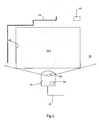
- Fig. 1 schematically shows the structure of an embodiment of a safety laser scanner 10 of a security device according to the invention, in their entirety in Fig. 2 is shown schematically.
- a laser 12 which consists of individual light pulses, is directed via a light deflection unit 16 in a field of view 18 and there remitted by an optionally present object.
- the viewing area 18 comprises the entire opening angle 50 (FIG. Fig. 2
- Remitted light 20 passes back to the laser scanner 10 and is detected there via the deflection unit 16 and by means of a receiving optical system 22 by a receiver 24.
- the light deflecting unit 16 is generally rotatable, with a motor 26 continuously rotating a rotating mirror 28.
- the respective angular position of the rotary mirror 28 is detected by an encoder 30.
- the light beam 14 generated by the laser 12 thus passes over the field of view 18 generated by the rotational movement. If a reflected light signal 20 received by the receiver 24 is received from the field of view 18, the angular position of the deflection unit 30 can be used to determine the angular position of the object in the field of view 18 become.
- the transit time of the individual laser light pulses of the transmitted light 14 is monitored from the emission to the reception of a reflection on the object and closed from the light transit time using the speed of light on the distance of the object from the laser scanner 10. This evaluation takes place in an evaluation unit 32, which is connected to the laser 12, the receiver 24, the motor 26 and encoder 30.
- the location of the object can be determined and in this way, for example, completely monitor two-dimensional monitoring areas 18-1.
- the monitoring area 18-1 is defined in its dimensions by corresponding parameters which are stored in the evaluation unit 32 in a memory 54. If an impermissible object is located in the monitoring area 18-1, the evaluating unit 32 can output a corresponding object detection signal at an output of the laser scanner 10 via a line 33 and thus ultimately output a safety signal, for example to bring about a stop of a dangerous machine ,
- scanners that do not determine the distance based on the light transit time of individual laser pulses, but via triangulation or via a comparison of the phase of amplitude-modulated transmitted light to the phase of the reflected light.
- All said functional components are arranged in a housing 34 which has a front screen 36 at the front, ie in the region of the light exit and light entry.
- the windscreen 36 is to avoid direct reflections in the Receiver set obliquely, so that the angle between the light beam 14 and front screen 36 is not equal to 90 °.
- Fig. 2 shows schematically the safety device according to the invention.
- this includes at least one reference target 45, which may be a single target or else part of a reference contour 44 located outside the monitoring area 18-1, which may consist of house walls or the like.
- the reference contour 44 extends either directly on the surveillance area edge 48 or outside the surveillance area 18-1.
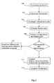
- a transmitted light beam is emitted with the light emitter 12.
- the transmitted light beam 14 is periodically guided through the viewing area 18, so that the surveillance area 18-1, which is part of the viewing area 18, is scanned. If objects are in the field of view 18 of the scanner 10, the transmitted light beam 14 is reflected at these objects and the reflected light is received by the light receiver 24 (step 104).
- Light receiver 24 converts the received light into electrical received signals whose signal levels correspond to the received light intensities. If an impermissible object is located in the monitoring area 18-1, the evaluating unit 32 outputs a safety signal, for example a warning or switch-off signal, on the line 33.
- the external reference target 45 which is detected in step 106 when scanning the field of view 18 from the transmitted light beam 14.
- the actual signal height of the reflections from the reference target 45 is detected (step 108).
- a reference target target signal height is calculated, the minimum target reflectance of the Reference target. This calculation takes place in a reflection degree determination unit 58 and a determination unit 60 of the evaluation unit 32.
- the reference target target signal height is thus the signal height that the scanner must at least see on the reference target in order to enable reliable object recognition.
- the scanner checks in step 112 whether it recognizes at least this reference target target signal height on the reference target for each scan, ie whether the reference target supplies at least the minimum target reflectance. If this is not the case, ie if the reference target / actual signal height detected in step 108 is below the reference target / desired signal level, an error signal is output (step 114).
- the safety device has a well-defined detection capability, even if soft targets, such as fog, rain, snow or other air pollution.
- the scanner's own determination of the minimum target reflectance of the reference target has the further advantage that can serve as a reference target a naturally existing house wall or other objects.
- Fig. 4 A further variant is described in which the actual reflectance of the reference target is repeatedly determined during a normal operation in a step 116 with the reflection degree determination unit 58 and the visibility of the scanner 10 is determined on the basis of this current reflectance in step 118 by a comparison of the actual value.
- Reflectance with the minimum nominal reflectance So that can in an application, for example, the extent of the monitoring area 18-1 can be adjusted depending on the visibility. An application example for this would be collision protection on cranes, for example.
- the scanner 10 could detect a suitable location of the crane if it is permanently within the field of view of the scanner. Depending on the reflectance of this point of the crane then the visibility can be determined and depending on the movement of the crane or the size of the surveillance area for collision avoidance with the crane are adjusted accordingly.
Landscapes
- Engineering & Computer Science (AREA)
- Physics & Mathematics (AREA)
- Computer Networks & Wireless Communication (AREA)
- General Physics & Mathematics (AREA)
- Radar, Positioning & Navigation (AREA)
- Remote Sensing (AREA)
- Electromagnetism (AREA)
- Optical Radar Systems And Details Thereof (AREA)
Claims (9)
- Procédé pour la détection assurée et la détermination de la position d'objets dans une zone de surveillance (18-1) au moyen d'un dispositif de balayage optoélectronique (10) comprenant les étapes consistants à:- Émettre un faisceau de lumière transmis (14) avec un émetteur de lumière (12, 100), et- Balayage périodique de champ de vision (10) du balayage comprenant la zone de surveillance (18-1) avec le faisceau lumineux transmis (14) et par une unité de déflexion (16, 102);- Recevoir le faisceau de lumière transmis réfléchie sur des objets dans le champ de vision avec un récepteur de lumière (24) et fournissant des signaux de réception (20), dont les niveaux des signaux correspondent à les intensités lumineuses reçues (104),- Émettre un signal de sécurité, d'alarme ou d'arrêt, quand un objet non autorisé est détecté dans la zone de surveillance (18-1),
charactérisé par- Fourniture d'une cible de référence externe (45) dans le champ de vision (18, 106),- Déterminer le niveau effectif des réflexions du signal de la cible de référence (45, 108),- Calculer un niveau de consigne du signal de cible de référence (110), ce qui correspond à un pouvoir réflecteur voulu du minimum de la cible de référence (45) à partir de la distance mesurée à la cible de référence (45), d'un caractéristique de réception du récepteur de lumière (24) qui est spécifique du dispositif de balayage et de la distance et du signal de réception mesuré (20) sur la cible de référence (45),- Délivrer un signal d'erreur quand le signal n'atteint pas le niveau du signal de consigne du signal de cible de référence (114) pendant le fonctionnement normal. - Procédé selon l'une des revendications précédentes, dans lequel la réflectance souhaitée minimale de la cible de référence (45) est de 2 % .
- Procédé selon l'une des revendications précédentes, dans lequel le faisceau lumineux transmis (14) comprend des impulsions et le temps de vol de la lumière et de l'angle respectif au cours de laquelle les impulsions de lumière sont transmises sont détectées en dehors du niveau de la réception de signal des signaux (20), et donc la position de la cible de référence (45) est surveillée.
- Procédé selon l'une des revendications précédentes, dans lequel le niveau de consigne du signal de cible de référence est déterminé périodiquement de nouveau, et en référence des paramètres de sécurité, tels que l'étendue de la zone de surveillance (18-1), sont ajustées.
- Procédé selon l'une des revendications précédentes, dans lequel la cible de référence (45) est un objet à contrôler dans la zone de surveillance (18-1).
- Dispositif de sécurité pour un procédé selon l'une quelconque des revendications précédentes, avec un dispositif de balayage opto-électronique (10) comprenant un émetteur de lumière (12) pour émettre un faisceau de lumière transmis (14) avec une unité de déviation (16) pour le balayage périodique d'une champ de vision (18) du dispositif de balayage, y compris (10) de la zone de surveillance (18-1) avec le faisceau lumineux transmis (14), un récepteur de lumière (24) pour recevoir le faisceau réfléchi de lumière transmise (14) d'objets dans la zone de visualisation (18) et pour fournir des signaux de réception (20) qui signalent des niveaux correspondent aux intensités de lumière de réception, une unité d'évaluation (32) pour traiter les signaux de réception et sortir un signal de sécurité, alerte ou un signal d'arrêt, quand un objet non-autorisé est détecté dans la zone de surveillance (18-1) et avec une cible de référence externe (45) dans le champ de vision (18), caractérisé en ce que l'unité d'évaluation (32) comprend:- une unité pour déterminer le niveau de signal (56) pour déterminer le niveau effective de signal de la réflexion à partir de la cible de référence (45),- une unité de détection de facteur de réflexion (58) pour calculer un niveau de la cible de référence (45) de réflexion à partir de la distance mesurée à la cible de référence (45), de la distance de réception de spécification de balayage du récepteur de lumière (24) et à partir au niveau effective du signal de la réflexion de la cible de référence (45),- une unité de détermination (60) pour déterminer un niveau de consigne du signal de cible de référence correspondant au degré de réflexion de consigne minimal de la cible de référence (45) et- une unité de sortie pour délivrer en sortie un signal d'erreur quand le niveau de signal de réception n'atteint pas le niveau de consigne du signal de cible de référence détectée pendant le fonctionnement normal.
- Dispositif de sécurité selon la revendication 6, caractérisé en ce que la cible de référence (45) est constitué d'au moins d'un élément délimitant mécaniquement la zone de surveillance (18-1).
- Dispositif de sécurité selon la revendication 6 ou 7, caractérisé en ce que la cible de référence (45) comprend un rétro-réflecteur.
- Dispositif de sécurité selon l'une quelconque des revendications précédentes 6 à 8, caractérisé en ce que la cible de référence (45) est au moins aussi grande que la résolution géométrique du dispositif de balayage (10).
Priority Applications (1)
| Application Number | Priority Date | Filing Date | Title |
|---|---|---|---|
| EP12174918.8A EP2682780B1 (fr) | 2012-07-04 | 2012-07-04 | Procédé de détection et de détermination de position sécurisée d'objets et dispositif de sécurité |
Applications Claiming Priority (1)
| Application Number | Priority Date | Filing Date | Title |
|---|---|---|---|
| EP12174918.8A EP2682780B1 (fr) | 2012-07-04 | 2012-07-04 | Procédé de détection et de détermination de position sécurisée d'objets et dispositif de sécurité |
Publications (2)
| Publication Number | Publication Date |
|---|---|
| EP2682780A1 EP2682780A1 (fr) | 2014-01-08 |
| EP2682780B1 true EP2682780B1 (fr) | 2014-04-23 |
Family
ID=46395541
Family Applications (1)
| Application Number | Title | Priority Date | Filing Date |
|---|---|---|---|
| EP12174918.8A Active EP2682780B1 (fr) | 2012-07-04 | 2012-07-04 | Procédé de détection et de détermination de position sécurisée d'objets et dispositif de sécurité |
Country Status (1)
| Country | Link |
|---|---|
| EP (1) | EP2682780B1 (fr) |
Families Citing this family (5)
| Publication number | Priority date | Publication date | Assignee | Title |
|---|---|---|---|---|
| DE102016122334A1 (de) * | 2016-11-21 | 2018-05-24 | Pepperl + Fuchs Gmbh | Optische Messvorrichtung zum Überwachen und Erfassen von Objekten in einem Überwachungsbereich |
| DE102017125587A1 (de) | 2017-11-02 | 2019-05-02 | Pepperl + Fuchs Gmbh | Optischer Sensor zum Nachweis von Objekten in einem Erfassungsbereich |
| FR3089736B1 (fr) * | 2018-12-11 | 2020-11-13 | Continental Automotive France | Procédé de détermination de la distance entre un dispositif d’authentification et un véhicule |
| DE102021002904A1 (de) | 2021-06-07 | 2022-05-05 | Daimler Ag | Verfahren zur Ermittlung alterungsbedingter Funktionsbeeinträchtigungen eines Lidarsensors eines Fahrzeugs |
| DE102021214883B4 (de) | 2021-12-22 | 2023-10-12 | Zf Friedrichshafen Ag | Verfahren und System zum Überwachen eines Fahrzeugumfelds |
Citations (5)
| Publication number | Priority date | Publication date | Assignee | Title |
|---|---|---|---|---|
| DE3908273C1 (en) | 1989-03-14 | 1990-05-03 | Fraunhofer-Gesellschaft Zur Foerderung Der Angewandten Forschung Ev, 8000 Muenchen, De | Self-test device for a scanning light probe |
| EP0520247A2 (fr) | 1991-06-15 | 1992-12-30 | Leuze electronic GmbH + Co. | Dispositif de surveillance comportant un émetteur, un récepteur et un circuit d'analyse de signal |
| EP0569686A1 (fr) | 1992-05-09 | 1993-11-18 | Leuze electronic GmbH + Co. | Dispositif de surveillance comportant un émetteur, un récepteur et un circuit d'analyse de signal |
| DE202009004397U1 (de) | 2009-03-28 | 2010-08-12 | Sick Ag | Sicherheitsvorrichtung |
| EP2381268A1 (fr) | 2010-04-22 | 2011-10-26 | Sick AG | Scanner laser de sécurité |
Family Cites Families (5)
| Publication number | Priority date | Publication date | Assignee | Title |
|---|---|---|---|---|
| DE4340756C5 (de) | 1992-12-08 | 2006-08-10 | Sick Ag | Laserabstandsermittlungsvorrichtung |
| DE19607345A1 (de) * | 1996-02-27 | 1997-08-28 | Sick Ag | Laserabstandsermittlungsvorrichtung |
| US5910767A (en) | 1997-07-11 | 1999-06-08 | Laser Guard | Intruder detector system |
| DE19828000C2 (de) | 1998-06-24 | 2000-06-21 | Schmersal Eot Gmbh & Co Kg | Verfahren zur optoelektronischen Überwachung eines Schutzbereichs |
| JP4210662B2 (ja) | 2005-03-17 | 2009-01-21 | 本田技研工業株式会社 | 車両用物体検知装置 |
-
2012
- 2012-07-04 EP EP12174918.8A patent/EP2682780B1/fr active Active
Patent Citations (5)
| Publication number | Priority date | Publication date | Assignee | Title |
|---|---|---|---|---|
| DE3908273C1 (en) | 1989-03-14 | 1990-05-03 | Fraunhofer-Gesellschaft Zur Foerderung Der Angewandten Forschung Ev, 8000 Muenchen, De | Self-test device for a scanning light probe |
| EP0520247A2 (fr) | 1991-06-15 | 1992-12-30 | Leuze electronic GmbH + Co. | Dispositif de surveillance comportant un émetteur, un récepteur et un circuit d'analyse de signal |
| EP0569686A1 (fr) | 1992-05-09 | 1993-11-18 | Leuze electronic GmbH + Co. | Dispositif de surveillance comportant un émetteur, un récepteur et un circuit d'analyse de signal |
| DE202009004397U1 (de) | 2009-03-28 | 2010-08-12 | Sick Ag | Sicherheitsvorrichtung |
| EP2381268A1 (fr) | 2010-04-22 | 2011-10-26 | Sick AG | Scanner laser de sécurité |
Non-Patent Citations (1)
| Title |
|---|
| INTERNATIONAL STANDARD IEC 61496-3, 2008, XP055274673 |
Also Published As
| Publication number | Publication date |
|---|---|
| EP2682780A1 (fr) | 2014-01-08 |
Similar Documents
| Publication | Publication Date | Title |
|---|---|---|
| EP2722684B1 (fr) | Lecteur laser | |
| EP2682780B1 (fr) | Procédé de détection et de détermination de position sécurisée d'objets et dispositif de sécurité | |
| EP3078985B1 (fr) | Capteur optoelectronique et procede de surveillance de transmission d'un disque frontal | |
| EP3435117B1 (fr) | Capteur et procédé de détection et de détermination des distances entre des objets | |
| EP2378309B1 (fr) | Capteur optoélectronique et procédé de production d'informations sur des objets dans une zone de surveillance | |
| DE102011053212B3 (de) | Optoelektronischer Sensor und Verfahren zur Erfassung von Objekten in einem Überwachungsbereich | |
| EP2482094B1 (fr) | Capteur optoélectronique mesurant l'éloignement et procédé de détection d'objet | |
| DE202012010014U1 (de) | Laserscanner | |
| EP3012663B1 (fr) | Systeme de securite destine a securiser l'environnement d'un objet | |
| DE102009034848B4 (de) | Optoelektronischer Sensor | |
| EP2381268B1 (fr) | Scanner laser de sécurité | |
| EP3588139B1 (fr) | Capteur optoélectronique et procédé de détermination de la distance | |
| EP3862780B1 (fr) | Balayeur laser de sécurité et procédé de surveillance de vitre frontale | |
| EP3736607B1 (fr) | Sécurisation de l'environnement d'un véhicule | |
| EP3287809B1 (fr) | Procédé de fonctionnement d'un dispositif de baleyage et dispositif de baleyage | |
| DE102018124837B3 (de) | Sicherheitslaserscanner und Verfahren zum Erhalt der Funktionsfähigkeit | |
| EP3026459B1 (fr) | Systeme de capteur | |
| EP2703837B1 (fr) | Scanner laser de sécurité | |
| DE202010005042U1 (de) | Optoelektronische Vorrichtung | |
| EP2515143A1 (fr) | Procédé de détection et de détermination de position sécurisée d'objets et dispositif de sécurité | |
| EP2637036B1 (fr) | Module complémentaire destiné au montage sur un capteur optique et procédé de fonctionnement d'un capteur optique | |
| EP3527332A1 (fr) | Dispositif capteur de sécurité et procédé de sécurisation d'une machine mobile | |
| DE202012105044U1 (de) | Optoelektronischer Sensor zur Erfassung und Abstandsbestimmung von Objekten | |
| DE202012103344U1 (de) | Sicherheits-Lichtscanner | |
| EP3736605B1 (fr) | Balayeur laser de sécurité et procédé |
Legal Events
| Date | Code | Title | Description |
|---|---|---|---|
| PUAI | Public reference made under article 153(3) epc to a published international application that has entered the european phase |
Free format text: ORIGINAL CODE: 0009012 |
|
| 17P | Request for examination filed |
Effective date: 20130114 |
|
| AK | Designated contracting states |
Kind code of ref document: A1 Designated state(s): AL AT BE BG CH CY CZ DE DK EE ES FI FR GB GR HR HU IE IS IT LI LT LU LV MC MK MT NL NO PL PT RO RS SE SI SK SM TR |
|
| AX | Request for extension of the european patent |
Extension state: BA ME |
|
| GRAP | Despatch of communication of intention to grant a patent |
Free format text: ORIGINAL CODE: EPIDOSNIGR1 |
|
| INTG | Intention to grant announced |
Effective date: 20140211 |
|
| GRAS | Grant fee paid |
Free format text: ORIGINAL CODE: EPIDOSNIGR3 |
|
| GRAA | (expected) grant |
Free format text: ORIGINAL CODE: 0009210 |
|
| AK | Designated contracting states |
Kind code of ref document: B1 Designated state(s): AL AT BE BG CH CY CZ DE DK EE ES FI FR GB GR HR HU IE IS IT LI LT LU LV MC MK MT NL NO PL PT RO RS SE SI SK SM TR |
|
| REG | Reference to a national code |
Ref country code: GB Ref legal event code: FG4D Free format text: NOT ENGLISH |
|
| REG | Reference to a national code |
Ref country code: CH Ref legal event code: EP |
|
| REG | Reference to a national code |
Ref country code: AT Ref legal event code: REF Ref document number: 664148 Country of ref document: AT Kind code of ref document: T Effective date: 20140515 |
|
| REG | Reference to a national code |
Ref country code: IE Ref legal event code: FG4D Free format text: LANGUAGE OF EP DOCUMENT: GERMAN |
|
| REG | Reference to a national code |
Ref country code: DE Ref legal event code: R096 Ref document number: 502012000613 Country of ref document: DE Effective date: 20140528 |
|
| REG | Reference to a national code |
Ref country code: NL Ref legal event code: VDEP Effective date: 20140423 |
|
| REG | Reference to a national code |
Ref country code: LT Ref legal event code: MG4D |
|
| PG25 | Lapsed in a contracting state [announced via postgrant information from national office to epo] |
Ref country code: NL Free format text: LAPSE BECAUSE OF FAILURE TO SUBMIT A TRANSLATION OF THE DESCRIPTION OR TO PAY THE FEE WITHIN THE PRESCRIBED TIME-LIMIT Effective date: 20140423 Ref country code: NO Free format text: LAPSE BECAUSE OF FAILURE TO SUBMIT A TRANSLATION OF THE DESCRIPTION OR TO PAY THE FEE WITHIN THE PRESCRIBED TIME-LIMIT Effective date: 20140723 Ref country code: IS Free format text: LAPSE BECAUSE OF FAILURE TO SUBMIT A TRANSLATION OF THE DESCRIPTION OR TO PAY THE FEE WITHIN THE PRESCRIBED TIME-LIMIT Effective date: 20140823 Ref country code: LT Free format text: LAPSE BECAUSE OF FAILURE TO SUBMIT A TRANSLATION OF THE DESCRIPTION OR TO PAY THE FEE WITHIN THE PRESCRIBED TIME-LIMIT Effective date: 20140423 Ref country code: GR Free format text: LAPSE BECAUSE OF FAILURE TO SUBMIT A TRANSLATION OF THE DESCRIPTION OR TO PAY THE FEE WITHIN THE PRESCRIBED TIME-LIMIT Effective date: 20140724 Ref country code: CY Free format text: LAPSE BECAUSE OF FAILURE TO SUBMIT A TRANSLATION OF THE DESCRIPTION OR TO PAY THE FEE WITHIN THE PRESCRIBED TIME-LIMIT Effective date: 20140423 Ref country code: BG Free format text: LAPSE BECAUSE OF FAILURE TO SUBMIT A TRANSLATION OF THE DESCRIPTION OR TO PAY THE FEE WITHIN THE PRESCRIBED TIME-LIMIT Effective date: 20140723 Ref country code: FI Free format text: LAPSE BECAUSE OF FAILURE TO SUBMIT A TRANSLATION OF THE DESCRIPTION OR TO PAY THE FEE WITHIN THE PRESCRIBED TIME-LIMIT Effective date: 20140423 |
|
| PG25 | Lapsed in a contracting state [announced via postgrant information from national office to epo] |
Ref country code: PL Free format text: LAPSE BECAUSE OF FAILURE TO SUBMIT A TRANSLATION OF THE DESCRIPTION OR TO PAY THE FEE WITHIN THE PRESCRIBED TIME-LIMIT Effective date: 20140423 Ref country code: HR Free format text: LAPSE BECAUSE OF FAILURE TO SUBMIT A TRANSLATION OF THE DESCRIPTION OR TO PAY THE FEE WITHIN THE PRESCRIBED TIME-LIMIT Effective date: 20140423 Ref country code: RS Free format text: LAPSE BECAUSE OF FAILURE TO SUBMIT A TRANSLATION OF THE DESCRIPTION OR TO PAY THE FEE WITHIN THE PRESCRIBED TIME-LIMIT Effective date: 20140423 Ref country code: ES Free format text: LAPSE BECAUSE OF FAILURE TO SUBMIT A TRANSLATION OF THE DESCRIPTION OR TO PAY THE FEE WITHIN THE PRESCRIBED TIME-LIMIT Effective date: 20140423 Ref country code: LV Free format text: LAPSE BECAUSE OF FAILURE TO SUBMIT A TRANSLATION OF THE DESCRIPTION OR TO PAY THE FEE WITHIN THE PRESCRIBED TIME-LIMIT Effective date: 20140423 Ref country code: SE Free format text: LAPSE BECAUSE OF FAILURE TO SUBMIT A TRANSLATION OF THE DESCRIPTION OR TO PAY THE FEE WITHIN THE PRESCRIBED TIME-LIMIT Effective date: 20140423 |
|
| PG25 | Lapsed in a contracting state [announced via postgrant information from national office to epo] |
Ref country code: PT Free format text: LAPSE BECAUSE OF FAILURE TO SUBMIT A TRANSLATION OF THE DESCRIPTION OR TO PAY THE FEE WITHIN THE PRESCRIBED TIME-LIMIT Effective date: 20140825 |
|
| REG | Reference to a national code |
Ref country code: DE Ref legal event code: R026 Ref document number: 502012000613 Country of ref document: DE |
|
| PG25 | Lapsed in a contracting state [announced via postgrant information from national office to epo] |
Ref country code: EE Free format text: LAPSE BECAUSE OF FAILURE TO SUBMIT A TRANSLATION OF THE DESCRIPTION OR TO PAY THE FEE WITHIN THE PRESCRIBED TIME-LIMIT Effective date: 20140423 Ref country code: DK Free format text: LAPSE BECAUSE OF FAILURE TO SUBMIT A TRANSLATION OF THE DESCRIPTION OR TO PAY THE FEE WITHIN THE PRESCRIBED TIME-LIMIT Effective date: 20140423 Ref country code: CZ Free format text: LAPSE BECAUSE OF FAILURE TO SUBMIT A TRANSLATION OF THE DESCRIPTION OR TO PAY THE FEE WITHIN THE PRESCRIBED TIME-LIMIT Effective date: 20140423 Ref country code: SK Free format text: LAPSE BECAUSE OF FAILURE TO SUBMIT A TRANSLATION OF THE DESCRIPTION OR TO PAY THE FEE WITHIN THE PRESCRIBED TIME-LIMIT Effective date: 20140423 Ref country code: RO Free format text: LAPSE BECAUSE OF FAILURE TO SUBMIT A TRANSLATION OF THE DESCRIPTION OR TO PAY THE FEE WITHIN THE PRESCRIBED TIME-LIMIT Effective date: 20140423 |
|
| PLBI | Opposition filed |
Free format text: ORIGINAL CODE: 0009260 |
|
| PG25 | Lapsed in a contracting state [announced via postgrant information from national office to epo] |
Ref country code: LU Free format text: LAPSE BECAUSE OF FAILURE TO SUBMIT A TRANSLATION OF THE DESCRIPTION OR TO PAY THE FEE WITHIN THE PRESCRIBED TIME-LIMIT Effective date: 20140704 |
|
| PLAX | Notice of opposition and request to file observation + time limit sent |
Free format text: ORIGINAL CODE: EPIDOSNOBS2 |
|
| 26 | Opposition filed |
Opponent name: PEPPERL + FUCHS GMBH Effective date: 20150123 |
|
| PG25 | Lapsed in a contracting state [announced via postgrant information from national office to epo] |
Ref country code: IT Free format text: LAPSE BECAUSE OF FAILURE TO SUBMIT A TRANSLATION OF THE DESCRIPTION OR TO PAY THE FEE WITHIN THE PRESCRIBED TIME-LIMIT Effective date: 20140423 |
|
| REG | Reference to a national code |
Ref country code: IE Ref legal event code: MM4A |
|
| REG | Reference to a national code |
Ref country code: DE Ref legal event code: R026 Ref document number: 502012000613 Country of ref document: DE Effective date: 20150123 |
|
| PLBB | Reply of patent proprietor to notice(s) of opposition received |
Free format text: ORIGINAL CODE: EPIDOSNOBS3 |
|
| PG25 | Lapsed in a contracting state [announced via postgrant information from national office to epo] |
Ref country code: SI Free format text: LAPSE BECAUSE OF FAILURE TO SUBMIT A TRANSLATION OF THE DESCRIPTION OR TO PAY THE FEE WITHIN THE PRESCRIBED TIME-LIMIT Effective date: 20140423 |
|
| PG25 | Lapsed in a contracting state [announced via postgrant information from national office to epo] |
Ref country code: IE Free format text: LAPSE BECAUSE OF NON-PAYMENT OF DUE FEES Effective date: 20140704 |
|
| PG25 | Lapsed in a contracting state [announced via postgrant information from national office to epo] |
Ref country code: MC Free format text: LAPSE BECAUSE OF FAILURE TO SUBMIT A TRANSLATION OF THE DESCRIPTION OR TO PAY THE FEE WITHIN THE PRESCRIBED TIME-LIMIT Effective date: 20140423 Ref country code: SM Free format text: LAPSE BECAUSE OF FAILURE TO SUBMIT A TRANSLATION OF THE DESCRIPTION OR TO PAY THE FEE WITHIN THE PRESCRIBED TIME-LIMIT Effective date: 20140423 |
|
| PG25 | Lapsed in a contracting state [announced via postgrant information from national office to epo] |
Ref country code: MT Free format text: LAPSE BECAUSE OF FAILURE TO SUBMIT A TRANSLATION OF THE DESCRIPTION OR TO PAY THE FEE WITHIN THE PRESCRIBED TIME-LIMIT Effective date: 20140423 |
|
| REG | Reference to a national code |
Ref country code: FR Ref legal event code: PLFP Year of fee payment: 5 |
|
| PG25 | Lapsed in a contracting state [announced via postgrant information from national office to epo] |
Ref country code: HU Free format text: LAPSE BECAUSE OF FAILURE TO SUBMIT A TRANSLATION OF THE DESCRIPTION OR TO PAY THE FEE WITHIN THE PRESCRIBED TIME-LIMIT; INVALID AB INITIO Effective date: 20120704 Ref country code: BE Free format text: LAPSE BECAUSE OF FAILURE TO SUBMIT A TRANSLATION OF THE DESCRIPTION OR TO PAY THE FEE WITHIN THE PRESCRIBED TIME-LIMIT Effective date: 20140731 |
|
| REG | Reference to a national code |
Ref country code: DE Ref legal event code: R100 Ref document number: 502012000613 Country of ref document: DE |
|
| PLCK | Communication despatched that opposition was rejected |
Free format text: ORIGINAL CODE: EPIDOSNREJ1 |
|
| PLBN | Opposition rejected |
Free format text: ORIGINAL CODE: 0009273 |
|
| STAA | Information on the status of an ep patent application or granted ep patent |
Free format text: STATUS: OPPOSITION REJECTED |
|
| 27O | Opposition rejected |
Effective date: 20161130 |
|
| REG | Reference to a national code |
Ref country code: FR Ref legal event code: PLFP Year of fee payment: 6 |
|
| PG25 | Lapsed in a contracting state [announced via postgrant information from national office to epo] |
Ref country code: TR Free format text: LAPSE BECAUSE OF FAILURE TO SUBMIT A TRANSLATION OF THE DESCRIPTION OR TO PAY THE FEE WITHIN THE PRESCRIBED TIME-LIMIT Effective date: 20140423 |
|
| PG25 | Lapsed in a contracting state [announced via postgrant information from national office to epo] |
Ref country code: MK Free format text: LAPSE BECAUSE OF FAILURE TO SUBMIT A TRANSLATION OF THE DESCRIPTION OR TO PAY THE FEE WITHIN THE PRESCRIBED TIME-LIMIT Effective date: 20140423 |
|
| REG | Reference to a national code |
Ref country code: FR Ref legal event code: PLFP Year of fee payment: 7 |
|
| REG | Reference to a national code |
Ref country code: AT Ref legal event code: MM01 Ref document number: 664148 Country of ref document: AT Kind code of ref document: T Effective date: 20170704 |
|
| PG25 | Lapsed in a contracting state [announced via postgrant information from national office to epo] |
Ref country code: AL Free format text: LAPSE BECAUSE OF FAILURE TO SUBMIT A TRANSLATION OF THE DESCRIPTION OR TO PAY THE FEE WITHIN THE PRESCRIBED TIME-LIMIT Effective date: 20140423 |
|
| PG25 | Lapsed in a contracting state [announced via postgrant information from national office to epo] |
Ref country code: AT Free format text: LAPSE BECAUSE OF NON-PAYMENT OF DUE FEES Effective date: 20170704 |
|
| PGFP | Annual fee paid to national office [announced via postgrant information from national office to epo] |
Ref country code: CH Payment date: 20190725 Year of fee payment: 8 |
|
| PGFP | Annual fee paid to national office [announced via postgrant information from national office to epo] |
Ref country code: FR Payment date: 20200727 Year of fee payment: 9 Ref country code: GB Payment date: 20200724 Year of fee payment: 9 |
|
| REG | Reference to a national code |
Ref country code: CH Ref legal event code: PL |
|
| PG25 | Lapsed in a contracting state [announced via postgrant information from national office to epo] |
Ref country code: LI Free format text: LAPSE BECAUSE OF NON-PAYMENT OF DUE FEES Effective date: 20200731 Ref country code: CH Free format text: LAPSE BECAUSE OF NON-PAYMENT OF DUE FEES Effective date: 20200731 |
|
| GBPC | Gb: european patent ceased through non-payment of renewal fee |
Effective date: 20210704 |
|
| PG25 | Lapsed in a contracting state [announced via postgrant information from national office to epo] |
Ref country code: GB Free format text: LAPSE BECAUSE OF NON-PAYMENT OF DUE FEES Effective date: 20210704 |
|
| PG25 | Lapsed in a contracting state [announced via postgrant information from national office to epo] |
Ref country code: FR Free format text: LAPSE BECAUSE OF NON-PAYMENT OF DUE FEES Effective date: 20210731 |
|
| PGFP | Annual fee paid to national office [announced via postgrant information from national office to epo] |
Ref country code: DE Payment date: 20230720 Year of fee payment: 12 |