EP2682622A1 - Thermal processing method, outer connecting member, and tripod-type constant velocity universal joint - Google Patents
Thermal processing method, outer connecting member, and tripod-type constant velocity universal joint Download PDFInfo
- Publication number
- EP2682622A1 EP2682622A1 EP12752929.5A EP12752929A EP2682622A1 EP 2682622 A1 EP2682622 A1 EP 2682622A1 EP 12752929 A EP12752929 A EP 12752929A EP 2682622 A1 EP2682622 A1 EP 2682622A1
- Authority
- EP
- European Patent Office
- Prior art keywords
- joint member
- outer joint
- roller
- portions
- guide surfaces
- Prior art date
- Legal status (The legal status is an assumption and is not a legal conclusion. Google has not performed a legal analysis and makes no representation as to the accuracy of the status listed.)
- Granted
Links
Images



Classifications
-
- F—MECHANICAL ENGINEERING; LIGHTING; HEATING; WEAPONS; BLASTING
- F16—ENGINEERING ELEMENTS AND UNITS; GENERAL MEASURES FOR PRODUCING AND MAINTAINING EFFECTIVE FUNCTIONING OF MACHINES OR INSTALLATIONS; THERMAL INSULATION IN GENERAL
- F16D—COUPLINGS FOR TRANSMITTING ROTATION; CLUTCHES; BRAKES
- F16D3/00—Yielding couplings, i.e. with means permitting movement between the connected parts during the drive
- F16D3/16—Universal joints in which flexibility is produced by means of pivots or sliding or rolling connecting parts
- F16D3/20—Universal joints in which flexibility is produced by means of pivots or sliding or rolling connecting parts one coupling part entering a sleeve of the other coupling part and connected thereto by sliding or rolling members
- F16D3/202—Universal joints in which flexibility is produced by means of pivots or sliding or rolling connecting parts one coupling part entering a sleeve of the other coupling part and connected thereto by sliding or rolling members one coupling part having radially projecting pins, e.g. tripod joints
-
- F—MECHANICAL ENGINEERING; LIGHTING; HEATING; WEAPONS; BLASTING
- F16—ENGINEERING ELEMENTS AND UNITS; GENERAL MEASURES FOR PRODUCING AND MAINTAINING EFFECTIVE FUNCTIONING OF MACHINES OR INSTALLATIONS; THERMAL INSULATION IN GENERAL
- F16D—COUPLINGS FOR TRANSMITTING ROTATION; CLUTCHES; BRAKES
- F16D3/00—Yielding couplings, i.e. with means permitting movement between the connected parts during the drive
- F16D3/16—Universal joints in which flexibility is produced by means of pivots or sliding or rolling connecting parts
- F16D3/20—Universal joints in which flexibility is produced by means of pivots or sliding or rolling connecting parts one coupling part entering a sleeve of the other coupling part and connected thereto by sliding or rolling members
- F16D3/202—Universal joints in which flexibility is produced by means of pivots or sliding or rolling connecting parts one coupling part entering a sleeve of the other coupling part and connected thereto by sliding or rolling members one coupling part having radially projecting pins, e.g. tripod joints
- F16D3/205—Universal joints in which flexibility is produced by means of pivots or sliding or rolling connecting parts one coupling part entering a sleeve of the other coupling part and connected thereto by sliding or rolling members one coupling part having radially projecting pins, e.g. tripod joints the pins extending radially outwardly from the coupling part
- F16D3/2055—Universal joints in which flexibility is produced by means of pivots or sliding or rolling connecting parts one coupling part entering a sleeve of the other coupling part and connected thereto by sliding or rolling members one coupling part having radially projecting pins, e.g. tripod joints the pins extending radially outwardly from the coupling part having three pins, i.e. true tripod joints
-
- F—MECHANICAL ENGINEERING; LIGHTING; HEATING; WEAPONS; BLASTING
- F16—ENGINEERING ELEMENTS AND UNITS; GENERAL MEASURES FOR PRODUCING AND MAINTAINING EFFECTIVE FUNCTIONING OF MACHINES OR INSTALLATIONS; THERMAL INSULATION IN GENERAL
- F16D—COUPLINGS FOR TRANSMITTING ROTATION; CLUTCHES; BRAKES
- F16D2250/00—Manufacturing; Assembly
- F16D2250/0038—Surface treatment
- F16D2250/0053—Hardening
-
- F—MECHANICAL ENGINEERING; LIGHTING; HEATING; WEAPONS; BLASTING
- F16—ENGINEERING ELEMENTS AND UNITS; GENERAL MEASURES FOR PRODUCING AND MAINTAINING EFFECTIVE FUNCTIONING OF MACHINES OR INSTALLATIONS; THERMAL INSULATION IN GENERAL
- F16D—COUPLINGS FOR TRANSMITTING ROTATION; CLUTCHES; BRAKES
- F16D2300/00—Special features for couplings or clutches
- F16D2300/10—Surface characteristics; Details related to material surfaces
Definitions
- the present invention relates to a heat treatment method, an outer joint member, and a tripod type constant velocity universal joint.
- the tripod type constant velocity universal joint As a constant velocity universal joint used in a power transmission device of an automobile, various industrial machines, or the like, there is a tripod type constant velocity universal joint using a tripod member as an inner joint member.
- the tripod type constant velocity universal joint includes, for example, as illustrated in Fig. 15 , an outer joint member 1, a tripod member 2 serving as the inner joint member, and torque transmission members (roller members) 3.
- the outer joint member 1 includes a cup-like mouth portion 4 opened at one end thereof.
- a cup-like mouth portion 4 opened at one end thereof.
- three track grooves 6 extending in an axial direction of the outer joint member.
- roller guide surfaces (roller sliding surfaces) 7a, 7a In side walls facing to each other in a circumferential direction of each of track grooves 6, there are formed roller guide surfaces (roller sliding surfaces) 7a, 7a.
- the tripod member 2 includes a boss 8 and leg shafts 9.
- the boss 8 is provided with spline hole or serration hole 11 which is coupled to a shaft (not shown) to be allowed to transmit torque.
- the leg shafts 9 each protrude in a radial direction from positions trisecting the boss 8 in the circumferential direction.
- each of the torque transmission members 3 includes: a roller 12 including a ring-like body including a radially-outer surface 13 formed into a convex spherical surface; and a ring 15 fitted into the roller 12 through intermediation of a plurality of rollers 16. That is, the roller 12 and the ring 15 are unitized through intermediation of the plurality of rollers 16.
- Those members and the like constitute a roller assembly.
- the roller 12 can be called an outer roller
- the ring 15 can be called an inner roller.
- the outer joint member 1 includes: the mouth portion 4 including the track grooves 6; and a stem portion (not shown) provided to protrude from a bottom wall of the mouth portion 4. Further, a radially-inner surface of the mouth portion 4 exhibits a shape of a three-petal corolla of a flower, in which smaller radially-inner portions 7b and larger radially-inner portions 7c are alternately connected together through intermediation of the roller guide surfaces 7a in the circumferential direction.
- the roller guide surfaces 7a facing to each other in the circumferential direction and the track grooves 6 including the larger radially-inner portions 7c each provided between both of the roller guide surfaces 7a, 7a are formed at three positions in an inner periphery of the outer joint member.
- the tripod type constant velocity universal joint illustrated in Fig. 15 uses so-called double-roller type roller members each including the inner roller and the outer roller.
- the tripod type constant velocity universal joint may use so-called single-roller type roller members each including a roller fitted onto a cylindrical outer peripheral surface of the leg shaft through a plurality of needle rollers in such a manner that the roller is rotatable.
- each of the leg shafts 9 includes a cylindrical outer peripheral surface 74, and an annular ring groove 76 formed in vicinity of an end of each of the leg shafts.
- a roller 80 is fitted onto an outer periphery of each of the leg shaft 9 through a plurality of needle rollers 82 in such a manner that the roller 80 is rotatable.
- the cylindrical outer peripheral surface 74 of each of the leg shafts 9 provides an inner raceway surface for the plurality of needle rollers 82.
- the roller 80 includes a cylindrical inner peripheral surface to provide an outer raceway surface for the plurality of needle rollers 82.
- the plurality of needle rollers 82 are held in contact with an outer washer 84 on outer end surfaces of the plurality of needle rollers, and with an inner washer 88 on end surfaces opposite to the outer end surfaces of the plurality of needle rollers, when viewed from a radial direction of the leg shaft 9.
- the outer washer 84 is regulated from moving in the axial direction by a circlip 86 mounted into the ring groove 76.
- the plurality of needle rollers 82 are also regulated from moving in the axial direction.
- the roller guide surfaces 7a of the outer joint member 1 are subjected to heat hardening treatment.
- heat hardening treatment there is induction quenching.
- the induction quenching is mainly divided into a one-shot quenching method of performing heat treatment at a fixed position (Patent Literature 1), and a mobile quenching method in which the coil is moved relative to the outer joint member (Patent Literature 2).
- a high-frequency heating apparatus including a high-frequency induction heating coil 17.
- the high-frequency induction heating coil 17 includes heating portions 17a, 17a, 17a respectively fitted into the three track grooves 6 of the outer joint member 1. Therefore, it is possible to both heat and rapidly cool the roller guide surfaces 7a over an axial entire region of the joint at one time.
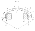
- Patent Literature 1 described above in order to prevent hardened layers from being formed in inner surfaces of the larger radially-inner portions 7c, non-conductive ferrite cores are fitted in an induction coil. Therefore, by using the above-mentioned high-frequency induction heating apparatus, there are formed hardened layers S only in surface layers of the roller guide surfaces 7a as illustrated in Fig. 11 .
- the high-frequency induction heating apparatus includes: a coil 18 wound to have a three-leaf clover shape; and a cooling jacket 19 attached to the coil 18.
- the coil 18 includes heating portions 18a, 18a, 18a each having substantially triangle shape and being provided at about 120° pitches in a circumferential direction of the coil.
- Each of the heating portions 18a includes: curved portions 20a, 20a respectively opposed to the roller guide surfaces 7a; and a straight portion 20b opposed to the larger radially-inner portion 7c.
- the cooling jacket 19 has a three-leaf clover shape similarly to the coil 18.
- the coil 18 and the cooling jacket 19 are moved along an axial direction in the mouth portion 4 of the outer joint member 1.
- heated surfaces roll guide surfaces 7a and larger radially-inner portions 7c
- the heated surfaces are rapidly cooled with cooling water injected through the cooling jacket 19.
- the roller guide surfaces 7a and the larger radially-inner portions 7c are subjected to the heat hardening treatment. In this manner, the hardened layers S are formed.
- the mobile quenching has effects of stabilizing occurring distortion, uniforming a thickness of the quenched and hardened layer, and the like.
- a boot band fastening groove 5 is formed, and a portion in which the boot band fastening groove 5 is provided is thin. Therefore, the hardened layers S in the thin-walled portion may give way to a side of the outer periphery.
- the above-mentioned portion may be weaken in terms of a strength thereof. Therefore, there is a demerit in that a degree of freedom for designing is limited, for example a downsizing of the joint becomes difficult.
- the present invention has been made in view of the above-mentioned circumstances, and it is an object of the present invention to provide a heat treatment method capable of molding, by mobile quenching of induction quenching, an outer joint member of a tripod type constant velocity universal joint excellent in a strength thereof without forming hardened layers in larger radially-inner portions, and to provide the outer joint member and the tripod type constant velocity universal joint which are manufactured by the above-mentioned heat treatment method.
- a heat treatment method for forming hardened layers in roller guide surfaces of an outer joint member including: performing mobile quenching in such a manner that a high-frequency induction heating coil is moved in an axial direction relative to the outer joint member including track grooves which are formed at three positions of an inner periphery of the outer joint member, and each of which includes: the roller guide surfaces facing to each other in a circumferential direction of the outer joint member; and a larger radially-inner portion provided between both of the roller guide surfaces; providing heating-suppressing portions for the larger radially-inner portions in positions of the high-frequency induction heating coil, the positions being respectively opposed to the larger radially-inner portions; and setting a range corresponding to a boot mounting portion in at least a center portion in the circumferential direction in each of the larger radially-inner portions of the outer joint member to be an unquenched portion by cutting out the magnetic field lines with the magnetic field line cut-out bodies.
- the heat treatment method it is possible to form the hardened layers in the roller guide surfaces by the mobile quenching of induction quenching without forming the hardened layer in the range corresponding to the boot mounting portion in at least the center portion in the circumferential direction in each of the larger radially-inner portions of the outer joint member.
- the heating-suppressing portions for the larger radially-inner portions include magnetic field line cut-out bodies for cutting out magnetic field lines generated through the high-frequency induction heating coil.
- the magnetic field line cut-out bodies include, for example, ferromagnetic cores fitted into portions of the high-frequency induction heating coil, at which the ferromagnetic cores come close to the larger radially-inner portions, respectively.
- each of the ferromagnetic cores includes, for example, a silicon steel.
- a heat treatment method for forming hardened layers in roller guide surfaces of an outer joint member including: performing mobile quenching in such a manner that a high-frequency induction heating coil is moved in an axial direction relative to the outer joint member including track grooves which are formed at three positions of an inner periphery of the outer joint member, and each of which includes: the roller guide surfaces facing to each other in a circumferential direction of the outer joint member; and a larger radially-inner portion provided between both of the roller guide surfaces; and setting a range corresponding to a boot mounting portion in at least a center portion in the circumferential direction in each of the larger radially-inner portions of the outer joint member to be an unquenched portion by the high-frequency induction heating coil including retracted portions to be prevented from coming close to the larger radially-inner portions.
- the high-frequency induction heating coil includes the retracted positions to be prevented from coming close to the larger radially-inner portions. Therefore, the range corresponding to the boot mounting portion in at least the center portion in the circumferential direction in each of the larger radially-inner portions is prevented from being heated by the heat treatment, and the range becomes the unquenched portion.
- a heat treatment method for forming hardened layers in roller guide surfaces of an outer joint member including: performing mobile quenching in such a manner that a high-frequency induction heating coil is moved in an axial direction relative to the outer joint member including track grooves which are formed at three positions of an inner periphery of the outer joint member, and each of which includes: the roller guide surfaces facing to each other in a circumferential direction of the outer joint member; and a larger radially-inner portion provided between both of the roller guide surfaces; providing, on an outer diameter side of the roller guide surfaces of the outer joint member, flange portions opposed to a roller member; and setting at least a range corresponding to a boot mounting portion in each of the larger radially-inner portions to be an unquenched portion serving as an unheated portion.
- the flange portions opposed to the roller member are provided on an outer diameter side of the roller guide surfaces of the outer joint member. Therefore, at least the range corresponding to the boot mounting portion in each of the larger radially-inner portions is prevented from being heated by the heat treatment, and the range becomes the unquenched portion.
- Each of the heat treatment methods may include: forming a smaller radially-inner portion between the larger radially-inner portions of the outer joint member; and forming a hardened layer in the smaller radially-inner portion by the mobile quenching. Further, each of the heat treatment methods may further include setting an entire of each of the larger radially-inner portions of the outer joint member to be an unquenched portion.
- a tripod type constant velocity universal joint includes: the outer joint member treated by the heat treatment method; a tripod member including three leg shafts arranged in the outer joint member and protruded in a radial direction; and a roller member mounted to each of the three leg shafts of the tripod member and guided in an axial direction of the outer joint member along the roller guide surfaces.
- the roller member is fitted into a spherical outer peripheral surface of each of the three leg shafts to be capable of oscillating, and is guided in the axial direction of the outer joint member along the roller guide surfaces.
- the roller member may include: a roller inserted in each of track grooves of the outer joint member; and a ring fitted onto each of the three leg shafts, for supporting the roller to be rotatable.
- the roller may be movable in the axial direction of the outer joint member along the roller guide surfaces, and an inner peripheral surface of the ring may be formed to have a circular-arc convex cross-section.
- an outer peripheral surface of each of the three leg shafts may be formed to have a straight shape in a longitudinal section of each of the three leg shafts and to be held, in a cross-section of each of the three leg shafts, in contact with the inner peripheral surface of the ring in a direction orthogonal to an axis of the tripod type constant velocity universal joint and form a gap with respect to the inner peripheral surface of the ring in an axial direction of the tripod type constant velocity universal joint.
- each of the three leg shafts be set to have a substantially oval shape including a longitudinal axis orthogonal to the axis of the tripod type constant velocity universal joint.
- the hardened layers can be formed in the roller guide surfaces without forming the hardened layer in the range corresponding to the boot mounting portion of at least the center portion in the circumferential direction in each of the larger radially-inner portions of the outer joint member. Therefore, it is possible to ensure a strength of the opening portion of the outer joint member.
- the mobile quenching is employed as a quenching method, and hence distortion is difficult to occur, and a thickness of the quenched and hardened layers can be uniformed.
- each of the ferromagnetic core may include, for example, a silicon steel. In this case, without using a specific (special) material, it is possible to attach the ferromagnetic cores to the high-frequency induction heating coil at relatively low cost.
- the unquenched portions may be formed in the entire larger radially-inner portions of the outer joint member, or the unquenched portions may be prevented from being formed on the joint deep side of the larger radially-inner portions. Otherwise, the hardened layers may be formed only in the roller guide surfaces. Even in this case, without deteriorating a function as the outer joint member, it is possible to form the hardened layers in an optimum range.
- the outer joint member of the tripod type constant velocity universal joint of the present invention is treated by the heat treatment method. Therefore, the outer joint member is stable in terms of a strength thereof and is excellent in durability.
- the tripod type constant velocity universal joint of the present invention uses the outer joint member treated by the heat treatment method, and hence becomes a high-quality tripod type constant velocity universal joint excellent in the durability. In addition, a degree of freedom for designing, for example, downsizing of the joint increases. Further, the outer joint member is applicable to various types of tripod type constant velocity universal joints.
- Fig. 1 illustrates a main part sectional view of an outer joint member subjected to heat hardening treatment by a heat treatment method according to the present invention.
- the outer joint member is used in a tripod type constant velocity universal joint as illustrated in Fig. 4 to Fig. 6 .
- the tripod type constant velocity universal joint includes: an outer joint member 21; a tripod member 22 serving as an inner joint member; and torque transmission members 23.
- the outer joint member 21 includes: a cup-like mouth portion 24 opened at one end thereof; and track grooves 26 each extending in an axial direction from positions trisecting an inner periphery thereof in the circumferential direction.
- the mouth portion 24 has a non-cylindrical shape in which larger-diameter portions 24a and smaller-diameter portions 24b are alternately arranged when viewed in a cross-section. That is, the mouth portion 24 forms the larger-diameter portions 24a and the smaller-diameter portions 24b.
- the three track grooves 26 each extending in the axial direction.
- roller guide surfaces In side walls facing to each other in the circumferential direction of each of track grooves 26, there are formed roller guide surfaces (roller sliding surfaces) 27, 27. Further, a radially-inner surface exhibits a shape of a three-petal corolla of a flower, in which smaller radially-inner portions 45 and larger radially-inner portions 46 are alternately connected together through intermediation of the roller guide surfaces 27 in the circumferential direction. That is, in the outer joint member 21, the roller guide surfaces 27 and track grooves 6 are formed at three positions in an inner periphery of the outer joint member. In this case, the roller guide surfaces 27 face to each other in the circumferential direction, and the track grooves 6 include the larger radially-inner portions 46 each provided between both of the roller guide surfaces 27, 27.
- the tripod member 22 includes a boss 28 and leg shafts 29.
- the boss 28 is provided with a spline hole or a serration hole 31 which is coupled to a shaft (not shown) to be allowed to transmit torque.
- the leg shafts 29 each protrude in a radial direction from positions trisecting the boss 28 in the circumferential direction.
- each of the torque transmission members (roller members) 23 includes: a roller 32 including a ring-like body including a radially-outer surface 33 formed into a convex spherical surface; and a ring 35 fitted into the roller 32 through intermediation of a plurality of rollers 36. That is, the roller 32 and the ring 35 are unitized through intermediation of the plurality of rollers 36.
- Those members and the like constitute a roller assembly (roller member).
- the roller 32 can be called an outer roller
- the ring 35 can be called an inner roller.
- the ring (inner roller) 35 is fitted onto an outer peripheral surface of the leg shaft 29.
- a cylindrical outer peripheral surface of the inner roller 35 is used as an inner raceway surface
- a cylindrical inner peripheral surface of the outer roller 32 is used as an outer raceway surface.
- the needle rollers 36 are interposed to be rotatable.
- the needle rollers 36 are incorporated under a so-called full state, in which a large number of the rollers are provided as much as possible and a retainer is not used.
- washers 37 for detachment of the needle rollers 36.
- a radially-inner surface of the ring 35 is formed into a circular-arc convex surface.
- a radially-outer surface of the leg shaft 29 is set to have a straight shape in a longitudinal section.
- the radially-outer surface of the leg shaft 29 is set, in a cross-section, as illustrated in Fig. 5 and Fig. 6 , to be held in contact with the radially-inner surface of the ring 35 in a direction orthogonal to an axis of the joint and to form gaps 40 with respect to the radially-inner surface of the ring 35 in the axial direction of the joint. That is, the cross-section of the leg shaft 29 is set to have a substantially oval shape including a longitudinal axis orthogonal to the axis of the joint.
- an opening portion of the outer joint member 21 is sealed with a boot (not shown).
- the boot includes a larger-diameter portion, a smaller-diameter portion, and a bellows portion coupling the larger-diameter portion and the smaller-diameter portion.
- a boot mounting portion 44 including a recess groove 43 as illustrated in Fig. 5 .
- the boot mounting portion 44 is fitted onto the larger-diameter portion of the boot, and the larger-diameter portion is fastened with the boot band. In this manner, the larger-diameter portion of the boot is mounted onto the boot mounting portion 44 of the outer joint member 21.
- the shaft is coupled to the tripod member 22.
- a boot mounting portion including a recess groove is formed also in the shaft. The boot mounting portion of the shaft is fitted onto the smaller-diameter portion of the boot, and the smaller-diameter portion is fastened with the boot band. In this manner, the smaller-diameter portion of the boot is mounted onto the boot mounting portion of the shaft.
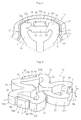
- a high-frequency heating apparatus 52 including a high-frequency induction heating coil 51 illustrated in Fig. 2 and Fig. 3 .
- the high-frequency induction heating coil 51 includes three heating portions 51A, 51B, 51C having substantially triangular shapes, which are arranged to have a three-leaf clover shape.
- Each of the heating portions 51A, 51B, 51C includes: curved portions 53, 53 to face with respect to the roller guide surfaces 27; and straight portions 54 to face to the larger radially-inner portions 46.
- heating-suppressing portions for the larger radially-inner portions 46 are provided in positions of the high-frequency induction heating coil 56, the positions being respectively opposed to the larger radially-inner portions 46.
- the heating-suppressing portions include magnetic field line cut-out bodies A.
- a recessed portion 55 is provided in a center portion of a surface of each of the straight portions 54, the surface being opposed to each of the larger radially-inner portions.
- the magnetic field line cut-out body A including the ferromagnetic core 56 is arranged.
- a longitudinal length L of the ferromagnetic core 56 is set to be smaller than a longitudinal length L1 of the recessed portion 55.
- a lateral length W of the ferromagnetic core 56 is set to be substantially the same as a lateral length W1 of the recessed portion 55. Therefore, upper surfaces of the heating portions 51A, 51B, 51C and upper surfaces of the ferromagnetic core 56 are arranged to be flush with each other. Lower surfaces of the heating portions 51A, 51B, 51C and lower surfaces of the ferromagnetic core 56 are arranged to be flush with each other. Further, between side surfaces of the recessed portion 55 and corresponding side surfaces of the ferromagnetic core 56, there are respectively formed gaps 60. Note that, a thickness dimension T of the ferromagnetic core 56 is set to be larger than a depth dimension T1 of the recessed portion 55.
- An outer surface 56a of the ferromagnetic core 56 protrudes slightly to a side of the larger radially-inner portion with respect to an outer surface (surface opposed to the larger radially-inner portion) 54a of the straight line 54 of the heating portion 51A (51B, 51C).
- a cooling jacket as illustrated in Fig. 12 or the like is attached to a lower portion of the high-frequency induction heating coil 51.
- the cooling jacket includes a cooling piping in which cooling water flows, and has a shape substantially corresponding to a shape of the high-frequency induction heating coil 51.
- the high-frequency induction heating coil 51 is supplied with high-frequency current from a high-frequency power source (not shown). In this case, the high-frequency current flows through the heating portion 51A, the heating portion 51B, and the heating portion 51C in this order. As described above, when the high-frequency current flows, an induced electromotive force is generated due to an electromagnetic induction effect. Due to the electromagnetic induction effect, Joule heat is generated. As a result, the roller guide surfaces 27 and the like of the outer joint member 21 can be heated.
- the high-frequency induction heating coil 51 is continuously moved from a side of an opening portion of the mouth portion to a deep side of the mouth portion. In this manner, the roller guide surfaces 27 and the like are heated from the side of the opening portion to the deep side. Further, along with the above-mentioned movement of the high-frequency induction heating coil 51, the cooling jacket is moved. Thus, a cooling fluid (cooling water) is injected from the cooling jacket to a heated portion of the outer joint member 21, to thereby cool the heated portion. That is, correspondingly to a relative movement of the high-frequency induction heating coil 51, the roller guide surfaces 27 and the like are subsequently heated. Then, following the above-mentioned heating operation, the heated portion is rapidly cooled with the cooling fluid. In this way, induction quenching is performed.
- a cooling fluid cooling water
- the ferromagnetic core 56 cuts out magnetic field lines generated through the high-frequency induction heating coil 51. That is, the ferromagnetic core is made of amaterial having high magnetic permeability and is provided to the coil, and hence the ferromagnetic core has an effect of amplifying power through concentrating the magnetic field lines to a work. At the same time, the ferromagnetic core is used for cutting out the magnetic field lines and for preventing undesired heating.
- the unquenched portions 50 can be formed in the larger radially-inner portions 46. That cannot be performed by conventional mobile quenching. Therefore, as illustrated in Fig. 1 , in each of the larger radially-inner portions 46 to which the ferromagnetic core 56 faces, the unquenched portion 50 in which the hardened layers S are prevented from being formed is formed.
- the hardened layers S can be formed in the roller guide surfaces 27, 27. Therefore, it is possible to ensure a strength of the opening portion of the outer joint member 21.
- the mobile quenching is employed as a quenching method, and hence distortion is difficult to occur, and a thickness of the quenched and hardened layers can be uniformed.
- the magnetic field line cut-out bodies A include the ferromagnetic cores 56, it is possible to stably form the unquenched portions 50.
- the ferromagnetic cores 56 may includes, for example, a silicon steel. In this case, without using a specific (special) material, it is possible to attach the ferromagnetic cores 56 to the high-frequency induction heating coil 51 at relatively low cost.
- the outer joint member 21 in which the hardened layers S are formed is treated by the heat treatment method. Therefore, the outer joint member 21 is stable in terms of a strength thereof and is excellent in durability. Further, the outer joint member 21 molded in the above-mentioned manner can be used for assembling the tripod type constant velocity universal joint as illustrated in Fig. 4 to Fig. 6 or the like. Therefore, the tripod type constant velocity universal joint uses the outer j oint member treated by the heat treatment method, and hence becomes a high-quality tripod type constant velocity universal joint excellent in the durability. In addition, a degree of freedom for designing, for example, downsizing of the joint increases.
- each of the torque transmission members (roller members) 23 is allowed to be tilted in the track groove 26.
- tilting of the roller is capable of absorbing tilting of the leg shaft when torque is transmitted under a state in which the joint forms an operating angle. Therefore, that contributes to a reduction of a sliding resistance, and therefore, a reduction of an induced thrust. Therefore, the constant velocity universal joint of the present invention can contributes, when applied in particular to a drive shaft in an automobile, optimization of noise, vibration, and harshness (NVH) performance of the automobile associated with the magnitude of the sliding resistance and the induced thrust. Further, a degree of freedom for a design of an under body of the automobile.
- NSH noise, vibration, and harshness
- the unquenched portion 50 is formed along the axial direction in the center portion in the circumferential direction of the larger radially-inner portion 46.
- the unquenched portion 50 may be formed in the entire larger radially-inner portion 46, or the unquenched portion 50 may not be formed on a joint deep side of the larger radially-inner portion 46. That is, the hardened layer S may be formed on the joint deep side of the larger radially-inner portion 46 except for the opening portion (entrance portion) side corresponding to the boot mounting portion 44 and for a portion thereof situated at a regularly used position.
- the hardened layer S may be formed or may not be formed.
- the hardened layer S may be formed only in the roller guide surface 27. Therefore, without deteriorating a function as the outer joint member 21, it is possible to form the hardened layer S in an optimum range.
- the outer joint member 21 illustrated in Fig. 7 Even in a case of the outer joint member 21 illustrated in Fig. 7 , the high-frequency heating apparatus illustrated in Fig. 1 to Fig. 3 or the like can be used to form the hardened layers S. Therefore, the outer joint member 21 in which the above-mentioned hardened layers S are formed is treated by the heat treatment method, and hence the outer joint member is stable in terms of the strength thereof and is excellent in the durability. Further, the tripod type constant velocity universal joint using the outer joint member 21 molded in the above-mentioned manner becomes a high-quality tripod type constant velocity universal joint excellent in the durability.
- the recessed portions 55 respectively facing to the larger radially-inner portions 46 are formed. That is, the high-frequency induction heating coil 51 includes retracted positions to be prevented from coming close to the larger radially-inner portions 46. Therefore, without providing the magnetic field line cut-out bodies A including the ferromagnetic cores 56 or the like, it is possible to prevent the larger radially-inner portions 46 from being heated. Consequently, as the high-frequency induction heating coil 51, the high-frequency induction heating coil without the ferromagnetic cores 56 as illustrated in Fig. 8 may be used. Even in this case, it is possible to set the larger radially-inner portions 46 to be the unquenched portions 50.
- Fig. 9 illustrates another tripod type constant velocity universal joint.
- each of the roller members is fitted onto a spherical outer peripheral surface 29a of the leg shaft 29 to be capable of oscillating.
- the roller member is guided along the roller guide surfaces 27, 27 in the axial direction of the outer joint member 21. That is, the roller member includes: a rotation support 71 into which the spherical outer peripheral surface 29a of the leg shaft 29 is fitted; and an outer roller 73 on a side of an outer periphery of the rotation support 71 to be rotatable through the needle rollers 72.
- the larger radially-inner portions 46 of the outer joint member 21 is the unquenched portions 50 even in the following cases: a case of the outer joint member 21 of the above-mentioned tripod type constant velocity universal joint; a case of the high-frequency heating apparatus including the high-frequency induction heating coil 51 arranged in the magnetic field line cut-out bodies A (ferromagnetic cores 56) illustrated in Fig. 2 to Fig. 4 or the like; and a case of the high-frequency heating apparatus including the high-frequency induction heating coil 51 without the magnetic field line cut-out bodies A (ferromagnetic cores 56) as illustrated in Fig. 8 .
- the tripod type constant velocity universal joint illustrated in Fig. 9 becomes a high-quality tripod type constant velocity universal joint excellent in the durability.
- a degree of freedom for designing, for example, downsizing of the joint increases.
- the present invention is not limited to the above-mentioned embodiments, and various modifications can be made.
- the material of the ferromagnetic cores 56 may include, in addition to the silicon steel, a soft steel, and a ceramic such as a ferrite.
- the tripod type constant velocity universal joint of Fig. 4 or the like uses a so-called double-roller type roller members each including the inner roller and the outer roller.
- the tripod type constant velocity universal joint may use so-called single-roller type roller members each including the roller 80 fitted onto the cylindrical outer peripheral surface of the leg shaft 9 through the plurality of needle rollers 82 in such a manner that the roller 80 is rotatable.
Landscapes
- Engineering & Computer Science (AREA)
- General Engineering & Computer Science (AREA)
- Mechanical Engineering (AREA)
- Heat Treatment Of Articles (AREA)
Abstract
Description
- The present invention relates to a heat treatment method, an outer joint member, and a tripod type constant velocity universal joint.
- As a constant velocity universal joint used in a power transmission device of an automobile, various industrial machines, or the like, there is a tripod type constant velocity universal joint using a tripod member as an inner joint member. The tripod type constant velocity universal joint includes, for example, as illustrated in
Fig. 15 , anouter joint member 1, atripod member 2 serving as the inner joint member, and torque transmission members (roller members) 3. - The
outer joint member 1 includes a cup-like mouth portion 4 opened at one end thereof. In an inner peripheral surface of themouth portion 4, there are formed threetrack grooves 6 extending in an axial direction of the outer joint member. In side walls facing to each other in a circumferential direction of each oftrack grooves 6, there are formed roller guide surfaces (roller sliding surfaces) 7a, 7a. - The
tripod member 2 includes aboss 8 andleg shafts 9. Theboss 8 is provided with spline hole orserration hole 11 which is coupled to a shaft (not shown) to be allowed to transmit torque. Theleg shafts 9 each protrude in a radial direction from positions trisecting theboss 8 in the circumferential direction. - Further, each of the
torque transmission members 3 includes: aroller 12 including a ring-like body including a radially-outer surface 13 formed into a convex spherical surface; and aring 15 fitted into theroller 12 through intermediation of a plurality ofrollers 16. That is, theroller 12 and thering 15 are unitized through intermediation of the plurality ofrollers 16. Those members and the like constitute a roller assembly. In this case, theroller 12 can be called an outer roller, and thering 15 can be called an inner roller. - By the way, the
outer joint member 1 includes: themouth portion 4 including thetrack grooves 6; and a stem portion (not shown) provided to protrude from a bottom wall of themouth portion 4. Further, a radially-inner surface of themouth portion 4 exhibits a shape of a three-petal corolla of a flower, in which smaller radially-inner portions 7b and larger radially-inner portions 7c are alternately connected together through intermediation of theroller guide surfaces 7a in the circumferential direction. That is, in theouter joint member 1, theroller guide surfaces 7a facing to each other in the circumferential direction and thetrack grooves 6 including the larger radially-inner portions 7c each provided between both of theroller guide surfaces - The tripod type constant velocity universal joint illustrated in
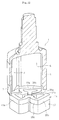
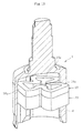
Fig. 15 uses so-called double-roller type roller members each including the inner roller and the outer roller. However, as illustrated inFig. 16 and Fig. 17 , the tripod type constant velocity universal joint may use so-called single-roller type roller members each including a roller fitted onto a cylindrical outer peripheral surface of the leg shaft through a plurality of needle rollers in such a manner that the roller is rotatable. In this case, each of theleg shafts 9 includes a cylindrical outerperipheral surface 74, and anannular ring groove 76 formed in vicinity of an end of each of the leg shafts. Aroller 80 is fitted onto an outer periphery of each of theleg shaft 9 through a plurality ofneedle rollers 82 in such a manner that theroller 80 is rotatable. The cylindrical outerperipheral surface 74 of each of theleg shafts 9 provides an inner raceway surface for the plurality ofneedle rollers 82. Theroller 80 includes a cylindrical inner peripheral surface to provide an outer raceway surface for the plurality ofneedle rollers 82. - The plurality of
needle rollers 82 are held in contact with anouter washer 84 on outer end surfaces of the plurality of needle rollers, and with aninner washer 88 on end surfaces opposite to the outer end surfaces of the plurality of needle rollers, when viewed from a radial direction of theleg shaft 9. Theouter washer 84 is regulated from moving in the axial direction by acirclip 86 mounted into thering groove 76. As a result, the plurality ofneedle rollers 82 are also regulated from moving in the axial direction. - Generally, the
roller guide surfaces 7a of theouter joint member 1 are subjected to heat hardening treatment. As the heat hardening treatment, there is induction quenching. The induction quenching is mainly divided into a one-shot quenching method of performing heat treatment at a fixed position (Patent Literature 1), and a mobile quenching method in which the coil is moved relative to the outer joint member (Patent Literature 2). - In the one-shot quenching, there is used, as illustrated in
Fig. 10 andFig. 11 , a high-frequency heating apparatus including a high-frequencyinduction heating coil 17. In this case, the high-frequencyinduction heating coil 17 includesheating portions track grooves 6 of theouter joint member 1. Therefore, it is possible to both heat and rapidly cool theroller guide surfaces 7a over an axial entire region of the joint at one time. Further, inPatent Literature 1 described above, in order to prevent hardened layers from being formed in inner surfaces of the larger radially-inner portions 7c, non-conductive ferrite cores are fitted in an induction coil. Therefore, by using the above-mentioned high-frequency induction heating apparatus, there are formed hardened layers S only in surface layers of theroller guide surfaces 7a as illustrated inFig. 11 . - Further, in the mobile quenching method, another high-frequency induction heating apparatus illustrated in
Fig. 12 to Fig. 14 is used. The high-frequency induction heating apparatus includes: acoil 18 wound to have a three-leaf clover shape; and acooling jacket 19 attached to thecoil 18. Thecoil 18 includesheating portions heating portions 18a includes:curved portions roller guide surfaces 7a; and astraight portion 20b opposed to the larger radially-inner portion 7c. Note that, thecooling jacket 19 has a three-leaf clover shape similarly to thecoil 18. - In the mobile quenching method, the
coil 18 and thecooling jacket 19 are moved along an axial direction in themouth portion 4 of theouter joint member 1. Along with the above-mentioned movement, heated surfaces (roller guide surfaces 7a and larger radially-inner portions 7c) are heated. Following the above-mentioned heating, the heated surfaces are rapidly cooled with cooling water injected through thecooling jacket 19. Thus, theroller guide surfaces 7a and the larger radially-inner portions 7c are subjected to the heat hardening treatment. In this manner, the hardened layers S are formed. -
- [PTL 1] Japanese Examined Patent Publication No.
Sho 61-34481 - [PTL 2] Japanese Examined Utility Model Publication No.
Hei 03-26335 - In the general one-shot quenching, temporal heating and temporal cooling are conducted, and hence there is a demerit in that distortion is easy to occur in a thin-walled portion and the like. In contrast, the mobile quenching has effects of stabilizing occurring distortion, uniforming a thickness of the quenched and hardened layer, and the like.
- By the way, taking a function of the joint in consideration, there is no problem as long as the hardened layers are provided at least in the
roller guide surfaces 7a. However, if the mobile quenching is performed, theroller guide surfaces 7a and the larger radially-inner portions 7c are subjected to the heat hardening treatment, and hence the hardened layers S are formed as illustrated inFig. 14 . - In an outer periphery of the
outer joint member 1, a boot band fasteninggroove 5 is formed, and a portion in which the boot band fasteninggroove 5 is provided is thin. Therefore, the hardened layers S in the thin-walled portion may give way to a side of the outer periphery. Thus, the above-mentioned portion may be weaken in terms of a strength thereof. Therefore, there is a demerit in that a degree of freedom for designing is limited, for example a downsizing of the joint becomes difficult. - Therefore, the present invention has been made in view of the above-mentioned circumstances, and it is an object of the present invention to provide a heat treatment method capable of molding, by mobile quenching of induction quenching, an outer joint member of a tripod type constant velocity universal joint excellent in a strength thereof without forming hardened layers in larger radially-inner portions, and to provide the outer joint member and the tripod type constant velocity universal joint which are manufactured by the above-mentioned heat treatment method.
- According to a first aspect of the present invention, there is provided a heat treatment method for forming hardened layers in roller guide surfaces of an outer joint member, including: performing mobile quenching in such a manner that a high-frequency induction heating coil is moved in an axial direction relative to the outer joint member including track grooves which are formed at three positions of an inner periphery of the outer joint member, and each of which includes: the roller guide surfaces facing to each other in a circumferential direction of the outer joint member; and a larger radially-inner portion provided between both of the roller guide surfaces; providing heating-suppressing portions for the larger radially-inner portions in positions of the high-frequency induction heating coil, the positions being respectively opposed to the larger radially-inner portions; and setting a range corresponding to a boot mounting portion in at least a center portion in the circumferential direction in each of the larger radially-inner portions of the outer joint member to be an unquenched portion by cutting out the magnetic field lines with the magnetic field line cut-out bodies.
- According to the first aspect of the present invention, in the heat treatment method, it is possible to form the hardened layers in the roller guide surfaces by the mobile quenching of induction quenching without forming the hardened layer in the range corresponding to the boot mounting portion in at least the center portion in the circumferential direction in each of the larger radially-inner portions of the outer joint member.
- The heating-suppressing portions for the larger radially-inner portions include magnetic field line cut-out bodies for cutting out magnetic field lines generated through the high-frequency induction heating coil. The magnetic field line cut-out bodies include, for example, ferromagnetic cores fitted into portions of the high-frequency induction heating coil, at which the ferromagnetic cores come close to the larger radially-inner portions, respectively. Further, each of the ferromagnetic cores includes, for example, a silicon steel.
- According to a second aspect of the present invention, there is provided a heat treatment method for forming hardened layers in roller guide surfaces of an outer joint member, including: performing mobile quenching in such a manner that a high-frequency induction heating coil is moved in an axial direction relative to the outer joint member including track grooves which are formed at three positions of an inner periphery of the outer joint member, and each of which includes: the roller guide surfaces facing to each other in a circumferential direction of the outer joint member; and a larger radially-inner portion provided between both of the roller guide surfaces; and setting a range corresponding to a boot mounting portion in at least a center portion in the circumferential direction in each of the larger radially-inner portions of the outer joint member to be an unquenched portion by the high-frequency induction heating coil including retracted portions to be prevented from coming close to the larger radially-inner portions.
- According to the second aspect of the present invention, in the heat treatment method, the high-frequency induction heating coil includes the retracted positions to be prevented from coming close to the larger radially-inner portions. Therefore, the range corresponding to the boot mounting portion in at least the center portion in the circumferential direction in each of the larger radially-inner portions is prevented from being heated by the heat treatment, and the range becomes the unquenched portion.
- According to a third aspect of the present invention, there is provided a heat treatment method for forming hardened layers in roller guide surfaces of an outer joint member, including: performing mobile quenching in such a manner that a high-frequency induction heating coil is moved in an axial direction relative to the outer joint member including track grooves which are formed at three positions of an inner periphery of the outer joint member, and each of which includes: the roller guide surfaces facing to each other in a circumferential direction of the outer joint member; and a larger radially-inner portion provided between both of the roller guide surfaces; providing, on an outer diameter side of the roller guide surfaces of the outer joint member, flange portions opposed to a roller member; and setting at least a range corresponding to a boot mounting portion in each of the larger radially-inner portions to be an unquenched portion serving as an unheated portion.
- According to the third aspect of the present invention, in the heat treatment method, on an outer diameter side of the roller guide surfaces of the outer joint member, the flange portions opposed to the roller member are provided. Therefore, at least the range corresponding to the boot mounting portion in each of the larger radially-inner portions is prevented from being heated by the heat treatment, and the range becomes the unquenched portion.
- Each of the heat treatment methods may include: forming a smaller radially-inner portion between the larger radially-inner portions of the outer joint member; and forming a hardened layer in the smaller radially-inner portion by the mobile quenching. Further, each of the heat treatment methods may further include setting an entire of each of the larger radially-inner portions of the outer joint member to be an unquenched portion.
- On a joint deep side of the larger radially-inner portions of the outer joint member, a boot mounting groove or the like is prevented from being formed in the radially-outer surface of the outer joint member. Therefore, it is possible to prevent unquenched portions from being formed on a joint deep side of the larger radially-inner portions of the outer joint member. Further, hardened layers may be formed only in the roller guide surfaces on an inner diameter side of the outer joint member.
- According to the present invention, a tripod type constant velocity universal joint includes: the outer joint member treated by the heat treatment method; a tripod member including three leg shafts arranged in the outer joint member and protruded in a radial direction; and a roller member mounted to each of the three leg shafts of the tripod member and guided in an axial direction of the outer joint member along the roller guide surfaces.
- The roller member is fitted into a spherical outer peripheral surface of each of the three leg shafts to be capable of oscillating, and is guided in the axial direction of the outer joint member along the roller guide surfaces.
- The roller member may include: a roller inserted in each of track grooves of the outer joint member; and a ring fitted onto each of the three leg shafts, for supporting the roller to be rotatable. The roller may be movable in the axial direction of the outer joint member along the roller guide surfaces, and an inner peripheral surface of the ring may be formed to have a circular-arc convex cross-section. In addition, an outer peripheral surface of each of the three leg shafts may be formed to have a straight shape in a longitudinal section of each of the three leg shafts and to be held, in a cross-section of each of the three leg shafts, in contact with the inner peripheral surface of the ring in a direction orthogonal to an axis of the tripod type constant velocity universal joint and form a gap with respect to the inner peripheral surface of the ring in an axial direction of the tripod type constant velocity universal joint.
- It is preferred that the cross-section of each of the three leg shafts be set to have a substantially oval shape including a longitudinal axis orthogonal to the axis of the tripod type constant velocity universal joint.
- In the heat treatment method of the present invention, the hardened layers can be formed in the roller guide surfaces without forming the hardened layer in the range corresponding to the boot mounting portion of at least the center portion in the circumferential direction in each of the larger radially-inner portions of the outer joint member. Therefore, it is possible to ensure a strength of the opening portion of the outer joint member. In addition, the mobile quenching is employed as a quenching method, and hence distortion is difficult to occur, and a thickness of the quenched and hardened layers can be uniformed.
- As long as the magnetic field line cut-out bodies include the ferromagnetic cores, it is possible to stably form the unquenched portions. Further, each of the ferromagnetic core may include, for example, a silicon steel. In this case, without using a specific (special) material, it is possible to attach the ferromagnetic cores to the high-frequency induction heating coil at relatively low cost.
- The unquenched portions may be formed in the entire larger radially-inner portions of the outer joint member, or the unquenched portions may be prevented from being formed on the joint deep side of the larger radially-inner portions. Otherwise, the hardened layers may be formed only in the roller guide surfaces. Even in this case, without deteriorating a function as the outer joint member, it is possible to form the hardened layers in an optimum range.
- The outer joint member of the tripod type constant velocity universal joint of the present invention is treated by the heat treatment method. Therefore, the outer joint member is stable in terms of a strength thereof and is excellent in durability.
- The tripod type constant velocity universal joint of the present invention uses the outer joint member treated by the heat treatment method, and hence becomes a high-quality tripod type constant velocity universal joint excellent in the durability. In addition, a degree of freedom for designing, for example, downsizing of the joint increases. Further, the outer joint member is applicable to various types of tripod type constant velocity universal joints.
-
- [
Fig. 1 ] A sectional view illustrating an embodiment of the present invention and illustrating a relation between a high-frequency induction heating coil and an outer joint member which are used for a heat treatment method. - [
Fig. 2 ] A perspective view of the high-frequency induction heating coil. - [
Fig. 3 ] A plan view of the high-frequency induction heating coil. - [
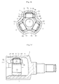
Fig. 4 ] A cross-sectional view of a tripod type constant velocity universal joint of the present invention. - [
Fig. 5 ] A longitudinal sectional view of the tripod type constant velocity universal joint. - [
Fig. 6 ] A main-part sectional view of the tripod type constant velocity universal joint. - [
Fig. 7 ] Amain-part sectional view of an outer joint member according to anther embodiment. - [
Fig. 8 ] A plan view of another high-frequency induction heating coil. - [
Fig. 9 ] A main-part sectional view of another tripod type constant velocity universal joint of the present invention. - [
Fig. 10 ] A perspective view of a conventional tripod type constant velocity universal joint in a heat treatment state by one-shot quenching. - [
Fig. 11 ] A main-part sectional view of the conventional tripod type constant velocity universal joint in the heat treatment state by the one-shot quenching. - [
Fig. 12 ] A perspective view of a high-frequency induction heating coil and an outer joint member in a heat treatment state by a mobile quenching, which illustrates a conventional example. - [
Fig. 13 ] A perspective view of the high-frequency induction heating coil and the outer joint member in a heat treatment state by the mobile quenching, which illustrates a conventional example. - [
Fig. 14 ] A main-part sectional view of the conventional tripod type constant velocity universal joint in the heat treatment state by the mobile quenching. - [
Fig. 15 ] A cross-sectional view of the tripod type constant velocity universal joint using the outer joint member molded by a conventional heat treatment method. - [
Fig. 16 ] A cross-sectional view of a tripod type constant velocity universal joint of a single roller type. - [
Fig. 17 ] A longitudinal sectional view of the tripod type constant velocity universal joint illustrated inFig. 16 . - Hereinafter, embodiments of the present invention are described with reference to the drawings.
-
Fig. 1 illustrates a main part sectional view of an outer joint member subjected to heat hardening treatment by a heat treatment method according to the present invention. The outer joint member is used in a tripod type constant velocity universal joint as illustrated inFig. 4 to Fig. 6 . The tripod type constant velocity universal joint includes: an outerjoint member 21; atripod member 22 serving as an inner joint member; andtorque transmission members 23. - The outer
joint member 21 includes: a cup-like mouth portion 24 opened at one end thereof; and trackgrooves 26 each extending in an axial direction from positions trisecting an inner periphery thereof in the circumferential direction. Themouth portion 24 has a non-cylindrical shape in which larger-diameter portions 24a and smaller-diameter portions 24b are alternately arranged when viewed in a cross-section. That is, themouth portion 24 forms the larger-diameter portions 24a and the smaller-diameter portions 24b. Thus, in an inner peripheral surface of the mouth portion, there are formed the threetrack grooves 26 each extending in the axial direction. - In side walls facing to each other in the circumferential direction of each of
track grooves 26, there are formed roller guide surfaces (roller sliding surfaces) 27, 27. Further, a radially-inner surface exhibits a shape of a three-petal corolla of a flower, in which smaller radially-inner portions 45 and larger radially-inner portions 46 are alternately connected together through intermediation of the roller guide surfaces 27 in the circumferential direction. That is, in the outerjoint member 21, the roller guide surfaces 27 andtrack grooves 6 are formed at three positions in an inner periphery of the outer joint member. In this case, the roller guide surfaces 27 face to each other in the circumferential direction, and thetrack grooves 6 include the larger radially-inner portions 46 each provided between both of the roller guide surfaces 27, 27. - The
tripod member 22 includes aboss 28 andleg shafts 29. Theboss 28 is provided with a spline hole or aserration hole 31 which is coupled to a shaft (not shown) to be allowed to transmit torque. Theleg shafts 29 each protrude in a radial direction from positions trisecting theboss 28 in the circumferential direction. - Further, each of the torque transmission members (roller members) 23 includes: a
roller 32 including a ring-like body including a radially-outer surface 33 formed into a convex spherical surface; and aring 35 fitted into theroller 32 through intermediation of a plurality ofrollers 36. That is, theroller 32 and thering 35 are unitized through intermediation of the plurality ofrollers 36. Those members and the like constitute a roller assembly (roller member). In this case, theroller 32 can be called an outer roller, and thering 35 can be called an inner roller. - That is, the ring (inner roller) 35 is fitted onto an outer peripheral surface of the
leg shaft 29. A cylindrical outer peripheral surface of theinner roller 35 is used as an inner raceway surface, and a cylindrical inner peripheral surface of theouter roller 32 is used as an outer raceway surface. Between the inner raceway surface and the outer raceway surface, there are theneedle rollers 36 are interposed to be rotatable. Theneedle rollers 36 are incorporated under a so-called full state, in which a large number of the rollers are provided as much as possible and a retainer is not used. Note that, in circular grooves formed in end-portion inner-peripheral surfaces of theouter roller 32, there are attachedwashers 37 for detachment of theneedle rollers 36. - A radially-inner surface of the
ring 35 is formed into a circular-arc convex surface. Further, a radially-outer surface of theleg shaft 29 is set to have a straight shape in a longitudinal section. The radially-outer surface of theleg shaft 29 is set, in a cross-section, as illustrated inFig. 5 and Fig. 6 , to be held in contact with the radially-inner surface of thering 35 in a direction orthogonal to an axis of the joint and to formgaps 40 with respect to the radially-inner surface of thering 35 in the axial direction of the joint. That is, the cross-section of theleg shaft 29 is set to have a substantially oval shape including a longitudinal axis orthogonal to the axis of the joint. - By the way, an opening portion of the outer
joint member 21 is sealed with a boot (not shown). The boot includes a larger-diameter portion, a smaller-diameter portion, and a bellows portion coupling the larger-diameter portion and the smaller-diameter portion. Further, in a side of the opening portion of the radially-outer portion of the outerjoint member 21, there is formed aboot mounting portion 44 including arecess groove 43 as illustrated inFig. 5 . Theboot mounting portion 44 is fitted onto the larger-diameter portion of the boot, and the larger-diameter portion is fastened with the boot band. In this manner, the larger-diameter portion of the boot is mounted onto theboot mounting portion 44 of the outerjoint member 21. Further, as described above, the shaft is coupled to thetripod member 22. A boot mounting portion including a recess groove is formed also in the shaft. The boot mounting portion of the shaft is fitted onto the smaller-diameter portion of the boot, and the smaller-diameter portion is fastened with the boot band. In this manner, the smaller-diameter portion of the boot is mounted onto the boot mounting portion of the shaft. - By the way, in a radially-inner surf ace of the
mouth portion 24 of the outerjoint member 21, there are formed hardened layers S (seeFig. 1 ). In this case, in each of the larger radially-inner portions 46, there is formed anunquenched portion 50. Note that, in the illustrated example, theunquenched portion 50 is not formed in the entire larger radially-inner portion 46, and the hardened layers S are formed in circumferential ends of the larger radially-inner portion 46. - For formation of the hardened layers S, there is used a high-
frequency heating apparatus 52 including a high-frequencyinduction heating coil 51 illustrated inFig. 2 andFig. 3 . The high-frequencyinduction heating coil 51 includes threeheating portions heating portions curved portions straight portions 54 to face to the larger radially-inner portions 46. - Further, heating-suppressing portions for the larger radially-
inner portions 46 are provided in positions of the high-frequencyinduction heating coil 56, the positions being respectively opposed to the larger radially-inner portions 46. Specifically, the heating-suppressing portions include magnetic field line cut-out bodies A. In this case, a recessedportion 55 is provided in a center portion of a surface of each of thestraight portions 54, the surface being opposed to each of the larger radially-inner portions. In the recessedportion 55, the magnetic field line cut-out body A including theferromagnetic core 56 is arranged. A longitudinal length L of theferromagnetic core 56 is set to be smaller than a longitudinal length L1 of the recessedportion 55. A lateral length W of theferromagnetic core 56 is set to be substantially the same as a lateral length W1 of the recessedportion 55. Therefore, upper surfaces of theheating portions ferromagnetic core 56 are arranged to be flush with each other. Lower surfaces of theheating portions ferromagnetic core 56 are arranged to be flush with each other. Further, between side surfaces of the recessedportion 55 and corresponding side surfaces of theferromagnetic core 56, there are respectively formedgaps 60. Note that, a thickness dimension T of theferromagnetic core 56 is set to be larger than a depth dimension T1 of the recessedportion 55. Anouter surface 56a of theferromagnetic core 56 protrudes slightly to a side of the larger radially-inner portion with respect to an outer surface (surface opposed to the larger radially-inner portion) 54a of thestraight line 54 of theheating portion 51A (51B, 51C). - Note that, though not illustrated, a cooling jacket as illustrated in
Fig. 12 or the like is attached to a lower portion of the high-frequencyinduction heating coil 51. The cooling jacket includes a cooling piping in which cooling water flows, and has a shape substantially corresponding to a shape of the high-frequencyinduction heating coil 51. - The high-frequency
induction heating coil 51 is supplied with high-frequency current from a high-frequency power source (not shown). In this case, the high-frequency current flows through theheating portion 51A, theheating portion 51B, and theheating portion 51C in this order. As described above, when the high-frequency current flows, an induced electromotive force is generated due to an electromagnetic induction effect. Due to the electromagnetic induction effect, Joule heat is generated. As a result, the roller guide surfaces 27 and the like of the outerjoint member 21 can be heated. - Under the above-mentioned state, the high-frequency
induction heating coil 51 is continuously moved from a side of an opening portion of the mouth portion to a deep side of the mouth portion. In this manner, the roller guide surfaces 27 and the like are heated from the side of the opening portion to the deep side. Further, along with the above-mentioned movement of the high-frequencyinduction heating coil 51, the cooling jacket is moved. Thus, a cooling fluid (cooling water) is injected from the cooling jacket to a heated portion of the outerjoint member 21, to thereby cool the heated portion. That is, correspondingly to a relative movement of the high-frequencyinduction heating coil 51, the roller guide surfaces 27 and the like are subsequently heated. Then, following the above-mentioned heating operation, the heated portion is rapidly cooled with the cooling fluid. In this way, induction quenching is performed. - By the way, in each of the
heating portions induction heating coil 51, theferromagnetic core 56 is provided. Therefore, theferromagnetic core 56 cuts out magnetic field lines generated through the high-frequencyinduction heating coil 51. That is, the ferromagnetic core is made of amaterial having high magnetic permeability and is provided to the coil, and hence the ferromagnetic core has an effect of amplifying power through concentrating the magnetic field lines to a work. At the same time, the ferromagnetic core is used for cutting out the magnetic field lines and for preventing undesired heating. Therefore, as in the present invention, if the ferromagnetic core is used for heat hardening treatment for the radially-inner surface of the outerjoint member 21 of the tripod type constant velocity universal joint, theunquenched portions 50 can be formed in the larger radially-inner portions 46. That cannot be performed by conventional mobile quenching. Therefore, as illustrated inFig. 1 , in each of the larger radially-inner portions 46 to which theferromagnetic core 56 faces, theunquenched portion 50 in which the hardened layers S are prevented from being formed is formed. - In the heat treatment method of the present invention, without forming the hardened layers S in the larger radially-
inner portions 46 of the outerjoint member 21, the hardened layers S can be formed in the roller guide surfaces 27, 27. Therefore, it is possible to ensure a strength of the opening portion of the outerjoint member 21. In addition, the mobile quenching is employed as a quenching method, and hence distortion is difficult to occur, and a thickness of the quenched and hardened layers can be uniformed. - As long as the magnetic field line cut-out bodies A include the
ferromagnetic cores 56, it is possible to stably form theunquenched portions 50. Further, theferromagnetic cores 56 may includes, for example, a silicon steel. In this case, without using a specific (special) material, it is possible to attach theferromagnetic cores 56 to the high-frequencyinduction heating coil 51 at relatively low cost. - As described above, the outer
joint member 21 in which the hardened layers S are formed is treated by the heat treatment method. Therefore, the outerjoint member 21 is stable in terms of a strength thereof and is excellent in durability. Further, the outerjoint member 21 molded in the above-mentioned manner can be used for assembling the tripod type constant velocity universal joint as illustrated inFig. 4 to Fig. 6 or the like. Therefore, the tripod type constant velocity universal joint uses the outer j oint member treated by the heat treatment method, and hence becomes a high-quality tripod type constant velocity universal joint excellent in the durability. In addition, a degree of freedom for designing, for example, downsizing of the joint increases. - Further, in the tripod type constant velocity universal joint as illustrated in
Fig. 4 to Fig. 6 or the like, each of the torque transmission members (roller members) 23 is allowed to be tilted in thetrack groove 26. Thus, tilting of the roller is capable of absorbing tilting of the leg shaft when torque is transmitted under a state in which the joint forms an operating angle. Therefore, that contributes to a reduction of a sliding resistance, and therefore, a reduction of an induced thrust. Therefore, the constant velocity universal joint of the present invention can contributes, when applied in particular to a drive shaft in an automobile, optimization of noise, vibration, and harshness (NVH) performance of the automobile associated with the magnitude of the sliding resistance and the induced thrust. Further, a degree of freedom for a design of an under body of the automobile. - By the way, in the embodiment, the
unquenched portion 50 is formed along the axial direction in the center portion in the circumferential direction of the larger radially-inner portion 46. However, theunquenched portion 50 may be formed in the entire larger radially-inner portion 46, or theunquenched portion 50 may not be formed on a joint deep side of the larger radially-inner portion 46. That is, the hardened layer S may be formed on the joint deep side of the larger radially-inner portion 46 except for the opening portion (entrance portion) side corresponding to theboot mounting portion 44 and for a portion thereof situated at a regularly used position. That is because, even if the hardened layer is formed on the joint deep side of the larger radially-inner portion 46, an effect against the strength of the outer joint member is small. Further, regarding the smaller radially-inner portion 45, the hardened layer S may be formed or may not be formed. The hardened layer S may be formed only in theroller guide surface 27. Therefore, without deteriorating a function as the outerjoint member 21, it is possible to form the hardened layer S in an optimum range. - Next,
Fig. 7 illustrates an outerjoint member 21 of another embodiment. In this case, on an outer diameter side of theroller guide surface 27 of the outerjoint member 21, there are providedflange portions 61 opposed to theroller member 23. An inner surface of the larger radially-inner portion 46 is set to be theunquenched portion 50. Further, the hardened layers S are formed also with respect to the inner surfaces of theflange portions 61. Theroller member 23 is brought into contact with theflange portions 61, and hence the hardened layers S are formed in theflange portions 61. Even in this case, the hardened layer S may be formed on the joint deep side of the larger radially-inner portion 46 except for the opening portion (entrance portion) side corresponding to theboot mounting portion 44 and for a portion thereof situated at a regularly used position. - Even in a case of the outer
joint member 21 illustrated inFig. 7 , the high-frequency heating apparatus illustrated inFig. 1 to Fig. 3 or the like can be used to form the hardened layers S. Therefore, the outerjoint member 21 in which the above-mentioned hardened layers S are formed is treated by the heat treatment method, and hence the outer joint member is stable in terms of the strength thereof and is excellent in the durability. Further, the tripod type constant velocity universal joint using the outerjoint member 21 molded in the above-mentioned manner becomes a high-quality tripod type constant velocity universal joint excellent in the durability. - By the way, in each of the
heating portions induction heating coil 51 of the high-frequency heating apparatus, the recessedportions 55 respectively facing to the larger radially-inner portions 46 are formed. That is, the high-frequencyinduction heating coil 51 includes retracted positions to be prevented from coming close to the larger radially-inner portions 46. Therefore, without providing the magnetic field line cut-out bodies A including theferromagnetic cores 56 or the like, it is possible to prevent the larger radially-inner portions 46 from being heated. Consequently, as the high-frequencyinduction heating coil 51, the high-frequency induction heating coil without theferromagnetic cores 56 as illustrated inFig. 8 may be used. Even in this case, it is possible to set the larger radially-inner portions 46 to be theunquenched portions 50. - Next,
Fig. 9 illustrates another tripod type constant velocity universal joint. In this case, each of the roller members is fitted onto a spherical outerperipheral surface 29a of theleg shaft 29 to be capable of oscillating. The roller member is guided along the roller guide surfaces 27, 27 in the axial direction of the outerjoint member 21. That is, the roller member includes: arotation support 71 into which the spherical outerperipheral surface 29a of theleg shaft 29 is fitted; and anouter roller 73 on a side of an outer periphery of therotation support 71 to be rotatable through theneedle rollers 72. - It is possible to set the larger radially-
inner portions 46 of the outerjoint member 21 to be theunquenched portions 50 even in the following cases: a case of the outerjoint member 21 of the above-mentioned tripod type constant velocity universal joint; a case of the high-frequency heating apparatus including the high-frequencyinduction heating coil 51 arranged in the magnetic field line cut-out bodies A (ferromagnetic cores 56) illustrated inFig. 2 to Fig. 4 or the like; and a case of the high-frequency heating apparatus including the high-frequencyinduction heating coil 51 without the magnetic field line cut-out bodies A (ferromagnetic cores 56) as illustrated inFig. 8 . - Therefore, the tripod type constant velocity universal joint illustrated in
Fig. 9 becomes a high-quality tripod type constant velocity universal joint excellent in the durability. In addition, a degree of freedom for designing, for example, downsizing of the joint increases. - Although the embodiments of the present invention is described above, the present invention is not limited to the above-mentioned embodiments, and various modifications can be made. For example, the material of the
ferromagnetic cores 56 may include, in addition to the silicon steel, a soft steel, and a ceramic such as a ferrite. Further, the tripod type constant velocity universal joint ofFig. 4 or the like uses a so-called double-roller type roller members each including the inner roller and the outer roller. However, as illustrated inFig. 16 and Fig. 17 , the tripod type constant velocity universal joint may use so-called single-roller type roller members each including theroller 80 fitted onto the cylindrical outer peripheral surface of theleg shaft 9 through the plurality ofneedle rollers 82 in such a manner that theroller 80 is rotatable. -
- 21
- outer joint member
- 22
- tripod member
- 23
- torque transmission member (roller member)
- 26
- track groove
- 27
- roller guide surface
- 28
- boss
- 29
- leg shaft
- 29a
- spherical outer peripheral surface
- 32
- outer roller
- 35
- ring
- 35
- inner roller
- 40
- gap
- 45
- smaller radially-inner portion
- 46
- larger radially-inner portion
- 50
- unquenched portion
- 51
- high-frequency induction heating coil
- 56
- ferromagnetic core
- 61
- flange
- A
- magnetic field line cut-out body
- S
- hardened layer
Claims (15)
- A heat treatment method for forming hardened layers in roller guide surfaces of an outer joint member, comprising:performing mobile quenching in such a manner that a high-frequency induction heating coil is moved in an axial direction relative to the outer joint member comprising track grooves which are formed at three positions of an inner periphery of the outer joint member, and each of which comprises:the roller guide surfaces facing to each other in a circumferential direction of the outer joint member; anda larger radially-inner portion provided between both of the roller guide surfaces;providing heating-suppressing portions for the larger radially-inner portions in positions of the high-frequency induction heating coil, the positions being respectively opposed to the larger radially-inner portions; andsetting a range corresponding to a boot mounting portion in at least a center portion in the circumferential direction in each of the larger radially-inner portions of the outer joint member to be an unquenched portion by cutting out the magnetic field lines with the magnetic field line cut-out bodies.
- A heat treatment method according to claim 1, wherein:the heating-suppressing portions for the larger radially-inner portions comprise magnetic field line cut-out bodies for cutting out magnetic field lines generated through the high-frequency induction heating coil; andthe magnetic field line cut-out bodies comprise ferromagnetic cores fitted into portions of the high-frequency induction heating coil, at which the ferromagnetic cores come close to the larger radially-inner portions, respectively.
- A heat treatment method according to claim 2, wherein each of the ferromagnetic cores comprises a silicon steel.
- A heat treatment method for forming hardened layers in roller guide surfaces of an outer joint member, comprising:performing mobile quenching in such a manner that a high-frequency induction heating coil is moved in an axial direction relative to the outer joint member comprising track grooves which are formed at three positions of an inner periphery of the outer joint member, and each of which comprises:the roller guide surfaces facing to each other in a circumferential direction of the outer joint member; anda larger radially-inner portion provided between both of the roller guide surfaces; andsetting a range corresponding to a boot mounting portion in at least a center portion in the circumferential direction in each of the larger radially-inner portions of the outer joint member to be an unquenched portion by the high-frequency induction heating coil comprising retracted portions to be prevented from coming close to the larger radially-inner portions.
- A heat treatment method for forming hardened layers in roller guide surfaces of an outer joint member, comprising:performing mobile quenching in such a manner that a high-frequency induction heating coil is moved in an axial direction relative to the outer joint member comprising track grooves which are formed at three positions of an inner periphery of the outer joint member, and each of which comprises:the roller guide surfaces facing to each other in a circumferential direction of the outer joint member; anda larger radially-inner portion provided between both of the roller guide surfaces;providing, on an outer diameter side of the roller guide surfaces of the outer joint member, flange portions opposed to a roller member; andsetting at least a range corresponding to a boot mounting portion in each of the larger radially-inner portions to be an unquenched portion serving as an unheated portion.
- A heat treatment method according to claim 5, further comprising forming hardened layers in surfaces of the flange portions, the surfaces being opposed to the roller member.
- A heat treatment method according to any one of claims 1 to 6, further comprising:forming a smaller radially-inner portion between the larger radially-inner portions of the outer joint member; andforming a hardened layer in the smaller radially-inner portion by the mobile quenching.
- A heat treatment method according to claim 1, further comprising setting an entire of each of the larger radially-inner portions of the outer joint member to be an unquenched portion.
- A heat treatment method according to claim 1, further comprising preventing unquenched portions from being formed on a joint deep side of the larger radially-inner portions of the outer joint member.
- A heat treatment method according to claim 1, further comprising forming hardened layers only in the roller guide surfaces on an inner diameter side of the outer joint member.
- An outer joint member of a tripod type constant velocity universal joint, which is treated by the heat treatment method according to any one of claims 1 to 10.
- A tripod type constant velocity universal joint, comprising:the outer joint member according to claim 11;a tripod member comprising three leg shafts arranged in the outer joint member and protruded in a radial direction; anda roller member mounted to each of the three leg shafts of the tripod member and guided in an axial direction of the outer joint member along the roller guide surfaces.
- A tripod type constant velocity universal joint according to claim 12, wherein the roller member is fitted into a spherical outer peripheral surface of each of the three leg shafts to be capable of oscillating, and is guided in the axial direction of the outer joint member along the roller guide surfaces.
- A tripod type constant velocity universal joint according to claim 12, wherein:the roller member comprises:a roller inserted in each of track grooves of the outer joint member; anda ring fitted onto each of the three leg shafts, for supporting the roller to be rotatable;the roller is movable in the axial direction of the outer joint member along the roller guide surfaces;an inner peripheral surface of the ring is formed to have a circular-arc convex cross-section; andan outer peripheral surface of each of the three leg shafts is formed to have a straight shape in a longitudinal section of each of the three leg shafts and to be held, in a cross-section of each of the three leg shafts, in contact with the inner peripheral surface of the ring in a direction orthogonal to an axis of the tripod type constant velocity universal joint and form a gap with respect to the inner peripheral surface of the ring in an axial direction of the tripod type constant velocity universal joint.
- A tripod type constant velocity universal joint according to claim 14, wherein the cross-section of each of the three leg shafts is set to have a substantially oval shape including a longitudinal axis orthogonal to the axis of the tripod type constant velocity universal joint.
Applications Claiming Priority (2)
| Application Number | Priority Date | Filing Date | Title |
|---|---|---|---|
| US13/037,458 US8454767B2 (en) | 2011-03-01 | 2011-03-01 | Heat treatment method, outer joint member, and tripod type constant velocity universal joint |
| PCT/JP2012/054324 WO2012117920A1 (en) | 2011-03-01 | 2012-02-22 | Thermal processing method, outer connecting member, and tripod-type constant velocity universal joint |
Publications (3)
| Publication Number | Publication Date |
|---|---|
| EP2682622A1 true EP2682622A1 (en) | 2014-01-08 |
| EP2682622A4 EP2682622A4 (en) | 2014-12-17 |
| EP2682622B1 EP2682622B1 (en) | 2019-07-31 |
Family
ID=46752547
Family Applications (1)
| Application Number | Title | Priority Date | Filing Date |
|---|---|---|---|
| EP12752929.5A Active EP2682622B1 (en) | 2011-03-01 | 2012-02-22 | Thermal processing method, outer connecting member, and tripod-type constant velocity universal joint |
Country Status (5)
| Country | Link |
|---|---|
| US (1) | US8454767B2 (en) |
| EP (1) | EP2682622B1 (en) |
| JP (1) | JP6012981B2 (en) |
| CN (1) | CN103415718B (en) |
| WO (1) | WO2012117920A1 (en) |
Families Citing this family (10)
| Publication number | Priority date | Publication date | Assignee | Title |
|---|---|---|---|---|
| RU2672968C2 (en) * | 2013-06-22 | 2018-11-21 | Индактохит, Инк. | Single-shot inductor for induction heating of complex workpieces |
| JP6291701B2 (en) * | 2014-04-01 | 2018-03-14 | 高周波熱錬株式会社 | Induction hardening work, work having a hardened layer, and induction hardening method for hardening work |
| KR101456216B1 (en) | 2014-08-08 | 2014-10-31 | 김회욱 | Bed-Coil Device For A Heat Treatment With High Frequency. |
| JP2017180675A (en) * | 2016-03-30 | 2017-10-05 | Ntn株式会社 | Tripod type constant velocity universal joint and heat treatment method for tripod member |
| JP6379151B2 (en) * | 2016-10-20 | 2018-08-22 | Thk株式会社 | Exercise guidance device |
| IT201700056454A1 (en) * | 2017-05-24 | 2018-11-24 | Saet Spa | DEVICE AND METHOD FOR TEMPERING INDUCTION SINGLE SHOT OF MECHANICAL COMPONENTS |
| DE102018118634A1 (en) * | 2018-08-01 | 2020-02-06 | Schaeffler Technologies AG & Co. KG | Procedure for mounting a tripod roller, tripod roller and constant velocity joint with the tripod roller |
| JP7309677B2 (en) * | 2019-12-05 | 2023-07-18 | 高周波熱錬株式会社 | Heating coil and hardening device |
| US12331797B2 (en) | 2020-05-26 | 2025-06-17 | Aircraft Gear Corporation | Method of carburizing driveline components |
| KR102529463B1 (en) * | 2020-10-06 | 2023-05-09 | 현대자동차주식회사 | A manufacturing method of a trunnion for tripod constant velocity joint and the trunnion manufactured by the method and a heat treatment device of the trunnion |
Family Cites Families (22)
| Publication number | Priority date | Publication date | Assignee | Title |
|---|---|---|---|---|
| JPS5827330B2 (en) * | 1979-11-07 | 1983-06-08 | 電気興業株式会社 | Induction hardening method for the periphery of a cylindrical body |
| JPS615752Y2 (en) * | 1980-03-10 | 1986-02-21 | ||
| JPS6322634Y2 (en) * | 1981-03-27 | 1988-06-21 | ||
| US4401485A (en) * | 1981-07-22 | 1983-08-30 | Park-Ohio Industries, Inc. | Method for inductively heating thin-walled elongated workpieces |
| JPS59153828A (en) | 1983-02-19 | 1984-09-01 | High Frequency Heattreat Co Ltd | Hardening apparatus |
| JPS59177892A (en) * | 1983-03-29 | 1984-10-08 | 電気興業株式会社 | High-frequency coil for moving hardening of a circumferential orbital groove in a cylindrical body with uneven wall thickness parts |
| JPS59208023A (en) * | 1983-05-13 | 1984-11-26 | Fuji Denshi Kogyo Kk | Induction hardening device |
| JPS60122031U (en) | 1984-01-26 | 1985-08-17 | エヌティエヌ株式会社 | Outer member of constant velocity universal joint |
| JPS6134481A (en) | 1984-07-26 | 1986-02-18 | Nec Corp | Semiconductor integrated circuit device |
| JPS6273592A (en) * | 1985-09-27 | 1987-04-04 | 高周波熱錬株式会社 | Secondary inductor combination type induction heating coil for heating crankshaft with small shoulder |
| JPH10324914A (en) * | 1997-05-23 | 1998-12-08 | Fuji Denshi Kogyo Kk | Inner surface moving hardening method and inner surface moving hardening device for bottomed cylindrical work |
| JPH10324910A (en) * | 1997-05-23 | 1998-12-08 | Fuji Denshi Kogyo Kk | Induction hardening coil |
| DE19915264C1 (en) * | 1999-04-03 | 2000-06-21 | Daimler Chrysler Ag | Hollow workpiece, especially a vehicle transmission component e.g. a joint housing, is induction surface hardened by lowering an inductor and an overhead quench nozzle relative to the workpiece wall |
| US6632143B2 (en) * | 2000-03-31 | 2003-10-14 | Ntn Corporation | Constant velocity universal joint |
| JP3582783B2 (en) * | 2000-09-08 | 2004-10-27 | 電気興業株式会社 | High frequency moving hardening method for inner peripheral surface of cylindrical housing member of tripod constant velocity joint and high frequency coil used in the method |
| JP4677149B2 (en) * | 2001-09-19 | 2011-04-27 | 電気興業株式会社 | Induction hardening method for inner surface of cylindrical member |
| JP4298392B2 (en) * | 2003-06-16 | 2009-07-15 | Ntn株式会社 | Constant velocity universal joint |
| US8029372B2 (en) * | 2003-12-22 | 2011-10-04 | Toyota Jidosha Kabushiki Kaisha | Constant velocity universal joint |
| JP2007270902A (en) * | 2006-03-30 | 2007-10-18 | Ntn Corp | Tripod type constant velocity joint |
| JP2008169923A (en) * | 2007-01-11 | 2008-07-24 | Ntn Corp | Tempering method of outer ring of constant velocity universal joint, and induction heating device |
| JP2008208858A (en) * | 2007-02-23 | 2008-09-11 | Honda Motor Co Ltd | Tripod type constant velocity joint |
| JP2008240825A (en) * | 2007-03-26 | 2008-10-09 | Ntn Corp | Machining method, trunnion and tripod type constant velocity universal joint |
-
2011
- 2011-03-01 US US13/037,458 patent/US8454767B2/en active Active
-
2012
- 2012-02-22 EP EP12752929.5A patent/EP2682622B1/en active Active
- 2012-02-22 CN CN201280011140.8A patent/CN103415718B/en active Active
- 2012-02-22 JP JP2012036170A patent/JP6012981B2/en active Active
- 2012-02-22 WO PCT/JP2012/054324 patent/WO2012117920A1/en not_active Ceased
Also Published As
| Publication number | Publication date |
|---|---|
| EP2682622A4 (en) | 2014-12-17 |
| JP6012981B2 (en) | 2016-10-25 |
| US8454767B2 (en) | 2013-06-04 |
| US20120222779A1 (en) | 2012-09-06 |
| JP2012180930A (en) | 2012-09-20 |
| CN103415718B (en) | 2016-06-29 |
| CN103415718A (en) | 2013-11-27 |
| EP2682622B1 (en) | 2019-07-31 |
| WO2012117920A1 (en) | 2012-09-07 |
Similar Documents
| Publication | Publication Date | Title |
|---|---|---|
| EP2682622B1 (en) | Thermal processing method, outer connecting member, and tripod-type constant velocity universal joint | |
| US5797798A (en) | Constant velocity universal joint | |
| KR101576949B1 (en) | Manufacturing method for outer ring of ball bearing and outer ring of ball bearing using the same | |
| WO2017169674A1 (en) | Tripod constant-velocity universal joint and method for heat-treating tripod member | |
| US20120329564A1 (en) | Tripod constant velocity universal joint | |
| EP1505308B1 (en) | Constant velocity universal joint | |
| EP3904716B1 (en) | Tripod-type constant velocity universal joint | |
| EP1489323B1 (en) | Constant velocity universal joint | |
| US9445461B2 (en) | Method of producing a high-frequency heat treatment coil | |
| JP7309677B2 (en) | Heating coil and hardening device | |
| KR102529463B1 (en) | A manufacturing method of a trunnion for tripod constant velocity joint and the trunnion manufactured by the method and a heat treatment device of the trunnion | |
| JP2009180315A (en) | Power transmitting shaft and shaft assembly | |
| JP6026096B2 (en) | Manufacturing method of outer joint member | |
| JP2011185346A (en) | Constant velocity universal joint | |
| JP5680452B2 (en) | Heat treatment method, outer joint member, and tripod type constant velocity universal joint | |
| WO2012172940A1 (en) | Heat treatment method, outside joint member, and tripod-type constant velocity universal joint | |
| JP5085465B2 (en) | Tripod type constant velocity universal joint | |
| JP2010106892A (en) | Tripod-type constant velocity universal joint | |
| JPH04293726A (en) | Induction hardening apparatus | |
| JP2025136408A (en) | Sliding constant velocity universal joint | |
| JP2009185878A (en) | Constant speed universal joint and shaft assembly | |
| JP2513762Y2 (en) | Constant velocity joint | |
| JP2007270902A (en) | Tripod type constant velocity joint | |
| JP2024132440A (en) | Tripod type constant velocity joint | |
| JP2022117357A (en) | Heating coil and quenching device |
Legal Events
| Date | Code | Title | Description |
|---|---|---|---|
| PUAI | Public reference made under article 153(3) epc to a published international application that has entered the european phase |
Free format text: ORIGINAL CODE: 0009012 |
|
| 17P | Request for examination filed |
Effective date: 20130805 |
|
| AK | Designated contracting states |
Kind code of ref document: A1 Designated state(s): AL AT BE BG CH CY CZ DE DK EE ES FI FR GB GR HR HU IE IS IT LI LT LU LV MC MK MT NL NO PL PT RO RS SE SI SK SM TR |
|
| DAX | Request for extension of the european patent (deleted) | ||
| A4 | Supplementary search report drawn up and despatched |
Effective date: 20141113 |
|
| RIC1 | Information provided on ipc code assigned before grant |
Ipc: F16D 3/205 20060101ALI20141107BHEP Ipc: F16D 3/20 20060101AFI20141107BHEP |
|
| STAA | Information on the status of an ep patent application or granted ep patent |
Free format text: STATUS: EXAMINATION IS IN PROGRESS |
|
| 17Q | First examination report despatched |
Effective date: 20180517 |
|
| REG | Reference to a national code |
Ref country code: DE Ref legal event code: R079 Ref document number: 602012062466 Country of ref document: DE Free format text: PREVIOUS MAIN CLASS: F16D0003200000 Ipc: F16D0003202000 |
|
| GRAP | Despatch of communication of intention to grant a patent |
Free format text: ORIGINAL CODE: EPIDOSNIGR1 |
|
| STAA | Information on the status of an ep patent application or granted ep patent |
Free format text: STATUS: GRANT OF PATENT IS INTENDED |
|
| RIC1 | Information provided on ipc code assigned before grant |
Ipc: F16D 3/202 20060101AFI20190207BHEP Ipc: F16D 3/205 20060101ALI20190207BHEP |
|
| INTG | Intention to grant announced |
Effective date: 20190312 |
|
| RIN1 | Information on inventor provided before grant (corrected) |
Inventor name: ITAGAKI TAKU Inventor name: KATO SEIYA Inventor name: DRIER BRIAN |
|
| GRAS | Grant fee paid |
Free format text: ORIGINAL CODE: EPIDOSNIGR3 |
|
| GRAA | (expected) grant |
Free format text: ORIGINAL CODE: 0009210 |
|
| STAA | Information on the status of an ep patent application or granted ep patent |
Free format text: STATUS: THE PATENT HAS BEEN GRANTED |
|
| AK | Designated contracting states |
Kind code of ref document: B1 Designated state(s): AL AT BE BG CH CY CZ DE DK EE ES FI FR GB GR HR HU IE IS IT LI LT LU LV MC MK MT NL NO PL PT RO RS SE SI SK SM TR |
|
| REG | Reference to a national code |
Ref country code: CH Ref legal event code: EP Ref country code: GB Ref legal event code: FG4D |
|
| REG | Reference to a national code |
Ref country code: DE Ref legal event code: R096 Ref document number: 602012062466 Country of ref document: DE |
|
| REG | Reference to a national code |
Ref country code: AT Ref legal event code: REF Ref document number: 1161210 Country of ref document: AT Kind code of ref document: T Effective date: 20190815 |
|
| REG | Reference to a national code |
Ref country code: IE Ref legal event code: FG4D |
|
| REG | Reference to a national code |
Ref country code: NL Ref legal event code: MP Effective date: 20190731 |
|
| REG | Reference to a national code |
Ref country code: LT Ref legal event code: MG4D |
|
| REG | Reference to a national code |
Ref country code: AT Ref legal event code: MK05 Ref document number: 1161210 Country of ref document: AT Kind code of ref document: T Effective date: 20190731 |
|
| PG25 | Lapsed in a contracting state [announced via postgrant information from national office to epo] |
Ref country code: PT Free format text: LAPSE BECAUSE OF FAILURE TO SUBMIT A TRANSLATION OF THE DESCRIPTION OR TO PAY THE FEE WITHIN THE PRESCRIBED TIME-LIMIT Effective date: 20191202 Ref country code: SE Free format text: LAPSE BECAUSE OF FAILURE TO SUBMIT A TRANSLATION OF THE DESCRIPTION OR TO PAY THE FEE WITHIN THE PRESCRIBED TIME-LIMIT Effective date: 20190731 Ref country code: HR Free format text: LAPSE BECAUSE OF FAILURE TO SUBMIT A TRANSLATION OF THE DESCRIPTION OR TO PAY THE FEE WITHIN THE PRESCRIBED TIME-LIMIT Effective date: 20190731 Ref country code: LT Free format text: LAPSE BECAUSE OF FAILURE TO SUBMIT A TRANSLATION OF THE DESCRIPTION OR TO PAY THE FEE WITHIN THE PRESCRIBED TIME-LIMIT Effective date: 20190731 Ref country code: FI Free format text: LAPSE BECAUSE OF FAILURE TO SUBMIT A TRANSLATION OF THE DESCRIPTION OR TO PAY THE FEE WITHIN THE PRESCRIBED TIME-LIMIT Effective date: 20190731 Ref country code: NL Free format text: LAPSE BECAUSE OF FAILURE TO SUBMIT A TRANSLATION OF THE DESCRIPTION OR TO PAY THE FEE WITHIN THE PRESCRIBED TIME-LIMIT Effective date: 20190731 Ref country code: NO Free format text: LAPSE BECAUSE OF FAILURE TO SUBMIT A TRANSLATION OF THE DESCRIPTION OR TO PAY THE FEE WITHIN THE PRESCRIBED TIME-LIMIT Effective date: 20191031 Ref country code: BG Free format text: LAPSE BECAUSE OF FAILURE TO SUBMIT A TRANSLATION OF THE DESCRIPTION OR TO PAY THE FEE WITHIN THE PRESCRIBED TIME-LIMIT Effective date: 20191031 Ref country code: AT Free format text: LAPSE BECAUSE OF FAILURE TO SUBMIT A TRANSLATION OF THE DESCRIPTION OR TO PAY THE FEE WITHIN THE PRESCRIBED TIME-LIMIT Effective date: 20190731 |
|
| PG25 | Lapsed in a contracting state [announced via postgrant information from national office to epo] |
Ref country code: AL Free format text: LAPSE BECAUSE OF FAILURE TO SUBMIT A TRANSLATION OF THE DESCRIPTION OR TO PAY THE FEE WITHIN THE PRESCRIBED TIME-LIMIT Effective date: 20190731 Ref country code: GR Free format text: LAPSE BECAUSE OF FAILURE TO SUBMIT A TRANSLATION OF THE DESCRIPTION OR TO PAY THE FEE WITHIN THE PRESCRIBED TIME-LIMIT Effective date: 20191101 Ref country code: ES Free format text: LAPSE BECAUSE OF FAILURE TO SUBMIT A TRANSLATION OF THE DESCRIPTION OR TO PAY THE FEE WITHIN THE PRESCRIBED TIME-LIMIT Effective date: 20190731 Ref country code: IS Free format text: LAPSE BECAUSE OF FAILURE TO SUBMIT A TRANSLATION OF THE DESCRIPTION OR TO PAY THE FEE WITHIN THE PRESCRIBED TIME-LIMIT Effective date: 20191130 Ref country code: LV Free format text: LAPSE BECAUSE OF FAILURE TO SUBMIT A TRANSLATION OF THE DESCRIPTION OR TO PAY THE FEE WITHIN THE PRESCRIBED TIME-LIMIT Effective date: 20190731 Ref country code: RS Free format text: LAPSE BECAUSE OF FAILURE TO SUBMIT A TRANSLATION OF THE DESCRIPTION OR TO PAY THE FEE WITHIN THE PRESCRIBED TIME-LIMIT Effective date: 20190731 |
|
| PG25 | Lapsed in a contracting state [announced via postgrant information from national office to epo] |
Ref country code: TR Free format text: LAPSE BECAUSE OF FAILURE TO SUBMIT A TRANSLATION OF THE DESCRIPTION OR TO PAY THE FEE WITHIN THE PRESCRIBED TIME-LIMIT Effective date: 20190731 |
|
| PG25 | Lapsed in a contracting state [announced via postgrant information from national office to epo] |
Ref country code: IT Free format text: LAPSE BECAUSE OF FAILURE TO SUBMIT A TRANSLATION OF THE DESCRIPTION OR TO PAY THE FEE WITHIN THE PRESCRIBED TIME-LIMIT Effective date: 20190731 Ref country code: RO Free format text: LAPSE BECAUSE OF FAILURE TO SUBMIT A TRANSLATION OF THE DESCRIPTION OR TO PAY THE FEE WITHIN THE PRESCRIBED TIME-LIMIT Effective date: 20190731 Ref country code: DK Free format text: LAPSE BECAUSE OF FAILURE TO SUBMIT A TRANSLATION OF THE DESCRIPTION OR TO PAY THE FEE WITHIN THE PRESCRIBED TIME-LIMIT Effective date: 20190731 Ref country code: EE Free format text: LAPSE BECAUSE OF FAILURE TO SUBMIT A TRANSLATION OF THE DESCRIPTION OR TO PAY THE FEE WITHIN THE PRESCRIBED TIME-LIMIT Effective date: 20190731 Ref country code: PL Free format text: LAPSE BECAUSE OF FAILURE TO SUBMIT A TRANSLATION OF THE DESCRIPTION OR TO PAY THE FEE WITHIN THE PRESCRIBED TIME-LIMIT Effective date: 20190731 |
|
| PG25 | Lapsed in a contracting state [announced via postgrant information from national office to epo] |
Ref country code: IS Free format text: LAPSE BECAUSE OF FAILURE TO SUBMIT A TRANSLATION OF THE DESCRIPTION OR TO PAY THE FEE WITHIN THE PRESCRIBED TIME-LIMIT Effective date: 20200224 Ref country code: SK Free format text: LAPSE BECAUSE OF FAILURE TO SUBMIT A TRANSLATION OF THE DESCRIPTION OR TO PAY THE FEE WITHIN THE PRESCRIBED TIME-LIMIT Effective date: 20190731 Ref country code: SM Free format text: LAPSE BECAUSE OF FAILURE TO SUBMIT A TRANSLATION OF THE DESCRIPTION OR TO PAY THE FEE WITHIN THE PRESCRIBED TIME-LIMIT Effective date: 20190731 Ref country code: CZ Free format text: LAPSE BECAUSE OF FAILURE TO SUBMIT A TRANSLATION OF THE DESCRIPTION OR TO PAY THE FEE WITHIN THE PRESCRIBED TIME-LIMIT Effective date: 20190731 |
|
| REG | Reference to a national code |
Ref country code: DE Ref legal event code: R097 Ref document number: 602012062466 Country of ref document: DE |
|
| PLBE | No opposition filed within time limit |
Free format text: ORIGINAL CODE: 0009261 |
|
| STAA | Information on the status of an ep patent application or granted ep patent |
Free format text: STATUS: NO OPPOSITION FILED WITHIN TIME LIMIT |
|
| PG2D | Information on lapse in contracting state deleted |
Ref country code: IS |
|
| PG25 | Lapsed in a contracting state [announced via postgrant information from national office to epo] |
Ref country code: IS Free format text: LAPSE BECAUSE OF FAILURE TO SUBMIT A TRANSLATION OF THE DESCRIPTION OR TO PAY THE FEE WITHIN THE PRESCRIBED TIME-LIMIT Effective date: 20191030 |
|
| 26N | No opposition filed |
Effective date: 20200603 |
|
| PG25 | Lapsed in a contracting state [announced via postgrant information from national office to epo] |
Ref country code: SI Free format text: LAPSE BECAUSE OF FAILURE TO SUBMIT A TRANSLATION OF THE DESCRIPTION OR TO PAY THE FEE WITHIN THE PRESCRIBED TIME-LIMIT Effective date: 20190731 |
|
| REG | Reference to a national code |
Ref country code: CH Ref legal event code: PL |
|
| GBPC | Gb: european patent ceased through non-payment of renewal fee |
Effective date: 20200222 |
|
| REG | Reference to a national code |
Ref country code: BE Ref legal event code: MM Effective date: 20200229 |
|
| PG25 | Lapsed in a contracting state [announced via postgrant information from national office to epo] |
Ref country code: LU Free format text: LAPSE BECAUSE OF NON-PAYMENT OF DUE FEES Effective date: 20200222 Ref country code: MC Free format text: LAPSE BECAUSE OF FAILURE TO SUBMIT A TRANSLATION OF THE DESCRIPTION OR TO PAY THE FEE WITHIN THE PRESCRIBED TIME-LIMIT Effective date: 20190731 |
|
| PG25 | Lapsed in a contracting state [announced via postgrant information from national office to epo] |
Ref country code: CH Free format text: LAPSE BECAUSE OF NON-PAYMENT OF DUE FEES Effective date: 20200229 Ref country code: LI Free format text: LAPSE BECAUSE OF NON-PAYMENT OF DUE FEES Effective date: 20200229 |
|
| PG25 | Lapsed in a contracting state [announced via postgrant information from national office to epo] |
Ref country code: GB Free format text: LAPSE BECAUSE OF NON-PAYMENT OF DUE FEES Effective date: 20200222 Ref country code: IE Free format text: LAPSE BECAUSE OF NON-PAYMENT OF DUE FEES Effective date: 20200222 |
|
| PG25 | Lapsed in a contracting state [announced via postgrant information from national office to epo] |
Ref country code: BE Free format text: LAPSE BECAUSE OF NON-PAYMENT OF DUE FEES Effective date: 20200229 |
|
| PG25 | Lapsed in a contracting state [announced via postgrant information from national office to epo] |
Ref country code: MT Free format text: LAPSE BECAUSE OF FAILURE TO SUBMIT A TRANSLATION OF THE DESCRIPTION OR TO PAY THE FEE WITHIN THE PRESCRIBED TIME-LIMIT Effective date: 20190731 Ref country code: CY Free format text: LAPSE BECAUSE OF FAILURE TO SUBMIT A TRANSLATION OF THE DESCRIPTION OR TO PAY THE FEE WITHIN THE PRESCRIBED TIME-LIMIT Effective date: 20190731 |
|
| PG25 | Lapsed in a contracting state [announced via postgrant information from national office to epo] |
Ref country code: MK Free format text: LAPSE BECAUSE OF FAILURE TO SUBMIT A TRANSLATION OF THE DESCRIPTION OR TO PAY THE FEE WITHIN THE PRESCRIBED TIME-LIMIT Effective date: 20190731 |
|
| PGFP | Annual fee paid to national office [announced via postgrant information from national office to epo] |
Ref country code: FR Payment date: 20251231 Year of fee payment: 15 |
|
| PGFP | Annual fee paid to national office [announced via postgrant information from national office to epo] |
Ref country code: DE Payment date: 20251230 Year of fee payment: 15 |