EP2682312A1 - Bonnet latch bracket arrangement - Google Patents
Bonnet latch bracket arrangement Download PDFInfo
- Publication number
- EP2682312A1 EP2682312A1 EP20120174691 EP12174691A EP2682312A1 EP 2682312 A1 EP2682312 A1 EP 2682312A1 EP 20120174691 EP20120174691 EP 20120174691 EP 12174691 A EP12174691 A EP 12174691A EP 2682312 A1 EP2682312 A1 EP 2682312A1
- Authority
- EP
- European Patent Office
- Prior art keywords
- vehicle
- bracket
- bonnet latch
- bracket member
- bonnet
- Prior art date
- Legal status (The legal status is an assumption and is not a legal conclusion. Google has not performed a legal analysis and makes no representation as to the accuracy of the status listed.)
- Granted
Links
Images


Classifications
-
- E—FIXED CONSTRUCTIONS
- E05—LOCKS; KEYS; WINDOW OR DOOR FITTINGS; SAFES
- E05B—LOCKS; ACCESSORIES THEREFOR; HANDCUFFS
- E05B79/00—Mounting or connecting vehicle locks or parts thereof
- E05B79/02—Mounting of vehicle locks or parts thereof
- E05B79/04—Mounting of lock casings to the vehicle, e.g. to the wing
-
- B—PERFORMING OPERATIONS; TRANSPORTING
- B60—VEHICLES IN GENERAL
- B60R—VEHICLES, VEHICLE FITTINGS, OR VEHICLE PARTS, NOT OTHERWISE PROVIDED FOR
- B60R21/00—Arrangements or fittings on vehicles for protecting or preventing injuries to occupants or pedestrians in case of accidents or other traffic risks
- B60R21/34—Protecting non-occupants of a vehicle, e.g. pedestrians
-
- E—FIXED CONSTRUCTIONS
- E05—LOCKS; KEYS; WINDOW OR DOOR FITTINGS; SAFES
- E05B—LOCKS; ACCESSORIES THEREFOR; HANDCUFFS
- E05B63/00—Locks or fastenings with special structural characteristics
- E05B63/0056—Locks with adjustable or exchangeable lock parts
-
- E—FIXED CONSTRUCTIONS
- E05—LOCKS; KEYS; WINDOW OR DOOR FITTINGS; SAFES
- E05B—LOCKS; ACCESSORIES THEREFOR; HANDCUFFS
- E05B77/00—Vehicle locks characterised by special functions or purposes
- E05B77/02—Vehicle locks characterised by special functions or purposes for accident situations
-
- E—FIXED CONSTRUCTIONS
- E05—LOCKS; KEYS; WINDOW OR DOOR FITTINGS; SAFES
- E05B—LOCKS; ACCESSORIES THEREFOR; HANDCUFFS
- E05B83/00—Vehicle locks specially adapted for particular types of wing or vehicle
- E05B83/16—Locks for luggage compartments, car boot lids or car bonnets
- E05B83/24—Locks for luggage compartments, car boot lids or car bonnets for car bonnets
-
- B—PERFORMING OPERATIONS; TRANSPORTING
- B60—VEHICLES IN GENERAL
- B60R—VEHICLES, VEHICLE FITTINGS, OR VEHICLE PARTS, NOT OTHERWISE PROVIDED FOR
- B60R21/00—Arrangements or fittings on vehicles for protecting or preventing injuries to occupants or pedestrians in case of accidents or other traffic risks
- B60R21/34—Protecting non-occupants of a vehicle, e.g. pedestrians
- B60R2021/343—Protecting non-occupants of a vehicle, e.g. pedestrians using deformable body panel, bodywork or components
-
- Y—GENERAL TAGGING OF NEW TECHNOLOGICAL DEVELOPMENTS; GENERAL TAGGING OF CROSS-SECTIONAL TECHNOLOGIES SPANNING OVER SEVERAL SECTIONS OF THE IPC; TECHNICAL SUBJECTS COVERED BY FORMER USPC CROSS-REFERENCE ART COLLECTIONS [XRACs] AND DIGESTS
- Y10—TECHNICAL SUBJECTS COVERED BY FORMER USPC
- Y10T—TECHNICAL SUBJECTS COVERED BY FORMER US CLASSIFICATION
- Y10T29/00—Metal working
- Y10T29/49—Method of mechanical manufacture
Definitions
- the present disclosure relates to a bonnet latch bracket arrangement, as well as to a bracket member and a second bracket member portion used in the bonnet latch bracket arrangement.
- the disclosure further relates to a modular system for configuration of a bonnet latch bracket arrangement to different vehicle models and a method for adapting a bonnet latch bracket arrangement to fit in different vehicle models.
- a vehicle such as a car, normally comprises a bonnet which is openable in order to allow access to the engine compartment, e.g. for maintenance.
- a bonnet latch for locking the openable bonnet in a closed state.
- the bonnet latch connects the bonnet to the vehicle body when in the closed state.
- the location of the bonnet latch/es is/are preferably adapted to the dimensions of the vehicle model. If using one bonnet latch, it is usually placed at a location corresponding to the centre of a front region of the bonnet. If two bonnet latches are used, they are normally located at locations corresponding to the front portion of the lateral edges of the bonnet. It is also possible to use a plurality of bonnet latches, which may be distributed over location corresponding to the front region of the bonnet.
- the bonnet of the vehicle When the bonnet of the vehicle is closed, it should be securely latched in its closed state in order to prevent the bonnet being opened by relative wind and vibrations during operation of the vehicle. Furthermore, in the event of a collision, the bonnet should be deformed in a predeterminable manner. It is therefore important that the bonnet latch structure is capable of retaining the bonnet in the closed state during the collision.
- the front part of a vehicle may be constructed in different ways. It is known to use a so-called soft-nose configuration.
- the soft nose is often constructed from a thermoplastic, which partially may serve to mitigate the consequences of a collision with a pedestrian.
- a soft nose panel meets the bonnet of the vehicle at a more rearward position than for a standard-nose vehicle, wherein the bonnet meets the grille at the front of the vehicle.
- Document EP 2 045 146 A1 discloses a bonnet latch structure for a soft-nose vehicle.
- the vehicle comprises a soft-nose outer skin panel and a bonnet providing an overlying structure for a grille opening reinforcing front cross member.
- the front cross member supports at least one bonnet latch carried by a member protruding towards the front of the vehicle.
- the member is designed to collapse downwards causing the bonnet latch to move downwards when subjected to longitudinal loads above 0.6 kN distributed thereupon by the overlying structure. As a consequence of the collapse, the bonnet latch may move away to provide a forgiving upper leg impact zone for the protection of a pedestrian in the event of a collision with the motor vehicle.
- a bonnet latch structure according to EP 2 045 146 A1 has a geometrical shape which is adapted to be used in a certain soft-nose vehicle model. If used in another soft-nose vehicle model, having other geometrical dimensions, the configuration of the bonnet latch structure needs to be changed to fit to the dimensions of that other vehicle model. Furthermore, the configuration of the bonnet latch structure needs further changes in order to fit in a standard-nose vehicle model. Since the change of the configuration comprises changing the shape and the size of the front cross member, it will be quite costly since new tools are needed for manufacturing.
- the object of the present disclosure is to overcome or ameliorate at least one of the disadvantages of the prior art, or to provide a useful alternative.
- a bonnet latch bracket arrangement for a vehicle which arrangement is adaptable to different vehicle models.
- the arrangement comprises:
- the bonnet latch is attachable to the vehicle body member by means of the bracket member.
- the bracket member is adapted to take up dimensional differences between the bonnet latch and the vehicle body member in a longitudinal, lateral and/or height direction of the vehicle.
- the adaptability to different vehicle models is achieved by varying the geometry of the bracket member according to the dimensions of the vehicle model.
- the vehicle body member may be a cross member adapted to be located at the front of the vehicle. This means that the same kind of vehicle body member and bonnet latch may be used for different vehicle models. Thereby the manufacturing cost and/or storage cost for the vehicle body member and/or the bracket member will be reduced as compared to conventional technology using a vehicle body member and a bracket member adapted to the specific vehicle model. At a workshop, fewer spare parts are needed.
- the bonnet latch bracket arrangement may further be adapted to different crash scenarios by adapting the bracket member.
- the same kind of vehicle body member and bonnet latch may then be used for different crash scenarios.
- a first of the different vehicle models may be a soft-nose vehicle and a second of the different vehicle models may be a standard-nose vehicle.
- a soft nose panel meets the bonnet of the vehicle at a more rearward position than in a "standard-nose vehicle, wherein the bonnet meets the grille at the front of the vehicle.
- the bonnet latch and the vehicle body member can have the same geometry for the soft-nose and standard-nose vehicle models, since the adaptability to the first and the second vehicle models is achieved by varying the geometry of the bracket member.
- bonnet latches may be used. The may each have a corresponding bracket member. However, if two of the bonnet latches are located close to each other, they may share a bracket member. If two bonnet latches are used, they are normally located at locations corresponding to the front portion of the lateral edges of the bonnet. There is then suitably one bracket member at each side for each of the bonnet latches.
- the bracket member may comprise a sleeve portion enclosing a portion of the vehicle body member.
- the sleeve portion is preferably adapted to be welded to or heat shrunk to the vehicle body member. Thereby the bracket member is securely attached to the vehicle body member.
- the bracket member may in addition be adapted to be attached to a side beam of the vehicle.
- the bracket member may be collapsible. It may be adapted to collapse when impacted by a force above a predefined level, the predefined level being lower than a level of a force needed to collapse the bonnet latch and/or the vehicle body member. Thereby the bracket member will collapse first, i.e. before the bonnet latch and/or the cross member in case of a frontal collision or a collision at least partly acting on the front of the vehicle. Therefore, if the collision is not too severe, it may be enough to only replace the bracket member, instead of having to replace the whole bonnet latch bracket arrangement, which is the case for known prior art solutions. This would reduce the cost of the repair.
- the predefined level may be selected by adapting the shape of the bracket member and/or the material of it.
- bracket member is configured to collapse in a preferred direction, when mounted in the vehicle, the preferred direction preferably being substantially in a longitudinal direction of the vehicle.
- the preferred direction thus corresponds to a collision case of a frontal collision or a collision at least partly acting on the front of the vehicle.
- the bracket member may thus be designed to withstand higher forces in the height direction of the vehicle than in the longitudinal direction of the vehicle.
- the bracket member may comprise a framework structure.
- the framework structure provides a strong construction, which is not too heavy. By selecting the geometry of the framework, it is for example possible to achieve the above-described preferred direction of collapse.
- the framework structure may comprise a collapse trigger point.
- the trigger point is for example a relatively weak point of the framework wherein the collapse of the bracket member will start.
- the location of the trigger point has been chosen to achieve a controlled collapse of the bracket member.
- the bracket member may be made of an extruded material, preferably extruded aluminium. Extrusion is for example a suitable way of manufacturing the above-mentioned framework structure. Alternatively, it may be made of steel.
- the bonnet latch may be of steel.
- the vehicle body member may be of steel or aluminium.
- the bracket member comprises a first bracket member portion and at least one second bracket member portion.
- the first bracket member portion is adapted to fit in a first vehicle model.
- the second bracket member portion is adapted to be used in combination with the first bracket member portion in order to fit into a second vehicle model.
- the adaptability to different vehicle models is achieved by changing the geometry of the second bracket member portion having the first bracket member portion as a lowest common denominator.
- the first bracket member portion may be selected to fit in a soft-nose vehicle.
- the second bracket member portion is then chosen, such that it takes up the dimensional differences in the longitudinal, lateral and/or height direction between the soft-nose vehicle and a standard-nose vehicle.
- a third vehicle model may have a third bracket member portion, which may be used in combination with the first bracket member portion or, as an alternative, the first, second and third bracket members may be used in combination.
- a bracket member adapted for use in a bonnet latch bracket as described above.
- a second bracket member portion adapted for use in combination with a first bracket member portion in order to form a bracket member of a bonnet latch bracket arrangement according to above.
- a bonnet latch bracket arrangement to different vehicle models, the system comprising:
- the bonnet latch is attachable to the vehicle body member by means of one of the bracket member variants.
- the bracket member variant is adapted to take up dimensional differences between the bonnet latch and the vehicle body member in a longitudinal, lateral and/or height direction of the vehicle.
- Each of the bracket member variants has a geometry adapted to the dimensions of one of the different vehicle models.
- bracket member variant may be in one unit.
- the geometry will then be different between different vehicle models.
- the changed geometry may be achieved by using a first bracket member portion being common to many vehicle models and using at least one second bracket member portion to achieve the adaptation to the individual vehicle model.
- a bonnet latch bracket arrangement for adapting a bonnet latch bracket arrangement to fit in different vehicle models, such as a soft-nose vehicle and a standard-nose vehicle.
- the bonnet latch bracket arrangement comprises a bonnet latch a bracket member and a vehicle body member.
- the bonnet latch is attachable to the vehicle body member by means of the bracket member.
- the bracket member is adapted to take up dimensional differences between the bonnet latch and the vehicle body member in a longitudinal, lateral and/or height direction of the vehicle.
- the method comprises the step of:
- a vehicle comprising a bracket member, a second bracket member portion and/or a bonnet latch bracket arrangement according to above.
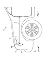
- FIG 1 schematically illustrates a soft-nose vehicle 2 comprising a bonnet latch bracket arrangement 4 according to a first embodiment of the invention.
- the vehicle 2 comprises an openable bonnet 6, a grille 8 and a soft nose panel 9, which meets the bonnet 6 at a front edge 6a of the bonnet 6.
- the bonnet latch bracket arrangement 4 comprises a cross member 10 (not visible in Figure 1 , but in Figure 2 ), which forms part of the vehicle body, two bonnet latches 12, located adjacent to each lateral edge of the bonnet 6 and two bracket members 14, located at the ends of the cross member 10.
- Each bonnet latch 12 is attached to the cross member 10 by means of the bracket member 14.
- the bonnet latch 12 is adapted to receive a striker 13 comprised in the bonnet 6 to be able to hold the bonnet 6 in a closed state.
- the bracket member 14 is adapted to take up dimensional differences between the bonnet latch 12 and the cross member 10 in a longitudinal x, a lateral y and/or a height direction z of the vehicle 2. Further, each bracket member 12 is attached to a side beam 11, which also forms part of the vehicle body and which is located at a lateral side of the vehicle 2.
- FIG 2 illustrates the bonnet latch bracket arrangement 4 of Figure 1 in greater detail in a perspective view.
- the bracket member 14 comprises a framework structure and is suitably made of extruded aluminium.
- the bracket member 14 is adapted to collapse when impacted by a force above a predefined level, which is lower than a level of a force needed to collapse the bonnet latch 12 and/or the cross member 10. Thereby the bracket member 14 will collapse before the bonnet latch 12 and/or the cross member 10 in case of a frontal collision or a collision at least partly acting on the front of the vehicle 2. Therefore, if the collision is not too severe, it may be enough to only replace the bracket member 14, instead of having to replace the whole bonnet latch bracket arrangement 2, which is the case for known prior art solutions.
- the framework of the bracket member 14 is designed such that the bracket member 14 has a preferred collapse direction being substantially in the longitudinal direction x of the vehicle 2, while the bracket member 14 is able to withstand a higher force in the z-direction.
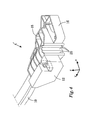
- FIGs 3 and 4 schematically illustrate a standard-nose vehicle 2' comprising a bonnet latch bracket arrangement 4' according to a second embodiment of the invention.
- the standard-nose vehicle 2' comprises an openable bonnet 6' and a grille 8', which meets the bonnet 6' in a more forward position of the vehicle 2 as compared to Figure 1 .
- the bonnet latch bracket arrangement 4' comprises a cross member 10 (not visible in Figure 3 but in Figure 4 , which forms part of the vehicle body, and two bonnet latches 12, located adjacent to each lateral edge of the bonnet 6.
- the cross member 10 is of the same kind as for the soft-nose vehicle 2 of Figures 1 and 2 .
- the bonnet latches 12 are also of the same kind as for the soft-nose vehicle 2 of Figures 1 and 2 .
- the bonnet latch bracket arrangement 4' thus only differs from that of Figures 1 and 2 regarding the bracket member 14'.
- the bracket member 14' of the second embodiment comprises a first bracket member portion 16 similar to the bracket member 14 of Figures 1 and 2 . Located on top of the first bracket member portion 16, there is a second bracket member portion 18. The second bracket member portion 18 displaces the location of the bonnet latch 12 forward in the vehicle 2' by a distance corresponding to the difference between the standard-nose vehicle 2' and the soft-nose vehicle 2.
- Both the first and second bracket member portions 16, 18 comprise framework structure.
- the framework of the second bracket member portion 18 is provided with collapse trigger points 20.
- the collapse of the bracket member 14' will start at one or more of the collapse trigger points 20.
- the second bracket member portion 18 will be compressed in the longitudinal x direction of the vehicle 2.
- the first bracket member portion 16 may collapse as well.
- bracket member As an alternative to using two bracket member portions 16, 18, one bracket member could be used instead, which bracket member is able to take up the dimensional differences between the bonnet latch 12 and the cross member 10 in the longitudinal x, lateral y and/or height direction z of the vehicle 2. It may have the same shape as the combination of the first and second bracket member portions 16, 18 of Figures 3 and 4 .
Landscapes
- Engineering & Computer Science (AREA)
- Structural Engineering (AREA)
- Mechanical Engineering (AREA)
- Superstructure Of Vehicle (AREA)
Abstract
- a bonnet latch (12),
- a bracket member (14, 14'), and
- a vehicle body member (10),
the bonnet latch being attachable to the vehicle body member by means of the bracket member,
the bracket member being adapted to take up dimensional differences between the bonnet latch and the vehicle body member in a longitudinal, lateral and/or height direction of the vehicle, and
the adaptability to different vehicle models being achieved by varying the geometry of the bracket member according to the dimensions of the vehicle model.
Description
- The present disclosure relates to a bonnet latch bracket arrangement, as well as to a bracket member and a second bracket member portion used in the bonnet latch bracket arrangement. The disclosure further relates to a modular system for configuration of a bonnet latch bracket arrangement to different vehicle models and a method for adapting a bonnet latch bracket arrangement to fit in different vehicle models.
- A vehicle, such as a car, normally comprises a bonnet which is openable in order to allow access to the engine compartment, e.g. for maintenance. At the front of the vehicle there is one or more bonnet latches for locking the openable bonnet in a closed state. The bonnet latch connects the bonnet to the vehicle body when in the closed state. The location of the bonnet latch/es is/are preferably adapted to the dimensions of the vehicle model. If using one bonnet latch, it is usually placed at a location corresponding to the centre of a front region of the bonnet. If two bonnet latches are used, they are normally located at locations corresponding to the front portion of the lateral edges of the bonnet. It is also possible to use a plurality of bonnet latches, which may be distributed over location corresponding to the front region of the bonnet.
- When the bonnet of the vehicle is closed, it should be securely latched in its closed state in order to prevent the bonnet being opened by relative wind and vibrations during operation of the vehicle. Furthermore, in the event of a collision, the bonnet should be deformed in a predeterminable manner. It is therefore important that the bonnet latch structure is capable of retaining the bonnet in the closed state during the collision.
- The front part of a vehicle may be constructed in different ways. It is known to use a so-called soft-nose configuration. The soft nose is often constructed from a thermoplastic, which partially may serve to mitigate the consequences of a collision with a pedestrian. In a soft-nose vehicle a soft nose panel meets the bonnet of the vehicle at a more rearward position than for a standard-nose vehicle, wherein the bonnet meets the grille at the front of the vehicle.
- Document
EP 2 045 146 A1 discloses a bonnet latch structure for a soft-nose vehicle. The vehicle comprises a soft-nose outer skin panel and a bonnet providing an overlying structure for a grille opening reinforcing front cross member. The front cross member supports at least one bonnet latch carried by a member protruding towards the front of the vehicle. The member is designed to collapse downwards causing the bonnet latch to move downwards when subjected to longitudinal loads above 0.6 kN distributed thereupon by the overlying structure. As a consequence of the collapse, the bonnet latch may move away to provide a forgiving upper leg impact zone for the protection of a pedestrian in the event of a collision with the motor vehicle. - However, a bonnet latch structure according to
EP 2 045 146 A1 has a geometrical shape which is adapted to be used in a certain soft-nose vehicle model. If used in another soft-nose vehicle model, having other geometrical dimensions, the configuration of the bonnet latch structure needs to be changed to fit to the dimensions of that other vehicle model. Furthermore, the configuration of the bonnet latch structure needs further changes in order to fit in a standard-nose vehicle model. Since the change of the configuration comprises changing the shape and the size of the front cross member, it will be quite costly since new tools are needed for manufacturing. - The object of the present disclosure is to overcome or ameliorate at least one of the disadvantages of the prior art, or to provide a useful alternative.
- It is desirable to provide a bonnet latch bracket arrangement, which is adaptable for different vehicle models.
- The object above may be achieved by the subject-matter of claim 1.
- Thus, in a first aspect of the present invention there is provided a bonnet latch bracket arrangement for a vehicle, which arrangement is adaptable to different vehicle models. The arrangement comprises:
- a bonnet latch,
- a bracket member, and
- a vehicle body member.
- The bonnet latch is attachable to the vehicle body member by means of the bracket member. The bracket member is adapted to take up dimensional differences between the bonnet latch and the vehicle body member in a longitudinal, lateral and/or height direction of the vehicle. The adaptability to different vehicle models is achieved by varying the geometry of the bracket member according to the dimensions of the vehicle model.
- If using a bonnet latch bracket arrangement according to the invention, it is possible to easily adapt the bonnet latch bracket arrangement to the actual vehicle model by adapting the geometry of the bracket member. The vehicle body member may be a cross member adapted to be located at the front of the vehicle. This means that the same kind of vehicle body member and bonnet latch may be used for different vehicle models. Thereby the manufacturing cost and/or storage cost for the vehicle body member and/or the bracket member will be reduced as compared to conventional technology using a vehicle body member and a bracket member adapted to the specific vehicle model. At a workshop, fewer spare parts are needed.
- The bonnet latch bracket arrangement may further be adapted to different crash scenarios by adapting the bracket member. The same kind of vehicle body member and bonnet latch may then be used for different crash scenarios.
- A first of the different vehicle models may be a soft-nose vehicle and a second of the different vehicle models may be a standard-nose vehicle. As is known by the skilled person, a soft nose panel meets the bonnet of the vehicle at a more rearward position than in a "standard-nose vehicle, wherein the bonnet meets the grille at the front of the vehicle. However, according to the invention, the bonnet latch and the vehicle body member can have the same geometry for the soft-nose and standard-nose vehicle models, since the adaptability to the first and the second vehicle models is achieved by varying the geometry of the bracket member.
- One, two or more bonnet latches may be used. The may each have a corresponding bracket member. However, if two of the bonnet latches are located close to each other, they may share a bracket member. If two bonnet latches are used, they are normally located at locations corresponding to the front portion of the lateral edges of the bonnet. There is then suitably one bracket member at each side for each of the bonnet latches.
- The bracket member may comprise a sleeve portion enclosing a portion of the vehicle body member. The sleeve portion is preferably adapted to be welded to or heat shrunk to the vehicle body member. Thereby the bracket member is securely attached to the vehicle body member.
- The bracket member may in addition be adapted to be attached to a side beam of the vehicle.
- The bracket member may be collapsible. It may be adapted to collapse when impacted by a force above a predefined level, the predefined level being lower than a level of a force needed to collapse the bonnet latch and/or the vehicle body member. Thereby the bracket member will collapse first, i.e. before the bonnet latch and/or the cross member in case of a frontal collision or a collision at least partly acting on the front of the vehicle. Therefore, if the collision is not too severe, it may be enough to only replace the bracket member, instead of having to replace the whole bonnet latch bracket arrangement, which is the case for known prior art solutions. This would reduce the cost of the repair. The predefined level may be selected by adapting the shape of the bracket member and/or the material of it.
- In an embodiment, bracket member is configured to collapse in a preferred direction, when mounted in the vehicle, the preferred direction preferably being substantially in a longitudinal direction of the vehicle. The preferred direction thus corresponds to a collision case of a frontal collision or a collision at least partly acting on the front of the vehicle. The bracket member may thus be designed to withstand higher forces in the height direction of the vehicle than in the longitudinal direction of the vehicle.
- The bracket member may comprise a framework structure. The framework structure provides a strong construction, which is not too heavy. By selecting the geometry of the framework, it is for example possible to achieve the above-described preferred direction of collapse.
- The framework structure may comprise a collapse trigger point. The trigger point is for example a relatively weak point of the framework wherein the collapse of the bracket member will start. The location of the trigger point has been chosen to achieve a controlled collapse of the bracket member.
- The bracket member may be made of an extruded material, preferably extruded aluminium. Extrusion is for example a suitable way of manufacturing the above-mentioned framework structure. Alternatively, it may be made of steel. The bonnet latch may be of steel. The vehicle body member may be of steel or aluminium.
- In an embodiment, the bracket member comprises a first bracket member portion and at least one second bracket member portion. The first bracket member portion is adapted to fit in a first vehicle model. The second bracket member portion is adapted to be used in combination with the first bracket member portion in order to fit into a second vehicle model. In this embodiment, the adaptability to different vehicle models is achieved by changing the geometry of the second bracket member portion having the first bracket member portion as a lowest common denominator. Purely as an example, the first bracket member portion may be selected to fit in a soft-nose vehicle. The second bracket member portion is then chosen, such that it takes up the dimensional differences in the longitudinal, lateral and/or height direction between the soft-nose vehicle and a standard-nose vehicle. A third vehicle model may have a third bracket member portion, which may be used in combination with the first bracket member portion or, as an alternative, the first, second and third bracket members may be used in combination.
- In a second aspect of the present invention there is provided a bracket member adapted for use in a bonnet latch bracket as described above.
- In a third aspect of the present invention there is provided a second bracket member portion adapted for use in combination with a first bracket member portion in order to form a bracket member of a bonnet latch bracket arrangement according to above.
- In a fourth aspect of the present invention there is provided a modular system for configuration of a bonnet latch bracket arrangement to different vehicle models, the system comprising:
- a bonnet latch
- a vehicle body member, and
- i bracket member variants i being a positive integer.
- The bonnet latch is attachable to the vehicle body member by means of one of the bracket member variants. The bracket member variant is adapted to take up dimensional differences between the bonnet latch and the vehicle body member in a longitudinal, lateral and/or height direction of the vehicle. Each of the bracket member variants has a geometry adapted to the dimensions of one of the different vehicle models.
- As explained above the bracket member variant may be in one unit. The geometry will then be different between different vehicle models. Alternatively, the changed geometry may be achieved by using a first bracket member portion being common to many vehicle models and using at least one second bracket member portion to achieve the adaptation to the individual vehicle model.
- In a fifth aspect of the present invention there is provided a method for adapting a bonnet latch bracket arrangement to fit in different vehicle models, such as a soft-nose vehicle and a standard-nose vehicle. The bonnet latch bracket arrangement comprises a bonnet latch a bracket member and a vehicle body member. The bonnet latch is attachable to the vehicle body member by means of the bracket member. The bracket member is adapted to take up dimensional differences between the bonnet latch and the vehicle body member in a longitudinal, lateral and/or height direction of the vehicle. The method comprises the step of:
- selecting the geometry of the bracket member while keeping the geometry of the bonnet latch and the vehicle body member, such that the bracket member fits the geometry of the vehicle model.
- In a sixth aspect of the present invention there is provided a vehicle comprising a bracket member, a second bracket member portion and/or a bonnet latch bracket arrangement according to above.
- The present invention will hereinafter be further explained by means of non-limiting examples with reference to the appended drawings wherein:
- Fig. 1
- illustrates a soft-nose vehicle comprising a bonnet latch bracket arrangement according to a first embodiment of the invention,
- Fig. 2
- illustrates a detail of the bonnet latch bracket arrangement of
Fig. 1 ; - Fig. 3
- illustrates a standard-nose vehicle comprising a bonnet latch bracket arrangement according to a second embodiment of the invention, and
- Fig. 4
- illustrates a detail of the bonnet latch bracket arrangement of
Fig. 3 ; - It should be noted that the appended drawings are not necessarily drawn to scale and that the dimensions of some features of the present invention may have been exaggerated for the sake of clarity.
- The invention will, in the following, be exemplified by embodiments. It should however be realized that the embodiments are included in order to explain principles of the invention and not to limit the scope of the invention, defined by the appended claims. Details from two or more of the embodiments may be combined with each other.
-
Figure 1 schematically illustrates a soft-nose vehicle 2 comprising a bonnetlatch bracket arrangement 4 according to a first embodiment of the invention. The vehicle 2 comprises an openable bonnet 6, agrille 8 and a soft nose panel 9, which meets the bonnet 6 at a front edge 6a of the bonnet 6. The bonnetlatch bracket arrangement 4 comprises a cross member 10 (not visible inFigure 1 , but inFigure 2 ), which forms part of the vehicle body, two bonnet latches 12, located adjacent to each lateral edge of the bonnet 6 and twobracket members 14, located at the ends of thecross member 10. Eachbonnet latch 12 is attached to thecross member 10 by means of thebracket member 14. Thebonnet latch 12 is adapted to receive a striker 13 comprised in the bonnet 6 to be able to hold the bonnet 6 in a closed state. Thebracket member 14 is adapted to take up dimensional differences between thebonnet latch 12 and thecross member 10 in a longitudinal x, a lateral y and/or a height direction z of the vehicle 2. Further, eachbracket member 12 is attached to aside beam 11, which also forms part of the vehicle body and which is located at a lateral side of the vehicle 2. -
Figure 2 illustrates the bonnetlatch bracket arrangement 4 ofFigure 1 in greater detail in a perspective view. Thebracket member 14 comprises a framework structure and is suitably made of extruded aluminium. Thebracket member 14 is adapted to collapse when impacted by a force above a predefined level, which is lower than a level of a force needed to collapse thebonnet latch 12 and/or thecross member 10. Thereby thebracket member 14 will collapse before thebonnet latch 12 and/or thecross member 10 in case of a frontal collision or a collision at least partly acting on the front of the vehicle 2. Therefore, if the collision is not too severe, it may be enough to only replace thebracket member 14, instead of having to replace the whole bonnet latch bracket arrangement 2, which is the case for known prior art solutions. - The framework of the
bracket member 14 is designed such that thebracket member 14 has a preferred collapse direction being substantially in the longitudinal direction x of the vehicle 2, while thebracket member 14 is able to withstand a higher force in the z-direction. -
Figures 3 and4 schematically illustrate a standard-nose vehicle 2' comprising a bonnet latch bracket arrangement 4' according to a second embodiment of the invention. The standard-nose vehicle 2' comprises an openable bonnet 6' and a grille 8', which meets the bonnet 6' in a more forward position of the vehicle 2 as compared toFigure 1 . The bonnet latch bracket arrangement 4' comprises a cross member 10 (not visible inFigure 3 but inFigure 4 , which forms part of the vehicle body, and two bonnet latches 12, located adjacent to each lateral edge of the bonnet 6. - The
cross member 10 is of the same kind as for the soft-nose vehicle 2 ofFigures 1 and2 . Further, the bonnet latches 12 are also of the same kind as for the soft-nose vehicle 2 ofFigures 1 and2 . The bonnet latch bracket arrangement 4' thus only differs from that ofFigures 1 and2 regarding the bracket member 14'. The bracket member 14' of the second embodiment comprises a firstbracket member portion 16 similar to thebracket member 14 ofFigures 1 and2 . Located on top of the firstbracket member portion 16, there is a secondbracket member portion 18. The secondbracket member portion 18 displaces the location of thebonnet latch 12 forward in the vehicle 2' by a distance corresponding to the difference between the standard-nose vehicle 2' and the soft-nose vehicle 2. - Both the first and second
bracket member portions bracket member portion 18 is provided with collapse trigger points 20. In case the bonnet latch bracket arrangement 4' is exerted to a longitudinal force, the collapse of the bracket member 14' will start at one or more of the collapse trigger points 20. The secondbracket member portion 18 will be compressed in the longitudinal x direction of the vehicle 2. Depending on the size of the force, the firstbracket member portion 16 may collapse as well. - As an alternative to using two
bracket member portions bonnet latch 12 and thecross member 10 in the longitudinal x, lateral y and/or height direction z of the vehicle 2. It may have the same shape as the combination of the first and secondbracket member portions Figures 3 and4 . - Further modifications of the invention within the scope of the appended claims are feasible. As such, the present invention should not be considered as limited by the embodiments and figures described herein. Rather, the full scope of the invention should be determined by the appended claims, with reference to the description and drawings.
Claims (15)
- A bonnet latch bracket arrangement (4, 4') for a vehicle (2, 2'), which arrangement (4, 4') is adaptable to different vehicle models, said arrangement (4, 4') comprising- a bonnet latch (12),- a bracket member (14, 14'), and- a vehicle body member (10),said bonnet latch (12) being attachable to said vehicle body member (10) by means of said bracket member (14, 14'),
said bracket member (14, 14') being adapted to take up dimensional differences between said bonnet latch (12) and said vehicle body member (10) in a longitudinal (x), lateral (y) and/or height (z) direction of said vehicle (2, 2'), and said adaptability to different vehicle models being achieved by varying the geometry of said bracket member (14, 14') according to the dimensions of the vehicle model. - The bonnet latch bracket arrangement (4, 4') according to claim 1, wherein a first of said different vehicle models is a soft-nose vehicle (2) and a second of said different vehicle models is a standard-nose vehicle (2'),
said bonnet latch (12) and said vehicle body member (10) having the same geometry for said first and second vehicle models, and said adaptability to said first and said second vehicle models being achieved by varying the geometry of said bracket member (14, 14'). - The bonnet latch bracket arrangement (4, 4') according to any one of the preceding claims, wherein said bracket member (14, 14') comprises a sleeve portion enclosing a portion of said vehicle body member (10), said sleeve portion preferably being adapted to be welded to or heat shrunk to said vehicle body member (10).
- The bonnet latch bracket arrangement (4, 4') according to any one of the preceding claims, wherein said vehicle body member (10) is a cross member adapted to be located at the front of said vehicle.
- The bonnet latch bracket arrangement (4, 4') according to any one of the preceding claims, wherein said bracket member (14, 14') in addition is adapted to be attached to a side beam (11) of said vehicle.
- The bonnet latch bracket arrangement (4, 4') according to any one of the preceding claims, wherein said bracket member (14, 14') is adapted to collapse when impacted by a force above a predefined level, said predefined level being lower than a level of a force needed to collapse said bonnet latch (12) and/or said vehicle body member (10).
- The bonnet latch bracket arrangement (4, 4') according to any one of the preceding claims, wherein said bracket member (14, 14') is configured to collapse in a preferred direction, when mounted in said vehicle (2, 2'), said preferred direction preferably being substantially in a longitudinal direction of said vehicle (2, 2').
- The bonnet latch bracket arrangement (4, 4') according to any one of the preceding claims, wherein said bracket member (14, 14') comprises a framework structure.
- The bonnet latch bracket arrangement (4, 4') according to claim 8, wherein said framework structure comprises a collapse trigger point (20).
- The bonnet latch bracket arrangement (4, 4') according to any one of the preceding claims, wherein said bracket member (14, 14') is made of an extruded material, preferably extruded aluminium.
- The bonnet latch bracket arrangement (4') according to any one of the preceding claims, wherein said bracket member (14') comprises a first (16) and at least one second bracket member portion (18), whereof said first bracket member portion (16) is adapted to fit in a first vehicle model and said second bracket member portion (18) is adapted to be used in combination with said first bracket member portion (16) in order to fit into a second vehicle model.
- A bracket member (14, 14') adapted for use in a bonnet latch bracket arrangement (4, 4') according to any one of the preceding claims.
- A second bracket member portion (18) adapted for use in combination with a first bracket member portion (16) in order to form a bracket member (14') of a bonnet latch bracket arrangement (4') according to claim 11.
- A modular system for configuration of a bonnet latch bracket arrangement (4') to different vehicle models, said system comprising- a bonnet latch (12),- a vehicle body member (10), and- i bracket member variants (14, 14'), i being a positive integer,
said bonnet latch (12) being attachable to said vehicle body member (10) by means of one of said bracket member variants (14, 14'),
said bracket member variant (14, 14') being adapted to take up dimensional differences between said bonnet latch (12) and said vehicle body member (10) in a longitudinal (x), lateral (y) and/or height (z) direction of said vehicle,
each of said bracket member variants (14, 14') having a geometry adapted to the dimensions of one of said different vehicle models. - A method for adapting a bonnet latch bracket arrangement (4, 4') to fit in different vehicle models, such as a soft-nose vehicle (2) and a standard-nose vehicle (2'), said bonnet latch bracket arrangement (4, 4') comprising a bonnet latch (12), a bracket member (14, 14') and a vehicle body member (10),
said bonnet latch (12) being attachable to said vehicle body member (10) by means of said bracket member (14, 14'),
said bracket member (14, 14') being adapted to take up dimensional differences between said bonnet latch (12) and said vehicle body member (10) in a longitudinal (x), lateral (y) and/or height (z) direction of said vehicle said method comprising the step of- selecting the geometry of said bracket member (14, 14') while keeping the geometry of said bonnet latch (12) and said vehicle body member (10), such that said bracket member (14, 14') fits the geometry of said vehicle model.
Priority Applications (3)
| Application Number | Priority Date | Filing Date | Title |
|---|---|---|---|
| EP12174691.1A EP2682312B1 (en) | 2012-07-03 | 2012-07-03 | Bonnet latch bracket arrangement |
| CN201310274577.7A CN103523097B (en) | 2012-07-03 | 2013-07-02 | Bonnet latch bracket arrangement |
| US13/934,077 US9689181B2 (en) | 2012-07-03 | 2013-07-02 | Bonnet latch bracket arrangement |
Applications Claiming Priority (1)
| Application Number | Priority Date | Filing Date | Title |
|---|---|---|---|
| EP12174691.1A EP2682312B1 (en) | 2012-07-03 | 2012-07-03 | Bonnet latch bracket arrangement |
Publications (2)
| Publication Number | Publication Date |
|---|---|
| EP2682312A1 true EP2682312A1 (en) | 2014-01-08 |
| EP2682312B1 EP2682312B1 (en) | 2019-03-27 |
Family
ID=46456402
Family Applications (1)
| Application Number | Title | Priority Date | Filing Date |
|---|---|---|---|
| EP12174691.1A Active EP2682312B1 (en) | 2012-07-03 | 2012-07-03 | Bonnet latch bracket arrangement |
Country Status (3)
| Country | Link |
|---|---|
| US (1) | US9689181B2 (en) |
| EP (1) | EP2682312B1 (en) |
| CN (1) | CN103523097B (en) |
Families Citing this family (1)
| Publication number | Priority date | Publication date | Assignee | Title |
|---|---|---|---|---|
| CN113859366B (en) * | 2021-10-29 | 2023-01-24 | 岚图汽车科技有限公司 | Universal front-end module, engine room assembly and automobile |
Citations (5)
| Publication number | Priority date | Publication date | Assignee | Title |
|---|---|---|---|---|
| DE10308371A1 (en) * | 2003-02-27 | 2004-09-16 | Daimlerchrysler Ag | Lock for motor vehicle bonnet has lock keeper attached to bonnet lid by deformable section to reduce impact with pedestrian in case of accident |
| DE102007034556A1 (en) * | 2007-07-25 | 2009-01-29 | Audi Ag | Locking device for the front flap of a motor vehicle |
| EP2045146A1 (en) | 2007-10-03 | 2009-04-08 | Ford Global Technologies, LLC | Pedestrian Safety Bonnet Latch Structure for a Motor Vehicle |
| DE102008039731A1 (en) * | 2008-08-26 | 2010-03-04 | Bayerische Motoren Werke Aktiengesellschaft | Bonnet i.e. front bonnet, locking apparatus for passenger car, has additional locking device with locking bolt and locking hook, which are movable from original to locked position and hold closing bracket against opening in locked position |
| EP2374665A1 (en) * | 2010-04-07 | 2011-10-12 | Honda Motor Co., Ltd. | Pedestrian protection device for vehicle |
Family Cites Families (10)
| Publication number | Priority date | Publication date | Assignee | Title |
|---|---|---|---|---|
| GB741888A (en) * | 1953-05-15 | 1955-12-14 | Amal Ltd | Improvements in or relating to motor vehicle bonnet fasteners |
| US2793061A (en) * | 1955-01-07 | 1957-05-21 | Atwood Vacuum Machine Co | Hood latch structure |
| US3397906A (en) * | 1965-10-15 | 1968-08-20 | Modern Metal Products Co | Hood and deck latch |
| US3974753A (en) * | 1975-03-10 | 1976-08-17 | Lois Loreen Sanchez | Automobile roof vent |
| US6014876A (en) * | 1999-01-04 | 2000-01-18 | Ford Global Technologies, Inc. | Adjustable locking for hood latch |
| US6280592B1 (en) * | 1999-07-02 | 2001-08-28 | Ford Global Technologies, Inc. | Resin-bonded solid-film-lubricant coated hood latch mechanism and method of making |
| US20060170224A1 (en) * | 2003-02-21 | 2006-08-03 | Mitchell John R S | Hood latch assembly |
| DE102009056415A1 (en) * | 2009-12-01 | 2011-06-09 | Hbpo Gmbh | Motor vehicle front end assembly for installing lock for bonnet, has plate with fastening regions arranged with directional component in direction and in transverse direction, where direction is extended perpendicular to driving direction |
| CN103608247B (en) * | 2011-05-23 | 2016-08-17 | 马自达汽车株式会社 | Front body structure of the vehicle |
| US9222288B2 (en) * | 2012-09-01 | 2015-12-29 | GM Global Technology Operations LLC | Integrated hood latch keeper for a grill opening reinforcement structure |
-
2012
- 2012-07-03 EP EP12174691.1A patent/EP2682312B1/en active Active
-
2013
- 2013-07-02 CN CN201310274577.7A patent/CN103523097B/en active Active
- 2013-07-02 US US13/934,077 patent/US9689181B2/en active Active
Patent Citations (5)
| Publication number | Priority date | Publication date | Assignee | Title |
|---|---|---|---|---|
| DE10308371A1 (en) * | 2003-02-27 | 2004-09-16 | Daimlerchrysler Ag | Lock for motor vehicle bonnet has lock keeper attached to bonnet lid by deformable section to reduce impact with pedestrian in case of accident |
| DE102007034556A1 (en) * | 2007-07-25 | 2009-01-29 | Audi Ag | Locking device for the front flap of a motor vehicle |
| EP2045146A1 (en) | 2007-10-03 | 2009-04-08 | Ford Global Technologies, LLC | Pedestrian Safety Bonnet Latch Structure for a Motor Vehicle |
| DE102008039731A1 (en) * | 2008-08-26 | 2010-03-04 | Bayerische Motoren Werke Aktiengesellschaft | Bonnet i.e. front bonnet, locking apparatus for passenger car, has additional locking device with locking bolt and locking hook, which are movable from original to locked position and hold closing bracket against opening in locked position |
| EP2374665A1 (en) * | 2010-04-07 | 2011-10-12 | Honda Motor Co., Ltd. | Pedestrian protection device for vehicle |
Also Published As
| Publication number | Publication date |
|---|---|
| US9689181B2 (en) | 2017-06-27 |
| CN103523097A (en) | 2014-01-22 |
| CN103523097B (en) | 2018-03-30 |
| US20140008502A1 (en) | 2014-01-09 |
| EP2682312B1 (en) | 2019-03-27 |
Similar Documents
| Publication | Publication Date | Title |
|---|---|---|
| JP4407755B2 (en) | Vehicle hood structure | |
| US7597384B2 (en) | Engine compartment hood latch structure for a motor vehicle | |
| EP2033855B1 (en) | Pedestrian Safety Structure for a Motor Vehicle Body | |
| JP7135275B2 (en) | Vehicle structural member | |
| JP7135274B2 (en) | Vehicle structural member | |
| JP2013521194A (en) | Bonnet energy absorber for pedestrians | |
| US8733485B2 (en) | Front module for a motor vehicle | |
| JP2007038839A (en) | Rear body structure of automobile | |
| EP2657108B1 (en) | Hinge and support member arrangement | |
| CN100377925C (en) | System for preventing window from protruding into railway vehicle cab during impact | |
| EP2572941B1 (en) | Crush box and vehicle bumper apparatus including the same | |
| US20200262371A1 (en) | Bumper for a vehicle | |
| EP1842746B1 (en) | A bonnet for a vehicle | |
| US9340171B2 (en) | Deformation element, in particular for bumpers on motor vehicles | |
| CN107031724B (en) | Chassis-subframe arrangement for improved crash protection | |
| US9689181B2 (en) | Bonnet latch bracket arrangement | |
| CN204488630U (en) | Motor vehicle headlamp assembly and the headlight module for power actuated vehicle | |
| JP2008120256A (en) | Shock absorption structure for vehicles | |
| US9637077B2 (en) | Frontal impact energy absorption members | |
| RU2648915C2 (en) | Folding vehicle hood | |
| CN101274610A (en) | Front underrun protection device of extended type for industrial or commercial vehicle | |
| EP3722185B1 (en) | Lateral push element | |
| EP3184375B1 (en) | Hinge arrangement | |
| CN105015452A (en) | Mounting structure of automobile storage battery | |
| ES2595052T3 (en) | Load stop system for motor vehicles |
Legal Events
| Date | Code | Title | Description |
|---|---|---|---|
| PUAI | Public reference made under article 153(3) epc to a published international application that has entered the european phase |
Free format text: ORIGINAL CODE: 0009012 |
|
| AK | Designated contracting states |
Kind code of ref document: A1 Designated state(s): AL AT BE BG CH CY CZ DE DK EE ES FI FR GB GR HR HU IE IS IT LI LT LU LV MC MK MT NL NO PL PT RO RS SE SI SK SM TR |
|
| AX | Request for extension of the european patent |
Extension state: BA ME |
|
| 17P | Request for examination filed |
Effective date: 20140708 |
|
| RBV | Designated contracting states (corrected) |
Designated state(s): AL AT BE BG CH CY CZ DE DK EE ES FI FR GB GR HR HU IE IS IT LI LT LU LV MC MK MT NL NO PL PT RO RS SE SI SK SM TR |
|
| 17Q | First examination report despatched |
Effective date: 20150325 |
|
| STAA | Information on the status of an ep patent application or granted ep patent |
Free format text: STATUS: EXAMINATION IS IN PROGRESS |
|
| GRAP | Despatch of communication of intention to grant a patent |
Free format text: ORIGINAL CODE: EPIDOSNIGR1 |
|
| STAA | Information on the status of an ep patent application or granted ep patent |
Free format text: STATUS: GRANT OF PATENT IS INTENDED |
|
| INTG | Intention to grant announced |
Effective date: 20181017 |
|
| GRAS | Grant fee paid |
Free format text: ORIGINAL CODE: EPIDOSNIGR3 |
|
| GRAA | (expected) grant |
Free format text: ORIGINAL CODE: 0009210 |
|
| STAA | Information on the status of an ep patent application or granted ep patent |
Free format text: STATUS: THE PATENT HAS BEEN GRANTED |
|
| AK | Designated contracting states |
Kind code of ref document: B1 Designated state(s): AL AT BE BG CH CY CZ DE DK EE ES FI FR GB GR HR HU IE IS IT LI LT LU LV MC MK MT NL NO PL PT RO RS SE SI SK SM TR |
|
| REG | Reference to a national code |
Ref country code: GB Ref legal event code: FG4D |
|
| REG | Reference to a national code |
Ref country code: CH Ref legal event code: EP |
|
| REG | Reference to a national code |
Ref country code: AT Ref legal event code: REF Ref document number: 1112670 Country of ref document: AT Kind code of ref document: T Effective date: 20190415 |
|
| REG | Reference to a national code |
Ref country code: IE Ref legal event code: FG4D |
|
| REG | Reference to a national code |
Ref country code: DE Ref legal event code: R096 Ref document number: 602012058210 Country of ref document: DE |
|
| PG25 | Lapsed in a contracting state [announced via postgrant information from national office to epo] |
Ref country code: SE Free format text: LAPSE BECAUSE OF FAILURE TO SUBMIT A TRANSLATION OF THE DESCRIPTION OR TO PAY THE FEE WITHIN THE PRESCRIBED TIME-LIMIT Effective date: 20190327 Ref country code: LT Free format text: LAPSE BECAUSE OF FAILURE TO SUBMIT A TRANSLATION OF THE DESCRIPTION OR TO PAY THE FEE WITHIN THE PRESCRIBED TIME-LIMIT Effective date: 20190327 Ref country code: NO Free format text: LAPSE BECAUSE OF FAILURE TO SUBMIT A TRANSLATION OF THE DESCRIPTION OR TO PAY THE FEE WITHIN THE PRESCRIBED TIME-LIMIT Effective date: 20190627 Ref country code: FI Free format text: LAPSE BECAUSE OF FAILURE TO SUBMIT A TRANSLATION OF THE DESCRIPTION OR TO PAY THE FEE WITHIN THE PRESCRIBED TIME-LIMIT Effective date: 20190327 |
|
| REG | Reference to a national code |
Ref country code: NL Ref legal event code: MP Effective date: 20190327 |
|
| PG25 | Lapsed in a contracting state [announced via postgrant information from national office to epo] |
Ref country code: GR Free format text: LAPSE BECAUSE OF FAILURE TO SUBMIT A TRANSLATION OF THE DESCRIPTION OR TO PAY THE FEE WITHIN THE PRESCRIBED TIME-LIMIT Effective date: 20190628 Ref country code: RS Free format text: LAPSE BECAUSE OF FAILURE TO SUBMIT A TRANSLATION OF THE DESCRIPTION OR TO PAY THE FEE WITHIN THE PRESCRIBED TIME-LIMIT Effective date: 20190327 Ref country code: BG Free format text: LAPSE BECAUSE OF FAILURE TO SUBMIT A TRANSLATION OF THE DESCRIPTION OR TO PAY THE FEE WITHIN THE PRESCRIBED TIME-LIMIT Effective date: 20190627 Ref country code: LV Free format text: LAPSE BECAUSE OF FAILURE TO SUBMIT A TRANSLATION OF THE DESCRIPTION OR TO PAY THE FEE WITHIN THE PRESCRIBED TIME-LIMIT Effective date: 20190327 Ref country code: NL Free format text: LAPSE BECAUSE OF FAILURE TO SUBMIT A TRANSLATION OF THE DESCRIPTION OR TO PAY THE FEE WITHIN THE PRESCRIBED TIME-LIMIT Effective date: 20190327 Ref country code: HR Free format text: LAPSE BECAUSE OF FAILURE TO SUBMIT A TRANSLATION OF THE DESCRIPTION OR TO PAY THE FEE WITHIN THE PRESCRIBED TIME-LIMIT Effective date: 20190327 |
|
| REG | Reference to a national code |
Ref country code: AT Ref legal event code: MK05 Ref document number: 1112670 Country of ref document: AT Kind code of ref document: T Effective date: 20190327 |
|
| PG25 | Lapsed in a contracting state [announced via postgrant information from national office to epo] |
Ref country code: CZ Free format text: LAPSE BECAUSE OF FAILURE TO SUBMIT A TRANSLATION OF THE DESCRIPTION OR TO PAY THE FEE WITHIN THE PRESCRIBED TIME-LIMIT Effective date: 20190327 Ref country code: PT Free format text: LAPSE BECAUSE OF FAILURE TO SUBMIT A TRANSLATION OF THE DESCRIPTION OR TO PAY THE FEE WITHIN THE PRESCRIBED TIME-LIMIT Effective date: 20190727 Ref country code: AL Free format text: LAPSE BECAUSE OF FAILURE TO SUBMIT A TRANSLATION OF THE DESCRIPTION OR TO PAY THE FEE WITHIN THE PRESCRIBED TIME-LIMIT Effective date: 20190327 Ref country code: SK Free format text: LAPSE BECAUSE OF FAILURE TO SUBMIT A TRANSLATION OF THE DESCRIPTION OR TO PAY THE FEE WITHIN THE PRESCRIBED TIME-LIMIT Effective date: 20190327 Ref country code: ES Free format text: LAPSE BECAUSE OF FAILURE TO SUBMIT A TRANSLATION OF THE DESCRIPTION OR TO PAY THE FEE WITHIN THE PRESCRIBED TIME-LIMIT Effective date: 20190327 Ref country code: RO Free format text: LAPSE BECAUSE OF FAILURE TO SUBMIT A TRANSLATION OF THE DESCRIPTION OR TO PAY THE FEE WITHIN THE PRESCRIBED TIME-LIMIT Effective date: 20190327 Ref country code: EE Free format text: LAPSE BECAUSE OF FAILURE TO SUBMIT A TRANSLATION OF THE DESCRIPTION OR TO PAY THE FEE WITHIN THE PRESCRIBED TIME-LIMIT Effective date: 20190327 |
|
| PG25 | Lapsed in a contracting state [announced via postgrant information from national office to epo] |
Ref country code: SM Free format text: LAPSE BECAUSE OF FAILURE TO SUBMIT A TRANSLATION OF THE DESCRIPTION OR TO PAY THE FEE WITHIN THE PRESCRIBED TIME-LIMIT Effective date: 20190327 Ref country code: PL Free format text: LAPSE BECAUSE OF FAILURE TO SUBMIT A TRANSLATION OF THE DESCRIPTION OR TO PAY THE FEE WITHIN THE PRESCRIBED TIME-LIMIT Effective date: 20190327 |
|
| PG25 | Lapsed in a contracting state [announced via postgrant information from national office to epo] |
Ref country code: IS Free format text: LAPSE BECAUSE OF FAILURE TO SUBMIT A TRANSLATION OF THE DESCRIPTION OR TO PAY THE FEE WITHIN THE PRESCRIBED TIME-LIMIT Effective date: 20190727 Ref country code: AT Free format text: LAPSE BECAUSE OF FAILURE TO SUBMIT A TRANSLATION OF THE DESCRIPTION OR TO PAY THE FEE WITHIN THE PRESCRIBED TIME-LIMIT Effective date: 20190327 |
|
| REG | Reference to a national code |
Ref country code: DE Ref legal event code: R097 Ref document number: 602012058210 Country of ref document: DE |
|
| PG25 | Lapsed in a contracting state [announced via postgrant information from national office to epo] |
Ref country code: DK Free format text: LAPSE BECAUSE OF FAILURE TO SUBMIT A TRANSLATION OF THE DESCRIPTION OR TO PAY THE FEE WITHIN THE PRESCRIBED TIME-LIMIT Effective date: 20190327 |
|
| PLBE | No opposition filed within time limit |
Free format text: ORIGINAL CODE: 0009261 |
|
| STAA | Information on the status of an ep patent application or granted ep patent |
Free format text: STATUS: NO OPPOSITION FILED WITHIN TIME LIMIT |
|
| PG25 | Lapsed in a contracting state [announced via postgrant information from national office to epo] |
Ref country code: SI Free format text: LAPSE BECAUSE OF FAILURE TO SUBMIT A TRANSLATION OF THE DESCRIPTION OR TO PAY THE FEE WITHIN THE PRESCRIBED TIME-LIMIT Effective date: 20190327 Ref country code: MC Free format text: LAPSE BECAUSE OF FAILURE TO SUBMIT A TRANSLATION OF THE DESCRIPTION OR TO PAY THE FEE WITHIN THE PRESCRIBED TIME-LIMIT Effective date: 20190327 |
|
| REG | Reference to a national code |
Ref country code: CH Ref legal event code: PL |
|
| 26N | No opposition filed |
Effective date: 20200103 |
|
| GBPC | Gb: european patent ceased through non-payment of renewal fee |
Effective date: 20190703 |
|
| PG25 | Lapsed in a contracting state [announced via postgrant information from national office to epo] |
Ref country code: TR Free format text: LAPSE BECAUSE OF FAILURE TO SUBMIT A TRANSLATION OF THE DESCRIPTION OR TO PAY THE FEE WITHIN THE PRESCRIBED TIME-LIMIT Effective date: 20190327 |
|
| REG | Reference to a national code |
Ref country code: BE Ref legal event code: MM Effective date: 20190731 |
|
| PG25 | Lapsed in a contracting state [announced via postgrant information from national office to epo] |
Ref country code: GB Free format text: LAPSE BECAUSE OF NON-PAYMENT OF DUE FEES Effective date: 20190703 |
|
| PG25 | Lapsed in a contracting state [announced via postgrant information from national office to epo] |
Ref country code: BE Free format text: LAPSE BECAUSE OF NON-PAYMENT OF DUE FEES Effective date: 20190731 Ref country code: CH Free format text: LAPSE BECAUSE OF NON-PAYMENT OF DUE FEES Effective date: 20190731 Ref country code: LI Free format text: LAPSE BECAUSE OF NON-PAYMENT OF DUE FEES Effective date: 20190731 Ref country code: LU Free format text: LAPSE BECAUSE OF NON-PAYMENT OF DUE FEES Effective date: 20190703 |
|
| PG25 | Lapsed in a contracting state [announced via postgrant information from national office to epo] |
Ref country code: IE Free format text: LAPSE BECAUSE OF NON-PAYMENT OF DUE FEES Effective date: 20190703 |
|
| PG25 | Lapsed in a contracting state [announced via postgrant information from national office to epo] |
Ref country code: CY Free format text: LAPSE BECAUSE OF FAILURE TO SUBMIT A TRANSLATION OF THE DESCRIPTION OR TO PAY THE FEE WITHIN THE PRESCRIBED TIME-LIMIT Effective date: 20190327 |
|
| PG25 | Lapsed in a contracting state [announced via postgrant information from national office to epo] |
Ref country code: MT Free format text: LAPSE BECAUSE OF FAILURE TO SUBMIT A TRANSLATION OF THE DESCRIPTION OR TO PAY THE FEE WITHIN THE PRESCRIBED TIME-LIMIT Effective date: 20190327 Ref country code: HU Free format text: LAPSE BECAUSE OF FAILURE TO SUBMIT A TRANSLATION OF THE DESCRIPTION OR TO PAY THE FEE WITHIN THE PRESCRIBED TIME-LIMIT; INVALID AB INITIO Effective date: 20120703 |
|
| PG25 | Lapsed in a contracting state [announced via postgrant information from national office to epo] |
Ref country code: MK Free format text: LAPSE BECAUSE OF FAILURE TO SUBMIT A TRANSLATION OF THE DESCRIPTION OR TO PAY THE FEE WITHIN THE PRESCRIBED TIME-LIMIT Effective date: 20190327 |
|
| P01 | Opt-out of the competence of the unified patent court (upc) registered |
Effective date: 20231212 |
|
| PGFP | Annual fee paid to national office [announced via postgrant information from national office to epo] |
Ref country code: IT Payment date: 20240619 Year of fee payment: 13 |
|
| PGFP | Annual fee paid to national office [announced via postgrant information from national office to epo] |
Ref country code: FR Payment date: 20250620 Year of fee payment: 14 |
|
| PGFP | Annual fee paid to national office [announced via postgrant information from national office to epo] |
Ref country code: DE Payment date: 20250620 Year of fee payment: 14 |