EP2682290A1 - Kupplungspfanne mit Festkörperschmierstoff - Google Patents
Kupplungspfanne mit Festkörperschmierstoff Download PDFInfo
- Publication number
- EP2682290A1 EP2682290A1 EP13171734.0A EP13171734A EP2682290A1 EP 2682290 A1 EP2682290 A1 EP 2682290A1 EP 13171734 A EP13171734 A EP 13171734A EP 2682290 A1 EP2682290 A1 EP 2682290A1
- Authority
- EP
- European Patent Office
- Prior art keywords
- coupling
- ball
- lubricant component
- socket
- solid lubricant
- Prior art date
- Legal status (The legal status is an assumption and is not a legal conclusion. Google has not performed a legal analysis and makes no representation as to the accuracy of the status listed.)
- Granted
Links
Images


Classifications
-
- B—PERFORMING OPERATIONS; TRANSPORTING
- B60—VEHICLES IN GENERAL
- B60D—VEHICLE CONNECTIONS
- B60D1/00—Traction couplings; Hitches; Draw-gear; Towing devices
- B60D1/01—Traction couplings or hitches characterised by their type
- B60D1/06—Ball-and-socket hitches
-
- B—PERFORMING OPERATIONS; TRANSPORTING
- B60—VEHICLES IN GENERAL
- B60D—VEHICLE CONNECTIONS
- B60D1/00—Traction couplings; Hitches; Draw-gear; Towing devices
- B60D1/58—Auxiliary devices
- B60D1/586—Lubrication means
Definitions
- the present invention relates to a coupling socket of a ball coupling according to the preamble of claim 1.
- a coupling socket is designed for coupling with a coupling ball and has for this purpose a concave coupling portion which faces in the coupled state of the coupling socket a convex mating coupling portion of the coupling ball and this in a contact area touched, wherein in the coupling portion of the coupling socket at least one lubrication region is provided, which is designed to receive lubricant.
- the lubricant is a solid lubricant.
- the present invention can also be realized on the complementary to the coupling socket component of a ball coupling, namely on a coupling ball
- the present invention also relates to a coupling ball of a ball coupling according to the preamble of claim 13.
- a coupling ball is designed for coupling with a coupling socket and has for this purpose a convex mating coupling portion which faces a concave coupling portion of the coupling socket in the coupled state of the coupling ball and contacts it in a contact area, wherein in the mating coupling portion of the coupling ball at least one lubrication region is provided, which is designed to receive lubricant in the form of a solid lubricant component.
- the present invention since the present invention may be practiced on each component of a ball coupling on its own, the present invention also relates to a ball coupling according to the preamble of claim 14.
- a generic ball coupling and their generic items: coupling socket and coupling ball, are from the DE 22 35 874 C3 known.
- This document teaches in the ball socket a bearing shell, which may be made of plastic, to be arranged such that when the coupling ball and coupling socket are coupled together, the bearing shell is located between the ball coupling and coupling socket.
- the bearing shell is inserted into the coupling ball receiving cavity of the coupling socket and held there form-fitting manner via a separately formed spring or snap ring.
- the spring ring is inserted into a groove of the integrally formed ball socket in a conventional manner.
- the well-known spring ring is also designed and dimensioned so that it is expanded during insertion of the coupling ball in the coupling socket of this and relaxed after passing the equator of the coupling ball behind this again to a fürgangshack with smaller clear width than the equatorial diameter of the coupling ball.
- Another ball coupling with coupling socket and coupling ball is from the FR 903 599 A known, which was published on 9 October 1945.
- This document discloses the arrangement of a rubber intermediate element on the coupling socket such that the rubber intermediate element is again in the coupled state between coupling socket and coupling ball.
- the rubber intermediate element is held by means of a rivet on the coupling socket.
- a bearing shell made of sheet steel is vulcanized into the rubber intermediate element.
- the rubber intermediate element is approximately cylindrical at its insertion-side longitudinal end and is formed hemispherical at its insertion end opposite the rivet attachment end (abutment end).
- coupling socket and coupling ball are from the DE 201 16 970 U1 known.
- This document discloses a ball coupling, the coupling socket and / or coupling ball is formed in its coupling portion or counter-coupling portion with recessed lubrication pockets, in which grease can be introduced and thus can serve as a grease reservoir.
- the grease can be applied before coupling the coupling socket to the coupling ball by hand or with a suitable tool or it can, as for example from WO-A-2006 122807 is known to be introduced via a provided on the coupling socket or the coupling ball grease nipple in the coupled state of coupling socket and coupling ball in the coupling portion or counter-coupling portion.
- a solid lubricant component is included, which is at least in a reference state with a temperature of 20 ° C, an air pressure of 1 bar and mechanically loaded only by its own weight as a solid, the necessary in particular for lubrication maintenance work a grease-lubricated ball coupling and / or coupling socket and / or coupling ball reduced.
- a solid lubricant component in the at least one lubrication region eliminates frequent refilling or loading of the lubrication region with grease, as was required in the ball coupling of the prior art.
- the solid lubricant component provides a sliding surface on which the mating coupling portion of the coupling ball or the coupling portion of the coupling socket - depending on which component the solid lubricant component is added - in the coupled state of coupling socket and coupling ball in Compared to the direct ungeschm convinced investment engagement of coupling socket and coupling ball with reduced friction can fit slidably without the Gleitstromeingriff promotes or distributes the solid lubricant in the present between the coupling portion and mating coupling gap more or less uncontrolled.
- the lubrication situation created by the at least one solid lubricant component remains essentially unchanged over a long time due to the higher dimensional stability of the solid lubricant component over a long period of time compared with a formless powdered lubricant such as graphite or a pasty or liquid lubricant such as grease or lubricating oil.
- a formless powdered lubricant such as graphite or a pasty or liquid lubricant such as grease or lubricating oil.
- a lubricant used is a solid in the sense of the present application or not
- a reference state of the lubricant with a temperature of 20 ° C, an atmospheric pressure of the normal air atmosphere of 1 bar and be used except by its own weight unloaded lubricant component.
- the lubricant component in the state in question a solid with a predetermined shape, d. H. neither liquid, nor pasty or powdery or even gaseous, then such a lubricant component should be considered as a solid lubricant component within the meaning of the present application.
- a lubricant component is a solid even at higher or lower temperatures or at higher and lower air pressures. This will usually be the case.
- a lubricant component is a solid lubricant component within the meaning of the present application, but the lubricant component in the above defined reference state. In this case, both the temperature of the lubricant component and the temperature of the atmosphere surrounding it are designated by the designated temperature.
- Object of the present invention is to improve the generic ball coupling and / or its relevant components: coupling socket and / or coupling ball, so that the assembly of the solid lubricant component with the same stability of the assembled ball coupling or one of its relevant components compared to the prior art is facilitated.
- This object is achieved according to the present invention to a generic coupling socket and / or a generic coupling ball and / or on a generic ball coupling characterized in that the solid lubricant component is held by positive engagement on the coupling socket or on the coupling ball.
- the solid lubricant component may be inserted into a complementary recess in the coupling portion of the coupling socket or in the counter coupling portion of the coupling ball, wherein preferably the radial thickness of the lubricant component is greater than the radial dimension of the recess, in which it is used to a projection of the contact surface over a adjacent surface of the coupling section or mating coupling section.
- the solid-state lubricant component can be secured in position by positive engagement of a groove in a component made of solid lubricant component and coupling socket or coupling ball with a latching projection formed on the coupling socket or on the coupling ball in the respective other component.
- the shoulder is preferably a shoulder circumscribing the introduction track, so that the largest possible contact surface of the solid lubricant component trailing the heel is provided with the shoulder and so that the rear grip situation is as independent as possible from the circumferential location around the insertion track.
- the shoulder may be the end face of a heel component, such as a piece of pipe, which can be removed along an insertion path from an insertion region of the coupling socket containing the insertion opening.
- a heel component such as a piece of pipe
- the heel component or pipe section can have an external thread, with which it can be screwed into the insertion region of the coupling socket by means of an internal thread provided there and can be unscrewed from this.
- the paragraph described above is part of the previously described groove, which may be formed in the coupling portion or counter-coupling portion.
- the groove or the step preferably run completely around the insertion path continuously, so that as uniform as possible around the circumference of an insertion of the coupling socket or the coupling ball around fixing state can be achieved.
- the locking projection is thus formed on the solid lubricant component, although this need not be so.
- the latching projection may be formed at one end of the solid lubricant component, so that the solid lubricant component terminates at one end with the latching projection.
- the end of the solid lubricant component is preferably that insertion end, through which the coupling ball is inserted, be it to bear the coupling ball on the fixed to the coupling socket solid lubricant component or be it for attachment of the solid lubricant component to the coupling ball.
- the invention is further developed on the basis of its exemplary application to a coupling socket.
- the developments relating to the solid lubricant component are also applicable to a solid lubricant component which is received in a lubrication region of the coupling ball, although the arrangement of the solid lubricant component in the coupling socket is preferred since the solid lubricant component is less exposed in the concave coupling portion of the coupling socket and thus exposed to environmental influences at the convex mating coupling portion of the coupling ball.
- the solid lubricant component can develop its effect as possible, it is advantageous if it has a contact surface on which in the coupled state of coupling socket and coupling ball when arranging the solid lubricant component in the coupling socket, the coupling ball and on which arrangement of the solid lubricant component on the coupling ball, the coupling socket in Investment is.
- the contact surface is curved, particularly curved around two mutually orthogonal spatial axes.
- the contact surface of the solid lubricant component is preferably formed as Kugelkalotten setup. It is a concave Kugelkalotten Operations with arrangement of the solid lubricant component in the coupling socket and a convex Kugelkalotten specifications when arranged on the coupling ball.
- the contact surface of the solid lubricant component protrudes with respect to a surface of the coupling portion adjacent to the solid lubricant component.
- solid-state lubricant component can be glued to this arrangement in the coupling socket.
- the entire coupling section of the coupling socket is formed by the solid lubricant component.
- the entire coupling portion may be formed by the contact surface of the solid lubricant component, which ensures that the contact area between the coupling ball and coupling socket described above is always located in the contact surface of the solid lubricant component.
- the solid lubricant component is advantageously integrally formed, or it is to facilitate its installation on a coupling socket and / or coupling ball each provided exactly a solid lubricant component.
- the coupling socket - or possibly the coupling ball - has a plurality of solid lubricant components, which are provided distributed over the coupling portion and the counter-coupling portion.
- the solid lubricant components can be provided, which can be arranged equidistant around the insertion path in the coupling socket.
- a contact surface of the solid-state lubricant components which is continuous in the coupled state can be ensured in all or at least in most operating situations.
- solid lubricant components may be provided distributed over the coupling portion, in the case of an arrangement of more solid lubricant components, the number of three solid lubricant components is preferred, since these with sufficient coverage of the coupling portion with contact surface of the solid lubricant components the lowest assembly cost when using a Requires a plurality of solid lubricant components.
- “Lubricant” in the context of the present application is any material or combination of materials whose or their intermediate arrangement between coupling ball and coupling socket reduces the friction occurring between these ball coupling components compared to their immediate unlubricated contact.
- a solid lubricant is basically a polymer in question, with partially or highly crystalline polymers are preferred due to their wear resistance.
- polymers having a degree of crystallization of 20 to 95% are preferred.
- the degree of crystallinity is the quotient of the crystalline polymer mass to the total polymer mass.
- polyamide or even more aromatic polyamide is preferred as a solid lubricant.
- polyaramid which is therefore the most preferred solid lubricant in the ball coupling application described here.
- At least partly fluorinated plastics such as polytetrafluoroethylene or polyvinylidene fluoride may also serve as solid lubricant, although their expected service life in the highly stressing coupling operation should be lower than that of the aromatic polyamides or even polyaramides.
- polymers with a molecular weight of more than 500,000 g / mol can also be considered as a solid lubricant.
- Possible examples of use are high-molecular-weight polyethylene (HNPE) or ultra-high-molecular-weight polyethylene (OHM-PE).
- HNPE high-molecular-weight polyethylene
- OOM-PE ultra-high-molecular-weight polyethylene
- Other polyolefins of correspondingly high molecular weight are also suitable.
- solid state lubricants are aliphatic polyethers, such as polyacetal, or aromatic polyethers, such as aromatic polyketone ketones (PEEK).
- Aromatic polyesters such as polyethylene terephthalate, are also suitable as polymeric solid-state lubricants, although all of these in the mechanically particularly stressful operation of a ball coupling, which is used particularly frequently in agricultural vehicles, will have a lower service life than the preferred aromatic polyamides or even polyaramides , All of these polymers may contain fillers that can enhance their lubricity.
- Possible suitable fillers are oils, molybdenum sulfide, graphite, particles and / or fibers of polytetrafluoroethylene, or else strength-enhancing fillers, such as glass.
- An advantage of polymeric solid lubricant components is the material elasticity of the material.
- the solid lubricant component can thus be formed in its final predetermined shape and even without disassembling assembly of the supporting member: coupling socket and / or coupling ball, are arranged by assembly deformation of this.
- the solid-state lubricant component with the locking projection formed thereon can be moved beyond the above-described shoulder by deformation into the coupling socket and / or onto the coupling ball until a final assembly position is reached. Then, when the locking projection facing a groove on the supporting coupling member, the solid lubricant component will relax due to its material elasticity with its locking projection into the groove and thus produce the desired positive locking engagement.
- the locking projection is formed on a coupling member and the associated groove on the solid lubricant component, which is not preferred for the reasons mentioned above, but also from the increased manufacturing cost of a provided in a concave coupling portion locking projection.
- the coupling socket is integrally formed, for example, forged in one piece and comprises in this one-piece state, at least one coupling formation, on which the concave coupling portion is formed and a projecting from the coupling training drawbar section.
- This one-piece design should not rule out that further components are attached to the so-formed one-piece coupling socket, which merely extend the functional scope of the coupling socket, but are not necessary to produce their basic coupling function.
- the assembly of the solid-state lubricant component described above on the coupling socket or on the coupling ball in the case of a solid solid lubricant component can be carried out solely on the basis of the described deformation.
- the assembly can be facilitated by the fact that the solid lubricant component has at least one recess which, starting from an insertion end, through which the coupling ball can be inserted for engagement with the solid lubricant component, extends into the solid lubricant component.
- this at least one recess which is preferably a groove-shaped recess, the force required to deform the solid-state lubricant component when it is arranged on the coupling socket or on the coupling ball can be reduced.
- the preferably groove-shaped recess may be formed as a thin material point, so is particularly preferably formed at least one groove-shaped recess as the solid lubricant component in the thickness direction enforcing slot. Thereby, the solid lubricant component can be sufficiently deformed with so little force for mounting that a tool insert for deformation is not required.
- the force required for deformation during assembly of the solid-state lubricant component on the coupling socket or on the coupling ball depends inter alia on the length of the recess, which has this starting from the insertion end into the solid lubricant component.
- a significant reduction in the force necessary for deformation during assembly can be achieved if the at least one recess extending over at least one fifth of the axial length of the solid lubricant component from the insertion end to the opposite end of the plant.
- the axial length essentially corresponds to the extension length of the solid lubricant component along the insertion path, along which a coupling ball is introduced into the solid lubricant component.
- hemispherical solid lubricant component therefore its axial extent from the insertion end to the end of the system, the radius of the hemispherical concave, the coupling ball receiving cavity of the solid lubricant component.
- the at least one recess extends over at least one third of the axial length of the solid lubricant component from the introduction to the end of the system.
- the at least one recess extends over at least half of the axial length of the solid lubricant component.
- the holding force of the solid lubricant component of coupling socket and coupling ball with the axial length of at least one recess changes, especially with increasing axial length of the recess is smaller, is provided for a secure hold of the solid lubricant component of the coupling socket and coupling ball advantageously that at least a recess extending over not more than three quarters of the axial length of the solid lubricant component from the insertion end to the opposite end of the system.
- the longitudinal end of the at least one cutout which is located far away from the insertion end, is preferably formed rounded in the solid-state lubricant component.
- the at least one recess extends at an angle from the insertion end into the solid lubricant component. However, this is not preferred. For reasons of keeping the coupling section or the mating coupling section clean, it is much more preferable for the at least one recess to extend substantially orthogonally away from the insertion end. In this case, there is the possibility that dissolves in the at least one recess undesirable accumulated dirt and falls out of the recess addition. For the same reason, it is preferred that the at least one recess has a straight course in the surface of the solid lubricant component. A curvature of the surface having at least one recess should play no role in the assessment of the straightness of the recess. Advantageously, therefore, lie a center line of a recess and the insertion path in a common plane.
- the solid lubricant component may have a plurality of recesses, as described above.
- these recesses are provided around the insertion path in the circumferential direction at a distance, particularly preferably with equidistant spacing.
- fins formed from the solid lubricant material which are connected in the manner of a leaf spring at one longitudinal end fixed to the rest of the solid lubricant component and resiliently projecting from this to the insertion end. Due to the preferred equidistant spacing of the recesses in the circumferential direction, it can be ensured that the deformation of each lamella thus formed requires approximately the same amount of force for the same amount of deformation.
- the at least one cutout or the plurality of cutouts intersects the latching projection on the solid lubricant component described above, since the latching projection, as material thickening, gives the solid lubricant component a locally increased rigidity, which additionally increases the force required for mounting deformation.
- the at least one recess or the plurality of recesses preferably intersects the latching projection at a right angle.
- the present invention is illustrated by the example of a coupling socket.
- the present invention may additionally or alternatively be embodied on a coupling ball of a ball coupling.
- a coupling socket generally designated 10.
- the coupling socket which in Fig. 1 is shown in perspective from obliquely below in partial view, first shows a section of a drawbar 12 and a coupling formation 14 of the coupling socket 10 firmly connected to the drawbar 12.
- drawbar 12 and coupling formation 14 are forged from a blank in one piece, in order to achieve the highest possible component strength by the resulting cold deformation.
- the drawbar 12 may be connected in the usual way with a vehicle, usually a trailer vehicle.
- the coupling formation 14 has an insertion opening 16, through which a coupling ball, such as those in Fig. 2b Coupling ball 18 shown along an insertion path E in the insertion K can be inserted.
- the insertion path E which may be a rectilinear or / and a curvilinear path, is assumed in the example shown here for the sake of simplicity as a straight-ahead insertion path E.
- a concave coupling portion 20 is located, which in the coupled state of the coupling socket 10 with a concave counter-coupling portion 22 of the coupling ball 18 (see Fig. 2b ) can be in abutting contact, and this touches in a touch area.
- the contact area may change in its position and / or extent depending on the load case occurring at the coupled ball coupling. For example, in the accelerated traction mode, the contact area may be located closer to the longitudinal end of the coupling section 20 remote from the drawbar, as in FIG Fig. 2a is indicated by the dashed line contact area 24a.
- the contact area may be located closer to the tiller-lengthwise end of the coupling section, as in FIG Fig. 2a is indicated by the dashed line contact area 24b.
- Both contact regions 24a and 24b are preferably mirror-symmetrical to the sectional plane of the longitudinal sectional view of straight ahead driving of the coupled train Fig. 2a ,
- a friction-reducing component 26 is provided, which in the illustrated embodiments extends substantially over the entire coupling portion 20 of the coupling socket 10.
- the friction reducing member 26 which is referred to as a lubricant component due to its friction reducing effect, is in a reference state with a temperature of 20 ° C, an air pressure of one bar and an exclusive mechanical load due to its own weight as a solid of predetermined shape. Therefore, the friction reducing member 26 in the present application is referred to as a solid lubricant component 26.
- the solid-state lubricant component 26 is advantageously a polymer component which, due to the material, is easy to produce in the desired shape.
- a solid lubricant component 26 is formed of aromatic polyamide or even more preferably of polyaramid. At least the contact surface 26a of the solid lubricant component 26 may be formed from the materials mentioned.
- the solid lubricant component 26 is shown as a one-piece component, which advantageously covers the entire concave coupling portion 20.
- the solid-state lubricant component 26 may have an opening 28 to facilitate assembly of the air present during assembly of the solid lubricant component 26 to the coupling formation 14 between the solid lubricant component 26 and the concave surface 30 of the coupling formation 14 an escape opening, so that the solid lubricant component 26 substantially the entire surface of the concave surface 30 of the coupling formation 14 can be mounted adjacent.
- the solid lubricant component rests against the concave wall of the coupling formation 14 with a large part of its outer surface 26b, which is opposite to the contact surface.
- the whole of the contact surface 26a opposite outer surface 26b abuts against the concave surface 30 of the coupling formation 14.
- the opening 28 is preferably provided at the abutment end 29 of the solid lubricant component 26.
- the solid lubricant component 26 is held only positively in the coupling formation 14.
- the coupling formation 14 in the insertion direction K behind the insertion opening 16 have a shoulder 32, which preferably rotates continuously around the insertion path E.
- This shoulder 32 may be part of a groove 34, which also preferably completely revolves around the insertion path E.
- the shoulder 32 or / and the groove 34 to facilitate the assembly of the solid lubricant component 26 in the coupling formation 14 in a plane which is particularly preferably oriented parallel to the insertion opening 16 or orthogonal to the insertion path E.
- a projecting locking projection 36 may be formed, which rotates particularly preferably continuously around the solid lubricant component 26.
- the latching projection 26 is preferably at a proximal end in the mounted state of the solid lubricant component 26 of the insertion opening 16 17 (insertion) of the solid lubricant component 26 is provided.
- the insertion end 17 is the plant end 29 axially, ie with respect to the insertion path E, opposite.
- a cylindrical or generally curved only about a curvature axis region may adjoin the in the installed state of the insertion opening 16 nearest end portion of the solid lubricant component 26, which is located in the insertion direction K even further inside a dome-shaped section, that is to say a section curved around two mutually orthogonal axes of curvature, preferably a spherical cap-shaped section or a section with at least one spherical cap-shaped contact surface 26a.
- an insertion section 38 of the coupling socket 10 or the coupling formation 14 may also be provided, which may preferably be formed with a cylindrical surface and the insertion path E as a cylinder axis to the insertion of the coupling ball 18 in the coupling portion 20 facilitate.
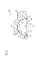
- FIG. 3 a second embodiment of a coupling socket according to the invention is shown.
- the ring member 114 may, as in Fig. 3 is fastened to the coupling formation 114 by fastening means, such as screws 142.
- fastening means such as screws 142.
- the example shown screw 142 is screwed with its screw axis parallel to the insertion path E the ring member 140 penetrating into the coupling formation 114.
- With a larger axial length relative to the insertable E of the ring member 140 may alternatively or additionally to the in Fig. 3 solution also be thought of a radial screwing in fastening screws with respect to the insertion path E.
- a plurality of screws 142 is advantageously provided, of which only one in the cutting plane of Fig. 3 is located.
- the screws 142 are provided in the circumferential direction about the insertion path E equidistant from each other.
- ring member 140 facilitates replacement of the solid lubricant component 126 in case of damage or in case of reaching its service life.
- FIG. 4a another embodiment of a coupling socket according to the present application is shown.
- the view from Fig. 4a corresponds in perspective to that of Fig. 2a .
- Same or functionally identical Components or component sections as in Fig. 2a are in Fig. 4a provided with the same reference numerals, but increased by the number 200.
- the embodiment of the Fig. 4a will be described only insofar as they differ from that of Fig. 2a otherwise, for the explanation of the Fig. 4a is referenced.
- the coupling socket 210 corresponds with respect to the coupling formation 214 and the drawbar 212 completely the coupling socket 10 of Fig. 2a ,
- the embodiment of the Fig. 4a is different from that of Fig. 2a only by the configuration of the solid lubricant component 226. This is provided with at least one recess 250, which will be explained in more detail below.
- the solid-state lubricant component 226 has more than one recess 250 in the illustrated embodiment, although a single recess may already be sufficient to facilitate assembly.
- the solid-state lubricant component 226 has six recesses 250, which are preferably provided equidistantly in the circumferential direction around the insertion path E.
- six recesses 250 are preferably provided equidistantly in the circumferential direction around the insertion path E.
- two, three, four, five or more than six recesses may also be provided.
- the recesses 250 are preferably identical in shape, extension direction and extension length.
- the radial deformation or displacement of the fins 252 requires less force at the same radial deformation amount as the deformation of the recess-free solid lubricant component 26 of the embodiment of FIG Fig. 2a ,
- the recesses 250 extend from the insertion end 227 of the solid lubricant component 226 preferably rectilinearly at right angles into the solid lubricant component 226 in the direction of the abutment end 229 opposite the insertion end 227 with respect to the insertion path E.
- the recess 250 is rectilinear because at the respective local mounting location of the recess 250, there is no axis of curvature orthogonal to the surface 250 of the solid lubricant component 226 having the recess 250 around which the recess 250 is curved.
- the recesses 250 extend over approximately half the axial length of the solid lubricant component between the insertion end 217 and the abutment end 229, as shown. With a length of the recess selected in this way, one for mounting the solid lubricant component 226 on the in Fig. 4a shown integrally formed coupling socket 210 or required at the one-piece coupling training 214 required deformation force so far reduced that it can be effected without tools.
- the fitter can thus elastically deflect the lamellae 252 radially inwardly towards the insertion path E so that the latching projection 36 can be moved past the insertion section 238 until the latching projection 236 can relax into the groove 234 and there the paragraph 236 can fall behind captive.
- the paragraph 232 forms an end face of the groove 234 in the examples shown here.
- the longitudinal end 252a of the recess 250 remote from the insertion end 227 is rounded.
- the at least one recess 250 is formed as the slit passing through the solid lubricant component 226 in the thickness direction so as to reduce as much as possible the force required for the assembly deformation.
- the insertion end 227 of a solid lubricant component 226 has a substantially flat edge, which extends particularly preferably orthogonal to the insertion path E.
- a uniform over the circumference investment condition of a coupling ball to the solid lubricant component 226 can be achieved.
- the latching projection 236 is arranged directly on the insertion end 217.
- the recess 250 intersects the locking projection 236, since the locking projection 236 as material thickening of the solid lubricant component 226 locally increases its rigidity against radial deformation , This increase can be counteracted by a cutting projection intersecting the arrangement of the at least one recess.
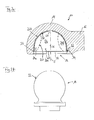
- Fig. 4b is shown as a the solid lubricant component 226 of Fig. 4a corresponding solid lubricant component 226 'is to be attached to a coupling ball 218 in an analogous manner.
- the coupling ball 218 has in an analogous manner with respect to the coupling socket 210 a shoulder 232 ', which is part of a groove 234', which is preferably formed completely circumferentially on the coupling ball 218, preferably at its equator.
- a latching projection 236 'of the solid lubricant component 226' engages in this groove 234 ', wherein this latching projection 236' engages behind the shoulder 232 'in a form-fitting manner.
Landscapes
- Engineering & Computer Science (AREA)
- Transportation (AREA)
- Mechanical Engineering (AREA)
- Pivots And Pivotal Connections (AREA)
- Mechanical Operated Clutches (AREA)
Abstract
Description
- Die vorliegende Erfindung betrifft eine Kupplungspfanne einer Kugelkupplung gemäß dem Oberbegriff von Anspruch 1. Eine solche Kupplungspfanne ist zur Kupplung mit einer Kupplungskugel ausgebildet und weist hierzu einen konkaven Kupplungsabschnitt auf, der im gekuppelten Zustand der Kupplungspfanne einem konvexen Gegenkupplungsabschnitt der Kupplungskugel gegenüberliegt und diesen in einem Berührbereich berührt, wobei im Kupplungsabschnitt der Kupplungspfanne wenigstens ein Schmierungsbereich vorgesehen ist, welcher zur Aufnahme von Schmiermittel ausgebildet ist. Das Schmiermittel ist ein Festkörperschmiermittel.
- Da die vorliegende Erfindung auch an dem zur Kupplungspfanne komplementären Bauteil einer Kugelkupplung, nämlich an einer Kupplungskugel, realisiert sein kann, betrifft die vorliegende Erfindung ebenso eine Kupplungskugel einer Kugelkupplung gemäß der Oberbegriff von Anspruch 13. Eine solche Kupplungskugel ist zur Kupplung mit einer Kupplungspfanne ausgebildet und weist hierzu einen konvexen Gegenkupplungsabschnitt auf, der im gekuppelten Zustand der Kupplungskugel einem konkaven Kupplungsabschnitt der Kupplungspfanne gegenüberliegt und diesen in einem Berührbereich berührt, wobei im Gegenkupplungsabschnitt der Kupplungskugel wenigstens ein Schmierungsbereich vorgesehen ist, welcher zur Aufnahme von Schmiermittel in Form eines Festkörperschmierstoffbauteils ausgebildet ist.
- Da somit die vorliegende Erfindung an jedem Bauteil einer Kugelkupplung für sich alleine realisiert sein kann, betrifft die vorliegende Erfindung ebenso eine Kugelkupplung gemäß der Oberbegriff von Anspruch 14.
- Eine gattungsgemäße Kugelkupplung sowie deren gattungsgemäße Einzelteile: Kupplungspfanne und Kupplungskugel, sind aus der
DE 22 35 874 C3 bekannt. Diese Druckschrift lehrt, in der Kugelpfanne eine Lagerschale, die aus Kunststoff hergestellt sein kann, derart anzuordnen, dass dann, wenn Kupplungskugel und Kupplungspfanne miteinander gekuppelt sind, die Lagerschale sich zwischen Kugelkupplung und Kupplungspfanne befindet. Die Lagerschale ist in die die Kupplungskugel aufnehmende Kavität der Kupplungspfanne eingesetzt und dort über einen gesondert ausgebildeten Feder- bzw. Sprengring formschlüssig gehalten. Der Federring ist in eine Nut der einstückig ausgebildeten Kugelpfanne in an sich bekannter Weise eingesetzt. - Der bekannte Federring ist überdies derart ausgestaltet und bemessen, dass er beim Einführen der Kupplungskugel in die Kupplungspfanne von dieser aufgeweitet wird und nach Durchgang des Äquators der Kupplungskugel sich hinter dieser wieder zu einem Durchgangsmaß mit geringerer lichter Weite als der Äquatordurchmesser der Kupplungskugel entspannt.
- Eine andere Kugelkupplung mit Kupplungspfanne und Kupplungskugel ist aus der
FR 903 599 A - Eine weitere Kugelkupplung sowie deren Einzelteile: Kupplungspfanne und Kupplungskugel, sind aus der
DE 201 16 970 U1 bekannt. Diese Druckschrift offenbart eine Kugelkupplung, deren Kupplungspfanne oder/und Kupplungskugel in ihrem Kupplungsabschnitt bzw. Gegenkupplungsabschnitt mit vertieften Schmiertaschen ausgebildet ist, in welche Schmierfett einbringbar ist und die somit als ein Schmierfettreservoir dienen können. Das Schmierfett kann vor dem Ankuppeln der Kupplungspfanne an die Kupplungskugel von Hand oder mit einem geeigneten Werkzeug aufgetragen werden oder es kann, wie beispielsweise aus derWO-A-2006 122807 bekannt ist, über einen an der Kupplungspfanne oder der Kupplungskugel vorgesehenen Schmiernippel auch im gekuppelten Zustand von Kupplungspfanne und Kupplungskugel in den Kupplungsabschnitt bzw. Gegenkupplungsabschnitt eingebracht werden. - Dadurch, dass in dem wenigstens einen Schmierungsbereich ein Festkörperschmierstoffbauteil aufgenommen ist, welches zumindest in einem Bezugszustand mit einer Temperatur von 20°C, einem Luftdruck von 1 bar und mechanisch nur durch sein Eigengewicht belastet als Festkörper vorliegt, ist die insbesondere zum Schmieren notwendige Wartungsarbeit gegenüber einer fettgeschmierten Kugelkupplung oder/und Kupplungspfanne oder/und Kupplungskugel reduziert.
- Durch die Anordnung eines Festkörperschmierstoffbauteils in dem wenigstens einen Schmierungsbereich entfällt ein häufiges Nachfüllen oder Beladen des Schmierungsbereichs mit Schmierfett, wie es bei der Kugelkupplung des Standes der Technik notwendig war. Das Festkörperschmierstoffbauteil stellt eine Gleitfläche bereit, an der der Gegenkupplungsabschnitt der Kupplungskugel oder der Kupplungsabschnitt der Kupplungspfanne - je nach dem, an welchem Bauteil das Festkörperschmierstoffbauteil aufgenommen ist - im gekuppelten Zustand von Kupplungspfanne und Kupplungskugel im Vergleich zum unmittelbaren ungeschmierten Anlageeingriff von Kupplungspfanne und Kupplungskugel mit verminderter Reibung gleitend anliegen kann, ohne dass der Gleitanlageeingriff den Festkörperschmiertoff in den zwischen Kupplungsabschnitt und Gegenkupplungsabschnitt vorhandenen Spaltraum mehr oder weniger unkontrolliert fördert oder verteilt. Die durch das wenigstens eine Festkörperschmierstoffbauteil geschaffene Schmierungssituation bleibt aufgrund der, verglichen mit einem formlosen pulverförmigen Schmierstoff, wie etwa Graphit, oder einem pastösen oder flüssigen Schmierstoff, wie Schmierfett oder Schmieröl, höheren Formstabilität des Festkörperschmierstoffbauteils über lange Zeit im Wesentlichen unverändert erhalten. Der Wartungsaufwand zur Wiederherstellung einer vorbestimmten Schmierungssituation, wie er bei der Verwendung von pulverförmigem Graphit, pastösem Schmierfett oder flüssigem Schmieröl notwendig ist, kann somit entfallen oder ist erheblich reduziert.
- Da Werkstoffe allgemein unter unterschiedlichen vorbestimmten Bedingungen in unterschiedlichen Aggregatszuständen vorliegen können, soll zur Feststellung, ob ein verwendeter Schmierstoff ein Festkörper im Sinne der vorliegenden Anmeldung ist oder nicht, ein Bezugszustand des Schmierstoffs mit einer Temperatur von 20°C, einem Atmosphärendruck der normalen Luftatmosphäre von 1 bar und einem außer durch sein Eigengewicht unbelasteten Schmierstoffbauteil herangezogen werden. Ist das Schmierstoffbauteil in dem betreffenden Zustand ein Festkörper mit vorgegebener Gestalt, d. h. weder flüssig, noch pastös oder pulverförmig oder gar gasförmig, dann soll ein derartiges Schmierstoffbauteil als Festkörperschmierstoffbauteil im Sinne der vorliegenden Anmeldung gelten.
- Das Vorliegen als Festkörper in dem betreffenden Bezugszustand soll keinesfalls ausschließen, dass das Schmierstoffbauteil auch bei höheren oder tieferen Temperaturen oder bei höheren und niedrigeren Luftdrücken ein Festkörper ist. Dies wird in der Regel sogar der Fall sein. Zur Entscheidung, ob ein Schmierstoffbauteil ein Festkörperschmierstoffbauteil im Sinne der vorliegenden Anmeldung ist, soll jedoch das Schmierstoffbauteil in dem oben definierten Bezugszustand betrachtet werden. Mit der bezeichneten Temperatur ist dabei sowohl die Temperatur des Schmierstoffbauteils als auch die Temperatur der es umgebenden Atmosphäre bezeichnet.
- Aufgabe der vorliegenden Erfindung ist, die gattungsgemäße Kugelkupplung oder/und ihre maßgeblichen Bestandteile: Kupplungspfanne oder/und Kupplungskugel, derart zu verbessern, dass die Montage des Festkörperschmierstoffbauteils bei gleicher Standfestigkeit der montierten Kugelkupplung oder eines ihrer maßgeblichen Bestandteile gegenüber die Stand der Technik erleichtert ist.
- Diese Aufgabe wird gemäß der vorliegenden Erfindung an einer gattungsgemäßen Kupplungspfanne oder/und einer gattungsgemäßen Kupplungskugel oder/und an einer gattungsgemäßen Kugelkupplung dadurch gelöst, dass das Festkörperschmierstoffbauteil durch Formschluss an der Kupplungspfanne oder an der Kupplungskugel gehalten ist. Beispielsweise kann das Festkörperschmierstoffbauteil in eine komplementäre Vertiefung im Kupplungsabschnitt der Kupplungspfanne bzw. im Gegenkupplungsabschnitt der Kupplungskugel eingesetzt sein, wobei bevorzugt die radiale Dicke des Schmierstoffbauteils größer ist als die radiale Abmessung der Vertiefung, in die es eingesetzt ist, um ein Vorstehen der Anlagefläche über eine benach - barte Oberfläche des Kupplungsabschnitts bzw. Gegenkupplungsabschnitts zu gewährleisten. Das Festkörperschmierstoffbauteil kann durch Formschlusseingriff einer Nut in einem Bauteil aus Festkörperschmierstoffbauteil und Kupplungspfanne bzw. Kupplungskugel mit einem im jeweils anderen Bauteil ausgebildeten Rastvorsprung an der Kupplungspfanne bzw. an der Kupplungskugel lagegesichert sein.
- Eine formschlüssige Halterung des Festkörperschmierstoffbauteils an der Kupplungspfanne ist erfindungsgemäß in besonders einfacher Weise konstruktiv dadurch erreicht, dass in einer Einführrichtung, in welcher die Kupplungskugel beim Ankuppeln längs einer Einführbahn in eine Einführöffnung der Kupplungspfanne eingeführt wird, hinter der Einführöffnung ein Absatz ausgebildet ist, welcher von dem Festkörperschmierstoffbauteil hintergriffen ist. Vorzugsweise ist der Absatz ein um die Einführbahn umlaufender Absatz, so dass eine möglichst große Anlagefläche des den Absatz hintergrei - fenden Festkörperschmierstoffbauteils mit dem Absatz gegeben ist und so dass die Hintergriffsituation möglichst unabhängig vom Umfangsort um die Einführbahn ist. Der Absatz kann die Stirnfläche eines längs der Einführbahn aus einem die Einführöffnung enthaltenden Einführbereich der Kupplungspfanne entnehmbaren Absatzbauteils, etwa eines Rohrstücks, sein. Beispielsweise kann das Absatzbauteil bzw. Rohrstück ein Außengewinde aufweisen, mit welchem es in den Einführbereich der Kupplungspfanne vermittels eines dort vorgesehenen Innengewindes einschraubbar und aus diesem ausschraubbar sein kann.
- Aber auch andere Festlegungsmittel eines den Absatz bildenden gesonderten Bauteils der Kupplungspfanne, wie etwa von außen in die Kupplungspfanne bis zu dem Absatzbauteil eingedrehte Schrauben und dergleichen, sollen nicht ausgeschlossen sein.
- Durch ein derartiges lösbares Absatzbauteil kann der Austausch eines verschlissenen oder zu stark verschmutzten Festkörperschmierstoffbauteils gegen ein betriebsbereites Festkörperschmierstoffbauteil erheblich erleichtert sein.
- Vorzugsweise ist der oben beschriebene Absatz Teil der zuvor beschriebenen Nut, die im Kupplungsabschnitt bzw. Gegenkupplungsabschnitt ausgebildet sein kann. Die Nut bzw. der Absatz laufen vorzugsweise vollständig um die Einführbahn kontinuierlich um, so dass ein um den Umfang eines Einführbereichs der Kupplungspfanne bzw. der Kupplungskugel herum möglichst gleichmäßiger Befestigungszustand erreicht werden kann.
- Vorzugsweise ist der Rastvorsprung also an dem Festkörperschmierstoffbauteil ausgebildet, wenngleich dies nicht so sein muss. Mit Ausbildung der Nut am Festkörperschmierstoffbauteil würde dieses jedoch in der Regel eine Dünnstelle aufweisen, was gegenüber einer durch Ausbilden eines Rastvorsprungs bewirkten Verdickung nicht vorteilhaft erscheint.
- Weiter vorteilhaft kann der Rastvorsprung an einem Ende des Festkörperschmierstoffbauteils ausgebildet sein, so dass das Festkörperschmierstoffbauteil an einem Ende mit dem Rastvorsprung abschließt. Dadurch werden im montierten Zustand Spalte zwischen Festkörperschmierstoffbauteil und Kupplungspfanne oder Kupplungskugel vermieden oder reduziert, in denen sich unerwünschterweise Schmutz ansammeln kann. Das Ende des Festkörperschmierstoffbauteils ist vorzugsweise jenes Einführende, durch welches hindurch die Kupplungskugel eingeführt wird, sei es zur Anlage der Kupplungskugel an dem an der Kupplungspfanne festgelegten Festkörperschmierstoffbauteil oder sei es zur Befestigung des Festkörperschmierstoffbauteils an der Kupplungskugel.
- Im Folgenden wird die Erfindung anhand ihrer beispielhaften Anwendung an einer Kupplungspfanne weitergebildet. Die das Festkörperschmierstoffbauteil betreffenden Weiterbildungen sind jedoch auch an einem Festkörperschmierstoffbauteil anwendbar, welches in einem Schmierungsbereich der Kupplungskugel aufgenommen ist, wenngleich die Anordnung des Festkörperschmierstoffbauteils in der Kupplungspfanne bevorzugt ist, da das Festkörperschmierstoffbauteil im konkaven Kupplungsabschnitt der Kupplungspfanne weniger stark exponiert und somit Umwelteinflüssen ausgesetzt ist als an dem konvexen Gegenkupplungabschnitt der Kupplungskugel.
- Damit das Festkörperschmierstoffbauteil seine Wirkung bestmöglich entfalten kann, ist es vorteilhaft, wenn es eine Anlagefläche aufweist, an welcher im gekuppelten Zustand von Kupplungspfanne und Kupplungskugel bei Anordnung des Festkörperschmierstoffbauteils in der Kupplungspfanne die Kupplungskugel und an welcher bei Anordnung des Festkörperschmierstoffbauteils an der Kupplungskugel die Kupplungspfanne in Anlageeingriff ist. Zur Vermeidung unerwünscht hoher Flächenpressungen zwischen Kupplungspfanne oder/und Kupplungskugel und der Anlagefläche des Festkörperschmierstoffbauteils ist es bevorzugt, wenn die Anlagefläche gekrümmt, besonders vorteilhaft um zwei zueinander orthogonale Raumachsen gekrümmt ausgebildet ist. Da der Kupplungsbereich wie auch der Gegenkupplungsbereich zumindest abschnittsweise als Kugelkalottenoberfläche ausgebildet sind, ist bevorzugt auch die Anlagefläche des Festkörperschmierstoffbauteils als Kugelkalottenfläche ausgebildet. Dabei handelt es sich um eine konkave Kugelkalottenfläche bei Anordnung des Festkörperschmierstoffbauteils in der Kupplungspfanne und um eine konvexe Kugelkalottenfläche bei Anordnung an der Kupplungskugel.
- Um sicherzustellen, dass die Kupplungskugel oder/und die Kupplungspfanne im gekuppelten Zustand in Anlageeingriff mit der Anlagefläche des Festkörperschmierstoffbauteils gelangen, kann vorgesehen sein, dass die Anlagefläche des Festkörperschmierstoffbauteils gegenüber einer dem Festkörperschmierstoffbauteil benachbarten Oberfläche des Kupplungsabschnitts vorsteht.
- Zusätzlich kann das Festkörperschmierstoffbauteil bei Anordnung in der Kupplungspfanne mit dieser verklebt sein.
- Zur Sicherstellung einer Anlage des Gegenkupplungsabschnitts der Kupplungskugel an der Anlagefläche des Festkörperschmierstoffbauteils in möglichst vielen oder sogar allen Betriebssituationen der hier diskutierten Kugel - kupplung ist es vorteilhaft, wenn der gesamte Kupplungsabschnitt der Kupplungspfanne durch das Festkörperschmierstoffbauteil gebildet ist. Somit kann der gesamte Kupplungsabschnitt durch die Anlagefläche des Festkörperschmierstoffbauteils gebildet sein, wodurch gewährleistet ist, dass der eingangs beschriebene Berührbereich zwischen Kupplungskugel und Kupplungspfanne stets in der Anlagefläche des Festkörperschmierstoffbauteils gelegen ist.
- Dann ist das Festkörperschmierstoffbauteil vorteilhaft einstückig ausgebildet, bzw. es ist zur Erleichterung seiner Montage an einer Kupplungspfanne oder/und Kupplungskugel jeweils genau ein Festkörperschmierstoffbauteil vorgesehen. Jedoch soll ebenfalls nicht ausgeschlossen sein, dass die Kupplungspfanne - oder ggf. die Kupplungskugel - eine Mehrzahl von Festkörperschmierstoffbauteilen aufweist, welche über den Kupplungsabschnitt bzw. den Gegenkupplungsabschnitt verteilt vorgesehen sind.
- Beispielsweise können die Festkörperschmierstoffbauteile vorgesehen sein, welche äquidistant um die Einführbahn herum in der Kupplungspfanne angeordnet sein können. Auch dadurch kann bei entsprechender Winkelbreite der Festkörperschmierstoffbauteile eine im gekuppelten Zustand stetige Anlagefläche der Festkörperschmierstoffbauteile in allen oder zumindest in den meisten Betriebssituationen sichergestellt sein. Ebenso können 4, 5, 6 oder mehr Festkörperschmierstoffbauteile über den Kupplungsabschnitt verteilt vorgesehen sein, wobei im Falle einer Anordnung mehrerer Festkörperschmierstoffbauteile die Anzahl von drei Festkörperschmierstoffbauteilen bevorzugt ist, da diese bei ausreichender Abdeckung des Kupplungsabschnitts mit Anlagefläche der Festkörperschmierstoffbauteile den geringsten Montageaufwand bei der Verwendung einer Mehrzahl von Festkörperschmierstoffbauteilen erfordert.
- "Schmierstoff" im Sinne der vorliegenden Anmeldung ist jedes Material oder jede Materialkombination, dessen bzw. deren Zwischenanordnung zwischen Kupplungskugel und Kupplungspfanne die zwischen diesen Kugelkupplungsbauteilen auftretende Reibung im Vergleich zu deren unmittelbarem ungeschmiertem Kontakt mindert.
- Als Festkörperschmierstoff kommt grundsätzlich ein Polymer in Frage, wobei teil- oder hochkristalline Polymere aufgrund ihrer Verschleißfestigkeit bevorzugt sind. Dabei sind Polymere mit einem Kristallisationsgrad von 20 bis 95 % bevorzugt. Der Kristallisationsgrad ist dabei der Quotient der kristallinen Polymermasse zur gesamten Polymermasse.
- Aufgrund ihrer besonders ausgeprägten Verschleißfestigkeit bei gleichzeitig guter Schmierwirkung ist Polyamid oder stärker noch aromatisches Polyamid als Festkörperschmierstoff bevorzugt. Die beste Gesamtleistung aus Schmierfähigkeit bei gleichzeitig hoher Verschleißfestigkeit bzw. Standfestigkeit hat Polyaramid gezeigt, welches daher der am meisten bevorzugte Festkörperschmierstoff in der hier geschilderten Anwendung in einer Kugelkupplung ist.
- Neben den oben genannten Polyamiden, aromatischen Polyamiden und den ganz besonders bevorzugten Polyaramiden können jedoch auch wenigstens teilfluorierte Kunststoffe wie Polytetrafluorethylen oder Polyvinylidenfluorid als Festkörperschmierstoff dienen, wenngleich deren erwartete Standzeit in dem hochbelastenden Kupplungsbetrieb niedriger ausfallen dürfte als die der aromatischen Polyamide oder gar Polyaramide.
- Weiter kann in einzelnen Anwendungsfällen auch an Polymere mit einem Molekulargewicht von mehr als 500.000 g/mol als Festkörperschmierstoff gedacht werden. Als mögliche Anwendungsbeispiele sei an hochmolekulares Polyethylen (HNPE) oder an ultrahochmolekulares Polyethylen (OHM-PE) gedacht. Andere Polyolefine mit entsprechend hohem Molekulargewicht kommen dabei ebenfalls in Frage.
- Weitere mögliche polymere Festkörperschmierstoffe sind aliphatische Polyether, wie etwa Polyacetal, oder aromatische Polyether, wie etwa aromatische Polyeterketone (PEEK). Auch aromatische Polyester, wie etwa Polyethylenterephthalat, kommen als polymere Festkörperschmierstoffe in Frage, wenngleich alle diese in dem mechanisch besonders belastenden Betrieb einer Kugelkupplung, die besonders häufig in landwirtschaftlichen Fahrzeugen Verwendung findet, eine niedrigere Standzeit aufweisen werden, als die bevorzugten aromatischen Polyamide oder gar Polyaramide. Alle genannten Polymere können Füllstoffe enthalten, welche ihre Schmierungsfähigkeit verstärken können. Mögliche geeignete Füllstoffe sind Öle, Molybdänsulfid, Graphit, Partikel oder/und Fasern aus Polytetrafluorethylen, oder auch festigkeitsverstärkende Füllstoffe, wie Glas.
- Ein Vorteil von polymeren Festkörperschmierstoffbauteilen liegt in der Materialelastizität des Werkstoffs. Das Festkörperschmierstoffbauteil kann so in seiner endgültigen vorbestimmten Gestalt ausgebildet werden und auch ohne zerlegende Montage des es tragenden Bauteils: Kupplungspfanne oder/und Kupplungskugel, durch Montageverformung an diesem angeordnet werden. Beispielsweise kann das Festkörperschmierstoffbauteil mit dem daran ausgebildeten Rastvorsprung über den oben beschriebenen Absatz hinweg durch Verformung in die Kupplungspfanne oder/und auf die Kupplungskugel bis zum Erreichen einer endgültigen Montageposition bewegt werden. Dann, wenn der Rastvorsprung einer Nut am tragenden Kupplungsbauteil gegenübersteht, wird sich das Festkörperschmierstoffbauteil aufgrund seiner Materialelastizität mit seinem Rastvorsprung in die Nut hinein entspannen und somit den gewünschten formschlüssigen Rasteingriff herstellen. Entsprechendes gilt auch für den Fall, dass der Rastvorsprung an einem Kupplungsbauteil und die zugeordnete Nut am Festkörperschmierstoffbauteil ausgebildet ist, was jedoch aus den oben genannten Gründen, aber auch aus dem erhöhten Fertigungsaufwand eines in einem konkaven Kupplungsabschnitt vorzusehenden Rastvorsprung nicht bevorzugt ist.
- Vorzugsweise ist die Kupplungspfanne einstückig ausgebildet, beispielsweise aus einem Stück geschmiedet und umfasst in diesem einstückigen Zustand wenigstens eine Kupplungsausbildung, an welchem der konkave Kupplungsabschnitt ausgebildet ist und einen von der Kupplungsausbildung abstehenden Deichselabschnitt. Diese einstückige Ausbildung soll nicht ausschließen, dass an die so gebildete einstückige Kupplungspfanne weitere Bauteile anmontiert sind, die den Funktionsumfang der Kupplungspfanne lediglich erweitern, aber nicht notwendig sind, um ihre grundlegende Kupplungsfunktion herzustellen.
- Grundsätzlich kann die oben beschriebene Montage des Festkörperschmierstoffbauteils an der Kupplungspfanne oder auf der Kupplungskugel bei einem massiven Festkörperschmierstoffbauteil allein aufgrund der geschilderten Verformung erfolgen. Die Verformung endet dann, wenn der beschriebene Rastvorsprung sich zum Hintergriff des Absatzes in der Kupplungspfanne bzw. an der Kupplungskugel entspannt.
- Die Montage kann dadurch erleichtert werden, dass das Festkörperschmierstoffbauteil wenigstens eine Aussparung aufweist, welche sich ausgehend von einem Einführende, durch welches hindurch die Kupplungskugel zur Anlage an das Festkörperschmierstoffbauteil einführbar ist, in das Festkörperschmierstoffbauteil hinein erstreckt. Durch diese wenigstens eine Aussparung, welche bevorzugt eine nutförmige Aussparung ist, kann die zur Verformung des Festkörperschmierstoffbauteils bei dessen Anordnung an der Kupplungspfanne oder an der Kupplungskugel notwendige Kraft vermindert werden.
- Wenngleich die vorzugsweise nutförmig ausgebildete Aussparung als Materialdünnstelle ausgebildet sein kann, so ist besonders bevorzugt die wenigstens eine nutförmige Aussparung als das Festkörperschmierstoffbauteil in Dickenrichtung durchsetzender Schlitz ausgebildet. Dadurch kann das Festkörperschmierstoffbauteil mit so geringer Kraft zur Montage ausreichend verformt werden, dass ein Werkzeugeinsatz zur Verformung nicht erforderlich ist.
- Die zur Verformung bei der Montage des Festkörperschmierstoffbauteils an der Kupplungspfanne oder an der Kupplungskugel benötigte Kraft hängt dabei unter anderem von der Länge der Aussparung ab, welche diese ausgehend von dem Einführende in das Festkörperschmierstoffbauteil hinein hat.
- Eine signifikante Herabsetzung der zur Verformung bei der Montage notwendigen Kraft kann dann erzielt werden, wenn die wenigstens eine Aussparung sich wenigstens über ein Fünftel der axialen Länge des Festkörperschmierstoffbauteils vom Einführende bis zu dem diesem entgegengesetzten Anlageende erstreckt. Die axiale Länge entspricht im Wesentlichen der Erstreckungslänge des Festkörperschmierstoffbauteils längs der Einführbahn, längs welcher eine Kupplungskugel in das Festkörperschmierstoffbauteil hinein eingeführt wird. Bei einem beispielsweise halbkugelförmigen Festkörperschmierstoffbauteil ist daher dessen axiale Erstreckung vom Einführende bis zum Anlagenende der Radius der halbkugelförmigen konkaven, die Kupplungskugel aufnehmenden Höhle des Festkörperschmierstoffbauteils.
- Bei der oben bezeichneten Länge eines Fünftels der axialen Abmessung des Festkörperschmierstoffbauteils vom Einführende bis zum Anlagenende ist die Montage zwar erleichtert, jedoch können die zur Montage erforderli - che Verformungskräfte immer noch den Einsatz von Werkzeug erfordern. Bevorzugt erstreckt sich daher die wenigstens eine Aussparung über wenigstens ein Drittel der axialen Länge des Festkörperschmierstoffbauteils vom Einführende bis zum Anlagenende.
- Um sicherzustellen, dass auch weniger kräftige Monteure das Festkörperschmierstoffbauteil werkzeugfrei an Kupplungspfanne oder Kupplungskugel anbringen können, ist besonders bevorzugt vorgesehen, dass sich die wenigstens eine Aussparung über wenigstens die Hälfte der axialen Länge des Festkörperschmierstoffbauteils erstreckt.
- Da sich allerdings auch die Haltekraft des Festkörperschmierstoffbauteils an Kupplungspfanne und Kupplungskugel mit der axialen Länge der wenigstens einen Aussparung ändert, insbesondere mit zunehmender axialer Länge der Aussparung geringer wird, ist für einen sicheren Halt des Festkörperschmierstoffbauteils an Kupplungspfanne und Kupplungskugel vorteilhafterweise vorgesehen, dass sich die wenigstens eine Aussparung über nicht mehr als drei Viertel der axialen Länge des Festkörperschmierstoffbauteils vom Einführende bis zu dem diesem entgegengesetzten Anlagenende erstreckt.
- Zur Vermeidung von unerwünschten Kerbwirkungen ist bevorzugt das im Festkörperschmierstoffbauteil gelegene, dem Einführende fern liegende Längsende der wenigstens einen Aussparung abgerundet ausgebildet.
- Zwar soll nicht ausgeschlossen sein, dass sich die wenigstens eine Aussparung in einem Winkel von dem Einführende weg in das Festkörperschmierstoffbauteil hinein erstreckt. Jedoch ist dies nicht bevorzugt. Aus Gründen einer Reinhaltung des Kupplungsabschnitts bzw. des Gegenkupplungsabschnitts ist es viel mehr bevorzugt, wenn sich die wenigstens eine Aussparung im Wesentlichen orthogonal von dem Einführende weg erstreckt. In diesem Falle besteht die Möglichkeit, dass in der wenigstens einen Aussparung sich unerwünschterweise angesammelter Schmutz löst und aus der Aussparung hinaus fällt. Aus demselben Grunde ist bevorzugt, dass die wenigstens eine Aussparung einen geradlinigen Verlauf in der Oberfläche des Festkörperschmierstoffbauteils aufweist. Eine Krümmung der die wenigstens eine Aussparung aufweisenden Oberfläche soll dabei für die Beurteilung der Geradlinigkeit der Aussparung keine Rolle spielen. Vorteilhafterweise liegen also eine Mittellinie einer Aussparung und die Einführbahn in einer gemeinsamen Ebene.
- Zur weiteren Montageerleichterung kann das Festkörperschmierstoffbauteil eine Mehrzahl von Aussparungen aufweisen, wie sie zuvor beschrieben wurden. Vorzugsweise sind diese Aussparungen um die Einführbahn herum in Umfangsrichtung mit Abstand vorgesehen, besonders bevorzugt mit äquidistantem Abstand. Somit sind zwischen zwei in Umfangsrichtung benachbarten Aussparungen Lamellen aus dem Festkörperschmierstoffmaterial gebildet, welche in der Art einer Blattfeder an ihrem einen Längsende fest mit dem übrigen Festkörperschmierstoffbauteil verbunden sind und federnd von diesem zum Einführende hin auskragen. Durch den bevorzugten äquidistanten Abstand der Aussparungen in Umfangsrichtung kann gewährleistet werden, dass die Verformung jeder so gebildeten Lamelle bei gleichem Verformungsbetrag in etwa den gleichen Kraftbetrag erfordert.
- Bevorzugt schneidet die wenigstens eine Aussparung bzw. die Mehrzahl von Aussparungen, den oben beschriebenen Rastvorsprung am Festkörperschmierstoffbauteil, da der Rastvorsprung als Materialverdickung dem Festkörperschmierstoffbauteil eine lokal erhöhte Steifigkeit verleiht, was den zur Montageverformung notwendigen Kraftaufwand zusätzlich erhöht. Aus den oben genannten Gründen schneidet die wenigstens eine Ausnehmung bzw. die Mehrzahl von Ausnehmungen, den Rastvorsprung bevorzugt in einem rechten Winkel.
- Wie oben dargelegt, wird die eingangs genannte Aufgabe auch gelöst durch eine Kupplungskugel mit einem Festkörperschmierstoffbauteil und den weiteren genannten Merkmalen.
- Die oben beschriebenen Weiterbildungen der mit einem Festkörperschmierstoffbauteil versehenen Kupplungspfanne gelten mutatis mutandis auch für eine mit einem Festkörperschmierstoffbauteil versehene Kupplungskugel mit der Maßgabe, dass in den oben beschriebenen Weiterbildungen die Begriffe "Kupplungspfanne" durch "Kupplungskugel", "konkav" durch "konvex" und "Kupplungsabschnitt" durch "Gegenkupplungsabschnitt" und ggf. umgekehrt zu ersetzen sind.
- Nicht nur kann daran gedacht sein, entweder Kupplungspfanne oder Kupplungskugel mit einem Festkörperschmierstoffbauteil auszurüsten, sondern es kann auch erwogen werden, beide genannten Bauteile einer Kugelkupplung mit Festkörperschmierstoffbauteilen zu versehen, wengleich dies wegen des hierzu nötigen Aufwands im Verhältnis zu der dadurch erzielten Wirkung nicht bevorzugt ist.
- Die vorliegende Erfindung wird nachfolgend anhand der beiliegenden Figuren beschrieben werden. Es stellt dar:
- Fig. 1
- eine perspektivische Teilansicht einer erfindungsgemäßen Kupplungspfanne mit Blick in den konkaven Kupplungsabschnitt der Kupplungspfanne,
- Fig. 2a
- eine Längsschnittansicht durch die Kupplungspfanne von
Fig. 1 , - Fig. 2b
- eine mit der Kupplungspfanne von
Fig. 2a kuppelbare Kupplungskugel, - Fig. 3
- eine der Perspektive von
Fig. 2a entsprechende Längsschnittansicht durch eine alternative Ausführungsform einer erfindungsgemäßen Kupplungspfanne, - Fig. 4a
- eine der Perspektive von
Fig. 2a entsprechende Längsschnittansicht durch eine Kupplungspfanne vonFig. 2a mit einer zweiten Ausführungsform eines Festkörperschmierstoffbauteils und - Fig. 4b
- eine erfindungsgemäße Kupplungskugel mit daran angeordnetem Festkörperschmierstoffbauteil in der Teilschnittansicht, wobei das Festkörperschmierstoffbauteil mutatis mutandis entsprechend jenem von
Fig. 4a ausgestaltet ist. - In den dargestellten Ausführungsformen ist die vorliegende Erfindung am Beispiel einer Kupplungspfanne dargestellt. Die vorliegende Erfindung kann aber zusätzlich oder alternativ an einer Kupplungskugel einer Kugelkupplung ausgeführt sein.
- In
Fig. 1 ist eine erste erfindungsgemäße Ausführungsform einer Kupplungspfanne allgemein mit 10 bezeichnet. Die Kupplungspfanne, welche inFig. 1 perspektivisch von schräg unten in Teilansicht dargestellt ist, zeigt zunächst einen Abschnitt einer Deichsel 12 und einer mit der Deichsel 12 fest verbun - dene Kupplungsausbildung 14 der Kupplungspfanne 10. Vorzugsweise sind Deichsel 12 und Kupplungsausbildung 14 aus einem Rohling einstückig geschmiedet, um durch die dadurch erzielte Kaltverformung eine möglichst hohe Bauteilfestigkeit zu erzielen. Die Deichsel 12 kann in üblicher Weise mit einem Fahrzeug, in der Regel einem Nachlauffahrzeug, verbunden sein. - Die Kupplungsausbildung 14 weist eine Einführöffnung 16 auf, durch welche hindurch eine Kupplungskugel, wie etwa die in
Fig. 2b dargestellte Kupplungskugel 18 längs einer Einführbahn E in Einführrichtung K einführbar ist. Die Einführbahn E, welche eine geradlinige oder/und eine krummlinige Bahn sein kann, sei im hier dargestellten Beispiel der Einfachheit halber als geradlinige Einführbahn E angenommen. - In Einführrichtung K hinter der Einführöffnung 16 ist ein konkaver Kupplungsabschnitt 20 gelegen, welcher im gekuppelten Zustand der Kupplungspfanne 10 mit einem konkaven Gegenkupplungsabschnitt 22 der Kupplungskugel 18 (siehe
Fig. 2b ) in Anlageeingriff stehen kann, und diesen in einem Berührbereich berührt. Der Berührbereich kann sich in seiner Lage oder/und Ausdehnung abhängig von dem an der gekuppelten Kugelkupplung auftretenden Lastfall ändern. Beispielsweise kann im beschleunigten Zugbetrieb der Berührbereich näher am deichselfernen Längsende des Kupplungsabschnitts 20 gelegen sein, wie inFig. 2a durch den strichlinierten Berührbereich 24a angedeutet ist. - Bei Verzögerung des gekuppelten Zugs kann dagegen der Berührbereich näher am deichselnäheren Längsende des Kupplungsabschnitts gelegen sein, wie in
Fig. 2a durch den strichlinierten Berührbereich 24b angedeutet ist. Beide Berührbereiche 24a und 24b liegen bei Geradeausfahrt des gekuppelten Zugs vorzugsweise spiegelsymmetrisch zur Schnittebene der Längsschnittdarstellung vonFig. 2a . - Zur Verminderung der zwischen der Kupplungskugel 18 und der Kupplungspfanne 10 im gekuppelten Zustand auftretenden Reibung ist in dem in den
Fig. 1 bis 3 gezeigten Beispiel in der Kupplungspfanne 10 ein reibungsverminderndes Bauteil 26 vorgesehen, welches sich in den dargestellten Ausführungsbeispielen im Wesentlichen über den gesamten Kupplungsabschnitt 20 der Kupplungspfanne 10 erstreckt. - Das reibungsvermindernde Bauteil 26, welches wegen seiner reibungsvermindernden Wirkung als Schmierstoffbauteil bezeichnet wird, liegt in einem Bezugszustand mit einer Temperatur von 20°C, einem Luftdruck von einem bar und einer ausschließlichen mechanischen Belastung aufgrund seines Eigengewichtes als Festkörper mit vorgegebener Gestalt vor. Deshalb ist das reibungsvermindernde Bauteil 26 in der vorliegenden Anmeldung als Festkörperschmierstoffbauteil 26 bezeichnet.
- Das Festkörperschmierstoffbauteil 26 ist vorteilhafterweise ein Polymerbauteil, welches werkstoffbedingt einfach in gewünschter Gestalt herzustellen ist.
- Hinsichtlich der möglichen Werkstoffe zur Bildung des Festkörperschmierstoffbauteils 26 oder wenigstens seiner zur Kupplungskugel 18 hin weisenden Anlagefläche 26a wird auf die Ausführungen in der vorstehenden Beschreibungseinleitung verwiesen. Aus Gründen einer besonders vorteilhaften kombinierten Wirkung hoher Standfestigkeit und geringer Reibung ist ein Festkörperschmierstoffbauteil 26 aus aromatischem Polyamid oder noch stärker bevorzugt aus Polyaramid gebildet. Wenigstens die Anlagefläche 26a des Festkörperschmierstoffbauteils 26 kann aus den genannten Werkstoffen gebildet sein.
- In den
Fig. 1 und2a ist das Festkörperschmierstoffbauteil 26 als einstückiges Bauteil gezeigt, welches vorteilhaft den gesamten konkaven Kupplungsabschnitt 20 bedeckt. Hierzu kann das Festkörperschmierstoffbauteil 26 als Montageerleichterung eine Öffnung 28 aufweisen, um der bei der Montage des Festkörperschmierstoffbauteils 26 an die Kupplungsausbildung 14 zwischen dem Festkörperschmierstoffbauteil 26 und der konkaven Oberfläche 30 der Kupplungsausbildung 14 vorhandenen Luft eine Entweichungsöffnung bereitzustellen, so dass das Festkörperschmierstoffbauteil 26 im Wesentlichen vollflächig an der konkaven Fläche 30 der Kupplungsausbildung 14 anliegend montiert werden kann. Vorzugsweise liegt also das Festkörperschmierstoffbauteil mit einem Großteil seiner zur Anlagefläche entgegengesetzten Außenfläche 26b an der konkaven Wand der Kupplungsausbildung 14 an. Besonders bevorzugt liegt die gesamte der Anlagefläche 26a entgegengesetze Außenfläche 26b an der konkaven Fläche 30 der Kupplungsausbildung 14 an. Die Öffnung 28 ist bevorzugt an dem Anlageende 29 des Festkörperschmierstoffbauteils 26 vorgesehen. - Grundsätzlich kann daran gedacht sein, die Flächen 26b und 30 des Festkörperschmierstoffbauteils 26 einerseits und der Kupplungsausbildung 14 andererseits miteinander zu verkleben.
- Zur erleichterten Reparatur und Wartung des Festkörperschmierstoffbauteils 26, insbesondere zu seinem erleichterten Austausch im Falle einer Beschädigung ist es jedoch vorteilhaft, wenn das Festkörperschmierstoffbauteil 26 nur formschlüssig in der Kupplungsausbildung 14 gehalten ist.
- Hierzu kann die Kupplungsausbildung 14 in Einführrichtung K hinter der Einführöffnung 16 einen Absatz 32 aufweisen, welcher vorzugsweise kontinuierlich um die Einführbahn E umläuft. Dieser Absatz 32 kann Teil einer Nut 34 sein, welche ebenfalls vorzugsweise vollständig um die Einführbahn E umläuft.
- Vorzugsweise liegt der Absatz 32 oder/und die Nut 34 zur Erleichterung der Montage des Festkörperschmierstoffbauteils 26 in der Kupplungsausbildung 14 in einer Ebene, die besonders bevorzugt parallel zur Einführöffnung 16 oder orthogonal zur Einführbahn E orientiert ist.
- Zum Rasteingriff in die Nut 34 kann radial außen am Festkörperschmierstoffbauteil 26 ein auskragender Rastvorsprung 36 ausgebildet sein, welcher besonders bevorzugt kontinuierlich um das Festkörperschmierstoffbauteil 26 umläuft.
- Um unerwünschte vom Kupplungsabschnitt 20 weg weisende Spalte zwischen dem Festkörperschmierstoffbauteil 26 und dem Kupplungsabschnitt 14 zu vermeiden, in welchen sich im Betrieb der hier diskutierten Kupplung Schmutz ansammeln kann, ist bevorzugt der Rastvorsprung 26 an einem im montierten Zustand des Festkörperschmierstoffbauteils 26 der Einführöffnung 16 nächstgelegenen Ende 17 (Einführende) des Festkörperschmierstoffbauteils 26 vorgesehen. Das Einführende 17 liegt dem Anlageende 29 axial, also bezüglich der Einführbahn E, gegenüber.
- Abhängig von der Gestaltung der Kupplungsausbildung 14 und der darin vorgesehenen konkaven Ausnehmung kann sich an den im montierten Zustand der Einführöffnung 16 nächstgelegenen Endabschnitt des Festkörperschmierstoffbauteils 26 ein zylindrischer oder allgemein nur um eine Krümmungsachse gekrümmter Bereich anschließen, an welchen sich in Einführrichtung K noch weiter innen gelegen ein domartiger Abschnitt, also ein um zwei zueinander orthogonale Krümmungsachsen gekrümmter Abschnitt, vorzugsweise ein kugelkalottenförmiger Abschnitt oder ein Abschnitt mit wenigstens einer kugelkalottenförmigen Anlagefläche 26a anschließt.
- Entgegen der Einführrichtung K vor der Nut 34 kann ebenfalls ein Einführabschnitt 38 der Kupplungspfanne 10 bzw. der Kupplungsausbildung 14 vorgesehen sein, welcher vorzugsweise mit zylindrischer Fläche und der Einführbahn E als Zylinderachse ausgebildet sein kann, um das Einführen der Kupplungskugel 18 in den Kupplungsabschnitt 20 zu erleichtern.
- In
Fig. 3 ist eine zweite erfindungsgemäße Ausführungsform einer Kupplungspfanne dargestellt. - Die zweite Ausführungsform, bei welcher gleiche und funktionsgleiche Bauteile bzw. Bauteilabschnitte wie in der ersten Ausführungsform der
Fig. 1 und2a gleiche Bezugszeichen aufweisen, jedoch erhöht um die Zahl 100, wird nachfolgend nur insofern beschrieben werden, als es sich von der ersten Ausführungsform unterscheidet, auf deren Beschreibung ansonsten ausdrücklich verwiesen sei. Im Gegensatz zur ersten Ausführungsform, bei welcher die Kupplungsausbildung 14 einstückig ausgebildet ist, ist bei der inFig. 3 dargestellten zweiten Ausführungsform einer erfindungsgemäßen Kupplungspfanne die Einführöffnung 116 und vorzugsweise auch der Einführabschnitt 138 an einem gesondert von der Kupplungsausbildung 114 ausgebildeten Ringbauteil 140 vorgesehen. - Das Ringbauteil 114 kann, wie in
Fig. 3 dargestellt ist, durch Befestigungsmittel, wie etwa Schrauben 142 an der Kupplungsausbildung 114 befestigt sein. In dem inFig. 3 dargestellten Beispiel ist die einzig dargestellte Schraube 142 mit ihrer Schraubenachse parallel zur Einführbahn E das Ringbauteil 140 durchsetzend in die Kupplungsausbildung 114 eingedreht. Bei größerer axialer Länge bezogen auf die Einführbaren E des Ringbauteils 140 kann alternativ oder zusätzlich zu der inFig. 3 dargestellten Lösung auch an ein radiales Eindrehen von Befestigungsschrauben bezüglich der Einführbahn E gedacht sein. - Zur möglichst gleichmäßigen Ausübung einer Befestigungskraft zur Befestigung des Ringbautells 140 an der Kupplungsausbildung 114 ist vorteilhaft eine Mehrzahl von Schrauben 142 vorgesehen, von welchen lediglich eine in der Schnittebene von
Fig. 3 gelegen ist. Besonders bevorzugt sind die Schrauben 142 in Umfangsrichtung um die Einführbahn E äquidistant voneinander vorgesehen. - Die in
Fig. 3 dargestellte Ausführungsform mit lösbar an der Kupplungsausbildung 114 festgelegten Ringbauteil 140 erleichtert einen Austausch des Festkörperschmierstoffbauteils 126 im Falle seiner Beschädigung bzw. in Falle des Erreichens seiner Betriebslebensdauer. - In
Fig. 4a ist eine weitere erfindungsgemäße Ausführungsform einer Kupplungspfanne der vorliegenden Anmeldung gezeigt. Die Ansicht vonFig. 4a entspricht in der Perspektive jener vonFig. 2a . Gleiche bzw. funktionsgleiche Bauteile bzw. Bauteilabschnitte wie inFig. 2a sind inFig. 4a mit gleichen Bezugszeichen versehen, jedoch erhöht um die Zahl 200. Die Ausführungsform derFig. 4a wird nur insofern beschrieben werden, als sie sich von jener derFig. 2a unterscheidet, auf deren Beschreibung ansonsten ausdrücklich auch zur Erläuterung derFig. 4a verwiesen wird. - Die Kupplungspfanne 210 entspricht hinsichtlich der Kupplungsausbildung 214 und der Deichsel 212 vollständig der Kupplungspfanne 10 von
Fig. 2a . Die Ausführungsform derFig. 4a unterscheidet sich von jener derFig. 2a lediglich durch die Ausgestaltung des Festkörperschmierstoffbauteils 226. Dieses ist mit wenigstens einer Aussparung 250 versehen, welche nachfolgend näher erläutert werden wird. - Das Festkörperschmierstoffbauteil 226 weist in dem dargestellten Ausführungsbeispiel mehr als eine Aussparung 250 auf, wenngleich als Montageerleichterung bereits eine einzige Aussparung ausreichen kann.
- Im vorliegenden Ausführungsbeispiel weist das Festkörperschmierstoffbauteil 226 sechs Aussparungen 250 auf, welche bevorzugt äquidistant in Umfangsrichtung um die Einführbahn E herum vorgesehen sind. Lediglich der Vollständigkeit halber wird darauf hingewiesen, dass statt der beispielhaft verwendeten Anzahl von sechs Aussparungen auch zwei, drei, vier, fünf oder mehr als sechs Aussparungen vorgesehen sein können.
- Die Aussparungen 250 sind vorzugsweise hinsichtlich Gestalt, Erstreckungsrichtung und Erstreckungslänge identisch ausgebildet.
- Durch die in Umfangsrichtung um die Einführbahn E umlaufende Anordnung der Aussparungen 250 bilden diese in Umfangsrichtung zwischen sich eine der Anzahl an Aussparungen entsprechende Anzahl an Lamellen 252, welche bezüglich der Einführbahn E radial federnd von einem gemeinsamen Festkörperschmierstoffbauteilabschnitt 254 auskragen.
- Die radiale Verformung bzw. Verlagerung der Lamellen 252 erfordert bei gleichem radialen Verformungsbetrag weniger Kraft als die Verformung des aussparungsfreien Festkörperschmierstoffbauteils 26 der Ausführungsform von
Fig. 2a . - Die Aussparungen 250 erstrecken sich vom Einführende 227 des Festkörperschmierstoffbauteils 226 vorzugsweise geradlinig in rechtem Winkel weg in das Festkörperschmierstoffbauteil 226 hinein in Richtung zu dem dem Einführende 227 bezüglich der Einführbahn E entgegengesetzten Anlageende 229. Der Umstand, dass das Festkörperschmierstoffbauteil 226 in dem Bereich, in dem die Aussparung 250 vorgesehen ist, wenigstens abschnittsweise gekrümmt ist, soll an der Geradlinigkeit der Aussparung 250 nichts ändern. Die Aussparung 250 ist vielmehr deshalb geradlinig, weil es am jeweiligen lokalen Anbringungsort der Aussparung 250 keine zu der die Aussparung 250 aufweisenden Oberfläche des Festkörperschmierstoffbauteils 226 orthogonale Krümmungsachse gibt, um welche die Aussparung 250 gekrümmt ist.
- In dem in
Fig. 4a dargestellten Beispiel erstrecken sich die Aussparungen 250 etwa über die halbe axiale Länge des Festkörperschmierstoffbauteils zwischen dem Einführende 217 und dem Anlageende 229. Mit einer derart gewählten Länge der Aussparung ist eine zur Montage des Festkörperschmierstoffbauteils 226 an der inFig. 4a gezeigten einstückig ausgebildeten Kupplungspfanne 210 bzw. an deren einstückigen Kupplungsausbildung 214 erforderlichen Verformung benötigte Kraft so weit reduziert, dass diese ohne Werkzeug bewirkt werden kann. - Zur Montage des Festkörperschmierstoffbauteils 226 an der Kupplungspfanne 210 kann der Monteur also von Hand die Lamellen 252 so weit nach radi - al innen zur Einführbahn E hin elastisch auslenken, dass der Rastvorsprung 36 an dem Einführabschnitt 238 vorbei bewegt werden kann, bis sich der Rastvorsprung 236 in die Nut 234 hinein entspannen kann und dort den Absatz 236 verliersicher hintergreifen kann. Der Absatz 232 bildet in den hier gezeigten Beispielen eine Stirnfläche der Nut 234.
- Zur Vermeidung unerwünschter Kerbwirkungen ist das vom Einführende 227 fern liegende Längsende 252a der Aussparung 250 abgerundet ausgebildet.
- Vorzugsweise ist die wenigstens eine Aussparung 250 als das Festkörperschmierstoffbauteil 226 in Dickenrichtung durchsetzender Schlitz ausgebildet, um die für die Montageverformung benötigte Kraft so weit wie möglich herabzusetzen. Dabei sollte jedoch darauf geachtet werden, dass die Umfangserstreckungslänge einer zwischen zwei Aussparungen 250 gelegenen Lamelle 252 größer ist als das Dreifache der lichten Weite in Umfangsrichtung einer Aussparung 250.
- Vorzugsweise weist das Einführende 227 eines Festkörperschmierstoffbauteils 226 einen im Wesentlichen ebenen Rand auf, der sich besonders bevorzugt orthogonal zur Einführbahn E erstreckt. Durch diese Ausbildung kann eine über den Umfang gleichmäßige Anlagebedingung einer Kupplungskugel an das Festkörperschmierstoffbauteil 226 erreicht werden.
- Besonders bevorzugt ist der Rastvorsprung 236 unmittelbar am Einführende 217 angeordnet.
- Zur Montageerleichterung durch Verringerung der für die Anbringung des Festkörperschmierstoffbauteils 226 an der Kupplungsausbildung 214 der Kupplungspfanne 210 notwendigen Kraft ist es besonders vorteilhaft, wenn die Aussparung 250 den Rastvorsprung 236 schneidet, da der Rastvorsprung 236 als Materialverdickung des Festkörperschmierstoffbauteils 226 dessen Steifigkeit gegen radiale Verformung lokal erhöht. Dieser Erhöhung kann durch eine den Rastvorsprung schneidende Anordnung der wenigstens einen Aussparung entgegengewirkt werden.
- In
Fig. 4b ist dargestellt, wie ein dem Festkörperschmierstoffbauteil 226 vonFig. 4a entsprechendes Festkörperschmierstoffbauteil 226' an einer Kupplungskugel 218 in analoger Weise anzubringen ist. - Die Kupplungskugel 218 weist in analoger Weise bezüglich der Kupplungspfanne 210 einen Absatz 232' auf, welcher Teil einer Nut 234' ist, die vorzugsweise vollständig umlaufend an der Kupplungskugel 218, bevorzugt an deren Äquator, ausgebildet ist. In diese Nut 234' greift wiederum ein Rastvorsprung 236' des Festkörperschmierstoffbauteils 226' ein, wobei dieser Rastvorsprung 236' den Absatz 232' formschlüssig hintergreift.
- Wesentlicher Unterschied der Ausführungsform der
Fig. 4b ist, dass an dem Festkörperschmierstoffbauteil 226' der Rastvorsprung 236' zur Einführbahn E hin auskragt, während er im Ausführungsbeispiel derFig. 4a von dieser weg vom Festkörperschmierstoffbauteil 226 auskragt. - Ansonsten wird zur Beschreibung des Festkörperschmierstoffbauteils 226' von
Fig. 4b auf die Beschreibung des Festkörperschmierstoffbauteils 226 vonFig. 4a verwiesen.
Claims (15)
- Kupplungspfanne (10; 110; 210) einer Kugelkupplung, welche zur Kupplung mit einer Kupplungskugel (18; 218) ausgebildet ist und hierzu einen konkaven Kupplungsabschnitt (20; 120; 220) aufweist, der im gekuppelten Zustand der Kupplungspfanne (10; 110; 210) einem konvexen Gegenkupplungsabschnitt (22; 222) der Kupplungskugel (18; 218) gegenüberliegt und diesen in einem Berührbereich (24a, 24b) berührt, wobei im Kupplungsabschnitt (20; 120; 220) der Kupplungspfanne (10; 110; 210) wenigstens ein Schmierungsbereich (30; 130; 230) vorgesehen ist, welcher zur Aufnahme von Schmiermittel (26; 126; 226) ausgebildet ist, wobei
in dem wenigstens einen Schmierungsbereich (30; 130; 230) ein Festkörperschmierstoffbauteil (26; 126; 226) aufgenommen ist, welches zumindest in einem Bezugszustand mit einer Temperatur von 20°C, einem Luftdruck von 1 bar und mechanisch nur durch sein Eigengewicht belastet als Festkörper vorliegt,
dadurch gekennzeichnet, dass das Festkörperschmierstoffbauteil durch Formschluss an der Kupplungspfanne (10; 110; 210) gehalten ist, wobei die Kupplungspfanne (10; 110; 210) eine Einführöffnung (16; 116; 216) aufweist, in welche die Kupplungskugel (18; 218) beim Ankuppeln längs einer Einführbahn (E) eingeführt wird, wobei in Einführrichtung (K) hinter der Einführöffnung (16; 116; 216) ein Absatz (32; 132; 232), vorzugsweise ein um die Einführbahn (E) umlaufender Absatz (32; 132; 232), in der Kupplungspfanne (10; 110; 210) ausgebildet ist, welcher von dem Festkörperschmierstoffbauteil (26; 126; 226) hintergriffen ist. - Kupplungspfanne (10; 110; 210) nach Anspruch 1,
dadurch gekennzeichnet, dass der Absatz (32; 132; 232) in der Kupplungspfanne (10; 110; 210) Teil einer Nut (34; 134; 234) ist, welche vorzugsweise vollständig um die Einführbahn (E) kontinuierlich umläuft. - Kupplungspfanne nach einem der Ansprüche 1 oder 2,
dadurch gekennzeichnet, dass die Kupplungspfanne (10; 110; 210) einstückig ausgebildet ist, vorzugsweise aus einem Stück geschmiedet ist. - Kupplungspfanne nach einem der vorhergehenden Ansprüche,
dadurch gekennzeichnet, dass das Festkörperschmierstoffbauteil (226) wenigstens eine Aussparung (250) aufweist, welche sich ausgehend von einem Einführende (27; 127; 227), durch welches hindurch die Kupplungskugel (18; 218) zur Anlage an das Festkörperschmierstoffbauteil (26; 126; 226) einführbar ist, in das Festkörperschmierstoffbauteil (226) hinein erstreckt. - Kupplungspfanne nach Anspruch 4,
dadurch gekennzeichnet, dass sich die wenigstens eine Aussparung (250) vom Einführende (27; 127; 227) ausgehend über wenigstens ein Fünftel, bevorzugt, über wenigstens ein Drittel, besonders bevorzugt über wenigstens die Hälfte der axialen Länge des Festkörperschmierstoffbauteils (226) vom Einführende (27; 127; 227), jedoch über nicht mehr als drei Viertel der axialen Länge des Festkörperschmierstoffbauteils erstreckt bis zu dem diesem entgegengesetzten Anlageende (29; 129; 229) erstreckt. - Kupplungspfanne nach einem der Ansprüche 4 oder 5,
dadurch gekennzeichnet, dass sich die wenigstens eine Aussparung (250) im Wesentlichen orthogonal von dem Einführende (27; 127; 227) weg, besonders bevorzugt geradlinig weg, erstreckt. - Kupplungspfanne nach einem der Ansprüche 4 bis 6,
dadurch gekennzeichnet, dass das Festkörperschmierstoffbauteil (226) eine Mehrzahl von Aussparungen (250) aufweist, welche bevorzugt in Umfangsrichtung um die Einführbahn (E) äquidistant angeordnet sind. - Kupplungspfanne nach einem der vorhergehenden Ansprüche,
dadurch gekennzeichnet, dass das Festkörperschmierstoffbauteil (26; 126, 226) eine Anlagefläche (26a; 126a; 226a) zur Anlage an die Kupplungskugel (18; 218) im gekuppelten Zustand aufweist. - Kupplungspfanne nach Anspruch 8,
dadurch gekennzeichnet, dass die Anlagefläche (26a; 126a; 226a) des Festkörperschmierstoffbauteils (26a; 126a; 226a) gegenüber einer dem Festkörperschmierstoffbauteil (26; 126; 226a) benachbarten Oberfläche des Kupplungsabschnitts vorsteht. - Kupplungspfanne nach Anspruch 8 oder 9,
dadurch gekennzeichnet, dass die Anlagefläche (26a; 126a; 226a) die Gestalt einer Kugelkalotte aufweist. - Kupplungspfanne nach einem der vorhergehenden Ansprüche,
dadurch gekennzeichnet, dass der gesamte Kupplungsabschnitt (20; 120; 220) durch das Festkörperschmierstoffbauteil (26; 126; 226) gebildet ist. - Kupplungspfanne nach einem der vorhergehenden Ansprüche,
dadurch gekennzeichnet, dass der Festkörperschmierstoff (26; 126; 226) ein Polymer, vorzugsweise ein teil- oder hochkristallines Polymer, insbesondere Polyamid, stärker bevorzugt aromatisches Polyamid, noch stärker bevorzugt Polyaramid umfasst. - Kupplungskugel (18) einer Kugelkupplung, welche zur Kupplung mit einer Kupplungspfanne (10; 110) ausgebildet ist und hierzu einen konvexen Gegenkupplungsabschnitt (22) aufweist, der im gekuppelten Zustand der Kupplungskugel (18) einem konkaven Kupplungsabschnitt (20; 120) der Kupplungspfanne (10; 110) gegenüberliegt und diesen in einem Berührbereich (24a, 24b) berührt, wobei im Gegenkupplungsabschnitt (22) der Kupplungskugel (18) wenigstens ein Schmierungsbereich vorgesehen ist, welcher zur Aufnahme von Schmiermittel ausgebildet ist, wobei in dem wenigstens einen Schmierungsbereich ein Festkörperschmierstoffbauteil aufgenommen ist, welches zumindest in einem Bezugszustand mit einer Temperatur von 20°C, einem Luftdruck von 1 bar und mechanisch nur durch sein Eigengewicht belastet als Festkörper vorliegt,
dadurch gekennzeichnet, dass das Festkörperschmierstoffbauteil durch Formschluss an der Kupplungspfanne (10; 110; 210) gehalten ist, wobei die Kupplungspfanne (10; 110; 210) eine Einführöffnung (16; 116; 216) aufweist, in welche die Kupplungskugel (18; 218) beim Ankuppeln längs einer Einführbahn (E) eingeführt wird, wobei in Einführrichtung (K) hinter der Einführöffnung (16; 116; 216) ein Absatz (32; 132; 232), vorzugsweise ein um die Einführbahn (E) umlaufender Absatz (32; 132; 232), in der Kupplungspfanne (10; 110; 210) ausgebildet ist, welcher von dem Festkörperschmierstoffbauteil (26; 126; 226) hintergriffen ist,
wobei die Kupplungskugel (18) oder/und das an ihr aufgenommene Festkörperschmierstoffbauteil vorzugsweise weiter dadurch gekennzeichnet ist, dass sie bzw. es die Merkmale eines oder mehrerer der Ansprüche 2 bis 5 und 7 bis 9 mit der Maßgabe aufweist, dass in diesen für die Anwendung an der Kupplungskugel (18) die Begriffe "Kupplungspfanne" durch "Kupplungskugel", "konkav" durch "konvex" und "Kupplungsabschnitt" durch "Gegenkupplungsabschnitt" zu ersetzen sind. - Kugelkupplung mit einer Kupplungskugel (18) und mit einer Kugelpfanne (10; 110), welche mit der Kupplungskugel (18) kuppelbar ist, wobei die Kugelpfanne (10; 110) einen konkaven Kupplungsabschnitt (20; 120) aufweist, der im gekuppelten Zustand der Kugelkupplung einem konvexen Gegenkupplungsabschnitt (22) der Kupplungskugel (18) gegenüberliegt und diesen in einem Berührbereich (24a, 24b) berührt, wobei im Kupplungsabschnitt (20; 120) der Kupplungspfanne (10; 110) oder/und im Gegenkupplungsabschnitt (22) der Kupplungskugel (18) wenigstens ein Schmierungsbereich (30; 130) vorgesehen ist, welcher zur Aufnahme von Schmiermittel (26; 126) ausgebildet ist, wobei in dem wenigstens einen Schmierungsbereich (30; 130) ein Festkörperschmierstoffbauteil (26; 126) aufgenommen ist, welches zumindest in einem Bezugszustand mit einer Temperatur von 20°C, einem Luftdruck von 1 bar und mechanisch nur durch sein Eigengewicht belastet als Festkörper vorliegt,
dadurch gekennzeichnet, dass das Festkörperschmierstoffbauteil durch Formschluss an der Kupplungspfanne (10; 110; 210) gehalten ist, wobei die Kupplungspfanne (10; 110; 210) eine Einführöffnung (16; 116; 216) aufweist, in welche die Kupplungskugel (18; 218) beim Ankuppeln längs einer Einführbahn (E) eingeführt wird, wobei in Einführrichtung (K) hinter der Einführöffnung (16; 116; 216) ein Absatz (32; 132; 232), vorzugsweise ein um die Einführbahn (E) umlaufender Absatz (32; 132; 232), in der Kupplungspfanne (10; 110; 210) ausgebildet ist, welcher von dem Festkörperschmierstoffbauteil (26; 126; 226) hintergriffen ist. - Kugelkupplung nach Anspruch 14,
dadurch gekennzeichnet, dass diese durch Merkmale wenigstens eines der Ansprüche 2 bis 12 weitergebildet ist.
Applications Claiming Priority (1)
| Application Number | Priority Date | Filing Date | Title |
|---|---|---|---|
| DE102012211666.4A DE102012211666B4 (de) | 2012-07-04 | 2012-07-04 | Kupplungspfanne mit Festkörperschmierstoff |
Publications (3)
| Publication Number | Publication Date |
|---|---|
| EP2682290A1 true EP2682290A1 (de) | 2014-01-08 |
| EP2682290B1 EP2682290B1 (de) | 2016-04-27 |
| EP2682290B2 EP2682290B2 (de) | 2021-11-10 |
Family
ID=48672388
Family Applications (1)
| Application Number | Title | Priority Date | Filing Date |
|---|---|---|---|
| EP13171734.0A Active EP2682290B2 (de) | 2012-07-04 | 2013-06-12 | Kupplungspfanne mit Festkörperschmierstoff |
Country Status (3)
| Country | Link |
|---|---|
| EP (1) | EP2682290B2 (de) |
| DE (1) | DE102012211666B4 (de) |
| PL (1) | PL2682290T3 (de) |
Cited By (3)
| Publication number | Priority date | Publication date | Assignee | Title |
|---|---|---|---|---|
| DE202018100321U1 (de) | 2018-01-19 | 2018-01-29 | Jost-Werke Deutschland Gmbh | Kugelkupplung zur Bildung eines Fahrzeugzuges mit die Kugelkupplung vor äußeren Einflüssen schützender hüllenartiger Ummantelung |
| AT522340A4 (de) * | 2019-10-16 | 2020-10-15 | Josef Scharmueller Ing | Kupplungspfanne |
| US20230264531A1 (en) * | 2022-02-23 | 2023-08-24 | Lloyd Frank Estes | Lubricated Trailer Ball and Receiver Assembly |
Citations (8)
| Publication number | Priority date | Publication date | Assignee | Title |
|---|---|---|---|---|
| FR903599A (fr) | 1944-04-22 | 1945-10-09 | Attelage perfectionné pour remorques de véhicules automobiles ou autres | |
| DE2235874C3 (de) | 1972-07-21 | 1975-06-19 | Lemfoerder Metallwaren Ag, 2844 Lemfoerde | Lösbares Kugelgelenk, insbesondere für Bediengestänge von Kraftfahrzeugen |
| EP0701938A1 (de) * | 1994-09-19 | 1996-03-20 | Westinghouse Air Brake Company | Spielfreie Zugstangenanordnung mit einem Kugelgelenk |
| DE20116970U1 (de) | 2001-10-16 | 2003-02-20 | Rockinger Spezialfabrik für Anhängerkupplungen GmbH & Co, 80935 München | Kugelkupplung |
| EP1369266A1 (de) * | 2002-06-03 | 2003-12-10 | SCHARMÜLLER GESELLSCHAFT M.B.H. & CO.KG | Kupplungsvorrichtung |
| EP1564033A1 (de) * | 2004-02-13 | 2005-08-17 | Josef Scharmüller | Kupplungskörper |
| WO2006122807A1 (de) | 2005-05-18 | 2006-11-23 | Jost-Werke Gmbh & Co. Kg | Kugelkupplung mit abgedichtetem anlagebereich |
| WO2007134070A2 (en) * | 2006-05-08 | 2007-11-22 | Andersen John I | Systems and methods for providing a towing apparatus having an integral ball |
Family Cites Families (5)
| Publication number | Priority date | Publication date | Assignee | Title |
|---|---|---|---|---|
| US3679234A (en) * | 1969-09-17 | 1972-07-25 | Frank Colliau | Reflective plastic coated trailer hitch ball |
| US3968981A (en) * | 1975-08-28 | 1976-07-13 | Suarez Roderick A | Variable size trailer hitch assembly |
| DE8429103U1 (de) * | 1984-10-04 | 1985-01-10 | Westfalia-Werke Franz Knöbel & Söhne KG, 4840 Rheda-Wiedenbrück | Kugelkopfkupplung fuer anhaenger |
| US6382656B1 (en) * | 2000-08-07 | 2002-05-07 | Howard Percival Johnson, Jr. | Anti-rattle device for a trailer hitch |
| DE20107002U1 (de) * | 2001-04-23 | 2001-08-23 | Igus Spritzgußteile für die Industrie GmbH, 51147 Köln | Winkelgelenk |
-
2012
- 2012-07-04 DE DE102012211666.4A patent/DE102012211666B4/de active Active
-
2013
- 2013-06-12 PL PL13171734.0T patent/PL2682290T3/pl unknown
- 2013-06-12 EP EP13171734.0A patent/EP2682290B2/de active Active
Patent Citations (8)
| Publication number | Priority date | Publication date | Assignee | Title |
|---|---|---|---|---|
| FR903599A (fr) | 1944-04-22 | 1945-10-09 | Attelage perfectionné pour remorques de véhicules automobiles ou autres | |
| DE2235874C3 (de) | 1972-07-21 | 1975-06-19 | Lemfoerder Metallwaren Ag, 2844 Lemfoerde | Lösbares Kugelgelenk, insbesondere für Bediengestänge von Kraftfahrzeugen |
| EP0701938A1 (de) * | 1994-09-19 | 1996-03-20 | Westinghouse Air Brake Company | Spielfreie Zugstangenanordnung mit einem Kugelgelenk |
| DE20116970U1 (de) | 2001-10-16 | 2003-02-20 | Rockinger Spezialfabrik für Anhängerkupplungen GmbH & Co, 80935 München | Kugelkupplung |
| EP1369266A1 (de) * | 2002-06-03 | 2003-12-10 | SCHARMÜLLER GESELLSCHAFT M.B.H. & CO.KG | Kupplungsvorrichtung |
| EP1564033A1 (de) * | 2004-02-13 | 2005-08-17 | Josef Scharmüller | Kupplungskörper |
| WO2006122807A1 (de) | 2005-05-18 | 2006-11-23 | Jost-Werke Gmbh & Co. Kg | Kugelkupplung mit abgedichtetem anlagebereich |
| WO2007134070A2 (en) * | 2006-05-08 | 2007-11-22 | Andersen John I | Systems and methods for providing a towing apparatus having an integral ball |
Cited By (8)
| Publication number | Priority date | Publication date | Assignee | Title |
|---|---|---|---|---|
| DE202018100321U1 (de) | 2018-01-19 | 2018-01-29 | Jost-Werke Deutschland Gmbh | Kugelkupplung zur Bildung eines Fahrzeugzuges mit die Kugelkupplung vor äußeren Einflüssen schützender hüllenartiger Ummantelung |
| AT522340A4 (de) * | 2019-10-16 | 2020-10-15 | Josef Scharmueller Ing | Kupplungspfanne |
| AT522340B1 (de) * | 2019-10-16 | 2020-10-15 | Josef Scharmueller Ing | Kupplungspfanne |
| WO2021073892A1 (de) * | 2019-10-16 | 2021-04-22 | Scharmueller Josef | Kupplungspfanne |
| US12485714B2 (en) | 2019-10-16 | 2025-12-02 | Josef Scharmüller | Coupling socket |
| US20230264531A1 (en) * | 2022-02-23 | 2023-08-24 | Lloyd Frank Estes | Lubricated Trailer Ball and Receiver Assembly |
| US11827065B2 (en) * | 2022-02-23 | 2023-11-28 | Lloyd Frank Estes | Lubricated trailer ball and receiver assembly |
| US12415392B2 (en) | 2022-02-23 | 2025-09-16 | Lloyd Frank Estes | Lubricated trailer ball and receiver assembly |
Also Published As
| Publication number | Publication date |
|---|---|
| EP2682290B1 (de) | 2016-04-27 |
| DE102012211666B4 (de) | 2024-12-24 |
| EP2682290B2 (de) | 2021-11-10 |
| DE102012211666A1 (de) | 2014-01-09 |
| PL2682290T3 (pl) | 2016-09-30 |
Similar Documents
| Publication | Publication Date | Title |
|---|---|---|
| AT508701B1 (de) | Zahnradanordnung | |
| EP3077684B1 (de) | Ringförmige steckkupplung sowie ein herstellungs- und ein verbindungsverfahren dafür | |
| EP0555752B1 (de) | Rotationsbiegewerkzeug mit Dauerschmierung | |
| EP3346148B1 (de) | Kugelgelenk | |
| EP1554068B1 (de) | Abstreifeinrichtung | |
| DE102017123424A1 (de) | Winkelkupplung | |
| DE102010001783A1 (de) | Halteanordnung für Funktionseinheit in Kraftfahrzeugen | |
| EP2483572B1 (de) | Verschiebegelenk | |
| DE102017109501A1 (de) | Verstelleinheit und Einstellverfahren für ein Bauteil | |
| EP2682290B1 (de) | Kupplungspfanne mit Festkörperschmierstoff | |
| DE202012010023U1 (de) | Honwerkzeug | |
| AT502800B1 (de) | Lagerung einer drehstabfeder des antiwanksystems eines schienenfahrzeuges | |
| EP2601422A2 (de) | Anordnung zum abdichten einer drehverbindung | |
| DE102010022964A1 (de) | Segment-Wälzlager mit Synchronisationseinrichtung | |
| DE102006052597A1 (de) | Linearwälzlager | |
| DE102008056202A1 (de) | Gleitlager | |
| DE102020106907A1 (de) | Schwenkwiegenlagerung und Verfahren zur Herstellung einer Synchronisationsvorrichtung einer Schwenkwiegenlagerung | |
| DE102013209035A1 (de) | Verliergesicherte Hülsendrehverbindung einer Spann- oder Führungsschiene, sowie Zugmitteltrieb | |
| DE102010046887B4 (de) | Verschiebegelenk | |
| EP4348069A1 (de) | Sphärisches lager | |
| DE102018128553B4 (de) | Gebereinheit für einen Dreh-Sensor | |
| DE102011106355A1 (de) | Gelenk | |
| EP2544939A1 (de) | Vorrichtung zum begrenzen einer nickbewegung bei schienenfahrzeugen | |
| WO2008086784A2 (de) | Wälzlagerkäfig mit vereinfachtem einbau der wälzkörper | |
| WO2008119462A1 (de) | Schwingungsdämpfer |
Legal Events
| Date | Code | Title | Description |
|---|---|---|---|
| PUAI | Public reference made under article 153(3) epc to a published international application that has entered the european phase |
Free format text: ORIGINAL CODE: 0009012 |
|
| AK | Designated contracting states |
Kind code of ref document: A1 Designated state(s): AL AT BE BG CH CY CZ DE DK EE ES FI FR GB GR HR HU IE IS IT LI LT LU LV MC MK MT NL NO PL PT RO RS SE SI SK SM TR |
|
| AX | Request for extension of the european patent |
Extension state: BA ME |
|
| 17P | Request for examination filed |
Effective date: 20140220 |
|
| RBV | Designated contracting states (corrected) |
Designated state(s): AL AT BE BG CH CY CZ DE DK EE ES FI FR GB GR HR HU IE IS IT LI LT LU LV MC MK MT NL NO PL PT RO RS SE SI SK SM TR |
|
| GRAP | Despatch of communication of intention to grant a patent |
Free format text: ORIGINAL CODE: EPIDOSNIGR1 |
|
| INTG | Intention to grant announced |
Effective date: 20151120 |
|
| GRAS | Grant fee paid |
Free format text: ORIGINAL CODE: EPIDOSNIGR3 |
|
| GRAA | (expected) grant |
Free format text: ORIGINAL CODE: 0009210 |
|
| RAP1 | Party data changed (applicant data changed or rights of an application transferred) |
Owner name: ROCKINGER AGRICULTURE GMBH |
|
| AK | Designated contracting states |
Kind code of ref document: B1 Designated state(s): AL AT BE BG CH CY CZ DE DK EE ES FI FR GB GR HR HU IE IS IT LI LT LU LV MC MK MT NL NO PL PT RO RS SE SI SK SM TR |
|
| REG | Reference to a national code |
Ref country code: GB Ref legal event code: FG4D Free format text: NOT ENGLISH |
|
| REG | Reference to a national code |
Ref country code: CH Ref legal event code: EP |
|
| REG | Reference to a national code |
Ref country code: AT Ref legal event code: REF Ref document number: 794318 Country of ref document: AT Kind code of ref document: T Effective date: 20160515 |
|
| REG | Reference to a national code |
Ref country code: IE Ref legal event code: FG4D Free format text: LANGUAGE OF EP DOCUMENT: GERMAN |
|
| REG | Reference to a national code |
Ref country code: DE Ref legal event code: R096 Ref document number: 502013002730 Country of ref document: DE |
|
| REG | Reference to a national code |
Ref country code: FR Ref legal event code: PLFP Year of fee payment: 4 |
|
| REG | Reference to a national code |
Ref country code: NL Ref legal event code: FP |
|
| REG | Reference to a national code |
Ref country code: LT Ref legal event code: MG4D |
|
| PG25 | Lapsed in a contracting state [announced via postgrant information from national office to epo] |
Ref country code: LT Free format text: LAPSE BECAUSE OF FAILURE TO SUBMIT A TRANSLATION OF THE DESCRIPTION OR TO PAY THE FEE WITHIN THE PRESCRIBED TIME-LIMIT Effective date: 20160427 Ref country code: NO Free format text: LAPSE BECAUSE OF FAILURE TO SUBMIT A TRANSLATION OF THE DESCRIPTION OR TO PAY THE FEE WITHIN THE PRESCRIBED TIME-LIMIT Effective date: 20160727 Ref country code: FI Free format text: LAPSE BECAUSE OF FAILURE TO SUBMIT A TRANSLATION OF THE DESCRIPTION OR TO PAY THE FEE WITHIN THE PRESCRIBED TIME-LIMIT Effective date: 20160427 |
|
| PG25 | Lapsed in a contracting state [announced via postgrant information from national office to epo] |
Ref country code: RS Free format text: LAPSE BECAUSE OF FAILURE TO SUBMIT A TRANSLATION OF THE DESCRIPTION OR TO PAY THE FEE WITHIN THE PRESCRIBED TIME-LIMIT Effective date: 20160427 Ref country code: HR Free format text: LAPSE BECAUSE OF FAILURE TO SUBMIT A TRANSLATION OF THE DESCRIPTION OR TO PAY THE FEE WITHIN THE PRESCRIBED TIME-LIMIT Effective date: 20160427 Ref country code: PT Free format text: LAPSE BECAUSE OF FAILURE TO SUBMIT A TRANSLATION OF THE DESCRIPTION OR TO PAY THE FEE WITHIN THE PRESCRIBED TIME-LIMIT Effective date: 20160829 Ref country code: SE Free format text: LAPSE BECAUSE OF FAILURE TO SUBMIT A TRANSLATION OF THE DESCRIPTION OR TO PAY THE FEE WITHIN THE PRESCRIBED TIME-LIMIT Effective date: 20160427 Ref country code: GR Free format text: LAPSE BECAUSE OF FAILURE TO SUBMIT A TRANSLATION OF THE DESCRIPTION OR TO PAY THE FEE WITHIN THE PRESCRIBED TIME-LIMIT Effective date: 20160728 Ref country code: ES Free format text: LAPSE BECAUSE OF FAILURE TO SUBMIT A TRANSLATION OF THE DESCRIPTION OR TO PAY THE FEE WITHIN THE PRESCRIBED TIME-LIMIT Effective date: 20160427 Ref country code: LV Free format text: LAPSE BECAUSE OF FAILURE TO SUBMIT A TRANSLATION OF THE DESCRIPTION OR TO PAY THE FEE WITHIN THE PRESCRIBED TIME-LIMIT Effective date: 20160427 |
|
| REG | Reference to a national code |
Ref country code: DE Ref legal event code: R026 Ref document number: 502013002730 Country of ref document: DE |
|
| PLBI | Opposition filed |
Free format text: ORIGINAL CODE: 0009260 |
|
| PG25 | Lapsed in a contracting state [announced via postgrant information from national office to epo] |
Ref country code: DK Free format text: LAPSE BECAUSE OF FAILURE TO SUBMIT A TRANSLATION OF THE DESCRIPTION OR TO PAY THE FEE WITHIN THE PRESCRIBED TIME-LIMIT Effective date: 20160427 Ref country code: EE Free format text: LAPSE BECAUSE OF FAILURE TO SUBMIT A TRANSLATION OF THE DESCRIPTION OR TO PAY THE FEE WITHIN THE PRESCRIBED TIME-LIMIT Effective date: 20160427 Ref country code: MC Free format text: LAPSE BECAUSE OF FAILURE TO SUBMIT A TRANSLATION OF THE DESCRIPTION OR TO PAY THE FEE WITHIN THE PRESCRIBED TIME-LIMIT Effective date: 20160427 Ref country code: SK Free format text: LAPSE BECAUSE OF FAILURE TO SUBMIT A TRANSLATION OF THE DESCRIPTION OR TO PAY THE FEE WITHIN THE PRESCRIBED TIME-LIMIT Effective date: 20160427 Ref country code: RO Free format text: LAPSE BECAUSE OF FAILURE TO SUBMIT A TRANSLATION OF THE DESCRIPTION OR TO PAY THE FEE WITHIN THE PRESCRIBED TIME-LIMIT Effective date: 20160427 Ref country code: CZ Free format text: LAPSE BECAUSE OF FAILURE TO SUBMIT A TRANSLATION OF THE DESCRIPTION OR TO PAY THE FEE WITHIN THE PRESCRIBED TIME-LIMIT Effective date: 20160427 |
|
| PG25 | Lapsed in a contracting state [announced via postgrant information from national office to epo] |
Ref country code: SM Free format text: LAPSE BECAUSE OF FAILURE TO SUBMIT A TRANSLATION OF THE DESCRIPTION OR TO PAY THE FEE WITHIN THE PRESCRIBED TIME-LIMIT Effective date: 20160427 |
|
| 26 | Opposition filed |
Opponent name: SCHARMUELLER GESELLSCHAFT M.B.H. & CO.KG Effective date: 20170124 |
|
| PLAX | Notice of opposition and request to file observation + time limit sent |
Free format text: ORIGINAL CODE: EPIDOSNOBS2 |
|
| REG | Reference to a national code |
Ref country code: IE Ref legal event code: MM4A |
|
| PG25 | Lapsed in a contracting state [announced via postgrant information from national office to epo] |
Ref country code: IE Free format text: LAPSE BECAUSE OF NON-PAYMENT OF DUE FEES Effective date: 20160612 Ref country code: SI Free format text: LAPSE BECAUSE OF FAILURE TO SUBMIT A TRANSLATION OF THE DESCRIPTION OR TO PAY THE FEE WITHIN THE PRESCRIBED TIME-LIMIT Effective date: 20160427 |
|
| REG | Reference to a national code |
Ref country code: FR Ref legal event code: PLFP Year of fee payment: 5 |
|
| PLBB | Reply of patent proprietor to notice(s) of opposition received |
Free format text: ORIGINAL CODE: EPIDOSNOBS3 |
|
| PG25 | Lapsed in a contracting state [announced via postgrant information from national office to epo] |
Ref country code: CY Free format text: LAPSE BECAUSE OF FAILURE TO SUBMIT A TRANSLATION OF THE DESCRIPTION OR TO PAY THE FEE WITHIN THE PRESCRIBED TIME-LIMIT Effective date: 20160427 Ref country code: HU Free format text: LAPSE BECAUSE OF FAILURE TO SUBMIT A TRANSLATION OF THE DESCRIPTION OR TO PAY THE FEE WITHIN THE PRESCRIBED TIME-LIMIT; INVALID AB INITIO Effective date: 20130612 |
|
| PG25 | Lapsed in a contracting state [announced via postgrant information from national office to epo] |
Ref country code: IS Free format text: LAPSE BECAUSE OF FAILURE TO SUBMIT A TRANSLATION OF THE DESCRIPTION OR TO PAY THE FEE WITHIN THE PRESCRIBED TIME-LIMIT Effective date: 20160427 Ref country code: MK Free format text: LAPSE BECAUSE OF FAILURE TO SUBMIT A TRANSLATION OF THE DESCRIPTION OR TO PAY THE FEE WITHIN THE PRESCRIBED TIME-LIMIT Effective date: 20160427 Ref country code: TR Free format text: LAPSE BECAUSE OF FAILURE TO SUBMIT A TRANSLATION OF THE DESCRIPTION OR TO PAY THE FEE WITHIN THE PRESCRIBED TIME-LIMIT Effective date: 20160427 Ref country code: LU Free format text: LAPSE BECAUSE OF NON-PAYMENT OF DUE FEES Effective date: 20160612 Ref country code: MT Free format text: LAPSE BECAUSE OF FAILURE TO SUBMIT A TRANSLATION OF THE DESCRIPTION OR TO PAY THE FEE WITHIN THE PRESCRIBED TIME-LIMIT Effective date: 20160427 |
|
| REG | Reference to a national code |
Ref country code: FR Ref legal event code: PLFP Year of fee payment: 6 |
|
| REG | Reference to a national code |
Ref country code: DE Ref legal event code: R082 Ref document number: 502013002730 Country of ref document: DE Representative=s name: RUTTENSPERGER LACHNIT TROSSIN GOMOLL PATENT- U, DE Ref country code: DE Ref legal event code: R082 Ref document number: 502013002730 Country of ref document: DE Representative=s name: RUTTENSPERGER LACHNIT TROSSIN GOMOLL, PATENT- , DE |
|
| PG25 | Lapsed in a contracting state [announced via postgrant information from national office to epo] |
Ref country code: BG Free format text: LAPSE BECAUSE OF FAILURE TO SUBMIT A TRANSLATION OF THE DESCRIPTION OR TO PAY THE FEE WITHIN THE PRESCRIBED TIME-LIMIT Effective date: 20160427 |
|
| PG25 | Lapsed in a contracting state [announced via postgrant information from national office to epo] |
Ref country code: AL Free format text: LAPSE BECAUSE OF FAILURE TO SUBMIT A TRANSLATION OF THE DESCRIPTION OR TO PAY THE FEE WITHIN THE PRESCRIBED TIME-LIMIT Effective date: 20160427 |
|
| APBM | Appeal reference recorded |
Free format text: ORIGINAL CODE: EPIDOSNREFNO |
|
| APBP | Date of receipt of notice of appeal recorded |
Free format text: ORIGINAL CODE: EPIDOSNNOA2O |
|
| APAH | Appeal reference modified |
Free format text: ORIGINAL CODE: EPIDOSCREFNO |
|
| REG | Reference to a national code |
Ref country code: CH Ref legal event code: PL |
|
| APBQ | Date of receipt of statement of grounds of appeal recorded |
Free format text: ORIGINAL CODE: EPIDOSNNOA3O |
|
| PG25 | Lapsed in a contracting state [announced via postgrant information from national office to epo] |
Ref country code: CH Free format text: LAPSE BECAUSE OF NON-PAYMENT OF DUE FEES Effective date: 20180630 Ref country code: LI Free format text: LAPSE BECAUSE OF NON-PAYMENT OF DUE FEES Effective date: 20180630 |
|
| PG25 | Lapsed in a contracting state [announced via postgrant information from national office to epo] |
Ref country code: PL Free format text: LAPSE BECAUSE OF NON-PAYMENT OF DUE FEES Effective date: 20180612 |
|
| PGFP | Annual fee paid to national office [announced via postgrant information from national office to epo] |
Ref country code: NL Payment date: 20200620 Year of fee payment: 8 Ref country code: BE Payment date: 20200620 Year of fee payment: 8 |
|
| PLAB | Opposition data, opponent's data or that of the opponent's representative modified |
Free format text: ORIGINAL CODE: 0009299OPPO |
|
| R26 | Opposition filed (corrected) |
Opponent name: SCHARMUELLER GESELLSCHAFT M.B.H. & CO.KG Effective date: 20170124 |
|
| APBU | Appeal procedure closed |
Free format text: ORIGINAL CODE: EPIDOSNNOA9O |
|
| PUAH | Patent maintained in amended form |
Free format text: ORIGINAL CODE: 0009272 |
|
| STAA | Information on the status of an ep patent application or granted ep patent |
Free format text: STATUS: PATENT MAINTAINED AS AMENDED |
|
| 27A | Patent maintained in amended form |
Effective date: 20211110 |
|
| AK | Designated contracting states |
Kind code of ref document: B2 Designated state(s): AL AT BE BG CH CY CZ DE DK EE ES FI FR GB GR HR HU IE IS IT LI LT LU LV MC MK MT NL NO PL PT RO RS SE SI SK SM TR |
|
| REG | Reference to a national code |
Ref country code: DE Ref legal event code: R102 Ref document number: 502013002730 Country of ref document: DE |
|
| REG | Reference to a national code |
Ref country code: NL Ref legal event code: MM Effective date: 20210701 |
|
| REG | Reference to a national code |
Ref country code: BE Ref legal event code: MM Effective date: 20210630 |
|
| PG25 | Lapsed in a contracting state [announced via postgrant information from national office to epo] |
Ref country code: NL Free format text: LAPSE BECAUSE OF NON-PAYMENT OF DUE FEES Effective date: 20210701 |
|
| PG25 | Lapsed in a contracting state [announced via postgrant information from national office to epo] |
Ref country code: BE Free format text: LAPSE BECAUSE OF NON-PAYMENT OF DUE FEES Effective date: 20210630 |
|
| PGFP | Annual fee paid to national office [announced via postgrant information from national office to epo] |
Ref country code: DE Payment date: 20250630 Year of fee payment: 13 |
|
| PGFP | Annual fee paid to national office [announced via postgrant information from national office to epo] |
Ref country code: GB Payment date: 20260624 Year of fee payment: 14 |
|
| PGFP | Annual fee paid to national office [announced via postgrant information from national office to epo] |
Ref country code: IT Payment date: 20260626 Year of fee payment: 14 |
|
| PGFP | Annual fee paid to national office [announced via postgrant information from national office to epo] |
Ref country code: AT Payment date: 20260623 Year of fee payment: 14 |
|
| PGFP | Annual fee paid to national office [announced via postgrant information from national office to epo] |
Ref country code: FR Payment date: 20260629 Year of fee payment: 14 |