EP2682042A1 - Household appliance with regeneration drying device - Google Patents
Household appliance with regeneration drying device Download PDFInfo
- Publication number
- EP2682042A1 EP2682042A1 EP13175289.1A EP13175289A EP2682042A1 EP 2682042 A1 EP2682042 A1 EP 2682042A1 EP 13175289 A EP13175289 A EP 13175289A EP 2682042 A1 EP2682042 A1 EP 2682042A1
- Authority
- EP
- European Patent Office
- Prior art keywords
- tub
- household appliance
- hygroscopic material
- drying device
- appliance according
- Prior art date
- Legal status (The legal status is an assumption and is not a legal conclusion. Google has not performed a legal analysis and makes no representation as to the accuracy of the status listed.)
- Withdrawn
Links
- 238000001035 drying Methods 0.000 title claims abstract description 34
- 230000008929 regeneration Effects 0.000 title claims abstract description 9
- 238000011069 regeneration method Methods 0.000 title claims abstract description 9
- 239000000463 material Substances 0.000 claims abstract description 28
- XLYOFNOQVPJJNP-UHFFFAOYSA-N water Substances O XLYOFNOQVPJJNP-UHFFFAOYSA-N 0.000 claims abstract description 14
- 230000001172 regenerating effect Effects 0.000 claims abstract description 5
- 238000000034 method Methods 0.000 claims abstract 4
- 238000010438 heat treatment Methods 0.000 claims description 9
- VYPSYNLAJGMNEJ-UHFFFAOYSA-N Silicium dioxide Chemical compound O=[Si]=O VYPSYNLAJGMNEJ-UHFFFAOYSA-N 0.000 claims description 5
- 239000007788 liquid Substances 0.000 claims description 5
- 239000000741 silica gel Substances 0.000 claims description 5
- 229910002027 silica gel Inorganic materials 0.000 claims description 5
- 238000005406 washing Methods 0.000 claims description 4
- 238000009413 insulation Methods 0.000 claims description 2
- 238000011144 upstream manufacturing Methods 0.000 claims description 2
- 239000012530 fluid Substances 0.000 description 4
- 239000010457 zeolite Substances 0.000 description 4
- 238000005265 energy consumption Methods 0.000 description 3
- 239000011810 insulating material Substances 0.000 description 3
- 238000001179 sorption measurement Methods 0.000 description 3
- 239000006260 foam Substances 0.000 description 2
- 239000011490 mineral wool Substances 0.000 description 2
- 229910021536 Zeolite Inorganic materials 0.000 description 1
- 230000001174 ascending effect Effects 0.000 description 1
- 238000009792 diffusion process Methods 0.000 description 1
- HNPSIPDUKPIQMN-UHFFFAOYSA-N dioxosilane;oxo(oxoalumanyloxy)alumane Chemical compound O=[Si]=O.O=[Al]O[Al]=O HNPSIPDUKPIQMN-UHFFFAOYSA-N 0.000 description 1
- 230000000694 effects Effects 0.000 description 1
- 239000000499 gel Substances 0.000 description 1
- 238000004519 manufacturing process Methods 0.000 description 1
- 230000004048 modification Effects 0.000 description 1
- 238000012986 modification Methods 0.000 description 1
- 238000004321 preservation Methods 0.000 description 1
- 230000003134 recirculating effect Effects 0.000 description 1
Images





Classifications
-
- A—HUMAN NECESSITIES
- A47—FURNITURE; DOMESTIC ARTICLES OR APPLIANCES; COFFEE MILLS; SPICE MILLS; SUCTION CLEANERS IN GENERAL
- A47L—DOMESTIC WASHING OR CLEANING; SUCTION CLEANERS IN GENERAL
- A47L15/00—Washing or rinsing machines for crockery or tableware
- A47L15/42—Details
- A47L15/48—Drying arrangements
- A47L15/481—Drying arrangements by using water absorbent materials, e.g. Zeolith
-
- A—HUMAN NECESSITIES
- A47—FURNITURE; DOMESTIC ARTICLES OR APPLIANCES; COFFEE MILLS; SPICE MILLS; SUCTION CLEANERS IN GENERAL
- A47L—DOMESTIC WASHING OR CLEANING; SUCTION CLEANERS IN GENERAL
- A47L15/00—Washing or rinsing machines for crockery or tableware
- A47L15/42—Details
- A47L15/48—Drying arrangements
- A47L15/486—Blower arrangements
Definitions
- the present invention relates to a household appliance equipped with a regeneration-type load drying device.
- the term "household appliance” will refer to any type of machine, such as a dishwasher, a clothes dryer or a washing/drying machine, which includes a function for drying the load, wherein the latter may be crockery or laundry depending on the application.
- regeneration-type drying means that an air flow, preferably heated, laps the load in the household appliance, thereby removing the water deposited thereon, which is then released as moisture through adsorption by an appropriate hygroscopic material.
- this aspect concerns machines wherein the load-drying air flow is heated in order to ensure better performance, i.e. to reduce the drying times and/or to dry a bigger load, all other conditions being equal.
- the cycle for regenerating the material that adsorbs the moisture from the drying air is carried out by heating said material, which generally consists of a hygroscopic material.
- European patent EP 1667569 describes a low-consumption dishwasher, wherein an adsorption column is connected to the tub of the dishwasher, and the energy produced by drying the water in the column is also used for partially heating the dish rinse water.
- a heat generating device which is used for heating at least a part of the drying air circulating in the tub of the dishwasher, which exploits the above-mentioned drying heat.
- the present invention aims at finding a solution which is alternative to this state of the art, by providing a household appliance with a regeneration-type drying function having structural and operating features that ensure low energy consumption combined with improved performance, all other conditions being equal, compared to prior-art household appliances.
- the basic idea of the invention is to better preserve the heat used in the regeneration cycle, in particular the heat used for heating the hygroscopic material; to this end, the structural configuration of the household appliance is such that it promotes the thermal insulation of the part to be used for the hygroscopic material regeneration cycle.
- numeral 1 designates as a whole a household appliance according to the invention, which in this case is a dishwasher.
- the dishwasher 1 is of a per se known type as concerns the typical functions used for washing and supporting the crockery S, but it includes a drying device 2 made in accordance with the invention.
- Said device comprises a collector 20 for recirculating the drying air, which extends from an air intake 4 arranged in an elevated position with respect to the wash tub 3 of the dishwasher, and an air outlet 5 on the bottom of the tub.
- the collector is shown to be external to the household appliance for simplicity and clarity reasons, as will become more apparent below.
- the collector 20 will be preferably insulated in a known manner, e.g. by wrapping it with an insulating material such as mineral wool, polymeric foam or the like.
- the container 24 In an intermediate region of the collector 20 there is a container 24 for the hygroscopic material; in accordance with this embodiment, the container 24 has a spherical shape, even though it may be different (e.g. cylindrical, parallelepiped or the like).
- the resistor is embedded into a layer of silica gel 26.
- This type of gel is available on the market, e.g. the one produced by German company Oker-Chemie GmbH; it has an adsorption capacity of approx. 25 % and a regeneration temperature around 180 °C.
- the container 24 is also thermally insulated with mineral wool, polymeric foam or the like, so as to ensure good preservation of the heat generated therein by the resistor 25.
- the dishwasher 1 further comprises an intake fan 7 arranged at the intake 4, and a diffuser 8 associated with the outlet 5; the former is used for circulating air inside the collector 20 and the container 24, down to the latter.
- the outlet 5 and the diffuser 8 protrude from the level corresponding to the maximum level of the water in the tub, and prevents the water on the tub bottom to flow back into the collector 20.
- the protection device 8 essentially consists of a cover placed on top of the terminal part of the outlet 5, which prevents any splashes of water from entering the outlet 5.
- the operation of the dishwasher 1 can be easily understood in the light of the above description.
- the air present therein is circulated in the collector 20 and in the container 24, where its moisture content is adsorbed by the silica gel layer 26 arranged in the container 24.
- the silica gel is regenerated by the heat of the resistor 25; however, since the regenerating device 2 can preserve heat well due to the collector 20 and the container 25 being thermally insulated, the electric resistor 25 does not need to be powered continuously or for long time intervals.
- this solution is advantageous because it can also be implemented in existing machines; in other words, the application of the insulating material requires no particular measures or modifications to existing household appliances having a regeneration system with a container or a collector for hygroscopic material; therefore, it is easily applicable at the industrial level.
- hygroscopic material it is apparent that many alternatives to silica gel may be used; in principle, any regenerable hygroscopic material may be used for the present invention.
- the dishwasher 1' comprises a drying device 2' in which a collector 20' extends along one side of the dishwasher from an upper region of the wash tub 3', where an air intake 4' with an impeller 7' is arranged, to a lower region, where there is an air outlet 5' for delivering the air into the tub 3'.
- the drying device 2' also comprises a second air intake 4" with its impeller 7" and a second collector 20", which joins the first collector 20' upstream of the inlet of the container 24' for the hygroscopic material.
- the latter is similar to the one taken into account in the previous example, to which reference should be made for brevity.
- the second collector 20" may be absent or there may be more than two collectors.
- the hygroscopic material container 24' is arranged in the lower part of the dishwasher 1', under the bottom of the tub 3'.
- At least one portion of the container 24' is in thermal exchange with the bottom of the tub 3' and/or with the liquid which is collected thereon during the operating cycle of the household appliance.
- the zeolite container 24' is connected to the collector 20' by means of a fitting 21', and is closed at the top by the outlet 5', from which a diffuser 8' extends whose function is to diffuse the drying air into the tub 3' while still preventing any wash water from entering it and flowing back into the container 24'.
- the diffuser is preferably split into two equal portions - even though there may be only one portion or more than two portions - each having a diverging configuration.
- Each portion 8' of the diffuser comprises apertures 9' for internal channels directed downwards, so that any splashes of wash liquid entering the diffuser 8' will fall outside without reaching the outlet 5' and the container 24'.
- the latter is cylindrical in shape and houses an electric resistor 25' which, in accordance with a preferred embodiment, has a helicoidal configuration; furthermore, as can be better observed in Figures 8 and 9 , the helicoidal resistor 25' has a central part of smaller diameter than the ends.
- the upper part of the container 24' and the diffuser 8' extend from the bottom of the tub 3' above the level that can be reached by the water during the operating cycle of the dishwasher 1'.
- the container 24' comprises a bottom 28', which is so shaped as to impart a rotary motion component to the air flow that goes through the regeneration-type drying device 2.
- the bottom 28' has a central convexity or relief 29' that defines, together with the rounded wall of the bottom 28', a toroidal chamber 30' with which a fluid inlet channel 31' is tangentially associated.
- the fluid therefore, enters the toroidal chamber 28' with a tangential velocity component, goes through it, and flows upwards through the container 24' with helicoidal motion.
- the air taken in by the drying device 2' is delivered into the tub evenly and can therefore reach all internal points thereof.
- the cantilever-style positioning with respect to the bottom of the tub 3' facilitates the use of a double or multiple diffuser 8', since the portions that compose it can be oriented in respective different directions in order to improve the distribution of the air in the tub.
- regeneration of the zeolites occurs during a step like the initial one, wherein wash water is supplied into the tub 3': it follows that the heat produced by the resistor 25' for heating the zeolites is also partly transmitted to the water present on the bottom of the tub 3', so that heating the latter will require less energy than in prior-art machines.
Landscapes
- Drying Of Gases (AREA)
- Detail Structures Of Washing Machines And Dryers (AREA)
Abstract
Description
- The present invention relates to a household appliance equipped with a regeneration-type load drying device.
- In this description and in the appended claims, the term "household appliance" will refer to any type of machine, such as a dishwasher, a clothes dryer or a washing/drying machine, which includes a function for drying the load, wherein the latter may be crockery or laundry depending on the application.
- Therefore, wherever reference will be made for brevity to dishwashers only, such reference will nonetheless have to be extended also to the other household appliances cited above, unless otherwise specified.
- Also, the term "regeneration-type drying" means that an air flow, preferably heated, laps the load in the household appliance, thereby removing the water deposited thereon, which is then released as moisture through adsorption by an appropriate hygroscopic material.
- This type of household appliance has been well known for a long time, and many technical and patent publications exist on this matter; by way of example, reference can be made to European patents and patent applications
EP 358279 EP 1667569 andEP 2397064 . - This latter publication is a European patent application by the present Applicant, the contents of which are expressly referred to and incorporated herein, so that, for brevity, reference can be made thereto for any aspects that will not be expressly described herein.
- As is known, the existing regulations relating to the energy consumption of household appliances are becoming increasingly restrictive, and of course they also apply to machines with a regeneration-type drying function.
- In particular, this aspect concerns machines wherein the load-drying air flow is heated in order to ensure better performance, i.e. to reduce the drying times and/or to dry a bigger load, all other conditions being equal.
- In fact, the cycle for regenerating the material that adsorbs the moisture from the drying air is carried out by heating said material, which generally consists of a hygroscopic material.
- European patent
EP 1667569 describes a low-consumption dishwasher, wherein an adsorption column is connected to the tub of the dishwasher, and the energy produced by drying the water in the column is also used for partially heating the dish rinse water. - In addition to this, a heat generating device is also known which is used for heating at least a part of the drying air circulating in the tub of the dishwasher, which exploits the above-mentioned drying heat.
- This solution appears to be rather complex to implement, in that it still requires an adequate program for controlling the dishwasher, with suitable sensors that do not appear to be easy to manufacture.
- The present invention aims at finding a solution which is alternative to this state of the art, by providing a household appliance with a regeneration-type drying function having structural and operating features that ensure low energy consumption combined with improved performance, all other conditions being equal, compared to prior-art household appliances.
- The basic idea of the invention is to better preserve the heat used in the regeneration cycle, in particular the heat used for heating the hygroscopic material; to this end, the structural configuration of the household appliance is such that it promotes the thermal insulation of the part to be used for the hygroscopic material regeneration cycle.
- The features of the household appliance according to the invention are specifically set out in the claims appended to this description; such features, as well as the effects and advantages deriving therefrom, will become more apparent from the example of embodiment of the invention described below with reference to the annexed drawings, wherein:
-
Fig. 1 schematically shows a dishwasher according to the invention; -
Fig. 2 is a sectional side view of the dishwasher ofFig. 1 ; -
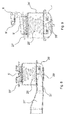
Fig. 3 is a sectional front view of a dishwasher equipped with a second embodiment of the regeneration-type drying device according to the invention; -
Fig. 4 shows in detail the drying device ofFig. 3 , without the dishwasher; -
Figs. 5 and6 are, respectively, a side view and a front view of the device ofFig. 4 ; -
Fig. 7 is a top view, with a sectioned part, of a detail of the device ofFigs. 4 to 6 ; -
Fig. 8 is a longitudinal sectional view of the detail ofFig. 7 ; -
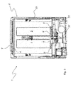
Fig. 9 is a sectional view of the same detail from an angle different from that ofFig. 8 . -
Fig. 10 is a sectional side view of a dishwasher equipped with the second embodiment of the regeneration-type drying device according to the invention. - With reference to the drawings, particularly to the first two figures,
numeral 1 designates as a whole a household appliance according to the invention, which in this case is a dishwasher. - The
dishwasher 1 is of a per se known type as concerns the typical functions used for washing and supporting the crockery S, but it includes adrying device 2 made in accordance with the invention. - Said device comprises a
collector 20 for recirculating the drying air, which extends from anair intake 4 arranged in an elevated position with respect to thewash tub 3 of the dishwasher, and anair outlet 5 on the bottom of the tub. - In this example, the collector is shown to be external to the household appliance for simplicity and clarity reasons, as will become more apparent below.
- It may however be provided inside the household appliance, in such a way as to be thermally insulated; to this end, the
collector 20 will be preferably insulated in a known manner, e.g. by wrapping it with an insulating material such as mineral wool, polymeric foam or the like. - In an intermediate region of the
collector 20 there is acontainer 24 for the hygroscopic material; in accordance with this embodiment, thecontainer 24 has a spherical shape, even though it may be different (e.g. cylindrical, parallelepiped or the like). - Inside the container there is an
electric resistor 25, which is controlled in a per se known manner through a regulator (not shown in the drawings). - In accordance with a preferred embodiment, the resistor is embedded into a layer of
silica gel 26. - This type of gel is available on the market, e.g. the one produced by German company Oker-Chemie GmbH; it has an adsorption capacity of approx. 25 % and a regeneration temperature around 180 °C.
- According to the invention, the
container 24 is also thermally insulated with mineral wool, polymeric foam or the like, so as to ensure good preservation of the heat generated therein by theresistor 25. - The
dishwasher 1 further comprises anintake fan 7 arranged at theintake 4, and adiffuser 8 associated with theoutlet 5; the former is used for circulating air inside thecollector 20 and thecontainer 24, down to the latter. Theoutlet 5 and thediffuser 8 protrude from the level corresponding to the maximum level of the water in the tub, and prevents the water on the tub bottom to flow back into thecollector 20. - The
protection device 8 essentially consists of a cover placed on top of the terminal part of theoutlet 5, which prevents any splashes of water from entering theoutlet 5. - The operation of the
dishwasher 1 can be easily understood in the light of the above description. - In order to dry the load in the
tub 3, in fact, the air present therein is circulated in thecollector 20 and in thecontainer 24, where its moisture content is adsorbed by thesilica gel layer 26 arranged in thecontainer 24. - At the beginning of an operating cycle of the machine, the silica gel is regenerated by the heat of the
resistor 25; however, since theregenerating device 2 can preserve heat well due to thecollector 20 and thecontainer 25 being thermally insulated, theelectric resistor 25 does not need to be powered continuously or for long time intervals. - It follows that the electric energy consumption at this stage of the operating cycle of the household appliance can be significantly lowered, thus meeting the energy efficiency classification requirements.
- This advantageous result is attained through a solution that does not require high costs for its industrial implementation, since de facto it only requires, the application of insulating material onto the
container 24 and, preferably but not necessarily, around thecollector 20. - In addition to its intrinsic low cost, this solution is advantageous because it can also be implemented in existing machines; in other words, the application of the insulating material requires no particular measures or modifications to existing household appliances having a regeneration system with a container or a collector for hygroscopic material; therefore, it is easily applicable at the industrial level.
- As possible variations of the invention described so far, reference should be made to the previous remarks regarding the arrangement of the
collector 20 and of thecontainer 24, which may be internal to the household appliance. - It can also be easily understood that, depending on this, also the shape of the collector, along with its
air intake 4 and theoutlet 5, as well as that of thecontainer 24 may be different from that shown. - As regards the hygroscopic material, it is apparent that many alternatives to silica gel may be used; in principle, any regenerable hygroscopic material may be used for the present invention.
- The above observations about the possible variations of the invention can be better understood with reference to
Figures 3 to 10 , which show a second embodiment of the drying device of the invention. - In such figures, an apostrophe has been added to the numerals of the various elements; those elements which are structurally or functionally equivalent to those already described have been designated by the same numerals.
- As can be seen, the dishwasher 1' comprises a drying device 2' in which a collector 20' extends along one side of the dishwasher from an upper region of the wash tub 3', where an air intake 4' with an impeller 7' is arranged, to a lower region, where there is an air outlet 5' for delivering the air into the tub 3'.
- In accordance with the variant of the invention shown in
Figures 3-10 , the drying device 2' also comprises asecond air intake 4" with itsimpeller 7" and asecond collector 20", which joins the first collector 20' upstream of the inlet of the container 24' for the hygroscopic material. The latter is similar to the one taken into account in the previous example, to which reference should be made for brevity. - It must however be pointed out that the
second collector 20" may be absent or there may be more than two collectors. - Unlike the previous example, in this case the hygroscopic material container 24' is arranged in the lower part of the dishwasher 1', under the bottom of the tub 3'.
- Preferably, at least one portion of the container 24' is in thermal exchange with the bottom of the tub 3' and/or with the liquid which is collected thereon during the operating cycle of the household appliance.
- The zeolite container 24' is connected to the collector 20' by means of a fitting 21', and is closed at the top by the outlet 5', from which a diffuser 8' extends whose function is to diffuse the drying air into the tub 3' while still preventing any wash water from entering it and flowing back into the container 24'.
- For this purpose, the diffuser is preferably split into two equal portions - even though there may be only one portion or more than two portions - each having a diverging configuration.
- Each portion 8' of the diffuser comprises apertures 9' for internal channels directed downwards, so that any splashes of wash liquid entering the diffuser 8' will fall outside without reaching the outlet 5' and the container 24'.
- The latter is cylindrical in shape and houses an electric resistor 25' which, in accordance with a preferred embodiment, has a helicoidal configuration; furthermore, as can be better observed in
Figures 8 and 9 , the helicoidal resistor 25' has a central part of smaller diameter than the ends. - These features of the resistor promote the thermal exchange with the hygroscopic material inside the container 24', into which the resistor 25' is buried, as well as with the air flowing into the regeneration-
type drying device 2. - The upper part of the container 24' and the diffuser 8' extend from the bottom of the tub 3' above the level that can be reached by the water during the operating cycle of the dishwasher 1'.
- This avoids any risk of flooding of the container while the household appliance 1' is in operation.
- Furthermore, the fact that the upper part of the container 24' with the outlet 5' protrudes from the bottom of the tub 3' still makes the thermal exchange with the water in the tub possible; advantageously, the exchange area can be increased by the presence of a collar or flange 27' surrounding the upper part of the container 24', which also acts as a thermal finning for the latter. In its lower part, the container 24' comprises a bottom 28', which is so shaped as to impart a rotary motion component to the air flow that goes through the regeneration-
type drying device 2. - For this purpose, the bottom 28' has a central convexity or relief 29' that defines, together with the rounded wall of the bottom 28', a toroidal chamber 30' with which a fluid inlet channel 31' is tangentially associated. The fluid, therefore, enters the toroidal chamber 28' with a tangential velocity component, goes through it, and flows upwards through the container 24' with helicoidal motion.
- This ensures that the distance run - and the time taken - by the fluid to flow through the container 24' is longer than in the case of a vertically ascending flow.
- This enhances the thermal exchange between the fluid and the hygroscopic material present in the container 24', all other conditions being equal, thereby improving the performance of the regeneration-type drying device according to the invention.
- Increased performance is also attained in regard to air diffusion in the washing tub 3'.
- In fact, thanks to the cantilever-style positioning of the diffuser 8' with respect to the bottom of the tub, the air taken in by the drying device 2' is delivered into the tub evenly and can therefore reach all internal points thereof.
- In this context, it must be pointed out that the cantilever-style positioning with respect to the bottom of the tub 3' facilitates the use of a double or multiple diffuser 8', since the portions that compose it can be oriented in respective different directions in order to improve the distribution of the air in the tub.
- It must also be pointed out that, due to the flange 27' and the outlet 5' being in thermal exchange with the water present on the bottom of the tub 3', it is possible to exploit the heat produced by the electric resistor 25' to regenerate the zeolites, thus advantageously saving energy.
- In fact, in accordance with the preferred operating cycle of the
household appliance 1, regeneration of the zeolites occurs during a step like the initial one, wherein wash water is supplied into the tub 3': it follows that the heat produced by the resistor 25' for heating the zeolites is also partly transmitted to the water present on the bottom of the tub 3', so that heating the latter will require less energy than in prior-art machines. - All features of the invention, in all of its possible variations, will still fall within the scope of the following claims.
Claims (14)
- A household appliance comprising a tub (3; 3') adapted to contain a load (S) to be treated, a regeneration-type drying device (2; 2'), in which an air flow laps the load (S) in the tub (3; 3') in order to dry it and then yields moisture to a hygroscopic material (26; 26'), means (25; 25') for heating the hygroscopic material (26; 26') in order to obtain the regeneration thereof, characterized in that the drying device (2; 2') supplies an air flow into the tub (3; 3') at a height above the bottom of the tub (3; 3').
- A household appliance according to claim 1, wherein the drying device (2; 2') comprises at least one element (5', 24', 27') in thermal exchange with a liquid present in the tub (3; 3').
- A household appliance according to claim 1 or 2, wherein the drying device (2; 2') comprises an outlet (5; 5') and/or a diffuser (8; 8') arranged in a cantilever fashion with respect to the bottom of the tub (3; 3') and extending up to a level higher than the preset one that is reached by the liquid collected on the bottom of the tub.
- A household appliance according to claim 3, wherein the diffuser is of the double or multiple type.
- A device according to any one of the preceding claims, wherein the means (25; 25') for heating the hygroscopic material (26; 26') comprise a helicoidal electric resistor with a central portion having a smaller diameter than the ends.
- A household appliance according to any one of the preceding claims, wherein the hygroscopic material (26; 26') is housed in a container (24; 24'), and wherein said air flow goes through said container with a helicoidal motion.
- A household appliance according to any one of the preceding claims, wherein the hygroscopic material (26; 26') is housed in a container (25; 25') which is at least partly thermally insulated by means of an insulation covering.
- A household appliance according to any one of the preceding claims, wherein the drying device (2) comprises a first collector (20') extending between a respective intake (4') for taking air from outside the tub (3; 3') and an outlet (5') for delivering the air into the tub (3; 3'), and a second collector (20") equipped with a respective intake (4"), which joins the first collector (20') upstream of the inlet of the hygroscopic material container (24').
- A household appliance according to any one of the preceding claims, wherein the first and/or the second collectors (20; 20', 20") are thermally insulated.
- A household appliance according to any one of the preceding claims, wherein the hygroscopic material comprises silica gel in granular form.
- A household appliance according to any one of the preceding claims, which is a dishwasher, a clothes dryer or a washing/drying machine.
- A method of operation of a household appliance comprising a tub (3; 3') adapted to contain a load (S) to be treated, a regeneration-type drying device (2; 2'), in which an air flow laps the load (S) in the tub (3; 3') in order to dry it and then yields moisture to a hygroscopic material (26; 26'), means (25; 25') for heating the hygroscopic material (26; 26') in order to obtain the regeneration thereof, characterized in that it comprises a step of regenerating the hygroscopic material, which is carried out during at least a part of the step of supplying water into the tub (3; 3').
- A method according to claim 12, wherein the step of regenerating the hygroscopic material (26; 26') comprises taking an air flow lapping the hygroscopic material (26; 26') from the tub (3; 3') and then delivering it again into the tub (3; 3').
- A method according to claims 12 or 13, wherein the air flow is delivered into the tub (3; 3') at a height above a preset level that is reached by the liquid collected on the bottom of the tub (3; 3').
Applications Claiming Priority (1)
| Application Number | Priority Date | Filing Date | Title |
|---|---|---|---|
| IT000597A ITTO20120597A1 (en) | 2012-07-06 | 2012-07-06 | APPLIANCES WITH REGENERATION DRYING DEVICE |
Publications (1)
| Publication Number | Publication Date |
|---|---|
| EP2682042A1 true EP2682042A1 (en) | 2014-01-08 |
Family
ID=46845921
Family Applications (1)
| Application Number | Title | Priority Date | Filing Date |
|---|---|---|---|
| EP13175289.1A Withdrawn EP2682042A1 (en) | 2012-07-06 | 2013-07-05 | Household appliance with regeneration drying device |
Country Status (2)
| Country | Link |
|---|---|
| EP (1) | EP2682042A1 (en) |
| IT (1) | ITTO20120597A1 (en) |
Citations (7)
| Publication number | Priority date | Publication date | Assignee | Title |
|---|---|---|---|---|
| EP0358279A1 (en) | 1988-09-09 | 1990-03-14 | Bauknecht Hausgeräte GmbH | Dish-drying device in a domestic dish-washing machine |
| DE10356787A1 (en) * | 2003-12-04 | 2005-07-07 | BSH Bosch und Siemens Hausgeräte GmbH | dishwasher |
| EP1667569A1 (en) | 2003-07-30 | 2006-06-14 | BSH Bosch und Siemens Hausgeräte GmbH | Dishwasher |
| EP1961362A2 (en) * | 2007-02-22 | 2008-08-27 | Premark FEG L.L.C. | Commercial dishwasher and method for its operation |
| DE102008056412A1 (en) * | 2008-11-07 | 2010-05-12 | BSH Bosch und Siemens Hausgeräte GmbH | Domestic appliance with an air-drying device and / or liquid heating device and associated method |
| EP2353486A2 (en) * | 2010-01-28 | 2011-08-10 | BSH Bosch und Siemens Hausgeräte GmbH | Dryer module for a dishwasher |
| EP2397064A1 (en) | 2010-06-17 | 2011-12-21 | Indesit Company S.p.A. | Method and device for drying for a drying or washing/drying machine |
Family Cites Families (4)
| Publication number | Priority date | Publication date | Assignee | Title |
|---|---|---|---|---|
| DE102005004096A1 (en) * | 2004-12-09 | 2006-06-14 | BSH Bosch und Siemens Hausgeräte GmbH | Dishwasher with a Sorptionstrockenvorrichtung |
| FR2879431B1 (en) * | 2004-12-21 | 2008-12-05 | Brandt Ind Sas | DISHWASHER AND METHOD OF IMPLEMENTING DRYING OF DISHWASHER IN THIS DISHWASHER |
| EP2389853A1 (en) * | 2010-05-24 | 2011-11-30 | Electrolux Home Products Corporation N.V. | Sorption drying device for a dishwasher and associated method |
| PL2389854T3 (en) * | 2010-05-24 | 2017-02-28 | Electrolux Home Products Corporation N.V. | Device and method for a dishwasher |
-
2012
- 2012-07-06 IT IT000597A patent/ITTO20120597A1/en unknown
-
2013
- 2013-07-05 EP EP13175289.1A patent/EP2682042A1/en not_active Withdrawn
Patent Citations (7)
| Publication number | Priority date | Publication date | Assignee | Title |
|---|---|---|---|---|
| EP0358279A1 (en) | 1988-09-09 | 1990-03-14 | Bauknecht Hausgeräte GmbH | Dish-drying device in a domestic dish-washing machine |
| EP1667569A1 (en) | 2003-07-30 | 2006-06-14 | BSH Bosch und Siemens Hausgeräte GmbH | Dishwasher |
| DE10356787A1 (en) * | 2003-12-04 | 2005-07-07 | BSH Bosch und Siemens Hausgeräte GmbH | dishwasher |
| EP1961362A2 (en) * | 2007-02-22 | 2008-08-27 | Premark FEG L.L.C. | Commercial dishwasher and method for its operation |
| DE102008056412A1 (en) * | 2008-11-07 | 2010-05-12 | BSH Bosch und Siemens Hausgeräte GmbH | Domestic appliance with an air-drying device and / or liquid heating device and associated method |
| EP2353486A2 (en) * | 2010-01-28 | 2011-08-10 | BSH Bosch und Siemens Hausgeräte GmbH | Dryer module for a dishwasher |
| EP2397064A1 (en) | 2010-06-17 | 2011-12-21 | Indesit Company S.p.A. | Method and device for drying for a drying or washing/drying machine |
Also Published As
| Publication number | Publication date |
|---|---|
| ITTO20120597A1 (en) | 2014-01-07 |
Similar Documents
| Publication | Publication Date | Title |
|---|---|---|
| US8961705B2 (en) | Dishwasher machine comprising a sorption drying system | |
| EP2246470B1 (en) | Washer-drier machine | |
| KR101792513B1 (en) | Heating cycle drying module of dishwasher using Fan module and PTC Heater | |
| CN105431070B (en) | Method for operating a dishwasher and dishwasher | |
| US8834645B2 (en) | Dishwasher having a sorption drying device | |
| KR20070085896A (en) | Dishwasher with sorption drying device and method of operation thereof | |
| KR20100113730A (en) | Dish washer | |
| EP2842475B1 (en) | Dish washer | |
| EP3082555B1 (en) | Dishwasher comprising heat pump system | |
| US20170164813A1 (en) | Dishwasher comprising a sorption drying machine | |
| KR102367064B1 (en) | Dishwasher | |
| EP2412861A1 (en) | Laundry washing and drying machine | |
| US9034115B2 (en) | Dishwasher machine comprising a sorption drying device | |
| AU2009286898B2 (en) | Dishwasher comprising a sorption drying unit | |
| US8709171B2 (en) | Dishwasher machine comprising a sorption drying device | |
| US20110126866A1 (en) | Dishwasher machine comprising a sorption drying device provided with a sorption material adapted in terms of weight to the wetting quantity in the washing compartment | |
| KR20140048493A (en) | Dish washer | |
| WO2016164515A1 (en) | Commercial dishwasher configured in the form of a box-type dishwasher and method of operating such a dishwasher | |
| KR20090124148A (en) | dish washer | |
| WO2012084488A2 (en) | A dishwasher comprising a dehumidifying unit | |
| CN209932643U (en) | Dish washing machine | |
| WO2012062680A1 (en) | A dishwasher with reduced energy consumption | |
| US20160192821A1 (en) | Dishwasher appliance having energy recovery features | |
| ITTO20120597A1 (en) | APPLIANCES WITH REGENERATION DRYING DEVICE |
Legal Events
| Date | Code | Title | Description |
|---|---|---|---|
| PUAI | Public reference made under article 153(3) epc to a published international application that has entered the european phase |
Free format text: ORIGINAL CODE: 0009012 |
|
| AK | Designated contracting states |
Kind code of ref document: A1 Designated state(s): AL AT BE BG CH CY CZ DE DK EE ES FI FR GB GR HR HU IE IS IT LI LT LU LV MC MK MT NL NO PL PT RO RS SE SI SK SM TR |
|
| AX | Request for extension of the european patent |
Extension state: BA ME |
|
| 17P | Request for examination filed |
Effective date: 20140828 |
|
| RBV | Designated contracting states (corrected) |
Designated state(s): AL AT BE BG CH CY CZ DE DK EE ES FI FR GB GR HR HU IE IS IT LI LT LU LV MC MK MT NL NO PL PT RO RS SE SI SK SM TR |
|
| RAP1 | Party data changed (applicant data changed or rights of an application transferred) |
Owner name: WHIRLPOOL EMEA S.P.A |
|
| STAA | Information on the status of an ep patent application or granted ep patent |
Free format text: STATUS: THE APPLICATION IS DEEMED TO BE WITHDRAWN |
|
| 18D | Application deemed to be withdrawn |
Effective date: 20180201 |