EP2397064A1 - Method and device for drying for a drying or washing/drying machine - Google Patents
Method and device for drying for a drying or washing/drying machine Download PDFInfo
- Publication number
- EP2397064A1 EP2397064A1 EP11170071A EP11170071A EP2397064A1 EP 2397064 A1 EP2397064 A1 EP 2397064A1 EP 11170071 A EP11170071 A EP 11170071A EP 11170071 A EP11170071 A EP 11170071A EP 2397064 A1 EP2397064 A1 EP 2397064A1
- Authority
- EP
- European Patent Office
- Prior art keywords
- drying
- hygroscopic material
- container
- machine
- air
- Prior art date
- Legal status (The legal status is an assumption and is not a legal conclusion. Google has not performed a legal analysis and makes no representation as to the accuracy of the status listed.)
- Withdrawn
Links
Images


Classifications
-
- A—HUMAN NECESSITIES
- A47—FURNITURE; DOMESTIC ARTICLES OR APPLIANCES; COFFEE MILLS; SPICE MILLS; SUCTION CLEANERS IN GENERAL
- A47L—DOMESTIC WASHING OR CLEANING; SUCTION CLEANERS IN GENERAL
- A47L15/00—Washing or rinsing machines for crockery or tableware
- A47L15/42—Details
- A47L15/48—Drying arrangements
- A47L15/481—Drying arrangements by using water absorbent materials, e.g. Zeolith
-
- D—TEXTILES; PAPER
- D06—TREATMENT OF TEXTILES OR THE LIKE; LAUNDERING; FLEXIBLE MATERIALS NOT OTHERWISE PROVIDED FOR
- D06F—LAUNDERING, DRYING, IRONING, PRESSING OR FOLDING TEXTILE ARTICLES
- D06F58/00—Domestic laundry dryers
- D06F58/20—General details of domestic laundry dryers
- D06F58/24—Condensing arrangements
Definitions
- the present invention relates to a method for drying objects in a drying or washing/drying machine, as well as to a device implementing said method.
- drying or washing/drying machine generally refers, in the present description and in the appended claims, lither to dishwashing machines having a drying function, as well as to clothes dryers and washing/drying machines.
- patent EP358279 teaches to dry crockery by having it lapped by a volume of dry air.
- the air volume is dried by having it lap a regenerable hygroscopic material, which absorbs the humidity of the air.
- This patent teaches how to regenerate (i.e. to dry) the hygroscopic material by subjecting it to a temperature increase caused by electric resistors heating it up, so that it yields the absorbed humidity and is then ready for a new cycle.
- regeneration refers to the release of humidity from the hygroscopic material, so that the latter can become dry again.
- the object of the present invention is to provide a method and a device for drying objects in a drying or washing/drying machine which can overcome these and other drawbacks.
- the present invention relates to a method for drying objects in a drying or washing/drying machine and a device implementing said method.
- the idea underlying of the present invention is to regenerate the hygroscopic material by subjecting it to a pressure which is lower than the atmospheric pressure, i.e. a pressure lower than 1 bar.
- the energy consumption of a pump or a compressor used for reducing the pressure is significantly lower than that of an electric resistor.
- the method and the device described hereafter can be used or implemented, in general, in any type of machine equipped with a drying function, whether for treating laundry (such as washing/drying machines, clothes dryers and the like) or for treating crockery (such as dishwashers).
- a drying function whether for treating laundry (such as washing/drying machines, clothes dryers and the like) or for treating crockery (such as dishwashers).
- FIG. 1 there is shown a basic configuration of a dishwasher adapted to implement the method of the present invention.
- the method comprises the two known basic steps of:
- steps b.,c.,d. may optionally be repeated for a preferred number of times.
- the basic method referred to above operates as a closed loop, wherein the air circulating within the machine is always the same and draws humidity from the crockery to yield it by contact to the regenerable hygroscopic material.
- the latter is dried at the beginning of the cycle, by lowering the pressure in the environment where it is housed, so as to reduce the vapour tension of the water absorbed by the regenerable hygroscopic material.
- a more complex embodiment of the method comprises the following steps:
- the above method includes two distinct phases, i.e. one to be carried out in open-loop mode and one to be carried out in closed-loop mode.
- the crockery is dried by simply subjecting it to a flow of environmental air, which is then exhausted out of the machine after the humidity has been lowered by means of a condenser or the like.
- the second closed-loop phase is substantially similar to the one described above, and is used to speed up the drying of the crockery, while at the same time providing a substantial energy saving.
- an air heating step may be provided by using suitable electric resistors.
- FIG. 1 illustrates the tub 2 of the dishwasher 1 that houses the crockery S.
- the exploded view shows a part of the circuit that can be used for implementing the method according to the present invention.
- circuit is an integral part of the machine 1, since it is housed therewithin; the exploded view in the annexed drawings is however useful to understand its operation and to identify its functional parts.
- first valve 4 preferably a solenoid valve, which is adapted to intercept the duct 3 itself.
- a container for a regenerable hygroscopic material 6 said container 6 being preferably hermetic except for an intake aperture and an exhaust aperture respectively connected to said air intake duct 3 and to an air exhaust duct 7, along which there is a vacuum pump 8 having preferably a power of approx. 100 W and a flow rate of 15 1t/min and being adapted to reach absolute pressures of approx. 0.12 bars.
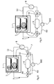
- Fig. 2 the machine 1 is carrying out the step a. for regenerating the hygroscopic material.
- valve 4 In this operating condition, the valve 4 is closed, i.e. it shuts off the air intake duct 3.
- the pump 8 is in operation so that the container 6, arranged between the valve 4 and the pump 8 itself, is placed by the latter into a vacuum condition at the above-mentioned pressure values. Therefore, the hygroscopic material contained in the container 6, through the effect of this pressure reduction, is dried and releases its humidity in the form of steam, which is then sent, through the air exhaust duct 7, and the pump 8 and the air supply duct 12, into the tub 2 or directly into the drain of the dishwasher 1 (not shown).
- valve 4 is opened, as shown in Fig. 3 .
- the pump 8 conveys a flow of dry air through the air supply duct, which air flows through the tub 2 and laps the crockery, thus subtracting humidity therefrom.
- the air which is now humid, then flows through the air intake duct and reaches the container 6, where it yields its humidity to the hygroscopic material contained therein.
- the circulating air flow is dry again, and reaches the pump 8 through the air exhaust duct 7, from where it is recirculated.
- FIGs. 2 and 3 show the path followed by the air flow (humid or dry, according to the case) by means of a dashed arrow.
- the crockery S is considered to be dry and the cycle stops.
- step a is carried out again in order to appropriately dry or regenerate the hygroscopic material.
- Fig. 4 shows an improved machine 10, wherein the same reference numerals designate the same parts of the machine 1, which will not be described any further.
- the machine 10 comprises a first three-way valve 40, a second three-way valve 50, and a bypass duct 60.
- the first valve 40 is located on the air intake duct 3 upstream of the container 6; the second valve 50 is located on the air exhaust duct 7 downstream of the container 6; the bypass duct 60 is connected to the first valve 40 and to the second valve 50.
- the first valve is therefore connected to: the air intake duct 3, the container 6 and the bypass duct 60; in its turn, the second valve 50 is connected to: the air exhaust duct 7, the container 6, and the bypass duct 60.
- the first valve 40 is actuated to close the air intake duct 3 and to place the container 6 in communication with the bypass duct 60; the second valve 50 is actuated to close the container 6 and to place the bypass duct 60 in fluidic communication with the air exhaust duct 7 directed towards the pump 8.
- the hygroscopic material contained in the latter is subjected to a pressure which is lower than the atmospheric pressure, and hence it yields humidity which is conveyed into the tub 2, as previously explained.
- the hygroscopic material which benefits the most from the pressure reduction, thus drying sooner and optimally, is immediately adjacent to the take-off point on the container 6.
- the dry air flow generated by the pump 8 is conveyed into the tub 2 and subtracts humidity from the crockery S.
- the latter is actuated in a manner such as to place the duct 3 in communication with the container 6 and to stop the fluidic communication with the bypass duct 60.
- the humid air flow then goes through the container 6, thus yielding humidity to the hygroscopic material and becoming dry again.
- valve 50 is actuated in a manner such as to place the container 6 in communication with the duct 7 and hence with the pump 8.
- the dry air flow exiting the container is thus delivered to the pump 8, and from there into the tub 2 again, so that the cycle can be repeated for a preferred number of times or until the crockery can be considered to be dry.
- the air take-off point during the hygroscopic material regeneration step coincides with the humid air supply point during the crockery drying step, it is advantageously attained that the portion of hygroscopic material that dries or regenerates best is that very portion which gets imbibed the most in the operating condition, since it is the first to come in contact with the humid air flow coming from the tub 2.
- FIG. 7 , 8 and 9 Yet another variation is shown in Figs. 7 , 8 and 9 .
- the machine 100 in this case, comprises a pump 900 arranged in line on the bypass duct 60, and a blower 800 arranged on the duct 7 that leads to the tub.
- the operation is similar to that previously described, the only difference being that the hygroscopic material drying step, shown in Fig. 8 , is carried out by turning on the pump 900 on the bypass duct 60 and leaving the blower 800 off, whereas the crockery drying step is carried out by turning off the pump 900 and turning on the blower 800, which leads to a further saving in terms of energy consumption, since the blower 800 absorbs less electric energy than the pump 900.
- the circuit that comprises the container 6 is housed in the base 20 of the machine (which is also adapted to house one or more pumps), thus saving room and improving the stability of the machine.
Abstract
Having an air volume lap a regenerable hygroscopic material, so as to lower the degree of humidity of the former;
having said air volume lap said crockery, and the step of
regenerating said regenerable hygroscopic material by subjecting it to a pressure which is lower than the atmospheric pressure.
The present invention also relates to a drying or washing/drying machine implementing said method.
Description
- The present invention relates to a method for drying objects in a drying or washing/drying machine, as well as to a device implementing said method.
- The term drying or washing/drying machine generally refers, in the present description and in the appended claims, lither to dishwashing machines having a drying function, as well as to clothes dryers and washing/drying machines.
- Referring to dishwashers, some models are currently available which also perform a crockery drying step that follows the washing of the crockery.
- For example, patent
EP358279 - The air volume is dried by having it lap a regenerable hygroscopic material, which absorbs the humidity of the air.
- This patent teaches how to regenerate (i.e. to dry) the hygroscopic material by subjecting it to a temperature increase caused by electric resistors heating it up, so that it yields the absorbed humidity and is then ready for a new cycle.
- Once the material has yielded the absorbed humidity, in fact, it is ready for being used in a new crockery drying cycle.
- This solution however requires much energy, due to the necessity of keeping the electric resistor on through the entire hygroscopic material regeneration time.
- The term "regeneration" as used herein refers to the release of humidity from the hygroscopic material, so that the latter can become dry again.
- The object of the present invention is to provide a method and a device for drying objects in a drying or washing/drying machine which can overcome these and other drawbacks.
- The present invention relates to a method for drying objects in a drying or washing/drying machine and a device implementing said method.
- The idea underlying of the present invention is to regenerate the hygroscopic material by subjecting it to a pressure which is lower than the atmospheric pressure, i.e. a pressure lower than 1 bar.
- The reduction of the pressure in the container of the regenerable hygroscopic material, in fact, allows the latter to release the humidity it contains without requiring the use of any electric heating resistors, resulting in an improvement over prior-art solutions.
- Advantageously, in fact, the energy consumption of a pump or a compressor used for reducing the pressure is significantly lower than that of an electric resistor.
- Let us consider, for example, that an electric resistor used for this application typically draws 1KW/h or more, whereas a pump ensuring the attainment of the same result typically draws 100 W/h, i.e. there is a difference of approximately one order of magnitude.
- It is another object of the present invention to provide a method for regenerating a hygroscopic material to be used in a drying or washing/drying machine, which method comprises the step of subjecting said hygroscopic material to a pressure which is lower than the atmospheric pressure.
- Further advantageous features will be set out in the appended claims, which are intended as an integral part of the present text.
- These features as well as further advantages of the present invention will become more apparent from the following description of an embodiment thereof, shown in the annexed drawings provided by way of non-limiting example, wherein:
-
Fig. 1 shows a diagram of a dishwasher according to a basic embodiment of the present invention; -
Figs. 2 and 3 show the dishwasher ofFig. 1 in two distinct operating conditions, i.e. a condition in which the hygroscopic material is being regenerated, and a condition in which the crockery is being dried; -
Fig. 4 shows a diagram of a dishwasher according to a first improved embodiment of the present invention; -
Figs. 5 and 6 show the dishwasher ofFig. 4 in two distinct operating conditions, i.e. a condition in which the hygroscopic material is being regenerated, and a condition in which the crockery is being dried; -
Fig. 7 shows a diagram of a dishwasher according to a second improved embodiment of the present invention; -
Figs. 8 and 9 show the dishwasher ofFig. 7 in two distinct operating conditions, i.e. a condition in which the hygroscopic material is being regenerated, and a condition in which the crockery is being dried. - In principle, the method and the device described hereafter can be used or implemented, in general, in any type of machine equipped with a drying function, whether for treating laundry (such as washing/drying machines, clothes dryers and the like) or for treating crockery (such as dishwashers).
- For simplicity, however, the following will describe an example of application in a dishwasher equipped with a crockery drying function.
- Any applications of the teachings of the present invention for laundry treating purposes should nonetheless be considered to fall within the scope of the present invention, in that all the necessary adaptations required by the differences between the two types of machines fall within the scope of the person skilled in the art.
- Referring now to
Fig. 1 , there is shown a basic configuration of a dishwasher adapted to implement the method of the present invention. - The method comprises the two known basic steps of:
-
s 1. having an air volume to lap a regenerable hygroscopic material, so as to lower the degree of humidity of the former; - s2. having said air volume to lap crockery to be dried;
- and, in accordance with the present invention, it further comprises the step of:
- a. regenerating said regenerable hygroscopic material by subjecting it to a pressure which is lower than the atmospheric pressure, preferably between 0.2 and 0.05 absolute bars.
In particular, this latter step of the method is applicable whenever one wants to regenerate a hygroscopic material, such as zeolites, before, during or after a crockery drying cycle in a dishwashing machine. A hygroscopic material which is particularly suitable for the implementation of the present method is a zeolite known to those skilled in the art under the commercial name SAPO-34.
The method according to the present invention lends itself to many applications, but it always comprises the above-mentioned step a.
Step a. may advantageously be carried out prior to the basic steps s1. and s2., leading to advantages that will be described more in detail below. Steps s1.,s2. may optionally be repeated for a preferred number of times.
Step a. may advantageously be carried out in the course of a crockery washing step being executed by said dishwasher, so that the cycle is not made longer by the execution of step a., and it is possible to use, in order to speed up the regeneration of the hygroscopic material, the heat possibly dispersed by the dishwasher during the washing step (it must be remembered that the dishwashers' washing steps typically utilize water at high temperature, i.e. at approx. 55°C).
This method step a. causes the regeneration of the regenerable hygroscopic material, which yields water that is collected into and expelled from the container, thus making the regenerable hygroscopic material ready for use.
At the end of a crockery wash cycle, the crockery temperature is relatively high (because of the high temperature of the wash liquid), and the humidity present in the tub of the washing machine and on the crockery itself (which is hot at the end of the wash cycle) tends to condense onto the tub walls, whose temperature is lower.
This determines a decrease in the humidity percentage, until a condition is reached wherein the "natural" drying process described so far is made difficult by the small temperature difference (less than 5°C) between the humid air in the tub and the tub walls, onto which the humidity should condense.
Once this condition has been attained, therefore, the "natural" drying of the crockery will continue, but will require a very long time to complete.
In order to improve this process, it is necessary to subtract the residual humidity from the dishes, so that at the end of this drying step they can be picked up substantially dry by the user. Advantageously, according to the method of the present invention the air to be conveyed against the crockery to enhance the drying thereof is dried by having it lap the hygroscopic material before being delivered into the tub.
To this end, it is necessary that the hygroscopic material be ready to dry the air, and therefore it must be dried, or regenerated, before it comes in contact with the air to be delivered onto the crockery.
In order to dry or regenerate the hygroscopic material, the above step a. is carried out.
As aforementioned, the energy consumption of a machine implementing this method is rather low, and is anyway lower than when the hygroscopic material is only regenerated through heating by means of electric resistors.
The drying method also comprises, in a basic embodiment of the present invention, the steps of: - b. generating an air flow;
- c. having said air flow to lap the crockery;
- d. having said air flow to lap said hygroscopic material.
- a. regenerating said regenerable hygroscopic material by subjecting it to a pressure which is lower than the atmospheric pressure, preferably between 0.2 and 0.05 absolute bars.
- The above steps b.,c.,d. may optionally be repeated for a preferred number of times.
- The basic method referred to above operates as a closed loop, wherein the air circulating within the machine is always the same and draws humidity from the crockery to yield it by contact to the regenerable hygroscopic material.
- The latter is dried at the beginning of the cycle, by lowering the pressure in the environment where it is housed, so as to reduce the vapour tension of the water absorbed by the regenerable hygroscopic material.
- A more complex embodiment of the method, for example, comprises the following steps:
- i. generating a first air flow taken from the environment outside the dishwasher;
- ii. having said first air flow to lap the wet crockery;
- iii. exhausting said first air flow into the environment outside the dishwasher;
- iv. (optional) repeating steps i,ii,iii for a preferred number oftimes;
- a. subjecting a regenerable hygroscopic material, housed in a container, to a pressure between 0.2 and 0.05 absolute bars;
- b. generating an air flow;
- c. having said air flow to lap the crockery;
- d. having said air flow to lap said hygroscopic material;
- e. (optional) repeating steps b,c,d for a preferred number of times.
- As can be seen, the above method includes two distinct phases, i.e. one to be carried out in open-loop mode and one to be carried out in closed-loop mode.
- During the first open-loop phase, the crockery is dried by simply subjecting it to a flow of environmental air, which is then exhausted out of the machine after the humidity has been lowered by means of a condenser or the like.
- The second closed-loop phase is substantially similar to the one described above, and is used to speed up the drying of the crockery, while at the same time providing a substantial energy saving.
- In this regard, it must be pointed out that when the crockery's humidity percentage is high, it can be subtracted relatively easily from the crockery but as it falls below a certain value, the water evaporation process becomes slower and the air coming from the environment may not be suitable because it is too humid.
- In this case as well, an air heating step may be provided by using suitable electric resistors.
- As for the
machine 1 capable of carrying out such a cycle, one example of a basic machine is shown inFig. 1 , which illustrates thetub 2 of thedishwasher 1 that houses the crockery S. The exploded view shows a part of the circuit that can be used for implementing the method according to the present invention. - Of course, in its practical implementation the circuit is an integral part of the
machine 1, since it is housed therewithin; the exploded view in the annexed drawings is however useful to understand its operation and to identify its functional parts. - In particular, with reference to
Fig. 1 , it can be seen that there is anair intake duct 3 in fluidic communication with thetub 2, which duct extends from the latter towards a container for a regenerablehygroscopic material 6. - Along the
air intake duct 3 there is afirst valve 4, preferably a solenoid valve, which is adapted to intercept theduct 3 itself. - There is also a container for a regenerable
hygroscopic material 6, saidcontainer 6 being preferably hermetic except for an intake aperture and an exhaust aperture respectively connected to saidair intake duct 3 and to anair exhaust duct 7, along which there is avacuum pump 8 having preferably a power of approx. 100 W and a flow rate of 15 1t/min and being adapted to reach absolute pressures of approx. 0.12 bars. - Downstream of the
pump 8 anair supply duct 12 is visible, which is in fluidic communication with thetub 2. - The operation of the system for carrying out the method of the present invention is shown in
Figs. 2 and 3 . - In
Fig. 2 themachine 1 is carrying out the step a. for regenerating the hygroscopic material. - In this operating condition, the
valve 4 is closed, i.e. it shuts off theair intake duct 3. - The
pump 8 is in operation so that thecontainer 6, arranged between thevalve 4 and thepump 8 itself, is placed by the latter into a vacuum condition at the above-mentioned pressure values. Therefore, the hygroscopic material contained in thecontainer 6, through the effect of this pressure reduction, is dried and releases its humidity in the form of steam, which is then sent, through theair exhaust duct 7, and thepump 8 and theair supply duct 12, into thetub 2 or directly into the drain of the dishwasher 1 (not shown). - After a predetermined time of operation in this condition, the
valve 4 is opened, as shown inFig. 3 . - In this situation, the
pump 8 conveys a flow of dry air through the air supply duct, which air flows through thetub 2 and laps the crockery, thus subtracting humidity therefrom. - The air, which is now humid, then flows through the air intake duct and reaches the
container 6, where it yields its humidity to the hygroscopic material contained therein. - At the outlet of the
container 6, the circulating air flow is dry again, and reaches thepump 8 through theair exhaust duct 7, from where it is recirculated. - For better readability,
Figs. 2 and 3 show the path followed by the air flow (humid or dry, according to the case) by means of a dashed arrow. - At the end of a preset time or, as an alternative, after a preferred number of cycles or upon reaching a preset humidity threshold, controllable through suitable sensors, the crockery S is considered to be dry and the cycle stops.
- During the next drying cycle, the above-described step a. is carried out again in order to appropriately dry or regenerate the hygroscopic material.
- Of course, the method described so far and the machine implementing it may be subject to many variations.
- One of these variations is shown in
Fig. 4 ,5 and 6 . -
Fig. 4 shows animproved machine 10, wherein the same reference numerals designate the same parts of themachine 1, which will not be described any further. - The
machine 10 comprises a first three-way valve 40, a second three-way valve 50, and abypass duct 60. - The
first valve 40 is located on theair intake duct 3 upstream of thecontainer 6; thesecond valve 50 is located on theair exhaust duct 7 downstream of thecontainer 6; thebypass duct 60 is connected to thefirst valve 40 and to thesecond valve 50. - The first valve is therefore connected to: the
air intake duct 3, thecontainer 6 and thebypass duct 60; in its turn, thesecond valve 50 is connected to: theair exhaust duct 7, thecontainer 6, and thebypass duct 60. - The process taking place during the step of regenerating the hygroscopic material contained in the
container 6 is shown inFig. 5 . - The
first valve 40 is actuated to close theair intake duct 3 and to place thecontainer 6 in communication with thebypass duct 60; thesecond valve 50 is actuated to close thecontainer 6 and to place thebypass duct 60 in fluidic communication with theair exhaust duct 7 directed towards thepump 8. - The latter is then turned on, resulting in the
container 6 being placed under a vacuum. - Because of the duct layout and of the fact that the bypass duct is connected to the head of the
container 6, the hygroscopic material contained in the latter is subjected to a pressure which is lower than the atmospheric pressure, and hence it yields humidity which is conveyed into thetub 2, as previously explained. - The hygroscopic material which benefits the most from the pressure reduction, thus drying sooner and optimally, is immediately adjacent to the take-off point on the
container 6. - During the operating step in which the crockery S is dried, as shown in
Fig. 6 , the dry air flow generated by thepump 8 is conveyed into thetub 2 and subtracts humidity from the crockery S. - The air flow, now humid, exits the tub through the
duct 3 and then reaches thevalve 40. - The latter is actuated in a manner such as to place the
duct 3 in communication with thecontainer 6 and to stop the fluidic communication with thebypass duct 60. - The humid air flow then goes through the
container 6, thus yielding humidity to the hygroscopic material and becoming dry again. - At the outlet of the container, the
valve 50 is actuated in a manner such as to place thecontainer 6 in communication with theduct 7 and hence with thepump 8. - The dry air flow exiting the container is thus delivered to the
pump 8, and from there into thetub 2 again, so that the cycle can be repeated for a preferred number of times or until the crockery can be considered to be dry. - Since with this configuration the air take-off point during the hygroscopic material regeneration step coincides with the humid air supply point during the crockery drying step, it is advantageously attained that the portion of hygroscopic material that dries or regenerates best is that very portion which gets imbibed the most in the operating condition, since it is the first to come in contact with the humid air flow coming from the
tub 2. - Yet another variation is shown in
Figs. 7 ,8 and 9 . - In these drawings, the same reference numerals designate the same parts previously described and having the same functions, which will not therefore be described any further.
- The
machine 100, in this case, comprises apump 900 arranged in line on thebypass duct 60, and ablower 800 arranged on theduct 7 that leads to the tub. - The operation is similar to that previously described, the only difference being that the hygroscopic material drying step, shown in
Fig. 8 , is carried out by turning on thepump 900 on thebypass duct 60 and leaving theblower 800 off, whereas the crockery drying step is carried out by turning off thepump 900 and turning on theblower 800, which leads to a further saving in terms of energy consumption, since theblower 800 absorbs less electric energy than thepump 900. - Other changes may of course be made to the method as well as to the machine implementing it; for example, the closed loop shown in the drawings and described so far may alternatively be replaced with an open loop, or comprise ducts afferent to the outside environment. Advantageously, then, the circuit that comprises the
container 6 is housed in thebase 20 of the machine (which is also adapted to house one or more pumps), thus saving room and improving the stability of the machine.
Claims (10)
- A method for drying objects, such as crockery, in a drying or washing/drying machine, comprising the steps of:s 1. having an air volume to lap a regenerable hygroscopic material, so as to lower the degree of humidity of the former;s2. having said air volume to lap said objects;characterized in thatit further comprises the step of:a. regenerating said regenerable hygroscopic material by subjecting it to a pressure which is lower than the atmospheric pressure.
- A method according to claim 1, characterized in that said pressure lower than the atmospheric pressure is between 0.2 and 0.05 absolute bars.
- A method according to claim 1 or 2, characterized by further comprising the following steps:b. generating an air flow;c. having said air flow to lap the objects;d. having said air flow to lap said hygroscopic material;to be preferably carried out after said step a.
- A method according to one or more of the preceding claims, characterized in that said step a. is carried out during a wash cycle.
- A drying or washing/drying machine (1,10,100), in particular a dishwasher with a crockery drying function, characterized in that it implements the method according to one or more of claims 1 to 4.
- A machine (1,10,100) according to claim 5, characterized in that it comprises a tub (2) adapted to house objects (S), such as crockery, to be subjected to a drying action, and a container (6) adapted to house a regenerable hygroscopic material, said container (6) being in fluidic communication with said tub (2) and with a pump (8,800) in order to be subjected to a pressure which is lower than the atmospheric pressure.
- A machine (1,10) according to claim 6, characterized by comprising:- an air intake duct (3) in fluidic communication with said tub (2) and with said container (6),- a valve (4,40) adapted to intercept said air intake duct (3),- a vacuum pump (8),- an air exhaust duct (7) connected to said container (6) and to a vacuum pump (8),- an air supply duct (12) in fluidic communication with said pump (8) and with said tub (2).
- A machine (10) according to claim 7, characterized by further comprising:- a bypass duct (60),- a second three-way valve (50) connected to the air exhaust duct (7), to the container (6) and to said bypass duct 60,
wherein said first valve (40) is a three-way valve connected to said air intake duct (3), to said container (6) and to said bypass duct (60). - A machine (1,10) according to one or more of claims 5 to 8, characterized in that at least said container (6) is housed in a base (20) of the machine (1,10,100) which also houses one or more pumps.
- A method for regenerating a regenerable hygroscopic material which can be implemented in a drying or washing/drying machine, in particular in a dishwasher, comprising the step of:a. regenerating said regenerable hygroscopic material by subjecting it to a pressure which is lower than the atmospheric pressure.
Applications Claiming Priority (1)
| Application Number | Priority Date | Filing Date | Title |
|---|---|---|---|
| ITTO2010A000526A IT1400548B1 (en) | 2010-06-17 | 2010-06-17 | METHOD AND DEVICE FOR DRYING IN A DRYING MACHINE OR WASHING MACHINE |
Publications (1)
| Publication Number | Publication Date |
|---|---|
| EP2397064A1 true EP2397064A1 (en) | 2011-12-21 |
Family
ID=43740409
Family Applications (1)
| Application Number | Title | Priority Date | Filing Date |
|---|---|---|---|
| EP11170071A Withdrawn EP2397064A1 (en) | 2010-06-17 | 2011-06-15 | Method and device for drying for a drying or washing/drying machine |
Country Status (2)
| Country | Link |
|---|---|
| EP (1) | EP2397064A1 (en) |
| IT (1) | IT1400548B1 (en) |
Cited By (2)
| Publication number | Priority date | Publication date | Assignee | Title |
|---|---|---|---|---|
| EP2682042A1 (en) | 2012-07-06 | 2014-01-08 | Indesit Company S.p.A. | Household appliance with regeneration drying device |
| DE102010047058B4 (en) * | 2009-10-06 | 2015-11-26 | Sanhua Aweco Appliance Systems Gmbh | Household machine with a drying of wet objects |
Citations (5)
| Publication number | Priority date | Publication date | Assignee | Title |
|---|---|---|---|---|
| EP0358279A1 (en) | 1988-09-09 | 1990-03-14 | Bauknecht Hausgeräte GmbH | Dish-drying device in a domestic dish-washing machine |
| EP0777998A1 (en) * | 1995-12-09 | 1997-06-11 | Whirlpool Europe B.V. | Method of saving energy in domestic appliances and appliance with improved energy efficiency |
| WO2002003002A1 (en) * | 2000-07-05 | 2002-01-10 | Smart Clean | Combination closed-circuit washer and drier |
| DE102007033494A1 (en) * | 2007-07-18 | 2009-01-22 | BSH Bosch und Siemens Hausgeräte GmbH | adsorption |
| DE102007052083A1 (en) * | 2007-10-31 | 2009-05-07 | BSH Bosch und Siemens Hausgeräte GmbH | Domestic appliance with adsorption dryer |
-
2010
- 2010-06-17 IT ITTO2010A000526A patent/IT1400548B1/en active
-
2011
- 2011-06-15 EP EP11170071A patent/EP2397064A1/en not_active Withdrawn
Patent Citations (5)
| Publication number | Priority date | Publication date | Assignee | Title |
|---|---|---|---|---|
| EP0358279A1 (en) | 1988-09-09 | 1990-03-14 | Bauknecht Hausgeräte GmbH | Dish-drying device in a domestic dish-washing machine |
| EP0777998A1 (en) * | 1995-12-09 | 1997-06-11 | Whirlpool Europe B.V. | Method of saving energy in domestic appliances and appliance with improved energy efficiency |
| WO2002003002A1 (en) * | 2000-07-05 | 2002-01-10 | Smart Clean | Combination closed-circuit washer and drier |
| DE102007033494A1 (en) * | 2007-07-18 | 2009-01-22 | BSH Bosch und Siemens Hausgeräte GmbH | adsorption |
| DE102007052083A1 (en) * | 2007-10-31 | 2009-05-07 | BSH Bosch und Siemens Hausgeräte GmbH | Domestic appliance with adsorption dryer |
Cited By (2)
| Publication number | Priority date | Publication date | Assignee | Title |
|---|---|---|---|---|
| DE102010047058B4 (en) * | 2009-10-06 | 2015-11-26 | Sanhua Aweco Appliance Systems Gmbh | Household machine with a drying of wet objects |
| EP2682042A1 (en) | 2012-07-06 | 2014-01-08 | Indesit Company S.p.A. | Household appliance with regeneration drying device |
Also Published As
| Publication number | Publication date |
|---|---|
| ITTO20100526A1 (en) | 2011-12-18 |
| IT1400548B1 (en) | 2013-06-11 |
Similar Documents
| Publication | Publication Date | Title |
|---|---|---|
| EP2014820B1 (en) | Method of determining clogging of the steam generator tank filter of a home laundry drier, and home laundry drier implementing such a method | |
| JP4778522B2 (en) | Dishwasher | |
| US20110048464A1 (en) | Dishwasher and associated control method | |
| JP2008522685A5 (en) | ||
| ATE501664T1 (en) | DISHWASHER | |
| US8137440B2 (en) | Dryer having structure for enhanced drying and method of use | |
| EP3102084B1 (en) | A dishwasher, a door assembly for the dishwasher, and an associated method for drying dishware | |
| EP2634301B1 (en) | Household laundry washing and drying machine with a condensing device and method of operating this machine | |
| CN111041765A (en) | Washing and drying integrated machine and control method thereof | |
| US20100043833A1 (en) | Controlling method of dishwasher | |
| EP2163682B1 (en) | Home laundry drier | |
| CN106149329A (en) | Dryer condensation water collection vaporising device, dryer and control method thereof | |
| CN109549586B (en) | Dish washing machine drying method, dish washing machine control method and dish washing machine | |
| KR20130087847A (en) | Dish washer with dehumidifying device | |
| CN101187137A (en) | Washes processing machine condensed water discharging device | |
| EP2397064A1 (en) | Method and device for drying for a drying or washing/drying machine | |
| JP7121186B2 (en) | Condensed water recycling system and dryer | |
| WO2015063016A1 (en) | A laundry dryer with increased ventilating effectiveness | |
| EP3214991B1 (en) | Household appliance comprising desiccant material | |
| CN102655800B (en) | For alleviating the dish-washing machine of the band ion generator of cacogeusia | |
| WO2013050468A1 (en) | A dishwasher comprising a dehumidifying unit | |
| WO2013097975A1 (en) | A washer comprising a dehumidifying unit | |
| EP3138953A1 (en) | A laundry dryer comprising a filter | |
| CN205188631U (en) | Washing machine with mould proof function of disinfecting | |
| EP3875018A1 (en) | Air ducting system with adsorber, household appliance with an air ducting system and method of operating a household appliance |
Legal Events
| Date | Code | Title | Description |
|---|---|---|---|
| AK | Designated contracting states |
Kind code of ref document: A1 Designated state(s): AL AT BE BG CH CY CZ DE DK EE ES FI FR GB GR HR HU IE IS IT LI LT LU LV MC MK MT NL NO PL PT RO RS SE SI SK SM TR |
|
| AX | Request for extension of the european patent |
Extension state: BA ME |
|
| PUAI | Public reference made under article 153(3) epc to a published international application that has entered the european phase |
Free format text: ORIGINAL CODE: 0009012 |
|
| 17P | Request for examination filed |
Effective date: 20120621 |
|
| RAP1 | Party data changed (applicant data changed or rights of an application transferred) |
Owner name: WHIRLPOOL EMEA S.P.A |
|
| 17Q | First examination report despatched |
Effective date: 20171027 |
|
| STAA | Information on the status of an ep patent application or granted ep patent |
Free format text: STATUS: THE APPLICATION IS DEEMED TO BE WITHDRAWN |
|
| 18D | Application deemed to be withdrawn |
Effective date: 20190926 |