EP2681796B1 - Solid polymer electrolyte type fuel cell, and electrolyte membrane-electrode-frame assembly - Google Patents
Solid polymer electrolyte type fuel cell, and electrolyte membrane-electrode-frame assembly Download PDFInfo
- Publication number
- EP2681796B1 EP2681796B1 EP13718654.0A EP13718654A EP2681796B1 EP 2681796 B1 EP2681796 B1 EP 2681796B1 EP 13718654 A EP13718654 A EP 13718654A EP 2681796 B1 EP2681796 B1 EP 2681796B1
- Authority
- EP
- European Patent Office
- Prior art keywords
- frame
- electrolyte membrane
- peripheral portion
- inner peripheral
- electrode
- Prior art date
- Legal status (The legal status is an assumption and is not a legal conclusion. Google has not performed a legal analysis and makes no representation as to the accuracy of the status listed.)
- Active
Links
Images


Classifications
-
- H—ELECTRICITY
- H01—ELECTRIC ELEMENTS
- H01M—PROCESSES OR MEANS, e.g. BATTERIES, FOR THE DIRECT CONVERSION OF CHEMICAL ENERGY INTO ELECTRICAL ENERGY
- H01M8/00—Fuel cells; Manufacture thereof
- H01M8/002—Shape, form of a fuel cell
- H01M8/006—Flat
-
- H—ELECTRICITY
- H01—ELECTRIC ELEMENTS
- H01M—PROCESSES OR MEANS, e.g. BATTERIES, FOR THE DIRECT CONVERSION OF CHEMICAL ENERGY INTO ELECTRICAL ENERGY
- H01M8/00—Fuel cells; Manufacture thereof
- H01M8/02—Details
- H01M8/0202—Collectors; Separators, e.g. bipolar separators; Interconnectors
- H01M8/0258—Collectors; Separators, e.g. bipolar separators; Interconnectors characterised by the configuration of channels, e.g. by the flow field of the reactant or coolant
- H01M8/0263—Collectors; Separators, e.g. bipolar separators; Interconnectors characterised by the configuration of channels, e.g. by the flow field of the reactant or coolant having meandering or serpentine paths
-
- H—ELECTRICITY
- H01—ELECTRIC ELEMENTS
- H01M—PROCESSES OR MEANS, e.g. BATTERIES, FOR THE DIRECT CONVERSION OF CHEMICAL ENERGY INTO ELECTRICAL ENERGY
- H01M8/00—Fuel cells; Manufacture thereof
- H01M8/02—Details
- H01M8/0202—Collectors; Separators, e.g. bipolar separators; Interconnectors
- H01M8/0267—Collectors; Separators, e.g. bipolar separators; Interconnectors having heating or cooling means, e.g. heaters or coolant flow channels
-
- H—ELECTRICITY
- H01—ELECTRIC ELEMENTS
- H01M—PROCESSES OR MEANS, e.g. BATTERIES, FOR THE DIRECT CONVERSION OF CHEMICAL ENERGY INTO ELECTRICAL ENERGY
- H01M8/00—Fuel cells; Manufacture thereof
- H01M8/02—Details
- H01M8/0271—Sealing or supporting means around electrodes, matrices or membranes
- H01M8/0273—Sealing or supporting means around electrodes, matrices or membranes with sealing or supporting means in the form of a frame
-
- H—ELECTRICITY
- H01—ELECTRIC ELEMENTS
- H01M—PROCESSES OR MEANS, e.g. BATTERIES, FOR THE DIRECT CONVERSION OF CHEMICAL ENERGY INTO ELECTRICAL ENERGY
- H01M8/00—Fuel cells; Manufacture thereof
- H01M8/24—Grouping of fuel cells, e.g. stacking of fuel cells
- H01M8/241—Grouping of fuel cells, e.g. stacking of fuel cells with solid or matrix-supported electrolytes
- H01M8/242—Grouping of fuel cells, e.g. stacking of fuel cells with solid or matrix-supported electrolytes comprising framed electrodes or intermediary frame-like gaskets
-
- H—ELECTRICITY
- H01—ELECTRIC ELEMENTS
- H01M—PROCESSES OR MEANS, e.g. BATTERIES, FOR THE DIRECT CONVERSION OF CHEMICAL ENERGY INTO ELECTRICAL ENERGY
- H01M8/00—Fuel cells; Manufacture thereof
- H01M8/24—Grouping of fuel cells, e.g. stacking of fuel cells
- H01M8/2465—Details of groupings of fuel cells
- H01M8/2483—Details of groupings of fuel cells characterised by internal manifolds
-
- H—ELECTRICITY
- H01—ELECTRIC ELEMENTS
- H01M—PROCESSES OR MEANS, e.g. BATTERIES, FOR THE DIRECT CONVERSION OF CHEMICAL ENERGY INTO ELECTRICAL ENERGY
- H01M8/00—Fuel cells; Manufacture thereof
- H01M8/10—Fuel cells with solid electrolytes
- H01M2008/1095—Fuel cells with polymeric electrolytes
-
- Y—GENERAL TAGGING OF NEW TECHNOLOGICAL DEVELOPMENTS; GENERAL TAGGING OF CROSS-SECTIONAL TECHNOLOGIES SPANNING OVER SEVERAL SECTIONS OF THE IPC; TECHNICAL SUBJECTS COVERED BY FORMER USPC CROSS-REFERENCE ART COLLECTIONS [XRACs] AND DIGESTS
- Y02—TECHNOLOGIES OR APPLICATIONS FOR MITIGATION OR ADAPTATION AGAINST CLIMATE CHANGE
- Y02E—REDUCTION OF GREENHOUSE GAS [GHG] EMISSIONS, RELATED TO ENERGY GENERATION, TRANSMISSION OR DISTRIBUTION
- Y02E60/00—Enabling technologies; Technologies with a potential or indirect contribution to GHG emissions mitigation
- Y02E60/30—Hydrogen technology
- Y02E60/50—Fuel cells
Definitions
- the present invention relates to a solid polymer electrolyte type fuel cell, and an electrolyte membrane-electrode-frame assembly of the fuel cell.
- the solid polymer electrolyte type fuel cell includes a polymer electrolyte membrane that is capable of selectively transporting hydrogen ions, and a pair of electrodes (including an anode and a cathode) that are formed on both surfaces of the electrolyte membrane.
- Each of the electrodes includes a catalyst layer formed on a surface of the electrolyte membrane, and a gas diffusion layer (GDL) that is disposed on an outer side of the catalyst layer and has both gas permeability and electron conductivity.
- GDL gas diffusion layer
- MEA electrolyte membrane-electrode assembly
- the MEA is interposed and mechanically fixed between a pair of conductive separators, and adjacent MEAs are electrically connected to each other in series.
- a gas flow channel is formed at a portion, which comes into contact with the MEA, of each of the separators.
- a reaction gas is supplied to each of the electrodes through the gas flow channel to remove generated water or a redundant gas from the electrode.
- a structure body in which the MEA is interposed between the pair of separators is referred to as a single cell module (cell).
- a penetration hole which is called a manifold hole, is formed at an edge portion of each of the separators so as to supply the reaction gas to the gas flow channel of the separator.
- the reaction gas that flows through the penetration hole is distributed to the gas flow channels of a plurality of the separators.
- a sealing member is disposed between the pair of separators to surround the outer periphery of an electrode forming portion (that is, a power generation region) of the MEA so as to prevent the reaction gas supplied to the gas flow channels or the like from being leaked to the outside or being mixed.
- FIG. 11 illustrates a manufacturing process of MEA 101 disclosed in PTL 1.
- MEA 101 and reinforcing frame 102 are disposed separately from each other in mold 105, and rubber 103 is filled in a separation portion.
- Rubber 103 is impregnated in gas diffusion layer (GDL) 104 that constitutes MEA 101, whereby MEA 101 and reinforcing frame 102 are integrated each other.
- GDL gas diffusion layer
- FIG. 12 shows a diagram illustrating electrolyte membrane catalyst laminated body 201 of the related art disclosed in PTL 2.
- electrolyte membrane catalyst laminated body 201 includes electrolyte membrane 203 in which catalyst layer 202 is disposed on both surfaces thereof, and reinforcing sheet 204 including adhesive layer 205 and elastic layer 206, the adhesive layer 205 being bonded to an outer circumferential surface of electrolyte membrane 203.
- the MEA of the solid polymer electrolyte type fuel cell it is required for the MEA of the solid polymer electrolyte type fuel cell to have high durability.
- a pressure is applied to the electrolyte membrane or the gas diffusion layer for filling rubber 103, and in the result there is a possibility that the electrolyte membrane or the gas diffusion layer may be mechanically fractured.
- electrode membrane-catalyst layer laminated body 201 ( FIG. 12 ) of PTL 2
- a gap is present between the catalyst layer laminated on both surfaces of the electrolyte membrane and the reinforcing sheet, and in result the electrolyte membrane or the catalyst layer is directly exposed to a gas fluid. Therefore, deterioration of the electrolyte membrane is accelerated, and there is a problem with durability.
- the invention has been made to solve the problems in the related art, and an object thereof is to provide a solid polymer electrolyte type fuel cell having an MEA with high durability.
- a solid polymer electrolyte type fuel cell comprising stacked single cell modules, each including an electrolyte membrane-electrode-frame assembly, a pair of separators that interpose the electrolyte membrane-electrode-frame assembly therebetween from the anode side and the cathode side, and a pair of gas diffusion layers.
- the electrolyte membrane-electrode-frame assembly includes: a catalyst layer-attached electrolyte membrane having a polymer electrolyte membrane, an anode catalyst provided on one surface of the polymer electrolyte membrane, and a cathode catalyst provided on the other surface of the polymer electrolyte membrane; and a frame that is disposed at a peripheral portion of the catalyst layer-attached electrolyte membrane, includes a gas supply portion configured to supply a fuel gas and an oxidant gas to the anode catalyst and the cathode catalyst, respectively, and has a rectangular inner periphery.
- the pair of gas diffusion layers is disposed between the pair of separators and the electrolyte membrane-electrode-frame assembly and are laminated to cover an inner peripheral portion of the frame.
- a thickness of at least a part of a corner portion of the inner peripheral portion of the frame is smaller than a thickness of a linear side portion of the inner peripheral portion of the frame.
- a gap is not likely to occur between the frame and the gas diffusion layer. Accordingly, it is possible to provide a solid polymer electrolyte type fuel cell having an MEA with high durability while the electrolyte membrane or the catalyst layer is not directly exposed to a gas.
- an overload which occurs when the gas diffusion layers are twisted and overlap each other, does not occur. Accordingly, damage to the electrolyte membrane or the gas diffusion layers, which occurs due to the overload, is reduced.
- a fuel cell is, for example, a solid polymer electrolyte type fuel cell (PEFC), and generates electric power, heat, and water at the same time by allowing a hydrogencontaining fuel gas and an oxygen-containing oxidant gas such as air to electrochemically react with each other.
- PEFC solid polymer electrolyte type fuel cell
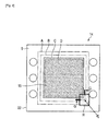
- FIG. 1 shows an exploded perspective diagram schematically illustrating a partial structure of fuel cell stack 1, that is, an example of the polymer electrolyte type fuel cell (PEFC).
- PEFC polymer electrolyte type fuel cell
- fuel cell stack 1 includes a plurality of single cell modules (cell) 2, and these modules are stacked in series.
- Fuel cell stack 1 includes a plurality of single cell modules (cells) 2, and a pair of current collector plates 3 and a pair of end plates 4 that are disposed at both ends. Fastening of fuel cell stack 1 is carried out using four fastening bolts 7 that penetrate through volt holes 6, respectively, and four nuts 8.
- Current collector plates 3 are disposed on both sides of a stack of single cell modules 2. Each current collector plate 3 is a member that efficiently collects electricity generated by the single cell modules.
- Current collector plate 3 is a copper plate that is plated with, for example, gold.
- current collector plate 3 may be a metallic plate with satisfactory electric conductivity, for example, a metallic plate of iron, stainless steel, aluminum, or the like.
- current collector plate 3 may be subjected to a surface treatment such as tin plating and nickel plating.
- Each end plate 4 using an electrically insulating material is disposed at an outer side of current collector plate 3.
- End plate 4 also functions as an insulating plate.
- the end plate 4 is manufactured by injection-molding a polyphenylene sulfide resin.
- Spring 5 is disposed at an inner side of end plate 4. Spring 5 applies a load to the stack of single cell modules 2. Spring 5 is disposed at the central region of end plate 4 so as to easily apply the load to a power generation region of MEA 10. The load due to spring 5 is adjusted by a fastening pressure of fastening volts 7 and nuts 8 during assembling of fuel cell stack 1.
- End plate 4 is integrally molded with a pair of pipes 30A, pipes 30C, and pipes 30W.
- Pipes 30A, pipes 30C, and pipes 30W communicate with manifold holes 12 (12A, 12C, and 12W) of single cell modules 2, respectively.
- Each single cell module 2 includes electrolyte membrane-electrode-frame assembly 14 having frame 9 at a peripheral portion of MEA 10, a pair of conductive separators (including anode side separator 11A and cathode side separator 11C) that interposes electrolyte membrane-electrode-frame assembly 14 therebetween, and cooling water separator 11 W.
- Bolt holes 6 and manifold holes 12 are formed in frame 9 and separators 11(11A, 11C, and 11W), respectively, frame 9 being disposed at the peripheral portion of MEA 10 constituting electrolyte membrane-electrode-frame assembly 14.
- Manifold holes 12 include a pair of penetration holes 12A through which a fuel gas flows, a pair of penetration holes 12C through which an oxidant gas flows, and a pair of penetration holes 12W through which cooling water flows.
- bolt holes 6 communicate with each other, and the manifold holes communicate with each other.
- Anode side separator 11A and cathode side separator 11C have a flat plate shape, and a surface (inner surface) thereof on a side that comes into contact with MEA 10 is shaped in conformity with a shape of MEA 10. Furthermore, fuel gas flow channel groove 13A is formed on the inner surface of the anode side separator 11A, and also an oxidant gas flow channel groove 13C is formed on the inner surface of the cathode side separator 11C. And further, cooling water flow channel groove 13W is formed on the surface of separator 11W.
- Each of separators 11 is formed from a gas non-permeable conductive material, and for example, a member obtained by cutting a resin-impregnated carbon material into a predetermined shape, a member that is obtained by molding a mixture of carbon powders and a resin material, or a member that is obtained by shaping a metal are generally used.
- manifold holes 12A communicate with each other to form a fuel gas manifold
- manifold holes 12C communicate with each other to form an oxidant gas manifold
- manifold holes 12W communicate with each other to form a cooling water manifold.
- a gasket is disposed between separators 11 (11A and 11C) and frame 9.
- the gasket is constituted by an elastic body. It is preferable that the gasket is formed integrally with each of separators 11.
- the gasket is pressed in fuel cell stack 1 so as to deform in correspondence with a shape of frame 9 of MEA 10, and as a result the gasket seals an outer periphery of MEA 10 or an outer periphery of manifold holes 12. According to this sealing, the fuel gas, the oxidant gas and the cooling water are prevented from being leaked from a gap between adjacent single cell modules 2, or a connection portion of respective manifold holes 12.
- FIGS. 2 to 4 show a configuration of electrolyte membrane-electrode-frame assembly 14 (refer to FIG. 1 ).
- FIG. 2B shows a top view of electrolyte membrane-electrode-frame assembly 14.
- FIG. 2A shows a partial cross-sectional diagram of MEA 10 of electrolyte membrane-electrode-frame assembly 14.
- MEA 10 includes polymer electrolyte membrane 15 that selectively transports hydrogen ions, catalyst layer (anode catalyst layer) 16 that is disposed on an anode surface side of polymer electrolyte membrane 15, and catalyst layer (cathode catalyst layer) 17 that is disposed on a cathode surface side of polymer electrolyte membrane 15.
- electrolyte membrane 15 a solid polymer material that exhibits proton conductivity, for example, perfluorosulfonic acid membrane (Nafion membrane manufactured by Du Pont Kabushiki Kaisha) can be generally used.
- Catalyst layer (anode catalyst) 16 may be a catalyst layer containing carbon powders on which a platinum-ruthenium alloy catalyst is supported, as a main component.
- Catalyst layer (cathode catalyst) 17 may be a catalyst layer containing carbon powders on which a platinum catalyst is supported, as a main component.
- gas diffusion layer (GDL) 18 is laminated in MEA 10, gas diffusion layer (GDL) 18 being disposed at outer sides of catalyst layer (anode catalyst) 16 and catalyst layer (cathode catalyst) 17, and having both fuel gas or oxidant gas permeability and electron conductivity.
- Gas diffusion layer (GDL) 18 may be or may not be integrated with electrolyte membrane 15, catalyst layer (anode catalyst) 16, and catalyst layer (cathode catalyst) 17.
- FIG. 3 shows a top view of electrolyte membrane-electrode-frame assembly 14.
- a region surrounded by “line A” is a region in which electrolyte membrane 15 and catalyst layers 16 and 17 are disposed.
- a region surrounded by “line B” is a region in which gas diffusion layer (GDL) 18 is disposed.
- GDL gas diffusion layer
- Line C represents an inner peripheral side of frame 9.
- a region surrounded by “line D” is a power generation region.
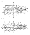
- FIGS. 4A and 4B show partial cross-sectional diagrams of single cell module 2 (refer to FIG. 1 ), which includes a cross-section taken along a line D-D of electrolyte membrane-electrode-frame assembly 14 in FIG. 2 .
- FIG. 4A shows a partial cross-sectional diagram illustrating an exploded state of single cell module 2.
- FIG. 4B shows a partial cross-sectional diagram illustrating a state of single cell module 2 assembled into fuel cell stack 1.
- electrolyte membrane-electrode-frame assembly 14 includes electrolyte membrane 15 in which catalyst layers 16 and 17 are laminated on both surfaces thereof, and a picture-frame-shaped frame 9 into which a peripheral portion of electrolyte membrane 15 is inserted.
- catalyst layers 16 and 17 are omitted.
- Frame 9 may be a resin molded product.
- frame 9 may be obtained by bonding two frame precursors with the peripheral portion of electrolyte membrane 15 interposed therebetween. The bonding of the two frame precursors is performed by disposing a bonding portion 19 on a bonding surface.
- the bonding portion 19 may be a resin molded product, or may be constituted by an adhesive or the like.
- a pair of gas diffusion layers (GDLs) 18 is disposed on both surfaces of the catalyst layer-attached electrolyte membrane-frame assembly, respectively.
- Each gas diffusion layers (GDLs) 18 is laminated on frame 9 so as to overlap the inner peripheral portion of frame 9. In this way, electrolyte membrane 15 is inserted in frame 9, and then gas diffusion layers (GDLs) 18 are joined.
- electrolyte membrane-electrode-frame assembly 14 may be manufactured without applying an excessive pressure to electrolyte membrane 15, and thus durability of MEA 10 of electrolyte membrane-electrode-frame assembly 14 may be increased.
- a thickness of a part (convex portion E) of the inner peripheral portion of frame 9, into which electrolyte membrane 15 is inserted is set to be larger than a thickness of the outer peripheral portion thereof.
- Gas diffusion layers (GDLs) 18 ride on convex portion E with a large thickness.
- gas diffusion layers (GDLs) 18 placed on the inner peripheral portion of frame 9 are configured to fill a space (gap) between separator 11 and frame 9.
- Electrolyte membrane 15 to which the catalyst layers are bonded may be prevented from being exposed. Electrolyte membrane 15, which is exposed, may come into direct contact with a gas, and thus may deteriorate. Electrolyte membrane 15 of the MEA according to Embodiment 1 is prevented from deteriorating, and thus durability thereof is improved.
- gas diffusion layers (GDLs) 18 are disposed to ride on the inner peripheral portion of frame 9, a gap between separator 11 and frame 9 on an outer side in relation to the power generation region (in FIG. 3 , the region surrounded by the line D) is filled with gas diffusion layer (GDL) 18 that is composed of elastic body. Accordingly, a gas is prevented from being leaked to the outside of the power generation region, and a cross leakage is suppressed in which the gas goes around from an anode electrode to a cathode electrode through an end surface of electrolyte membrane 15.
- FIG. 5 shows a cross-section, which is taken along a line G-G of electrolyte membrane-electrode-frame assembly 14 shown in FIG. 3 , in a case of assuming that the inner peripheral portion of frame 9 has the same height over the entire periphery.
- the case in which the inner peripheral portion of frame 9 has the same height over the entire periphery can mean that convex portion E is formed along the inner peripheral portion of frame 9 over the entire periphery.
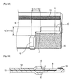
- FIG. 6 shows an exploded diagram of electrolyte membrane-electrode-frame assembly 14 of Embodiment 1.
- FIG. 6 illustrates configurations of corner portion X of the inner peripheral portion of frame 9 and a part of gas diffusion layers (GDLs) 18. Due to the configuration illustrated in FIG. 6 , even when the overlapping and twisting of gas diffusion layers (GDLs) 18 occur at corner portion X shown in FIG. 5 , an excessive load is not likely to be applied to the corner portion X. That is, electrolyte membrane 15 and gas diffusion layers (GDLs) 18 are not likely to be fractured. Hereinafter, a reason thereof will be described.
- FIG. 6 shows a schematic diagram in which a range of electrolyte membrane-electrode-frame assembly 14 surrounded by a line H in FIG. 3 is exploded and enlarged.
- the height of corner portion X of the inner peripheral portion of frame 9 is set to be the same as the height of the outer peripheral portion of frame 9. That is, the height of corner portion X of the inner peripheral portion of frame 9 is configured to be lower than the height of convex portion E along the linear side portion of the inner peripheral portion of frame 9.
- a dotted line of FIG. 6 indicates a region in which gas diffusion layers (GDLs) 18 are disposed.
- Gas diffusion layers (GDLs) 18 are disposed to ride on convex portion E along the linear side portion of the inner peripheral portion of frame 9.
- FIG. 7 shows a cross-sectional diagram along a line I-I of electrolyte membrane-electrode-frame assembly 14 in FIG. 6 .
- FIG. 8 shows a cross-section, which is taken along the line G-G (refer to FIG. 3 ), of the corner portion of the electrolyte membrane-electrode-frame assembly 14 of Embodiment 1.
- the height of corner portion X of the inner peripheral portion of frame 9 is the same as the height of the outer peripheral portion of frame 9. That is, the height of corner portion X of the inner peripheral portion of frame 9 is configured to be lower than the height of convex portion E along the linear side portion of the inner peripheral portion of frame 9. Accordingly, as shown in FIG. 8 , even when gas diffusion layers (GDLs) 18 overlap each other or are twisted at corner portion X of the inner peripheral portion of frame 9, the thickness of single cell module 2 does not increases, and may be set to a predetermined thickness.
- GDLs gas diffusion layers
- the thickness of corner portion X of the inner peripheral portion of frame 9 on which gas diffusion layers (GDLs) 18 ride is set to be smaller than the thickness of convex portion E of the linear side portion of the inner peripheral portion of frame 9, the thickness of single cell module 2 is set to be maintained in a predetermined thickness, even when gas diffusion layers (GDLs) 18 overlap each other or are twisted at corner portion X.
- a fastening load of fuel cell stack 1 may be appropriately maintained, and thus an excessive load is not applied to frame 9 or electrolyte membrane 15, and fracture of electrolyte membrane 15 and gas diffusion layers (GDLs) 18 is suppressed.
- durability of the single cell module may be increased.
- FIG. 9A shows a schematic diagram of frame 9 within a range surrounded by the line H of electrolyte membrane-electrode-frame assembly 14 in FIG. 3 .
- FIG. 9B shows a cross-sectional diagram taken along a line K-K in FIG. 9A .
- a corner portion of the inner peripheral portion of frame 9 is set in a square region surrounded by a dotted line J.
- the thickness of the convex portion along the linear portion of the inner peripheral portion of frame 9 is set to a "thickness j.” It is preferable that a length of one side of the square region surrounded by the dotted line J be 1 to 10 times the "thickness j.” In Embodiment 1, the length of the one side of the square region, which constitutes the corner portion and is surrounded by the dotted line J, is set to five times the "thickness j.” It is preferable that a gap space between separator 11 and frame 9 be small.
- an area of the square region which is the corner portion of the inner peripheral portion of frame 9 and is surrounded by the dotted line J, be set to be small within a range with which the thickness of single cell module 2 at the corner portion does not increase due to overlapping of gas diffusion layers (GDLs) 18.
- GDLs gas diffusion layers
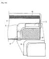
- FIG. 10A illustrates a configuration of corner portion X of an inner peripheral portion of frame 9 in electrolyte membrane-electrode-frame assembly 14 according to Embodiment 2.
- GDLs gas diffusion layers
- Both an inner peripheral edge of corner portion X of the inner peripheral portion of frame 9 in electrolyte membrane-electrode-frame assembly 14 shown in FIG. 10A , and an outer edge of the corner portion of gas diffusion layers (GDLs) 18 have an arc shape.
- the thickness of single cell modules 2 may be maintained to a predetermined thickness. Accordingly, a fastening load of fuel cell stack 1 may be appropriately maintained, and thus an excessive load is not applied to frame 9 or electrolyte membrane 15. As a result, durability of the single cell module may be increased.
- Embodiment 2 since the inner peripheral side of corner portion X of the inner peripheral portion of frame 9 has the arc shape, resin molding of frame 9 becomes easy.
- FIG. 10B illustrates a configuration of corner portion X of an inner peripheral portion of frame 9 in electrolyte membrane-electrode-frame assembly 14 according to Embodiment 3.
- Embodiment 3 overload due to overlapping of gas diffusion layers (GDLs) 18 or deterioration of MEA 10 is suppressed.
- GDLs gas diffusion layers
- Protrusion Y having the same height as the convex portion of the linear side portion of the inner peripheral portion of frame 9 is provided at a part of corner portion X of the inner peripheral portion of frame 9 in electrolyte membrane-electrode-frame assembly 14 shown in FIG. 10B .
- the thickness of single cell modules 2 may be maintained to a predetermined thickness. Accordingly, a fastening load of fuel cell stack 1 may be appropriately maintained, and thus an excessive load is not applied to frame 9 or electrolyte membrane 15. As a result, durability of the single cell module may be increased.
- protrusion Y is provided at a part of corner portion X of the inner peripheral portion of frame 9, there is an advantage in that alignment of gas diffusion layers (GDLs) 18 becomes easy.
- a polymer electrolyte membrane was obtained by punching, for example, a resin material (Nafion (registered trademark) N-117, manufactured by Du Pont Kabushiki Kaisha) having a thickness of 50 micro meter using a Thomson mold.
- a resin material Nafion (registered trademark) N-117, manufactured by Du Pont Kabushiki Kaisha
- An anode catalyst layer and a cathode catalyst layer were formed on both surfaces of the obtained polymer electrolyte membrane using an applying method, whereby a catalyst layer-attached electrolyte membrane was obtained.
- the anode catalyst layer and the cathode catalyst layer were formed at the central portion of the polymer electrolyte membrane instead of being formed on the entire surface thereof, and were not formed in the vicinity of an outer peripheral side.
- modified polyphenylene ether (modified PPE) was resin-molded to prepare two frame precursors. A peripheral portion of the catalyst-attached electrolyte membrane was interposed between the two frame precursors. As shown in FIG. 4 , the bonding portion 19 made of the modified PPE was resin-molded on the bonding surface, and the two frame precursors were bonded to each other. In this manner, a catalyst layer-attached electrolyte membrane-frame assembly was obtained.
- the thickness of the outer peripheral portion of the frame was set to 0.8 mm, and the height j (refer to FIG. 9B ) of convex portion E of the linear side portion of the inner peripheral portion of the frame was set to 0.5 mm.
- the width of convex portion E was set to 2.5 mm.
- One side of the range (region surrounded by the dotted line J) of corner portion X was set to 3.5 mm.
- the inner peripheral edge of the corner portion was set to an arc shape (refer to FIG. 10A ).
- the gas diffusion layers were bonded to both surfaces of the catalyst layer-attached electrolyte membrane-frame assembly on an anode side and a cathode side, respectively, whereby an electrolyte membrane-electrode-frame assembly was obtained.
- An area of the gas diffusion layer was set to be the same as an area of the catalyst layer that was formed using the application method. According to this, as indicated by the dotted line in FIG. 10A , the gas diffusion layer (GDL) was laminated to ride on convex portion E up to an outer peripheral edge of convex portion E.
- the gas diffusion layer (GDL) was constituted by a diffusion layer containing carbon as a main component and having porosity of approximately 50%.
- the electrolyte membrane-electrode-frame assembly that was prepared as described above was interposed between an anode side separator and a cathode side separator, whereby a single cell module was obtained.
- 50 single cell modules were stacked, and metallic current collector plate 3, and end plate 4 formed from an electrically insulating material and functioning also as an insulating plate were disposed at both end portions of the stacked single cell modules, respectively (refer to FIG. 1 ). Furthermore, these components were fixed with fastening bolt 7 and nut 8, whereby a polymer electrolyte type fuel cell was obtained.
- Pressure sensitive paper was disposed on an interface between electrolyte membrane-electrode-frame assembly 14 and separator 11 in an arbitrary single cell module contained in the polymer electrolyte type fuel cell.
- Two kinds of pressure sensitive paper in which a pressurized portion shows a red color was used, one is a paper for super ultra-low pressure (0.2 to 0.6 MPa) and the other is paper for ultra-low pressure (0.5 to 2.5 MPa)
- the solid polymer electrolyte type fuel cell related to the invention may be manufactured without applying a molding pressure to an electrolyte membrane and a gas diffusion layer (GDL). Accordingly, deterioration of the electrolyte membrane and the gas diffusion layer (GDL) is suppressed. Furthermore, according to the solid polymer electrolyte type fuel cell related to the invention, deterioration of the electrolyte membrane due to an excessive fastening load may be suppressed. Therefore, the invention may improve the performance of the polymer electrolyte type fuel cell.
- the solid polymer electrolyte type fuel cell related to the invention is useful as a fuel cell that is used in, for example, a portable power supply, a power supply for an electric vehicle, an in-house cogeneration system, and the like.
Description
- The present invention relates to a solid polymer electrolyte type fuel cell, and an electrolyte membrane-electrode-frame assembly of the fuel cell.
- The solid polymer electrolyte type fuel cell includes a polymer electrolyte membrane that is capable of selectively transporting hydrogen ions, and a pair of electrodes (including an anode and a cathode) that are formed on both surfaces of the electrolyte membrane. Each of the electrodes includes a catalyst layer formed on a surface of the electrolyte membrane, and a gas diffusion layer (GDL) that is disposed on an outer side of the catalyst layer and has both gas permeability and electron conductivity. In this manner, a member obtained by integrally joining and assembling the electrolyte membrane and the electrodes is referred to as an electrolyte membrane-electrode assembly (MEA).
- The MEA is interposed and mechanically fixed between a pair of conductive separators, and adjacent MEAs are electrically connected to each other in series. A gas flow channel is formed at a portion, which comes into contact with the MEA, of each of the separators. A reaction gas is supplied to each of the electrodes through the gas flow channel to remove generated water or a redundant gas from the electrode. In this manner, a structure body in which the MEA is interposed between the pair of separators is referred to as a single cell module (cell).
- A penetration hole, which is called a manifold hole, is formed at an edge portion of each of the separators so as to supply the reaction gas to the gas flow channel of the separator. The reaction gas that flows through the penetration hole is distributed to the gas flow channels of a plurality of the separators.
- Furthermore, a sealing member is disposed between the pair of separators to surround the outer periphery of an electrode forming portion (that is, a power generation region) of the MEA so as to prevent the reaction gas supplied to the gas flow channels or the like from being leaked to the outside or being mixed.
- As an electrolyte membrane-electrode assembly in the related art, an assembly in which a frame, a reinforcing sheet, a gasket, and the like are formed in the outer periphery of the MEA is known (For example, refer to
PTL 1 to PTL 8). For example,FIG. 11 illustrates a manufacturing process of MEA 101 disclosed inPTL 1. InFIG. 11 , MEA 101 and reinforcingframe 102 are disposed separately from each other inmold 105, andrubber 103 is filled in a separation portion.Rubber 103 is impregnated in gas diffusion layer (GDL) 104 that constitutes MEA 101, whereby MEA 101 and reinforcingframe 102 are integrated each other. - In addition,
FIG. 12 shows a diagram illustrating electrolyte membrane catalyst laminatedbody 201 of the related art disclosed inPTL 2. InFIG. 12 , electrolyte membrane catalyst laminatedbody 201 includeselectrolyte membrane 203 in whichcatalyst layer 202 is disposed on both surfaces thereof, and reinforcingsheet 204 includingadhesive layer 205 andelastic layer 206, theadhesive layer 205 being bonded to an outer circumferential surface ofelectrolyte membrane 203. - Furthermore, a method of suppressing damage of the gas diffusion layer and the electrolyte membrane in the solid polymer electrolyte type fuel cell is suggested (refer to
PTL 9 and PTL 10). -
- PTL 1: Japanese Patent Application Laid-Open No.
2008-177001 - PTL 2: Japanese Patent Application Laid-Open No.
2010-067602 - PTL 3: International Publication No.
2008/126350 - PTL 4:
US Patent Application Laid-Open No. 2010/0104913 - PTL 5: Japanese Translation of a PCT Application Laid-Open No.
2009-505364 - PTL 6:
US Patent Application Laid-Open No. 2010/0291462 - PTL 7: International Publication No.
02/001658 - PTL 8:
US Patent Application Laid-Open No. 2003/0104262 - PTL 9: Japanese Patent Application Laid-Open No.
2005-235736 - PTL 10:
US Patent Application Laid-Open No. 2005/0181263 - It is required for the MEA of the solid polymer electrolyte type fuel cell to have high durability. However, for example, in the manufacturing of the MEA (
FIG. 11 ) ofPTL 1, a pressure is applied to the electrolyte membrane or the gas diffusion layer for fillingrubber 103, and in the result there is a possibility that the electrolyte membrane or the gas diffusion layer may be mechanically fractured. - In addition, in electrode membrane-catalyst layer laminated body 201 (
FIG. 12 ) ofPTL 2, a gap is present between the catalyst layer laminated on both surfaces of the electrolyte membrane and the reinforcing sheet, and in result the electrolyte membrane or the catalyst layer is directly exposed to a gas fluid. Therefore, deterioration of the electrolyte membrane is accelerated, and there is a problem with durability. - The invention has been made to solve the problems in the related art, and an object thereof is to provide a solid polymer electrolyte type fuel cell having an MEA with high durability.
- According to the invention as defined in
claim 1, there is provided a solid polymer electrolyte type fuel cell comprising stacked single cell modules, each including an electrolyte membrane-electrode-frame assembly, a pair of separators that interpose the electrolyte membrane-electrode-frame assembly therebetween from the anode side and the cathode side, and a pair of gas diffusion layers. The electrolyte membrane-electrode-frame assembly includes: a catalyst layer-attached electrolyte membrane having a polymer electrolyte membrane, an anode catalyst provided on one surface of the polymer electrolyte membrane, and a cathode catalyst provided on the other surface of the polymer electrolyte membrane; and a frame that is disposed at a peripheral portion of the catalyst layer-attached electrolyte membrane, includes a gas supply portion configured to supply a fuel gas and an oxidant gas to the anode catalyst and the cathode catalyst, respectively, and has a rectangular inner periphery. The pair of gas diffusion layers is disposed between the pair of separators and the electrolyte membrane-electrode-frame assembly and are laminated to cover an inner peripheral portion of the frame. A thickness of at least a part of a corner portion of the inner peripheral portion of the frame is smaller than a thickness of a linear side portion of the inner peripheral portion of the frame. - According to the above-described configurations, a gap is not likely to occur between the frame and the gas diffusion layer. Accordingly, it is possible to provide a solid polymer electrolyte type fuel cell having an MEA with high durability while the electrolyte membrane or the catalyst layer is not directly exposed to a gas. In addition, in the polymer electrolyte type fuel cell comprising stacked single cell modules, an overload, which occurs when the gas diffusion layers are twisted and overlap each other, does not occur. Accordingly, damage to the electrolyte membrane or the gas diffusion layers, which occurs due to the overload, is reduced.
- As a result, it is possible to provide a high-durability MEA in which the damage to the electrolyte membrane and the gas diffusion layer is small.
-
-
FIG. 1 is an exploded perspective diagram of a fuel cell stack. -
FIG. 2 is a configuration diagram of an electrolyte membrane-electrode-frame assembly according toEmbodiment 1. -
FIG. 3 is a schematic diagram of the electrolyte membrane-electrode-frame assembly according toEmbodiment 1. -
FIG. 4A shows an exploded state of a single cell module according toEmbodiment 1, and is a partial cross-sectional diagram of the electrolyte membrane-electrode-frame assembly and a pair of separators. -
FIG. 4B illustrates a laminated state of a single cell module according toEmbodiment 1, and is a partial cross-sectional diagram of the electrolyte membrane-electrode-frame assembly and the pair of separators. -
FIG. 5 is a cross-sectional diagram of a corner portion of the electrolyte membrane-electrode-frame assembly in a case of assuming that an inner peripheral portion of the frame has the same height over the entire periphery. -
FIG. 6 illustrates an exploded state of the electrolyte membrane-electrode-frame assembly according toEmbodiment 1, and is a schematic diagram partially illustrating a corner portion of the inner peripheral portion of the frame and a gas diffusion layer (GDL). -
FIG. 7 illustrates an exploded state of the single cell module according toEmbodiment 1, and is a partial cross-sectional diagram of a corner portion of the electrolyte membrane-electrode-frame assembly and a separator. -
FIG. 8 is a cross-sectional diagram of the corner portion of the electrolyte membrane-electrode-frame assembly according toEmbodiment 1. -
FIG. 9A is a schematic diagram of a corner portion of the frame of the electrolyte membrane-electrode-frame assembly according toEmbodiment 1. -
FIG. 9B is a partial cross-sectional diagram of the electrolyte membrane-electrode-frame assembly according toEmbodiment 1. -
FIG. 10A is a schematic diagram partially illustrating an exploded state of an electrolyte membrane-electrode-frame assembly, and a corner portion of an inner peripheral portion of the frame and a gas diffusion layer (GDL) according toEmbodiment 2. -
FIG. 10B is a schematic diagram partially illustrating an exploded state of an electrolyte membrane-electrode-frame assembly, and a corner portion of an inner peripheral portion of the frame and a gas diffusion layer (GDL) according to Embodiment 3. -
FIG. 11 is a diagram illustrating an MEA in the related art. -
FIG. 12 is a diagram illustrating an MEA in the related art. - Hereinafter, embodiments of the invention will be described with reference to the attached drawings.
- A fuel cell is, for example, a solid polymer electrolyte type fuel cell (PEFC), and generates electric power, heat, and water at the same time by allowing a hydrogencontaining fuel gas and an oxygen-containing oxidant gas such as air to electrochemically react with each other.
-
FIG. 1 shows an exploded perspective diagram schematically illustrating a partial structure offuel cell stack 1, that is, an example of the polymer electrolyte type fuel cell (PEFC). - As shown in
FIG. 1 ,fuel cell stack 1 includes a plurality of single cell modules (cell) 2, and these modules are stacked in series.Fuel cell stack 1 includes a plurality of single cell modules (cells) 2, and a pair of current collector plates 3 and a pair of end plates 4 that are disposed at both ends. Fastening offuel cell stack 1 is carried out using four fastening bolts 7 that penetrate through volt holes 6, respectively, and four nuts 8. - Current collector plates 3 are disposed on both sides of a stack of
single cell modules 2. Each current collector plate 3 is a member that efficiently collects electricity generated by the single cell modules. Current collector plate 3 is a copper plate that is plated with, for example, gold. In addition, current collector plate 3 may be a metallic plate with satisfactory electric conductivity, for example, a metallic plate of iron, stainless steel, aluminum, or the like. In addition, current collector plate 3 may be subjected to a surface treatment such as tin plating and nickel plating. - Each end plate 4 using an electrically insulating material is disposed at an outer side of current collector plate 3. End plate 4 also functions as an insulating plate. For example, the end plate 4 is manufactured by injection-molding a polyphenylene sulfide resin.
-
Spring 5 is disposed at an inner side of end plate 4.Spring 5 applies a load to the stack ofsingle cell modules 2.Spring 5 is disposed at the central region of end plate 4 so as to easily apply the load to a power generation region ofMEA 10. The load due tospring 5 is adjusted by a fastening pressure of fastening volts 7 and nuts 8 during assembling offuel cell stack 1. - End plate 4 is integrally molded with a pair of
pipes 30A,pipes 30C, andpipes 30W.Pipes 30A,pipes 30C, andpipes 30W communicate with manifold holes 12 (12A, 12C, and 12W) ofsingle cell modules 2, respectively. - Each
single cell module 2 includes electrolyte membrane-electrode-frame assembly 14 havingframe 9 at a peripheral portion ofMEA 10, a pair of conductive separators (includinganode side separator 11A andcathode side separator 11C) that interposes electrolyte membrane-electrode-frame assembly 14 therebetween, and coolingwater separator 11 W. - Bolt holes 6 and manifold holes 12 (12A, 12C, and 12W) are formed in
frame 9 and separators 11(11A, 11C, and 11W), respectively,frame 9 being disposed at the peripheral portion ofMEA 10 constituting electrolyte membrane-electrode-frame assembly 14. Manifold holes 12 include a pair ofpenetration holes 12A through which a fuel gas flows, a pair ofpenetration holes 12C through which an oxidant gas flows, and a pair ofpenetration holes 12W through which cooling water flows. In the stack ofsingle cell modules 2, bolt holes 6 communicate with each other, and the manifold holes communicate with each other. -
Anode side separator 11A andcathode side separator 11C have a flat plate shape, and a surface (inner surface) thereof on a side that comes into contact withMEA 10 is shaped in conformity with a shape ofMEA 10. Furthermore, fuel gasflow channel groove 13A is formed on the inner surface of theanode side separator 11A, and also an oxidant gasflow channel groove 13C is formed on the inner surface of thecathode side separator 11C. And further, cooling waterflow channel groove 13W is formed on the surface ofseparator 11W. - Each of
separators 11 is formed from a gas non-permeable conductive material, and for example, a member obtained by cutting a resin-impregnated carbon material into a predetermined shape, a member that is obtained by molding a mixture of carbon powders and a resin material, or a member that is obtained by shaping a metal are generally used. - When the plurality of
single cell modules 2 are stacked,manifold holes 12A communicate with each other to form a fuel gas manifold,manifold holes 12C communicate with each other to form an oxidant gas manifold, andmanifold holes 12W communicate with each other to form a cooling water manifold. - Although not shown in
FIG. 1 , a gasket is disposed between separators 11 (11A and 11C) andframe 9. The gasket is constituted by an elastic body. It is preferable that the gasket is formed integrally with each ofseparators 11. The gasket is pressed infuel cell stack 1 so as to deform in correspondence with a shape offrame 9 ofMEA 10, and as a result the gasket seals an outer periphery ofMEA 10 or an outer periphery of manifold holes 12. According to this sealing, the fuel gas, the oxidant gas and the cooling water are prevented from being leaked from a gap between adjacentsingle cell modules 2, or a connection portion of respective manifold holes 12. -
FIGS. 2 to 4 show a configuration of electrolyte membrane-electrode-frame assembly 14 (refer toFIG. 1 ). -
FIG. 2B shows a top view of electrolyte membrane-electrode-frame assembly 14.FIG. 2A shows a partial cross-sectional diagram ofMEA 10 of electrolyte membrane-electrode-frame assembly 14. - As shown in the partial cross-sectional diagram of
FIG. 2A ,MEA 10 includespolymer electrolyte membrane 15 that selectively transports hydrogen ions, catalyst layer (anode catalyst layer) 16 that is disposed on an anode surface side ofpolymer electrolyte membrane 15, and catalyst layer (cathode catalyst layer) 17 that is disposed on a cathode surface side ofpolymer electrolyte membrane 15. - As
electrolyte membrane 15, a solid polymer material that exhibits proton conductivity, for example, perfluorosulfonic acid membrane (Nafion membrane manufactured by Du Pont Kabushiki Kaisha) can be generally used. Catalyst layer (anode catalyst) 16 may be a catalyst layer containing carbon powders on which a platinum-ruthenium alloy catalyst is supported, as a main component. Catalyst layer (cathode catalyst) 17 may be a catalyst layer containing carbon powders on which a platinum catalyst is supported, as a main component. - Furthermore, gas diffusion layer (GDL) 18 is laminated in
MEA 10, gas diffusion layer (GDL) 18 being disposed at outer sides of catalyst layer (anode catalyst) 16 and catalyst layer (cathode catalyst) 17, and having both fuel gas or oxidant gas permeability and electron conductivity. Gas diffusion layer (GDL) 18 may be or may not be integrated withelectrolyte membrane 15, catalyst layer (anode catalyst) 16, and catalyst layer (cathode catalyst) 17. -
FIG. 3 shows a top view of electrolyte membrane-electrode-frame assembly 14. A region surrounded by "line A" is a region in whichelectrolyte membrane 15 and catalyst layers 16 and 17 are disposed. A region surrounded by "line B" is a region in which gas diffusion layer (GDL) 18 is disposed. "Line C" represents an inner peripheral side offrame 9. A region surrounded by "line D" is a power generation region. -
FIGS. 4A and 4B show partial cross-sectional diagrams of single cell module 2 (refer toFIG. 1 ), which includes a cross-section taken along a line D-D of electrolyte membrane-electrode-frame assembly 14 inFIG. 2 .FIG. 4A shows a partial cross-sectional diagram illustrating an exploded state ofsingle cell module 2.FIG. 4B shows a partial cross-sectional diagram illustrating a state ofsingle cell module 2 assembled intofuel cell stack 1. - As shown in
FIGS. 4A and 4B , electrolyte membrane-electrode-frame assembly 14 includeselectrolyte membrane 15 in which catalyst layers 16 and 17 are laminated on both surfaces thereof, and a picture-frame-shapedframe 9 into which a peripheral portion ofelectrolyte membrane 15 is inserted. In addition, inFIGS. 4A and 4B , catalyst layers 16 and 17 are omitted. -
Frame 9 may be a resin molded product. In addition,frame 9 may be obtained by bonding two frame precursors with the peripheral portion ofelectrolyte membrane 15 interposed therebetween. The bonding of the two frame precursors is performed by disposing abonding portion 19 on a bonding surface. Thebonding portion 19 may be a resin molded product, or may be constituted by an adhesive or the like. When the two frame precursors are bonded,electrolyte membrane 15 on which catalyst layers 16 and 17 are laminated andframe 9 are integrated with each other, whereby a catalyst layer-attached electrolyte membrane-frame assembly is obtained. - A pair of gas diffusion layers (GDLs) 18 is disposed on both surfaces of the catalyst layer-attached electrolyte membrane-frame assembly, respectively. Each gas diffusion layers (GDLs) 18 is laminated on
frame 9 so as to overlap the inner peripheral portion offrame 9. In this way,electrolyte membrane 15 is inserted inframe 9, and then gas diffusion layers (GDLs) 18 are joined. - With this configuration, when disposing
bonding portion 19, it is not necessary to apply an excessive pressure (for example, a molding pressure) toelectrolyte membrane 15. Furthermore, since the pressure for disposing (laminating) the pair of gas diffusion layers (GDLs) 18 is weak, an excessive pressure is not applied toelectrolyte membrane 15. As a result, electrolyte membrane-electrode-frame assembly 14 may be manufactured without applying an excessive pressure toelectrolyte membrane 15, and thus durability ofMEA 10 of electrolyte membrane-electrode-frame assembly 14 may be increased. - As shown in
FIG. 4A , in electrolyte membrane-electrode-frame assembly 14, a thickness of a part (convex portion E) of the inner peripheral portion offrame 9, into whichelectrolyte membrane 15 is inserted, is set to be larger than a thickness of the outer peripheral portion thereof. Gas diffusion layers (GDLs) 18 ride on convex portion E with a large thickness. In addition, as shown inFIG. 4B , insingle cell module 2 assembled intofuel cell stack 1, gas diffusion layers (GDLs) 18 placed on the inner peripheral portion offrame 9 are configured to fill a space (gap) betweenseparator 11 andframe 9. - When gas diffusion layers (GDLs) 18 are disposed to ride on the inner peripheral portion of
frame 9 as described above,electrode membrane 15 to which the catalyst layers are bonded may be prevented from being exposed.Electrolyte membrane 15, which is exposed, may come into direct contact with a gas, and thus may deteriorate.Electrolyte membrane 15 of the MEA according toEmbodiment 1 is prevented from deteriorating, and thus durability thereof is improved. - Furthermore, when gas diffusion layers (GDLs) 18 are disposed to ride on the inner peripheral portion of
frame 9, a gap betweenseparator 11 andframe 9 on an outer side in relation to the power generation region (inFIG. 3 , the region surrounded by the line D) is filled with gas diffusion layer (GDL) 18 that is composed of elastic body. Accordingly, a gas is prevented from being leaked to the outside of the power generation region, and a cross leakage is suppressed in which the gas goes around from an anode electrode to a cathode electrode through an end surface ofelectrolyte membrane 15. -
FIG. 5 shows a cross-section, which is taken along a line G-G of electrolyte membrane-electrode-frame assembly 14 shown inFIG. 3 , in a case of assuming that the inner peripheral portion offrame 9 has the same height over the entire periphery. The case in which the inner peripheral portion offrame 9 has the same height over the entire periphery can mean that convex portion E is formed along the inner peripheral portion offrame 9 over the entire periphery. - In the case where the inner peripheral portion of
frame 9 has the same height over the entire periphery, gas diffusion layers (GDLs) 18, which ride on the inner peripheral portion offrame 9, are twisted or overlap each other at corner portion X of the inner peripheral portion offrame 9. Therefore, the thickness ofsingle cell module 2 at the corner portion X increases (refer toFIG. 5 ). As a result, a load that is necessary to fastenfuel cell stack 1 becomes excessive, or an excessive load is applied to the region (corner portion) at which gas diffusion layers (GDLs) 18 overlap each other or are twisted. Due to this, there is a concern thatelectrolyte membrane 15 and gas diffusion layer (GDL) 18 may be fractured. -
FIG. 6 shows an exploded diagram of electrolyte membrane-electrode-frame assembly 14 ofEmbodiment 1.FIG. 6 illustrates configurations of corner portion X of the inner peripheral portion offrame 9 and a part of gas diffusion layers (GDLs) 18. Due to the configuration illustrated inFIG. 6 , even when the overlapping and twisting of gas diffusion layers (GDLs) 18 occur at corner portion X shown inFIG. 5 , an excessive load is not likely to be applied to the corner portion X. That is,electrolyte membrane 15 and gas diffusion layers (GDLs) 18 are not likely to be fractured. Hereinafter, a reason thereof will be described. -
FIG. 6 shows a schematic diagram in which a range of electrolyte membrane-electrode-frame assembly 14 surrounded by a line H inFIG. 3 is exploded and enlarged. A portion offrame 9, the portion being along a linear side of the inner peripheral portion offrame 9, protrudes in a front direction that is orthogonal to a paper plane, so as to constitute convex portion E. On the other hand, the height of corner portion X of the inner peripheral portion offrame 9 is set to be the same as the height of the outer peripheral portion offrame 9. That is, the height of corner portion X of the inner peripheral portion offrame 9 is configured to be lower than the height of convex portion E along the linear side portion of the inner peripheral portion offrame 9. - A dotted line of
FIG. 6 indicates a region in which gas diffusion layers (GDLs) 18 are disposed. Gas diffusion layers (GDLs) 18 are disposed to ride on convex portion E along the linear side portion of the inner peripheral portion offrame 9. -
FIG. 7 shows a cross-sectional diagram along a line I-I of electrolyte membrane-electrode-frame assembly 14 inFIG. 6 .FIG. 8 shows a cross-section, which is taken along the line G-G (refer toFIG. 3 ), of the corner portion of the electrolyte membrane-electrode-frame assembly 14 ofEmbodiment 1. - As shown in
FIG. 7 , the height of corner portion X of the inner peripheral portion offrame 9 is the same as the height of the outer peripheral portion offrame 9. That is, the height of corner portion X of the inner peripheral portion offrame 9 is configured to be lower than the height of convex portion E along the linear side portion of the inner peripheral portion offrame 9. Accordingly, as shown inFIG. 8 , even when gas diffusion layers (GDLs) 18 overlap each other or are twisted at corner portion X of the inner peripheral portion offrame 9, the thickness ofsingle cell module 2 does not increases, and may be set to a predetermined thickness. - In this manner, when the thickness of corner portion X of the inner peripheral portion of
frame 9 on which gas diffusion layers (GDLs) 18 ride is set to be smaller than the thickness of convex portion E of the linear side portion of the inner peripheral portion offrame 9, the thickness ofsingle cell module 2 is set to be maintained in a predetermined thickness, even when gas diffusion layers (GDLs) 18 overlap each other or are twisted at corner portion X. As a result, a fastening load offuel cell stack 1 may be appropriately maintained, and thus an excessive load is not applied to frame 9 orelectrolyte membrane 15, and fracture ofelectrolyte membrane 15 and gas diffusion layers (GDLs) 18 is suppressed. As a result, durability of the single cell module may be increased. - A range of corner portion X of the inner peripheral portion of
frame 9 will be described with reference toFIG. 9 . Similarly toFIG. 6 ,FIG. 9A shows a schematic diagram offrame 9 within a range surrounded by the line H of electrolyte membrane-electrode-frame assembly 14 inFIG. 3 .FIG. 9B shows a cross-sectional diagram taken along a line K-K inFIG. 9A . - As shown in
FIG. 9A , a corner portion of the inner peripheral portion offrame 9 is set in a square region surrounded by a dotted line J. In addition, as shown inFIG. 9B , the thickness of the convex portion along the linear portion of the inner peripheral portion offrame 9 is set to a "thickness j." It is preferable that a length of one side of the square region surrounded by the dotted line J be 1 to 10 times the "thickness j." InEmbodiment 1, the length of the one side of the square region, which constitutes the corner portion and is surrounded by the dotted line J, is set to five times the "thickness j." It is preferable that a gap space betweenseparator 11 andframe 9 be small. Therefore, it is preferable that an area of the square region, which is the corner portion of the inner peripheral portion offrame 9 and is surrounded by the dotted line J, be set to be small within a range with which the thickness ofsingle cell module 2 at the corner portion does not increase due to overlapping of gas diffusion layers (GDLs) 18. -
FIG. 10A illustrates a configuration of corner portion X of an inner peripheral portion offrame 9 in electrolyte membrane-electrode-frame assembly 14 according toEmbodiment 2. With the configuration ofEmbodiment 2, overload or deterioration ofMEA 10 due to overlapping of gas diffusion layers (GDLs) 18 is suppressed. - Both an inner peripheral edge of corner portion X of the inner peripheral portion of
frame 9 in electrolyte membrane-electrode-frame assembly 14 shown inFIG. 10A , and an outer edge of the corner portion of gas diffusion layers (GDLs) 18 have an arc shape. Similarly toEmbodiment 1, even when gas diffusion layers (GDLs) 18 are twisted or overlap each other at corner portion X of the inner peripheral portion offrame 9, the thickness ofsingle cell modules 2 may be maintained to a predetermined thickness. Accordingly, a fastening load offuel cell stack 1 may be appropriately maintained, and thus an excessive load is not applied to frame 9 orelectrolyte membrane 15. As a result, durability of the single cell module may be increased. Furthermore, inEmbodiment 2, since the inner peripheral side of corner portion X of the inner peripheral portion offrame 9 has the arc shape, resin molding offrame 9 becomes easy. -
FIG. 10B illustrates a configuration of corner portion X of an inner peripheral portion offrame 9 in electrolyte membrane-electrode-frame assembly 14 according to Embodiment 3. With the configuration of Embodiment 3, overload due to overlapping of gas diffusion layers (GDLs) 18 or deterioration ofMEA 10 is suppressed. - Protrusion Y having the same height as the convex portion of the linear side portion of the inner peripheral portion of
frame 9 is provided at a part of corner portion X of the inner peripheral portion offrame 9 in electrolyte membrane-electrode-frame assembly 14 shown inFIG. 10B . Similarly toEmbodiment 1, even when gas diffusion layers (GDLs) 18 are twisted or overlap each other at corner portion X of the inner peripheral portion offrame 9, the thickness ofsingle cell modules 2 may be maintained to a predetermined thickness. Accordingly, a fastening load offuel cell stack 1 may be appropriately maintained, and thus an excessive load is not applied to frame 9 orelectrolyte membrane 15. As a result, durability of the single cell module may be increased. Furthermore, in Embodiment 3, since protrusion Y is provided at a part of corner portion X of the inner peripheral portion offrame 9, there is an advantage in that alignment of gas diffusion layers (GDLs) 18 becomes easy. - Description will be made with respect to manufacturing of the polymer electrolyte type fuel cell related to
Embodiment 2 described above. First, a polymer electrolyte membrane was obtained by punching, for example, a resin material (Nafion (registered trademark) N-117, manufactured by Du Pont Kabushiki Kaisha) having a thickness of 50 micro meter using a Thomson mold. - An anode catalyst layer and a cathode catalyst layer were formed on both surfaces of the obtained polymer electrolyte membrane using an applying method, whereby a catalyst layer-attached electrolyte membrane was obtained. The anode catalyst layer and the cathode catalyst layer were formed at the central portion of the polymer electrolyte membrane instead of being formed on the entire surface thereof, and were not formed in the vicinity of an outer peripheral side.
- Next, modified polyphenylene ether (modified PPE) was resin-molded to prepare two frame precursors. A peripheral portion of the catalyst-attached electrolyte membrane was interposed between the two frame precursors. As shown in
FIG. 4 , thebonding portion 19 made of the modified PPE was resin-molded on the bonding surface, and the two frame precursors were bonded to each other. In this manner, a catalyst layer-attached electrolyte membrane-frame assembly was obtained. - The thickness of the outer peripheral portion of the frame was set to 0.8 mm, and the height j (refer to
FIG. 9B ) of convex portion E of the linear side portion of the inner peripheral portion of the frame was set to 0.5 mm. The width of convex portion E was set to 2.5 mm. One side of the range (region surrounded by the dotted line J) of corner portion X was set to 3.5 mm. In addition, the inner peripheral edge of the corner portion was set to an arc shape (refer toFIG. 10A ). - The gas diffusion layers were bonded to both surfaces of the catalyst layer-attached electrolyte membrane-frame assembly on an anode side and a cathode side, respectively, whereby an electrolyte membrane-electrode-frame assembly was obtained. An area of the gas diffusion layer was set to be the same as an area of the catalyst layer that was formed using the application method. According to this, as indicated by the dotted line in
FIG. 10A , the gas diffusion layer (GDL) was laminated to ride on convex portion E up to an outer peripheral edge of convex portion E. In addition, the gas diffusion layer (GDL) was constituted by a diffusion layer containing carbon as a main component and having porosity of approximately 50%. - The electrolyte membrane-electrode-frame assembly that was prepared as described above was interposed between an anode side separator and a cathode side separator, whereby a single cell module was obtained. 50 single cell modules were stacked, and metallic current collector plate 3, and end plate 4 formed from an electrically insulating material and functioning also as an insulating plate were disposed at both end portions of the stacked single cell modules, respectively (refer to
FIG. 1 ). Furthermore, these components were fixed with fastening bolt 7 and nut 8, whereby a polymer electrolyte type fuel cell was obtained. - Pressure sensitive paper was disposed on an interface between electrolyte membrane-electrode-
frame assembly 14 andseparator 11 in an arbitrary single cell module contained in the polymer electrolyte type fuel cell. Two kinds of pressure sensitive paper in which a pressurized portion shows a red color was used, one is a paper for super ultra-low pressure (0.2 to 0.6 MPa) and the other is paper for ultra-low pressure (0.5 to 2.5 MPa) - As a result thereof, it could be seen that a surface pressure of 90% or more of a fastening load was applied to the power generation region surrounded by the line D (refer to
FIG. 3 ) and the gasket of the separators. On the other hand, the load applied to the gas diffusion layer (GDL) that rode on the inner peripheral portion of the frame was 10% or less of the fastening load. In addition, an excessive surface pressure was not applied to the corner portion of the inner peripheral portion of the frame. - It was confirmed that an excessive pressure was not applied to a large thickness site (convex portion E) of the inner peripheral portion of the frame or a site thereof on which the gas diffusion layer (GDL) rode, and a corner portion of the inner peripheral portion of the frame. And also, it was confirmed that the membrane or the like did not deteriorate.
- The solid polymer electrolyte type fuel cell related to the invention may be manufactured without applying a molding pressure to an electrolyte membrane and a gas diffusion layer (GDL). Accordingly, deterioration of the electrolyte membrane and the gas diffusion layer (GDL) is suppressed. Furthermore, according to the solid polymer electrolyte type fuel cell related to the invention, deterioration of the electrolyte membrane due to an excessive fastening load may be suppressed. Therefore, the invention may improve the performance of the polymer electrolyte type fuel cell.
- The solid polymer electrolyte type fuel cell related to the invention is useful as a fuel cell that is used in, for example, a portable power supply, a power supply for an electric vehicle, an in-house cogeneration system, and the like.
-
- 101 MEA
- 102 Reinforcing frame
- 103 Liquid rubber
- 104 Gas diffusion layer (GDL)
- 201 Electrolyte membrane-catalyst laminated body
- 202 Catalyst layer
- 203 Electrolyte membrane
- 204 Reinforcing sheet
- 1 Fuel cell stack
- 2 Single cell module (cell)
- 3 Current collector plate
- 4 End plate
- 5 Spring
- 6 Bolt hole
- 7 Fastening bolt
- 8 Nut
- 9 Frame
- 10 MEA
- 11 Separator
- 11A Anode side separator
- 11C Cathode side separator
- 11 W Cooling water separator
- 12 Manifold hole
- 13A Fuel gas flow channel groove
- 13C Oxidant gas flow channel groove
- 13W Cooling water flow channel groove
- 14 Electrolyte membrane-electrode-frame assembly
- 15 Polymer electrolyte membrane (electrolyte membrane)
- 16 Catalyst layer (anode catalyst)
- 17 Catalyst layer (cathode catalyst)
- 18 Gas diffusion layer (GDL)
- 19 Bonding portion of frame
- 20 Catalyst layer-attached electrolyte membrane-frame assembly
- 21 Gasket
Claims (3)
- A solid polymer electrolyte type fuel cell comprising stacked single cell modules,
wherein each of the single cell modules comprises,
an electrolyte membrane-electrode-frame assembly that includes a catalyst layer-attached electrolyte membrane having a polymer electrolyte membrane, an anode catalyst provided on one surface of the polymer electrolyte membrane, and a cathode catalyst provided on the other surface of the polymer electrolyte membrane, and a frame that is disposed at a peripheral portion of the catalyst layer-attached electrolyte membrane, includes a gas supply portion configured to supply a fuel gas and an oxidant gas to the anode catalyst and the cathode catalyst, respectively, and has a rectangular inner periphery;
a pair of separators that interposes the electrolyte membrane-electrode-frame assembly therebetween from the anode side and the cathode side; and
a pair of gas diffusion layers that is disposed between the pair of separators and the electrolyte membrane-electrode-frame assembly, and are laminated to cover an inner peripheral portion of the frame,
characterized in that
a thickness of at least a part of a corner portion of the inner peripheral portion of the frame is smaller than a thickness of a linear side portion of the inner peripheral portion of the frame, and wherein the gas diffusion layers (18) placed on the inner peripheral portion of the frame (9) are configured to fill a space between the separators (11) and the frame (9). - The solid polymer electrolyte type fuel cell according to claim 1,
wherein an inner periphery of the corner portion of the inner peripheral portion of the frame has an arc shape. - The solid polymer electrolyte type fuel cell according to claim 1,
wherein a convex portion is disposed in the corner portion of the inner peripheral portion of the frame, the convex portion protruding in a direction in which the single cell modules are stacked, and
the gas diffusion layer is disposed to cover the convex portion.
Applications Claiming Priority (2)
| Application Number | Priority Date | Filing Date | Title |
|---|---|---|---|
| JP2012102219 | 2012-04-27 | ||
| PCT/JP2013/002418 WO2013161200A1 (en) | 2012-04-27 | 2013-04-09 | Solid polymer electrolyte type fuel cell, and electrolyte membrane-electrode-frame assembly |
Publications (2)
| Publication Number | Publication Date |
|---|---|
| EP2681796A1 EP2681796A1 (en) | 2014-01-08 |
| EP2681796B1 true EP2681796B1 (en) | 2015-08-12 |
Family
ID=48184427
Family Applications (1)
| Application Number | Title | Priority Date | Filing Date |
|---|---|---|---|
| EP13718654.0A Active EP2681796B1 (en) | 2012-04-27 | 2013-04-09 | Solid polymer electrolyte type fuel cell, and electrolyte membrane-electrode-frame assembly |
Country Status (4)
| Country | Link |
|---|---|
| US (1) | US9490497B2 (en) |
| EP (1) | EP2681796B1 (en) |
| JP (1) | JP5564623B1 (en) |
| WO (1) | WO2013161200A1 (en) |
Families Citing this family (11)
| Publication number | Priority date | Publication date | Assignee | Title |
|---|---|---|---|---|
| JP5802181B2 (en) * | 2012-10-10 | 2015-10-28 | 本田技研工業株式会社 | Fuel cell |
| JP6383203B2 (en) * | 2014-07-25 | 2018-08-29 | Nok株式会社 | Manufacturing method of plate-integrated gasket |
| FR3028354A1 (en) | 2014-11-12 | 2016-05-13 | Commissariat Energie Atomique | PROCESS FOR MANUFACTURING A FUEL CELL CELL |
| US10637076B2 (en) * | 2015-06-02 | 2020-04-28 | Panasonic Intellectual Property Management Co., Ltd. | Assembly, fuel cell using same, and method of disassembling same |
| JP6608798B2 (en) * | 2016-10-27 | 2019-11-20 | トヨタ自動車株式会社 | Fuel cell stack |
| JP2018090899A (en) * | 2016-12-06 | 2018-06-14 | パナソニックIpマネジメント株式会社 | Electrochemical hydrogen pump |
| JP6790968B2 (en) * | 2017-03-31 | 2020-11-25 | トヨタ紡織株式会社 | Fuel cell stack end plate and fuel cell stack seal structure |
| JP6763337B2 (en) * | 2017-04-24 | 2020-09-30 | トヨタ紡織株式会社 | Fuel cell stack end plate |
| JP2019139917A (en) * | 2018-02-08 | 2019-08-22 | パナソニックIpマネジメント株式会社 | Solid polymer type fuel cell stack |
| DE102018214649A1 (en) * | 2018-08-29 | 2020-03-05 | Bayerische Motoren Werke Aktiengesellschaft | Fuel cell system |
| US11799096B2 (en) * | 2020-10-20 | 2023-10-24 | Honda Motor Co., Ltd. | Power generation cell and fuel cell stack |
Family Cites Families (13)
| Publication number | Priority date | Publication date | Assignee | Title |
|---|---|---|---|---|
| JPH0765847A (en) * | 1993-08-24 | 1995-03-10 | Kansai Electric Power Co Inc:The | Solid high polymer electrolyte type fuel cell |
| JP3805495B2 (en) * | 1996-09-24 | 2006-08-02 | 松下電器産業株式会社 | Polymer electrolyte fuel cell |
| WO2002001658A1 (en) | 2000-06-29 | 2002-01-03 | Nok Corporation | Constituent part for fuel cell |
| AU2002249072A1 (en) * | 2001-02-13 | 2002-08-28 | Heliocentris Energiesysteme Gmbh | Electrochemical cell stack |
| US20050136317A1 (en) | 2003-12-19 | 2005-06-23 | 3M Innovative Properties Company | Molded multi-part flow field structure |
| JP2005235736A (en) | 2004-01-22 | 2005-09-02 | Aisin Seiki Co Ltd | Film electrode junction for fuel cell, its method of manufacture and fuel cell |
| DE102004059229A1 (en) * | 2004-12-08 | 2006-06-14 | Eads Astrium Gmbh | Vehicle system and a ground-based receiver system |
| DE102005038612A1 (en) | 2005-08-16 | 2007-02-22 | Basf Ag | Process for the preparation of double-sided catalyst coated membranes |
| JP5177619B2 (en) | 2007-01-18 | 2013-04-03 | Nok株式会社 | Method for manufacturing a gasket-integrated part for a fuel cell |
| US8192896B2 (en) | 2007-03-14 | 2012-06-05 | Panasonic Corporation | Membrane-membrane reinforcing member assembly, membrane-catalyst layer assembly, membrane-electrode assembly, polymer electrolyte fuel cell, and method for manufacturing membrane-electrode assembly |
| JP5683085B2 (en) | 2008-08-11 | 2015-03-11 | 大日本印刷株式会社 | Electrolyte membrane-catalyst layer laminate with reinforcing sheet and polymer electrolyte fuel cell having the same |
| US20110177423A1 (en) * | 2010-01-21 | 2011-07-21 | Anton Nachtmann | Five-Layer Membrane Electrode Assembly with Attached Border and Method of Making Same |
| US20140120452A1 (en) * | 2012-05-17 | 2014-05-01 | Panasonic Corporation | Fuel cell and manufacturing method thereof |
-
2013
- 2013-04-09 WO PCT/JP2013/002418 patent/WO2013161200A1/en active Application Filing
- 2013-04-09 JP JP2013541137A patent/JP5564623B1/en active Active
- 2013-04-09 US US14/374,528 patent/US9490497B2/en active Active
- 2013-04-09 EP EP13718654.0A patent/EP2681796B1/en active Active
Also Published As
| Publication number | Publication date |
|---|---|
| JP5564623B1 (en) | 2014-07-30 |
| JP2014518584A (en) | 2014-07-31 |
| US20140377679A1 (en) | 2014-12-25 |
| WO2013161200A1 (en) | 2013-10-31 |
| US9490497B2 (en) | 2016-11-08 |
| EP2681796A1 (en) | 2014-01-08 |
Similar Documents
| Publication | Publication Date | Title |
|---|---|---|
| EP2681796B1 (en) | Solid polymer electrolyte type fuel cell, and electrolyte membrane-electrode-frame assembly | |
| KR100876262B1 (en) | Solid Polymer Electrolyte Fuel Cell | |
| EP2405516B1 (en) | Polymer electrolyte type fuel cell gasket | |
| US9966623B2 (en) | Electrolyte membrane-electrode structure with resin frame for fuel cells | |
| US20140017590A1 (en) | Electrolyte membrane-electrode assembly for fuel cells, and method for producing same | |
| US10044047B2 (en) | Electrode-membrane-frame assembly, method for producing the same, and fuel cell | |
| CA2908267C (en) | Fuel cell separator, fuel cell, and fuel cell battery | |
| EP2790255B1 (en) | Fuel cell | |
| JP7349641B2 (en) | Fuel cell module, fuel cell stack, and method for manufacturing fuel cell module | |
| EP2736108B1 (en) | Gasket for fuel cell | |
| EP3101719B1 (en) | Assembly, fuel cell using same, and method of disassembling same | |
| JP2012195128A (en) | Gasket for polymer electrolyte fuel cell and polymer electrolyte fuel cell | |
| JP5664457B2 (en) | FUEL CELL SEPARATOR PLATE, FUEL CELL SEPARATOR, FUEL CELL, AND METHOD FOR PRODUCING FUEL CELL SEPARATOR PLATE | |
| KR20080095525A (en) | Assembling structure of fuel cell stack | |
| JP6681537B2 (en) | Joined body, fuel cell using the joined body, and method for disassembling the same | |
| EP2741358B1 (en) | Polymer electrolyte fuel cell | |
| JP2019139993A (en) | Fuel cell module and manufacturing method thereof | |
| JP7394317B2 (en) | Fuel cell module, fuel cell stack, and method for manufacturing fuel cell module | |
| KR20170077897A (en) | Fuel cell stack having open flow passage | |
| JP2006269264A (en) | Solid polyelectrolyte fuel cell |
Legal Events
| Date | Code | Title | Description |
|---|---|---|---|
| PUAI | Public reference made under article 153(3) epc to a published international application that has entered the european phase |
Free format text: ORIGINAL CODE: 0009012 |
|
| 17P | Request for examination filed |
Effective date: 20130930 |
|
| AK | Designated contracting states |
Kind code of ref document: A1 Designated state(s): AL AT BE BG CH CY CZ DE DK EE ES FI FR GB GR HR HU IE IS IT LI LT LU LV MC MK MT NL NO PL PT RO RS SE SI SK SM TR |
|
| 17Q | First examination report despatched |
Effective date: 20140711 |
|
| RAP1 | Party data changed (applicant data changed or rights of an application transferred) |
Owner name: PANASONIC INTELLECTUAL PROPERTY MANAGEMENT CO., LT |
|
| GRAJ | Information related to disapproval of communication of intention to grant by the applicant or resumption of examination proceedings by the epo deleted |
Free format text: ORIGINAL CODE: EPIDOSDIGR1 |
|
| GRAP | Despatch of communication of intention to grant a patent |
Free format text: ORIGINAL CODE: EPIDOSNIGR1 |
|
| DAX | Request for extension of the european patent (deleted) | ||
| INTG | Intention to grant announced |
Effective date: 20150417 |
|
| GRAS | Grant fee paid |
Free format text: ORIGINAL CODE: EPIDOSNIGR3 |
|
| GRAA | (expected) grant |
Free format text: ORIGINAL CODE: 0009210 |
|
| AK | Designated contracting states |
Kind code of ref document: B1 Designated state(s): AL AT BE BG CH CY CZ DE DK EE ES FI FR GB GR HR HU IE IS IT LI LT LU LV MC MK MT NL NO PL PT RO RS SE SI SK SM TR |
|
| REG | Reference to a national code |
Ref country code: GB Ref legal event code: FG4D |
|
| REG | Reference to a national code |
Ref country code: CH Ref legal event code: EP |
|
| REG | Reference to a national code |
Ref country code: AT Ref legal event code: REF Ref document number: 742853 Country of ref document: AT Kind code of ref document: T Effective date: 20150815 |
|
| REG | Reference to a national code |
Ref country code: IE Ref legal event code: FG4D |
|
| REG | Reference to a national code |
Ref country code: DE Ref legal event code: R096 Ref document number: 602013002649 Country of ref document: DE |
|
| REG | Reference to a national code |
Ref country code: LT Ref legal event code: MG4D |
|
| REG | Reference to a national code |
Ref country code: AT Ref legal event code: MK05 Ref document number: 742853 Country of ref document: AT Kind code of ref document: T Effective date: 20150812 |
|
| REG | Reference to a national code |
Ref country code: NL Ref legal event code: MP Effective date: 20150812 |
|
| PG25 | Lapsed in a contracting state [announced via postgrant information from national office to epo] |
Ref country code: GR Free format text: LAPSE BECAUSE OF FAILURE TO SUBMIT A TRANSLATION OF THE DESCRIPTION OR TO PAY THE FEE WITHIN THE PRESCRIBED TIME-LIMIT Effective date: 20151113 Ref country code: LT Free format text: LAPSE BECAUSE OF FAILURE TO SUBMIT A TRANSLATION OF THE DESCRIPTION OR TO PAY THE FEE WITHIN THE PRESCRIBED TIME-LIMIT Effective date: 20150812 Ref country code: LV Free format text: LAPSE BECAUSE OF FAILURE TO SUBMIT A TRANSLATION OF THE DESCRIPTION OR TO PAY THE FEE WITHIN THE PRESCRIBED TIME-LIMIT Effective date: 20150812 Ref country code: NO Free format text: LAPSE BECAUSE OF FAILURE TO SUBMIT A TRANSLATION OF THE DESCRIPTION OR TO PAY THE FEE WITHIN THE PRESCRIBED TIME-LIMIT Effective date: 20151112 Ref country code: FI Free format text: LAPSE BECAUSE OF FAILURE TO SUBMIT A TRANSLATION OF THE DESCRIPTION OR TO PAY THE FEE WITHIN THE PRESCRIBED TIME-LIMIT Effective date: 20150812 |
|
| PG25 | Lapsed in a contracting state [announced via postgrant information from national office to epo] |
Ref country code: SE Free format text: LAPSE BECAUSE OF FAILURE TO SUBMIT A TRANSLATION OF THE DESCRIPTION OR TO PAY THE FEE WITHIN THE PRESCRIBED TIME-LIMIT Effective date: 20150812 Ref country code: PL Free format text: LAPSE BECAUSE OF FAILURE TO SUBMIT A TRANSLATION OF THE DESCRIPTION OR TO PAY THE FEE WITHIN THE PRESCRIBED TIME-LIMIT Effective date: 20150812 Ref country code: ES Free format text: LAPSE BECAUSE OF FAILURE TO SUBMIT A TRANSLATION OF THE DESCRIPTION OR TO PAY THE FEE WITHIN THE PRESCRIBED TIME-LIMIT Effective date: 20150812 Ref country code: RS Free format text: LAPSE BECAUSE OF FAILURE TO SUBMIT A TRANSLATION OF THE DESCRIPTION OR TO PAY THE FEE WITHIN THE PRESCRIBED TIME-LIMIT Effective date: 20150812 Ref country code: AT Free format text: LAPSE BECAUSE OF FAILURE TO SUBMIT A TRANSLATION OF THE DESCRIPTION OR TO PAY THE FEE WITHIN THE PRESCRIBED TIME-LIMIT Effective date: 20150812 Ref country code: HR Free format text: LAPSE BECAUSE OF FAILURE TO SUBMIT A TRANSLATION OF THE DESCRIPTION OR TO PAY THE FEE WITHIN THE PRESCRIBED TIME-LIMIT Effective date: 20150812 Ref country code: PT Free format text: LAPSE BECAUSE OF FAILURE TO SUBMIT A TRANSLATION OF THE DESCRIPTION OR TO PAY THE FEE WITHIN THE PRESCRIBED TIME-LIMIT Effective date: 20151214 Ref country code: IS Free format text: LAPSE BECAUSE OF FAILURE TO SUBMIT A TRANSLATION OF THE DESCRIPTION OR TO PAY THE FEE WITHIN THE PRESCRIBED TIME-LIMIT Effective date: 20151212 |
|
| PG25 | Lapsed in a contracting state [announced via postgrant information from national office to epo] |
Ref country code: NL Free format text: LAPSE BECAUSE OF FAILURE TO SUBMIT A TRANSLATION OF THE DESCRIPTION OR TO PAY THE FEE WITHIN THE PRESCRIBED TIME-LIMIT Effective date: 20150812 |
|
| REG | Reference to a national code |
Ref country code: FR Ref legal event code: PLFP Year of fee payment: 4 |
|
| PG25 | Lapsed in a contracting state [announced via postgrant information from national office to epo] |
Ref country code: EE Free format text: LAPSE BECAUSE OF FAILURE TO SUBMIT A TRANSLATION OF THE DESCRIPTION OR TO PAY THE FEE WITHIN THE PRESCRIBED TIME-LIMIT Effective date: 20150812 Ref country code: DK Free format text: LAPSE BECAUSE OF FAILURE TO SUBMIT A TRANSLATION OF THE DESCRIPTION OR TO PAY THE FEE WITHIN THE PRESCRIBED TIME-LIMIT Effective date: 20150812 Ref country code: SK Free format text: LAPSE BECAUSE OF FAILURE TO SUBMIT A TRANSLATION OF THE DESCRIPTION OR TO PAY THE FEE WITHIN THE PRESCRIBED TIME-LIMIT Effective date: 20150812 Ref country code: IT Free format text: LAPSE BECAUSE OF FAILURE TO SUBMIT A TRANSLATION OF THE DESCRIPTION OR TO PAY THE FEE WITHIN THE PRESCRIBED TIME-LIMIT Effective date: 20150812 Ref country code: CZ Free format text: LAPSE BECAUSE OF FAILURE TO SUBMIT A TRANSLATION OF THE DESCRIPTION OR TO PAY THE FEE WITHIN THE PRESCRIBED TIME-LIMIT Effective date: 20150812 |
|
| REG | Reference to a national code |
Ref country code: DE Ref legal event code: R097 Ref document number: 602013002649 Country of ref document: DE |
|
| PG25 | Lapsed in a contracting state [announced via postgrant information from national office to epo] |
Ref country code: RO Free format text: LAPSE BECAUSE OF FAILURE TO SUBMIT A TRANSLATION OF THE DESCRIPTION OR TO PAY THE FEE WITHIN THE PRESCRIBED TIME-LIMIT Effective date: 20150812 |
|
| PLBE | No opposition filed within time limit |
Free format text: ORIGINAL CODE: 0009261 |
|
| STAA | Information on the status of an ep patent application or granted ep patent |
Free format text: STATUS: NO OPPOSITION FILED WITHIN TIME LIMIT |
|
| 26N | No opposition filed |
Effective date: 20160513 |
|
| PG25 | Lapsed in a contracting state [announced via postgrant information from national office to epo] |
Ref country code: BE Free format text: LAPSE BECAUSE OF NON-PAYMENT OF DUE FEES Effective date: 20160430 Ref country code: SI Free format text: LAPSE BECAUSE OF FAILURE TO SUBMIT A TRANSLATION OF THE DESCRIPTION OR TO PAY THE FEE WITHIN THE PRESCRIBED TIME-LIMIT Effective date: 20150812 |
|
| REG | Reference to a national code |
Ref country code: CH Ref legal event code: PL |
|
| PG25 | Lapsed in a contracting state [announced via postgrant information from national office to epo] |
Ref country code: BE Free format text: LAPSE BECAUSE OF FAILURE TO SUBMIT A TRANSLATION OF THE DESCRIPTION OR TO PAY THE FEE WITHIN THE PRESCRIBED TIME-LIMIT Effective date: 20150812 Ref country code: LU Free format text: LAPSE BECAUSE OF FAILURE TO SUBMIT A TRANSLATION OF THE DESCRIPTION OR TO PAY THE FEE WITHIN THE PRESCRIBED TIME-LIMIT Effective date: 20160409 |
|
| REG | Reference to a national code |
Ref country code: IE Ref legal event code: MM4A |
|
| PG25 | Lapsed in a contracting state [announced via postgrant information from national office to epo] |
Ref country code: CH Free format text: LAPSE BECAUSE OF NON-PAYMENT OF DUE FEES Effective date: 20160430 Ref country code: LI Free format text: LAPSE BECAUSE OF NON-PAYMENT OF DUE FEES Effective date: 20160430 |
|
| REG | Reference to a national code |
Ref country code: FR Ref legal event code: PLFP Year of fee payment: 5 |
|
| PG25 | Lapsed in a contracting state [announced via postgrant information from national office to epo] |
Ref country code: IE Free format text: LAPSE BECAUSE OF NON-PAYMENT OF DUE FEES Effective date: 20160409 |
|
| REG | Reference to a national code |
Ref country code: FR Ref legal event code: PLFP Year of fee payment: 6 |
|
| PG25 | Lapsed in a contracting state [announced via postgrant information from national office to epo] |
Ref country code: SM Free format text: LAPSE BECAUSE OF FAILURE TO SUBMIT A TRANSLATION OF THE DESCRIPTION OR TO PAY THE FEE WITHIN THE PRESCRIBED TIME-LIMIT Effective date: 20150812 Ref country code: HU Free format text: LAPSE BECAUSE OF FAILURE TO SUBMIT A TRANSLATION OF THE DESCRIPTION OR TO PAY THE FEE WITHIN THE PRESCRIBED TIME-LIMIT; INVALID AB INITIO Effective date: 20130409 Ref country code: CY Free format text: LAPSE BECAUSE OF FAILURE TO SUBMIT A TRANSLATION OF THE DESCRIPTION OR TO PAY THE FEE WITHIN THE PRESCRIBED TIME-LIMIT Effective date: 20150812 |
|
| PG25 | Lapsed in a contracting state [announced via postgrant information from national office to epo] |
Ref country code: MC Free format text: LAPSE BECAUSE OF FAILURE TO SUBMIT A TRANSLATION OF THE DESCRIPTION OR TO PAY THE FEE WITHIN THE PRESCRIBED TIME-LIMIT Effective date: 20150812 Ref country code: TR Free format text: LAPSE BECAUSE OF FAILURE TO SUBMIT A TRANSLATION OF THE DESCRIPTION OR TO PAY THE FEE WITHIN THE PRESCRIBED TIME-LIMIT Effective date: 20150812 Ref country code: MT Free format text: LAPSE BECAUSE OF NON-PAYMENT OF DUE FEES Effective date: 20160430 Ref country code: MK Free format text: LAPSE BECAUSE OF FAILURE TO SUBMIT A TRANSLATION OF THE DESCRIPTION OR TO PAY THE FEE WITHIN THE PRESCRIBED TIME-LIMIT Effective date: 20150812 |
|
| PG25 | Lapsed in a contracting state [announced via postgrant information from national office to epo] |
Ref country code: BG Free format text: LAPSE BECAUSE OF FAILURE TO SUBMIT A TRANSLATION OF THE DESCRIPTION OR TO PAY THE FEE WITHIN THE PRESCRIBED TIME-LIMIT Effective date: 20150812 |
|
| PG25 | Lapsed in a contracting state [announced via postgrant information from national office to epo] |
Ref country code: AL Free format text: LAPSE BECAUSE OF FAILURE TO SUBMIT A TRANSLATION OF THE DESCRIPTION OR TO PAY THE FEE WITHIN THE PRESCRIBED TIME-LIMIT Effective date: 20150812 |
|
| PGFP | Annual fee paid to national office [announced via postgrant information from national office to epo] |
Ref country code: FR Payment date: 20230420 Year of fee payment: 11 Ref country code: DE Payment date: 20230420 Year of fee payment: 11 |
|
| PGFP | Annual fee paid to national office [announced via postgrant information from national office to epo] |
Ref country code: GB Payment date: 20230419 Year of fee payment: 11 |