EP2681519B1 - Anordnung und verfahren zur ermittlung einer konzentration eines bestandteils eines fluidgemisches - Google Patents
Anordnung und verfahren zur ermittlung einer konzentration eines bestandteils eines fluidgemisches Download PDFInfo
- Publication number
- EP2681519B1 EP2681519B1 EP12711357.9A EP12711357A EP2681519B1 EP 2681519 B1 EP2681519 B1 EP 2681519B1 EP 12711357 A EP12711357 A EP 12711357A EP 2681519 B1 EP2681519 B1 EP 2681519B1
- Authority
- EP
- European Patent Office
- Prior art keywords
- impedance
- reflection
- ultrasound pulse
- concentration
- reflected
- Prior art date
- Legal status (The legal status is an assumption and is not a legal conclusion. Google has not performed a legal analysis and makes no representation as to the accuracy of the status listed.)
- Active
Links
Images


Classifications
-
- G—PHYSICS
- G01—MEASURING; TESTING
- G01N—INVESTIGATING OR ANALYSING MATERIALS BY DETERMINING THEIR CHEMICAL OR PHYSICAL PROPERTIES
- G01N29/00—Investigating or analysing materials by the use of ultrasonic, sonic or infrasonic waves; Visualisation of the interior of objects by transmitting ultrasonic or sonic waves through the object
- G01N29/02—Analysing fluids
- G01N29/028—Analysing fluids by measuring mechanical or acoustic impedance
-
- G—PHYSICS
- G01—MEASURING; TESTING
- G01F—MEASURING VOLUME, VOLUME FLOW, MASS FLOW OR LIQUID LEVEL; METERING BY VOLUME
- G01F23/00—Indicating or measuring liquid level or level of fluent solid material, e.g. indicating in terms of volume or indicating by means of an alarm
- G01F23/22—Indicating or measuring liquid level or level of fluent solid material, e.g. indicating in terms of volume or indicating by means of an alarm by measuring physical variables, other than linear dimensions, pressure or weight, dependent on the level to be measured, e.g. by difference of heat transfer of steam or water
- G01F23/28—Indicating or measuring liquid level or level of fluent solid material, e.g. indicating in terms of volume or indicating by means of an alarm by measuring physical variables, other than linear dimensions, pressure or weight, dependent on the level to be measured, e.g. by difference of heat transfer of steam or water by measuring the variations of parameters of electromagnetic or acoustic waves applied directly to the liquid or fluent solid material
- G01F23/296—Acoustic waves
-
- G—PHYSICS
- G01—MEASURING; TESTING
- G01N—INVESTIGATING OR ANALYSING MATERIALS BY DETERMINING THEIR CHEMICAL OR PHYSICAL PROPERTIES
- G01N29/00—Investigating or analysing materials by the use of ultrasonic, sonic or infrasonic waves; Visualisation of the interior of objects by transmitting ultrasonic or sonic waves through the object
- G01N29/02—Analysing fluids
- G01N29/024—Analysing fluids by measuring propagation velocity or propagation time of acoustic waves
-
- G—PHYSICS
- G01—MEASURING; TESTING
- G01N—INVESTIGATING OR ANALYSING MATERIALS BY DETERMINING THEIR CHEMICAL OR PHYSICAL PROPERTIES
- G01N2291/00—Indexing codes associated with group G01N29/00
- G01N2291/02—Indexing codes associated with the analysed material
- G01N2291/028—Material parameters
- G01N2291/02809—Concentration of a compound, e.g. measured by a surface mass change
-
- G—PHYSICS
- G01—MEASURING; TESTING
- G01N—INVESTIGATING OR ANALYSING MATERIALS BY DETERMINING THEIR CHEMICAL OR PHYSICAL PROPERTIES
- G01N2291/00—Indexing codes associated with group G01N29/00
- G01N2291/04—Wave modes and trajectories
- G01N2291/044—Internal reflections (echoes), e.g. on walls or defects
Definitions
- the invention relates to a method for determining a concentration of a component of a fluid mixture. Furthermore, the invention relates to a corresponding arrangement for determining a concentration of a component of a fluid mixture.
- the transit time is measured, which the ultrasound needs for a given path.
- the difference in the transit time is evaluated. This difference in runtime is in the microsecond range. The longer the running time, the greater the difference in the running time difference at the same concentrations.
- the pulse-echo method is used, for example, for level measurement to determine an amount of a fluid in a tank. Furthermore, the pulse-echo method is used to determine the concentration of fluid mixtures, in particular two-component mixtures.
- the invention is characterized by a method according to independent claim 1 and an arrangement according to independent claim 2, which is set up to carry out the method.
- an ultrasonic pulse is emitted into the fluid mixture to determine a concentration of a component of a fluid mixture in a fluid space.
- a reflection of the ultrasound pulse is received as a measurement signal after the ultrasound pulse has been reflected on at least two jumps in impedance.
- the concentration of the component of the fluid mixture is determined as a function of the measurement signal.
- the geometry of the fluid space is particularly predetermined by the installation situation of the arrangement.
- the total distance covered by the ultrasound pulse between the transmission and the reception of the reflection is extended by the reflection on at least two jumps in impedance in the predetermined geometry of the fluid space. This also extends the transit time of the ultrasound pulse between transmission and reception. This increases the accuracy when determining the concentration of the component of the fluid mixture in the given geometry of the installation space in comparison to a simple reflection on only one impedance jump.
- the reflection is received after the ultrasound pulse was alternately reflected several times at the at least two jumps in impedance, so that the ultrasound pulse is reflected at least eleven times in total.
- the reflection is thus received after the ultrasound pulse has been reflected six times on the first impedance jump of the two impedance jumps, on which it is first reflected, and in each case between two reflections on the first impedance jump, on the second impedance jump of the two impedance jumps.
- the overall path and thus the running time can be extended further, as a result of which the accuracy in determining the concentration is further increased or the fluid space can be further reduced.
- the arrangement comprises an ultrasound transducer and a control unit for operating the ultrasound transducer.
- the ultrasound transducer is set up to emit the ultrasound pulse into the fluid mixture.
- the ultrasound transducer is also set up to receive the reflection as a measurement signal.
- the control unit is set up to provide a signal for the ultrasound transducer, so that the ultrasound transducer emits the ultrasound pulse.
- the control unit is set up to determine the concentration of the component of the fluid mixture as a function of the measurement signal.
- the two impedance jumps are arranged in such a way that the ultrasound pulse is reflected on the first impedance jump so that the ultrasound pulse strikes the further impedance jump after reflection on the impedance jump.
- the at least two jumps in impedance are further arranged such that the ultrasound pulse is reflected on the further jump in impedance so that the ultrasound pulse in turn hits the jump in impedance after reflection on the further jump in impedance.
- the further impedance jump in the fluid space is arranged locally in an area of the ultrasound transducer.
- the further impedance jump is on a surface of the ultrasound transducer, so that the ultrasound pulse is reflected on the ultrasound transducer.
- Figure 1 shows a schematic representation of an arrangement 100.
- the arrangement 100 comprises an ultrasound transducer 110.
- the arrangement 100 further comprises a control unit 120 for operating the ultrasound transducer 110.
- the ultrasound transducer 110 is an ultrasound source that also serves as an ultrasound receiver.
- the ultrasound source and the ultrasound receiver are separate components.
- the control unit 120 is coupled to the ultrasound transducer 110.
- the control unit 120 is set up to provide signals for operating the ultrasound transducer 110, so that the ultrasound transducer 110 emits an ultrasound pulse as a function of the signals.
- the control unit 120 is also configured to receive measurement signals from the ultrasound transducer.
- the ultrasonic transducer 110 is arranged on a fluid space 103.
- the fluid space is surrounded by walls 109.
- the fluid space is at least partially filled with a fluid mixture 101.
- the fluid mixture 101 comprises two components, for example.
- the concentration of a component 102 of the two components is determined.
- the fluid mixture is a mixture of urea and water, which is used for the aftertreatment of exhaust gases from a motor vehicle in an SCR catalytic converter (SCR: Selective Catalytic Reduction).
- SCR Selective Catalytic Reduction
- Two impedance jumps 105 and 106 are arranged in the fluid space 103.
- the first impedance jump 105 is the surface of the ultrasound transducer 110 facing the fluid space 103.
- the second impedance jump 106 is arranged in the fluid space opposite the first impedance jump 105, so that an ultrasound pulse 104, which is emitted by the ultrasound transducer 110, between the two impedance jumps 105 and 106 is reflected back and forth.
- the ultrasound transducer 110 is arranged on one of the walls 109 and sends the ultrasound pulse through the wall into the fluid mixture 101.
- the ultrasound transducer 104 emits the ultrasound transducer 104, which is reflected on the impedance jump 106 back to the ultrasound transducer 110 or the impedance jump 105.
- a sound reflector 108 arranged on the wall 109 of the fluid space 103 opposite the ultrasound transducer 110 serves as an impedance jump 106 for amplifying the reflection.
- the ultrasound pulse After the ultrasound pulse is reflected on the impedance jump 106, it is reflected on the impedance jump 105.
- the ultrasonic pulse is reflected at the impedance jump 105 in such a way that it hits the impedance jump 106 again, where it is reflected again.
- the ultrasound pulse then hits the ultrasound transducer 110 a second time. This is repeated until the ultrasound pulse has subsided.
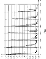
- the transmission and reception of the first six reflections from the ultrasound transducer 110 is shown in FIG Figure 2 shown.
- the ultrasound pulse 104 is emitted in the range from approximately 0 seconds to approximately 20 microseconds.
- the first reflection reaches the sensor after about 50 microseconds.
- the further reflections reach the ultrasound transducer 110 approximately every 50 microseconds.
- the control unit 120 determines the concentration of the component 102 of the fluid mixture 101 as a function of a measurement signal that originates from a received reflection 107, which occurs both at least once on the impedance jump 106 and at least one time the impedance jump 105 was reflected.
- the control unit 120 determines the concentration of the component 102 of the fluid mixture 101 as a function of a measurement signal which, according to the invention, originates from the eleventh or a subsequent received reflection.
- the total distance covered by the ultrasound pulse between the transmission and the reception of the reflection that is used by the control unit 120 results from the reflection that is used for the evaluation. If the second incoming reflection is not used according to the invention to determine the concentration of the constituent, the total path is four times the distance between the two impedance jumps 105 and 106. If the sixth incoming reflection is not used according to the invention for evaluation, the total path is twelve times the distance between the two two jumps in impedance 105 and 106. If the distance is, for example, 36 millimeters, the total path when evaluating the sixth reflection that has arrived is 432 millimeters.
- the total path is twice the distance between the two impedance jumps 105 and 106 times the number of the received reflection, which is used to determine the concentration of the component 102 of the fluid mixture 101.
- the control unit 120 measures the transit time which lies between the transmission of the ultrasound pulse 104 and the reception of the reflection 107.
- the reflection 107 is the received reflection, which is used as a measurement signal for determining the concentration of the component 102.
- the speed of sound in the fluid mixture 101 is determined from the measured transit time and the total path determined. The speed of sound is characteristic of the concentration of the component 102 in the fluid mixture 101, so that the concentration of the component can be determined from the speed of sound.
- the number of the received reflection 107 that is used to determine the concentration is predetermined.
- the total path is thus known, so that the concentration is determined as a function of the running time.
- the eleventh incoming reflection as a measurement signal to determine the concentration or a subsequent incoming reflection as a measurement signal
- the total path and thus the transit time of the ultrasound pulse is increased compared to a conventional method in which the first incoming reflection is used.
- the accuracy in determining the concentration is thus increased, since the runtime differences are greater with different concentrations of the constituent with a longer runtime.
- Figure 3 shows the arrangement 100 of FIG Figure 1 according to an embodiment not according to the invention.
- the jump in impedance 106 is not arranged on an opposite wall of the fluid space, but is a transition 111 of the fluid mixture 101 to another medium, in particular to air.
- the ultrasound transducer 110 and the control device 120 are also used to determine the concentration and also to determine the fill level of the fluid mixture 101 in the fluid space 103.
Description
- Die Erfindung betrifft ein Verfahren zur Ermittlung einer Konzentration eines Bestandteils eines Fluidgemisches. Weiterhin betrifft die Erfindung eine entsprechende Anordnung zur Ermittlung einer Konzentration eines Bestandteils eines Fluidgemisches.
- Mit Hilfe von Ultraschall ist es möglich, Flüssigkeiten anhand ihrer charakteristischen Schallgeschwindigkeit zu identifizieren (Impuls-Echo-Verfahren). Dazu wird die Laufzeit gemessen, die der Ultraschall für einen vorgegebenen Laufweg benötigt. Zur Unterscheidung von verschiedenen Konzentrationen eines Flüssigkeitsgemisches oder von verschiedenen Flüssigkeiten wird der Unterschied in der Laufzeit ausgewertet. Dieser Unterschied in der Laufzeit liegt im Mikrosekundenbereich. Je länger die Laufzeit desto größer ist der Unterschied in der Laufzeitdifferenz bei gleichen Konzentrationen.
- In Kraftfahrzeugen wird das Impuls-Echo-Verfahren beispielsweise zur Füllstandsmessung zur Ermittlung einer Menge eines Fluids in einem Tank verwendet. Weiterhin wird das Impuls-Echo-Verfahren verwendet um die Konzentration von Fluidgemischen, insbesondere Zwei-Komponenten-Gemischen, zu ermitteln.
- Um eine möglichst gute Auflösung in der Konzentration zu bekommen, ist es notwendig, einen möglichst langen Laufweg bereitzustellen.
- B. Henning, et. al. "In-line concentration measurement in complex liquids using ultrasonic sensors", Ultrasonics (2000) 799 - 803 sowie J.A. Bamberger, M.S. Greenwood "Measuring fluid and slurry density and solids concentration non-invasively", Ultrasonics, 42 (2004) 563 - 567 beschreiben jeweils ein Sensorsystem zur Charakterisierung von Flüssigkeitsmischungen, bei denen jeweils zur Messung ein Ultraschallimpuls abwechselnd an zwei gegenüberliegend angeordneten Schallwandlern reflektiert wird, und die Reflexionen ausgewertet werden.
- Es ist wünschenswert, ein Verfahren sowie eine entsprechende Anordnung anzugeben, das beziehungsweise die eine Verkleinerung des Bauraums sowie eine hohe Genauigkeit in der Auswertung ermöglichen.
- Die Erfindung zeichnet sich aus durch ein Verfahren entsprechend dem unabhängigen Anspruch 1 sowie eine Anordnung ensprechend dem unabhängigen Anspruch 2, zum Durchführen des Verfahrens eingerichtet ist.
- In einer Ausführungsform wird zur Ermittlung einer Konzentration eines Bestandteils eines Fluidgemisches in einem Fluidraum ein Ultraschallimpuls in das Fluidgemisch ausgesendet. Eine Reflexion des Ultraschallimpulses wird als Messsignal empfangen, nachdem der Ultraschallimpuls an mindestens zwei Impedanzsprüngen reflektiert wurde Die Konzentration des Bestandteils des Fluidgemisches wird in Abhängigkeit des Messsignals ermittelt.
- Die Geometrie des Fluidraums ist insbesondere durch die Einbausituation der Anordnung vorgegeben. Der Gesamtweg, der von dem Ultraschallimpuls zwischen dem Aussenden und dem Empfangen der Reflexion zurückgelegt wird, wird durch die Reflexion an mindestens zwei Impedanzsprüngen in der vorgegebenen Geometrie des Fluidraums verlängert. Damit verlängert sich auch die Laufzeit des Ultraschallimpulses zwischen dem Aussenden und dem Empfangen. Dadurch wird die Genauigkeit beim Ermitteln der Konzentration des Bestandteils des Fluidgemisches in der vorgegebenen Geometrie des Bauraums im Vergleich zu einer einfachen Reflexion an nur einem Impedanzsprung erhöht.
- Bei einer vorgegebenen Genauigkeit zur Ermittlung der Konzentration ist es möglich, den Fluidraum zu verkleinern und trotzdem die Genauigkeit beizubehalten.
- Gemäß der Erfindung wird die Reflexion empfangen, nachdem der Ultraschallimpuls an den mindestens zwei Impedanzsprüngen abwechselnd jeweils mehrmals reflektiert wurde, sodass der Ultraschallimpuls insgesamt mindestens elf Mal reflektiert wird. Es wird also die Reflexion empfangen, nachdem der Ultraschallimpuls an dem ersten Impedanzsprung der zwei Impedanzsprünge, an dem er zuerst reflektiert wird, sechs Mal reflektiert wurde, und jeweils zwischen zwei Reflexionen an dem ersten Impedanzsprung an dem zweiten Impedanzsprung der zwei Impedanzsprünge reflektiert wurde.
- Dadurch kann der Gesamtweg und damit die Laufzeit weiter verlängert werden, wodurch die Genauigkeit bei der Ermittlung der Konzentration weiter erhöht wird beziehungsweise der Fluidraum weiter verkleinerbar ist.
- Die Anordnung umfasst in Ausführungsformen einen Ultraschallwandler und eine Steuereinheit zum Betreiben des Ultraschallwandlers. Der Ultraschallwandler ist eingerichtet zum Aussenden des Ultraschallimpulses in das Fluidgemisch. Der Ultraschallwandler ist weiterhin eingerichtet zum Empfangen der Reflexion als Messsignal. Die Steuereinheit ist eingerichtet, ein Signal für den Ultraschallwandler bereitzustellen, so dass der Ultraschallwandler den Ultraschallimpuls aussendet. Weiterhin ist die Steuereinheit eingerichtet, in Abhängigkeit des Messsignals die Konzentration des Bestandteils des Fluidgemisches zu ermitteln.
- Die zwei Impedanzsprünge sind so angeordnet, dass der Ultraschallimpuls an dem ersten Impedanzsprung so reflektiert wird, dass der Ultraschallimpuls nach der Reflexion an dem Impedanzsprung auf den weiteren Impedanzsprung trifft. Die mindestens zwei Impedanzsprünge sind weiterhin so angeordnet, dass der Ultraschallimpuls an dem weiteren Impedanzsprung so reflektiert wird, dass der Ultraschallimpuls nach der Reflexion an dem weiteren Impedanzsprung wiederum auf den Impedanzsprung trifft. Dadurch ist es möglich, dass bei zwei Impedanzsprüngen der Ultraschall öfters als zwei Mal reflektiert wird, wodurch der Gesamtweg und damit die Laufzeit des Ultraschallimpulses verlängerbar ist.
- Insbesondere ist der weitere Impedanzsprung im Fluidraum örtlich in einem Bereich des Ultraschallwandlers angeordnet. Beispielsweise ist der weitere Impedanzsprung an einer Oberfläche des Ultraschallwandlers, so dass der Ultraschallimpuls an dem Ultraschallwandler reflektiert wird.
- Weitere Vorteile, Merkmale und Weiterbildungen ergeben sich aus dem nachfolgenden in Verbindung mit der Figur erläuterten Beispiel. Die dargestellten Elemente und deren Größenverhältnis zueinander sind grundsätzlich nicht als maßstabsgerecht anzusehen.
- Es zeigen:
- Figur 1
- eine schematische Darstellung einer Anordnung gemäß einer Ausführungsform,
- Figur 2
- den Verlauf der empfangenen Reflexionen und
- Figur 3
- eine schematische Darstellung einer Anordnung gemäß einer weiteren Ausführungsform.
-
Figur 1 zeigt eine schematische Darstellung einer Anordnung 100. Die Anordnung 100 umfasst einen Ultraschallwandler 110. Die Anordnung 100 umfasst weiterhin eine Steuereinheit 120 zum Betreiben des Ultraschallwandlers 110. - Der Ultraschallwandler 110 ist eine Ultraschallquelle, die ebenfalls als Ultraschallempfänger dient. In Ausführungsformen sind die Ultraschallquelle und der Ultraschallempfänger getrennte Bauelemente.
- Die Steuereinheit 120 ist mit dem Ultraschallwandler 110 gekoppelt. Die Steuereinheit 120 ist eingerichtet, Signale zum Betreiben des Ultraschallwandlers 110 bereitzustellen, so dass der Ultraschallwandler 110 in Abhängigkeit der Signale einen Ultraschallimpuls aussendet. Weiterhin ist die Steuereinheit 120 eingerichtet, Messsignale von dem Ultraschallwandler zu empfangen.
- Der Ultraschallwandler 110 ist an einem Fluidraum 103 angeordnet. Der Fluidraum ist von Wänden 109 umgeben. Der Fluidraum ist zumindest teilweise mit einem Fluidgemisch 101 gefüllt. Das Fluidgemisch 101 umfasst beispielsweise zwei Bestandteile. Die Konzentration eines Bestandteils 102 der zwei Bestandteile wird ermittelt. Beispielsweise ist das Fluidgemisch eine Mischung aus Harnstoff und Wasser, die zur Nachbehandlung von Abgasen eines Kraftfahrzeugs in einem SCR-Katalysator verwendet wird (SCR: Selektive Katalytische Reduktion, englisch: selective catalytic reduction) . Der Bestandteil 102 des Fluidgemisches 101 ist in diesem Beispiel der Harnstoff.
- In dem Fluidraum 103 sind zwei Impedanzsprünge 105 und 106 angeordnet. Der erste Impedanzsprung 105 ist im gezeigten Ausführungsbeispiel die dem Fluidraum 103 zugewandte Oberfläche des Ultraschallwandlers 110. Der zweite Impedanzsprung 106 ist im Fluidraum gegenüber dem ersten Impedanzsprung 105 angeordnet, so dass ein Ultraschallimpuls 104, der von dem Ultraschallwandler 110 ausgesendet wird, zwischen den beiden Impedanzsprüngen 105 und 106 hin und her reflektiert wird.
- Der Ultraschallwandler 110 ist an einer der Wände 109 angeordnet und sendet den Ultraschallimpuls durch die Wand in das Fluidgemisch 101.
- Von dem Ultraschallwandler 110 wird der Ultraschallimpuls 104 ausgesendet, der an dem Impedanzsprung 106 zurück zu dem Ultraschallwandler 110 beziehungsweise dem Impedanzsprung 105 reflektiert wird. Als Impedanzsprung 106 dient erfindungsgemäß ein an der dem Ultraschallwandler 110 gegenüberliegenden Wand 109 des Fluidraums 103 zur, Verstärkung der Reflexion angeordneter Schallreflektor 108 .
- Nachdem der Ultraschallimpuls an dem Impedanzsprung 106 reflektiert wurde, wird er zu dem Impedanzsprung 105 reflektiert. Der Ultraschallimpuls wird an dem Impedanzsprung 105 so reflektiert, dass er wieder auf den Impedanzsprung 106 trifft, an dem er ein weiteres Mal reflektiert wird. Daraufhin trifft der Ultraschallimpuls ein zweites Mal auf den Ultraschallwandler 110. Dies wiederholt sich, bis der Ultraschallimpuls abgeklungen ist.
- Das Aussenden und das Empfangen der ersten sechs Reflexionen von dem Ultraschallwandler 110 ist in
Figur 2 dargestellt. Im Bereich von etwa 0 Sekunden bis etwa 20 Mikrosekunden wird der Ultraschallimpuls 104 aussendet. Die erste Reflexion erreicht den Sensor nach circa 50 Mikrosekunden. Die weiteren Reflexionen erreichen den Ultraschallwandler 110 etwa alle 50 Mikrosekunden. Die Steuereinheit 120 ermittelt die Konzentration des Bestandteils 102 des Fluidgemisches 101 in Abhängigkeit eines Messsignals, das aus einer empfangenen Reflexion 107 stammt, die sowohl mindestens ein Mal an dem Impedanzsprung 106 als auch mindesten ein Mals an dem Impedanzsprung 105 reflektiert wurde. Die Steuereinheit 120 ermittelt die Konzentration des Bestandteils 102 des Fluidgemisches 101 in Abhängigkeit eines Messsignals, das erfindungsgemäß aus der elften oder einer nachfolgenden empfangenen Reflexion stammt. - Die Gesamtwegstrecke, die der Ultraschallimpuls zwischen dem Aussenden und dem Empfangen der Reflexion, die von der Steuereinheit 120 verwendet wird, zurücklegt, ergibt sich aus der Reflexion, die zur Auswertung verwendet wird. Wird nicht erfindungsgemäß die zweite eintreffende Reflexion zur Ermittlung der Konzentration des Bestandteils verwendet, ist der Gesamtweg das Vierfache des Abstands zwischen den beiden Impedanzsprüngen 105 und 106. Wird nicht erfindungsgemäß die sechste eintreffende Reflexion zur Auswertung verwendet, ist der Gesamtweg das Zwölffache des Abstands zwischen den beiden Impedanzsprüngen 105 und 106. Beträgt der Abstand beispielsweise 36 Millimeter, beträgt der Gesamtweg bei einer Auswertung der sechsten eingetroffenen Reflexion 432 Millimeter.
- Allgemein ist der Gesamtweg das Zweifache des Abstandes zwischen den beiden Impedanzsprüngen 105 und 106 mal der Nummer der empfangenen Reflexion, die zur Ermittlung der Konzentration des Bestandteils 102 des Fluidgemisches 101 verwendet wird.
- Von der Steuereinheit 120 wird die Laufzeit gemessen, die zwischen dem Aussenden des Ultraschallimpulses 104 und dem Empfangen der Reflexion 107 liegt. Die Reflexion 107 ist die empfangene Reflexion, die als Messsignal zur Ermittlung der Konzentration des Bestandteils 102 verwendet wird. Aus der gemessenen Laufzeit und dem ermittelten Gesamtweg wird die Schallgeschwindigkeit in dem Fluidgemisch 101 ermittelt. Die Schallgeschwindigkeit ist charakteristisch für die Konzentration des Bestandteils 102 in dem Fluidgemisch 101, so dass aus der Schallgeschwindigkeit die Konzentration des Bestandteils ermittelbar ist.
- In Ausführungsformen ist die Nummer der empfangen Reflexion 107, die Ermittlung der Konzentration verwendet wird, vorgegeben. Damit ist der Gesamtweg bekannt, so dass die Konzentration in Abhängigkeit der Laufzeit ermittelt wird.
- Durch die Verwendung der elften eintreffenden Reflexion als Messsignal zur Ermittlung der Konzentration oder einer nachfolgenden eintreffenden Reflexion als Messsignal wird der Gesamtweg und damit die Laufzeit des Ultraschallimpulses erhöht im Vergleich zu einem herkömmlichen Verfahren, bei dem die erste eintreffende Reflexion verwendet wird. Somit ist die Genauigkeit beim Ermitteln der Konzentration erhöht, da mit einer längeren Laufzeit die Laufzeitunterschiede bei unterschiedlichen Konzentrationen des Bestandteils größer sind.
- Bei gleichbleibender vorgegebener Genauigkeit ist es möglich, durch die Auswertung der zweite oder einer späteren eintreffenden Reflexion den Bauraum des Fluidraums 103 zu verkleinern, beispielsweise den Abstand zwischen den beiden Impedanzsprüngen 105 und 106 zu verringern.
-
Figur 3 zeigt die Anordnung 100 derFigur 1 gemäß einer nicht erfindungsgemäßen Ausführungsform. Im Unterschied zuFigur 1 ist der Impedanzsprung 106 nicht an einer gegenüberliegenden Wand des Fluidraums angeordnet, sondern ist ein Übergang 111 des Fluidgemisches 101 zu einem anderen Medium, insbesondere zu Luft. Gemäß diesem Ausführungsbeispiel werden der Ultraschallwandler 110 und die Steuereinrichtung 120 zusätzlich zur Konzentrationsermittlung auch zur Ermittlung des Füllstandes des Fluidgemisches 101 in dem Fluidraum 103 verwendet.
Claims (7)
- Verfahren zur Ermittlung einer Konzentration eines Bestandteils (102) eines Fluidgemisches (101) in einem Fluidraum (103), umfassend:- Aussenden eines Ultraschallimpulses (104) in das Fluidgemisch (101) mittels eines Ultraschallwandlers (110),- Empfangen einer Reflexion (107) des Ultraschallimpulses (104) als Messsignal, nachdem der Ultraschallimpuls (104) an mindestens zwei Impedanzsprüngen (105; 106) reflektiert wurde,- Empfangen der Reflexion (107), nachdem der Ultraschallimpuls (104) an den mindestens zwei Impedanzsprüngen (105; 106) abwechselnd insgesamt mindestens 11 Mal reflektiert wurde, wobei die Reflexion (107) zur Verstärkung an einem Schallreflektor (108) reflektiert wurde und der Ultraschallwandler (110) und der Schallreflektor (108) an gegenüberliegenden Wänden (109) des Fluidraums (103) angeordnet. sind, und- Ermitteln der Konzentration des Bestandteils (102) des Fluidgemisches (101) in Abhängigkeit des Messsignals.
- Anordnung aus einem Ultraschallwandler (110) und einem Schallreflektor (108) zur Reflexionsverstärkung, die an gegenüberliegenden Wänden (109) eines Fluidraums (103) angeordnet sind, und einer Steuereinheit (120) zum Betreiben des Ultraschallwandlers (110), wobei die Anordnung eingerichtet ist zum Durchführen eines Verfahrens gemäß Anspruch 1.
- Anordnung nach Anspruch 2, bei der die mindestens zwei Impedanzsprünge (105; 106) so angeordnet sind, dass der Ultraschallimpuls (104) an dem Impedanzsprung (106) so reflektiert wird, dass der Ultraschallimpuls (104) nach der Reflexion an dem Impedanzsprung (106) auf den weiteren Impedanzsprung (105) trifft.
- Anordnung nach Anspruch 2 oder 3, bei der die mindestens zwei Impedanzsprünge (105; 106) so angeordnet sind, dass der Ultraschallimpuls (104) an dem weiteren Impedanzsprung (105) so reflektiert wird, dass der Ultraschallimpuls (104) nach der Reflexion an dem weiteren Impedanzsprung (105) wiederum auf den Impedanzsprung (106) trifft.
- Anordnung nach einem der Ansprüche 2 bis 4, bei der der Ultraschallimpuls (104) von dem Ultraschallwandler (110) ausgesendet wird, der an dem Fluidraum (103) angeordnet ist, und die Reflexion (107) von dem Ultraschallwandler (110) empfangen wird, wobei der weitere Impedanzsprung (105) im Fluidraum örtlich in einem Bereich des Ultraschallwandlers (110) angeordnet ist.
- Anordnung nach einem der Ansprüche 2 bis 5, bei der zwischen dem Ultraschallwandler (110) und dem Impedanzsprung (106) ein Abstand ist und die Steuereinheit (120) eingerichtet ist, die Konzentration des Bestandteils (102) des Fluidgemisches (101) in Abhängigkeit von einem Gesamtweg zu ermitteln, der sich ergibt aus dem Abstand und der Anzahl der Reflexionen an den mindestens zwei Impedanzsprüngen (105; 106).
- Anordnung nach einem der Ansprüche 2 bis 6, bei der Ultraschallwandler (110) so angeordnet ist, dass der Ultraschallimpuls (104) an einer Wand (109) des Fluidraums (103) reflektiert wird.
Applications Claiming Priority (2)
| Application Number | Priority Date | Filing Date | Title |
|---|---|---|---|
| DE102011012992A DE102011012992A1 (de) | 2011-03-03 | 2011-03-03 | Anordnung und Verfahren zur Ermittlung einer Konzentration eines Bestandteils eines Fluidgemisches |
| PCT/EP2012/053510 WO2012117052A1 (de) | 2011-03-03 | 2012-03-01 | Anordnung und verfahren zur ermittlung einer konzentration eines bestandteils eines fluidgemisches |
Publications (2)
| Publication Number | Publication Date |
|---|---|
| EP2681519A1 EP2681519A1 (de) | 2014-01-08 |
| EP2681519B1 true EP2681519B1 (de) | 2020-08-05 |
Family
ID=45922650
Family Applications (1)
| Application Number | Title | Priority Date | Filing Date |
|---|---|---|---|
| EP12711357.9A Active EP2681519B1 (de) | 2011-03-03 | 2012-03-01 | Anordnung und verfahren zur ermittlung einer konzentration eines bestandteils eines fluidgemisches |
Country Status (5)
| Country | Link |
|---|---|
| US (1) | US20140041442A1 (de) |
| EP (1) | EP2681519B1 (de) |
| CN (1) | CN103403506B (de) |
| DE (1) | DE102011012992A1 (de) |
| WO (1) | WO2012117052A1 (de) |
Families Citing this family (8)
| Publication number | Priority date | Publication date | Assignee | Title |
|---|---|---|---|---|
| JP6049058B2 (ja) * | 2012-10-09 | 2016-12-21 | 株式会社サンエー | 流動体状態識別装置 |
| US10254240B2 (en) * | 2014-06-17 | 2019-04-09 | Littelfuse, Inc. | Pulsed wave guide liquid quality measurement |
| DE102014213216A1 (de) * | 2014-07-08 | 2016-01-28 | Continental Automotive Gmbh | Verfahren und Vorrichtung zum Bestimmen einer Konzentration eines Bestandteils eines Fluidgemischs in einem Fluidraum |
| US20160363473A1 (en) * | 2015-06-11 | 2016-12-15 | Hyundai Motor Company | System for inspecting urea quality and method for the same |
| CN105486746A (zh) * | 2016-01-14 | 2016-04-13 | 济南齐力光电技术有限公司 | 一种乳液成分分析装置及乳液检测方法 |
| US10571431B2 (en) * | 2017-06-02 | 2020-02-25 | Ssi Technologies, Llc | Combination sensor |
| JP7006354B2 (ja) * | 2018-02-16 | 2022-01-24 | 富士電機株式会社 | 計測装置 |
| EP3822660A1 (de) * | 2019-11-13 | 2021-05-19 | ABB Schweiz AG | Integritätserkennungssystem für einen ultraschallwandler |
Family Cites Families (13)
| Publication number | Priority date | Publication date | Assignee | Title |
|---|---|---|---|---|
| US4754650A (en) * | 1983-07-29 | 1988-07-05 | Panametrics, Inc. | Apparatus and methods for measuring fluid flow parameters |
| GB9502087D0 (en) * | 1995-02-02 | 1995-03-22 | Croma Dev Ltd | Improvements relating to pulse echo distance measurement |
| US5650571A (en) * | 1995-03-13 | 1997-07-22 | Freud; Paul J. | Low power signal processing and measurement apparatus |
| US5793705A (en) * | 1996-09-18 | 1998-08-11 | International Business Machines Corporation | Ultrasonic liquid level gauge for tanks subject to movement and vibration |
| JPH11118774A (ja) * | 1997-10-14 | 1999-04-30 | Toyota Motor Corp | オイル劣化センサ |
| NL1009485C2 (nl) * | 1998-06-24 | 2000-01-11 | Wilhelm Henricus Jurriaan Van | Akoestische looptijdmeting. |
| DE10224294A1 (de) * | 2002-05-31 | 2004-01-15 | systec Controls Meß- und Regeltechnik GmbH | Verfahren zur Ultraschall-Laufzeit-Mengenmessung |
| US7098669B2 (en) * | 2003-10-01 | 2006-08-29 | Flowline, Inc. | Depth determining system |
| DE102005025671B3 (de) * | 2005-06-03 | 2006-12-21 | Siemens Ag | Verfahren und Vorrichtung zur Messung der spezifischen Dichte eines gasförmigen oder flüssigen Mediums |
| US7542870B2 (en) * | 2006-02-28 | 2009-06-02 | Ssi Technologies, Inc. | Immersed fuel level sensor |
| DE102008048582A1 (de) * | 2008-09-23 | 2010-03-25 | Endress + Hauser Gmbh + Co. Kg | Mit Mikrowellen arbeitendes Füllstandsmessgerät |
| US8583387B2 (en) * | 2010-06-04 | 2013-11-12 | Ssi Technologies, Inc. | Ultrasonic level, on-board diagnostic assessment |
| US8919194B2 (en) * | 2012-09-05 | 2014-12-30 | Simmonds Precision Products, Inc. | Liquid level gauging system with bubble shedding reflectors |
-
2011
- 2011-03-03 DE DE102011012992A patent/DE102011012992A1/de not_active Withdrawn
-
2012
- 2012-03-01 CN CN201280011327.8A patent/CN103403506B/zh not_active Expired - Fee Related
- 2012-03-01 US US14/002,977 patent/US20140041442A1/en not_active Abandoned
- 2012-03-01 EP EP12711357.9A patent/EP2681519B1/de active Active
- 2012-03-01 WO PCT/EP2012/053510 patent/WO2012117052A1/de active Application Filing
Non-Patent Citations (1)
| Title |
|---|
| None * |
Also Published As
| Publication number | Publication date |
|---|---|
| CN103403506A (zh) | 2013-11-20 |
| DE102011012992A1 (de) | 2012-09-06 |
| CN103403506B (zh) | 2016-12-07 |
| EP2681519A1 (de) | 2014-01-08 |
| WO2012117052A1 (de) | 2012-09-07 |
| US20140041442A1 (en) | 2014-02-13 |
Similar Documents
| Publication | Publication Date | Title |
|---|---|---|
| EP2681519B1 (de) | Anordnung und verfahren zur ermittlung einer konzentration eines bestandteils eines fluidgemisches | |
| EP3049772B1 (de) | Flüssigkeitstank mit einem ultraschallsensor | |
| EP2440888B1 (de) | Verfahren zum messen einer messgrösse | |
| DE19842250A1 (de) | Verfahren zur Bestimmung des Abstandes zwischen einem Objekt und einer sich örtlich verändernden Einrichtung, insbesondere einem Kraftfahrzeug | |
| EP3169884A1 (de) | Verfahren zur bestimmung des füllstands in einem tank | |
| DE102011086774A1 (de) | Vorrichtung und Verfahren zur gleichzeitigen Füllstandsbestimmung und Qualitätsbestimmung einer Reduktionsmittellösung | |
| DE102011013687B4 (de) | Verfahren zur Kalibrierung eines Füllstandsensors | |
| WO2016005343A1 (de) | Vorrichtung zum bestimmung einer schallgeschwindigkeit eines schallsignals in einem fluid | |
| EP1554548A1 (de) | Ultraschall-laufzeit-mengenmessung zum ermitteln der konzentration von partikeln in einem strömenden fluid | |
| DE4306193B4 (de) | Füllstandssensor | |
| EP3756000A1 (de) | Vorrichtung zur qualitätsbestimmung, tankvorrichtung | |
| EP3343185B1 (de) | Ultraschalldurchflussmessgerät und verfahren zur messung des durchflusses | |
| EP2035858A1 (de) | Ultraschallsensor, fahrzeug mit ultraschallsensor und verfahren zum betreiben des ultraschallsensors | |
| EP3405779B1 (de) | Verfahren zur akustischen bestimmung von eigenschaften eines mediums und vorrichtung zur akustischen bestimmung von eigenschaften eines mediums mit reflexionselement | |
| DE10309861B4 (de) | Verfahren und Vorrichtung zur Bestimmung wenigstens einer chemischen oder physikalischen Eigenschaft einer Flüssigkeit bei Füllstandsmessung in einem Behälter | |
| EP1859236B1 (de) | Vorrichtung zum messen des füllstandes einer flüssigkeit in einem behälter mit einem ultraschallwandler | |
| DE102011119673A1 (de) | Akustischer Wellenleiter-Sensor zur Bestimmung von Eigenschaften einer Flüssigkeit sowie seine Verwendung | |
| DE102012211848B4 (de) | Füllstandmessung | |
| DE102009035983A1 (de) | Verfahren und Vorrichtung zur Bestimmung einer Durchflussmenge eines Fluids | |
| EP3809102A1 (de) | Anordnung und verfahren zum feststellen eines mindestfüllstands eines fluids in einem fluidbehälter | |
| DE10035624A1 (de) | Vorrichtung und Verfahren zur Fluiddiagnose | |
| DE19643956A1 (de) | Anordnung zur Kontrolle des Füllstandes | |
| DE102006017284A1 (de) | Vorrichtung zur Messung des Füllstandes einer Flüssigkeit in einem Behälter | |
| EP0158856A2 (de) | Verfahren zur Ultraschallprüfung ferritischer Bauteile mit einer Plattierung | |
| DE102017117357A1 (de) | Verfahren zum Bestimmen eines räumlichen Abstands zwischen einem Ultraschallsensor und einem Hindernis |
Legal Events
| Date | Code | Title | Description |
|---|---|---|---|
| PUAI | Public reference made under article 153(3) epc to a published international application that has entered the european phase |
Free format text: ORIGINAL CODE: 0009012 |
|
| 17P | Request for examination filed |
Effective date: 20131004 |
|
| AK | Designated contracting states |
Kind code of ref document: A1 Designated state(s): AL AT BE BG CH CY CZ DE DK EE ES FI FR GB GR HR HU IE IS IT LI LT LU LV MC MK MT NL NO PL PT RO RS SE SI SK SM TR |
|
| DAX | Request for extension of the european patent (deleted) | ||
| STAA | Information on the status of an ep patent application or granted ep patent |
Free format text: STATUS: EXAMINATION IS IN PROGRESS |
|
| 17Q | First examination report despatched |
Effective date: 20180622 |
|
| GRAP | Despatch of communication of intention to grant a patent |
Free format text: ORIGINAL CODE: EPIDOSNIGR1 |
|
| STAA | Information on the status of an ep patent application or granted ep patent |
Free format text: STATUS: GRANT OF PATENT IS INTENDED |
|
| INTG | Intention to grant announced |
Effective date: 20200310 |
|
| RAP1 | Party data changed (applicant data changed or rights of an application transferred) |
Owner name: VITESCO TECHNOLOGIES GMBH |
|
| GRAS | Grant fee paid |
Free format text: ORIGINAL CODE: EPIDOSNIGR3 |
|
| GRAA | (expected) grant |
Free format text: ORIGINAL CODE: 0009210 |
|
| STAA | Information on the status of an ep patent application or granted ep patent |
Free format text: STATUS: THE PATENT HAS BEEN GRANTED |
|
| AK | Designated contracting states |
Kind code of ref document: B1 Designated state(s): AL AT BE BG CH CY CZ DE DK EE ES FI FR GB GR HR HU IE IS IT LI LT LU LV MC MK MT NL NO PL PT RO RS SE SI SK SM TR |
|
| REG | Reference to a national code |
Ref country code: GB Ref legal event code: FG4D Free format text: NOT ENGLISH |
|
| REG | Reference to a national code |
Ref country code: CH Ref legal event code: EP |
|
| REG | Reference to a national code |
Ref country code: AT Ref legal event code: REF Ref document number: 1299355 Country of ref document: AT Kind code of ref document: T Effective date: 20200815 |
|
| REG | Reference to a national code |
Ref country code: DE Ref legal event code: R096 Ref document number: 502012016264 Country of ref document: DE |
|
| REG | Reference to a national code |
Ref country code: IE Ref legal event code: FG4D Free format text: LANGUAGE OF EP DOCUMENT: GERMAN |
|
| REG | Reference to a national code |
Ref country code: LT Ref legal event code: MG4D |
|
| REG | Reference to a national code |
Ref country code: NL Ref legal event code: MP Effective date: 20200805 |
|
| PG25 | Lapsed in a contracting state [announced via postgrant information from national office to epo] |
Ref country code: ES Free format text: LAPSE BECAUSE OF FAILURE TO SUBMIT A TRANSLATION OF THE DESCRIPTION OR TO PAY THE FEE WITHIN THE PRESCRIBED TIME-LIMIT Effective date: 20200805 Ref country code: PT Free format text: LAPSE BECAUSE OF FAILURE TO SUBMIT A TRANSLATION OF THE DESCRIPTION OR TO PAY THE FEE WITHIN THE PRESCRIBED TIME-LIMIT Effective date: 20201207 Ref country code: HR Free format text: LAPSE BECAUSE OF FAILURE TO SUBMIT A TRANSLATION OF THE DESCRIPTION OR TO PAY THE FEE WITHIN THE PRESCRIBED TIME-LIMIT Effective date: 20200805 Ref country code: LT Free format text: LAPSE BECAUSE OF FAILURE TO SUBMIT A TRANSLATION OF THE DESCRIPTION OR TO PAY THE FEE WITHIN THE PRESCRIBED TIME-LIMIT Effective date: 20200805 Ref country code: SE Free format text: LAPSE BECAUSE OF FAILURE TO SUBMIT A TRANSLATION OF THE DESCRIPTION OR TO PAY THE FEE WITHIN THE PRESCRIBED TIME-LIMIT Effective date: 20200805 Ref country code: BG Free format text: LAPSE BECAUSE OF FAILURE TO SUBMIT A TRANSLATION OF THE DESCRIPTION OR TO PAY THE FEE WITHIN THE PRESCRIBED TIME-LIMIT Effective date: 20201105 Ref country code: FI Free format text: LAPSE BECAUSE OF FAILURE TO SUBMIT A TRANSLATION OF THE DESCRIPTION OR TO PAY THE FEE WITHIN THE PRESCRIBED TIME-LIMIT Effective date: 20200805 Ref country code: GR Free format text: LAPSE BECAUSE OF FAILURE TO SUBMIT A TRANSLATION OF THE DESCRIPTION OR TO PAY THE FEE WITHIN THE PRESCRIBED TIME-LIMIT Effective date: 20201106 Ref country code: NO Free format text: LAPSE BECAUSE OF FAILURE TO SUBMIT A TRANSLATION OF THE DESCRIPTION OR TO PAY THE FEE WITHIN THE PRESCRIBED TIME-LIMIT Effective date: 20201105 |
|
| PG25 | Lapsed in a contracting state [announced via postgrant information from national office to epo] |
Ref country code: NL Free format text: LAPSE BECAUSE OF FAILURE TO SUBMIT A TRANSLATION OF THE DESCRIPTION OR TO PAY THE FEE WITHIN THE PRESCRIBED TIME-LIMIT Effective date: 20200805 Ref country code: LV Free format text: LAPSE BECAUSE OF FAILURE TO SUBMIT A TRANSLATION OF THE DESCRIPTION OR TO PAY THE FEE WITHIN THE PRESCRIBED TIME-LIMIT Effective date: 20200805 Ref country code: RS Free format text: LAPSE BECAUSE OF FAILURE TO SUBMIT A TRANSLATION OF THE DESCRIPTION OR TO PAY THE FEE WITHIN THE PRESCRIBED TIME-LIMIT Effective date: 20200805 Ref country code: PL Free format text: LAPSE BECAUSE OF FAILURE TO SUBMIT A TRANSLATION OF THE DESCRIPTION OR TO PAY THE FEE WITHIN THE PRESCRIBED TIME-LIMIT Effective date: 20200805 Ref country code: IS Free format text: LAPSE BECAUSE OF FAILURE TO SUBMIT A TRANSLATION OF THE DESCRIPTION OR TO PAY THE FEE WITHIN THE PRESCRIBED TIME-LIMIT Effective date: 20201205 |
|
| PG25 | Lapsed in a contracting state [announced via postgrant information from national office to epo] |
Ref country code: DK Free format text: LAPSE BECAUSE OF FAILURE TO SUBMIT A TRANSLATION OF THE DESCRIPTION OR TO PAY THE FEE WITHIN THE PRESCRIBED TIME-LIMIT Effective date: 20200805 Ref country code: EE Free format text: LAPSE BECAUSE OF FAILURE TO SUBMIT A TRANSLATION OF THE DESCRIPTION OR TO PAY THE FEE WITHIN THE PRESCRIBED TIME-LIMIT Effective date: 20200805 Ref country code: CZ Free format text: LAPSE BECAUSE OF FAILURE TO SUBMIT A TRANSLATION OF THE DESCRIPTION OR TO PAY THE FEE WITHIN THE PRESCRIBED TIME-LIMIT Effective date: 20200805 Ref country code: SM Free format text: LAPSE BECAUSE OF FAILURE TO SUBMIT A TRANSLATION OF THE DESCRIPTION OR TO PAY THE FEE WITHIN THE PRESCRIBED TIME-LIMIT Effective date: 20200805 Ref country code: RO Free format text: LAPSE BECAUSE OF FAILURE TO SUBMIT A TRANSLATION OF THE DESCRIPTION OR TO PAY THE FEE WITHIN THE PRESCRIBED TIME-LIMIT Effective date: 20200805 |
|
| REG | Reference to a national code |
Ref country code: DE Ref legal event code: R097 Ref document number: 502012016264 Country of ref document: DE |
|
| PG25 | Lapsed in a contracting state [announced via postgrant information from national office to epo] |
Ref country code: AL Free format text: LAPSE BECAUSE OF FAILURE TO SUBMIT A TRANSLATION OF THE DESCRIPTION OR TO PAY THE FEE WITHIN THE PRESCRIBED TIME-LIMIT Effective date: 20200805 |
|
| PLBE | No opposition filed within time limit |
Free format text: ORIGINAL CODE: 0009261 |
|
| STAA | Information on the status of an ep patent application or granted ep patent |
Free format text: STATUS: NO OPPOSITION FILED WITHIN TIME LIMIT |
|
| PG25 | Lapsed in a contracting state [announced via postgrant information from national office to epo] |
Ref country code: SK Free format text: LAPSE BECAUSE OF FAILURE TO SUBMIT A TRANSLATION OF THE DESCRIPTION OR TO PAY THE FEE WITHIN THE PRESCRIBED TIME-LIMIT Effective date: 20200805 |
|
| 26N | No opposition filed |
Effective date: 20210507 |
|
| PG25 | Lapsed in a contracting state [announced via postgrant information from national office to epo] |
Ref country code: IT Free format text: LAPSE BECAUSE OF FAILURE TO SUBMIT A TRANSLATION OF THE DESCRIPTION OR TO PAY THE FEE WITHIN THE PRESCRIBED TIME-LIMIT Effective date: 20200805 |
|
| PG25 | Lapsed in a contracting state [announced via postgrant information from national office to epo] |
Ref country code: SI Free format text: LAPSE BECAUSE OF FAILURE TO SUBMIT A TRANSLATION OF THE DESCRIPTION OR TO PAY THE FEE WITHIN THE PRESCRIBED TIME-LIMIT Effective date: 20200805 |
|
| REG | Reference to a national code |
Ref country code: DE Ref legal event code: R119 Ref document number: 502012016264 Country of ref document: DE |
|
| PG25 | Lapsed in a contracting state [announced via postgrant information from national office to epo] |
Ref country code: MC Free format text: LAPSE BECAUSE OF FAILURE TO SUBMIT A TRANSLATION OF THE DESCRIPTION OR TO PAY THE FEE WITHIN THE PRESCRIBED TIME-LIMIT Effective date: 20200805 |
|
| REG | Reference to a national code |
Ref country code: CH Ref legal event code: PL |
|
| GBPC | Gb: european patent ceased through non-payment of renewal fee |
Effective date: 20210301 |
|
| REG | Reference to a national code |
Ref country code: BE Ref legal event code: MM Effective date: 20210331 |
|
| PG25 | Lapsed in a contracting state [announced via postgrant information from national office to epo] |
Ref country code: LU Free format text: LAPSE BECAUSE OF NON-PAYMENT OF DUE FEES Effective date: 20210301 Ref country code: LI Free format text: LAPSE BECAUSE OF NON-PAYMENT OF DUE FEES Effective date: 20210331 Ref country code: CH Free format text: LAPSE BECAUSE OF NON-PAYMENT OF DUE FEES Effective date: 20210331 Ref country code: GB Free format text: LAPSE BECAUSE OF NON-PAYMENT OF DUE FEES Effective date: 20210301 Ref country code: IE Free format text: LAPSE BECAUSE OF NON-PAYMENT OF DUE FEES Effective date: 20210301 Ref country code: FR Free format text: LAPSE BECAUSE OF NON-PAYMENT OF DUE FEES Effective date: 20210331 Ref country code: DE Free format text: LAPSE BECAUSE OF NON-PAYMENT OF DUE FEES Effective date: 20211001 |
|
| REG | Reference to a national code |
Ref country code: AT Ref legal event code: MM01 Ref document number: 1299355 Country of ref document: AT Kind code of ref document: T Effective date: 20210301 |
|
| PG25 | Lapsed in a contracting state [announced via postgrant information from national office to epo] |
Ref country code: BE Free format text: LAPSE BECAUSE OF NON-PAYMENT OF DUE FEES Effective date: 20210331 |
|
| PG25 | Lapsed in a contracting state [announced via postgrant information from national office to epo] |
Ref country code: AT Free format text: LAPSE BECAUSE OF NON-PAYMENT OF DUE FEES Effective date: 20210301 |
|
| PG25 | Lapsed in a contracting state [announced via postgrant information from national office to epo] |
Ref country code: HU Free format text: LAPSE BECAUSE OF FAILURE TO SUBMIT A TRANSLATION OF THE DESCRIPTION OR TO PAY THE FEE WITHIN THE PRESCRIBED TIME-LIMIT; INVALID AB INITIO Effective date: 20120301 Ref country code: CY Free format text: LAPSE BECAUSE OF FAILURE TO SUBMIT A TRANSLATION OF THE DESCRIPTION OR TO PAY THE FEE WITHIN THE PRESCRIBED TIME-LIMIT Effective date: 20200805 |