EP2680406A2 - Motor - Google Patents
Motor Download PDFInfo
- Publication number
- EP2680406A2 EP2680406A2 EP13173468.3A EP13173468A EP2680406A2 EP 2680406 A2 EP2680406 A2 EP 2680406A2 EP 13173468 A EP13173468 A EP 13173468A EP 2680406 A2 EP2680406 A2 EP 2680406A2
- Authority
- EP
- European Patent Office
- Prior art keywords
- busbar
- motor
- terminal
- coil
- stator
- Prior art date
- Legal status (The legal status is an assumption and is not a legal conclusion. Google has not performed a legal analysis and makes no representation as to the accuracy of the status listed.)
- Granted
Links
Images




Classifications
-
- H—ELECTRICITY
- H02—GENERATION; CONVERSION OR DISTRIBUTION OF ELECTRIC POWER
- H02K—DYNAMO-ELECTRIC MACHINES
- H02K29/00—Motors or generators having non-mechanical commutating devices, e.g. discharge tubes or semiconductor devices
-
- H—ELECTRICITY
- H02—GENERATION; CONVERSION OR DISTRIBUTION OF ELECTRIC POWER
- H02K—DYNAMO-ELECTRIC MACHINES
- H02K5/00—Casings; Enclosures; Supports
- H02K5/04—Casings or enclosures characterised by the shape, form or construction thereof
- H02K5/22—Auxiliary parts of casings not covered by groups H02K5/06-H02K5/20, e.g. shaped to form connection boxes or terminal boxes
- H02K5/225—Terminal boxes or connection arrangements
-
- H—ELECTRICITY
- H02—GENERATION; CONVERSION OR DISTRIBUTION OF ELECTRIC POWER
- H02K—DYNAMO-ELECTRIC MACHINES
- H02K3/00—Details of windings
- H02K3/46—Fastening of windings on the stator or rotor structure
- H02K3/52—Fastening salient pole windings or connections thereto
- H02K3/521—Fastening salient pole windings or connections thereto applicable to stators only
- H02K3/522—Fastening salient pole windings or connections thereto applicable to stators only for generally annular cores with salient poles
-
- H—ELECTRICITY
- H02—GENERATION; CONVERSION OR DISTRIBUTION OF ELECTRIC POWER
- H02K—DYNAMO-ELECTRIC MACHINES
- H02K5/00—Casings; Enclosures; Supports
- H02K5/04—Casings or enclosures characterised by the shape, form or construction thereof
- H02K5/22—Auxiliary parts of casings not covered by groups H02K5/06-H02K5/20, e.g. shaped to form connection boxes or terminal boxes
-
- H—ELECTRICITY
- H02—GENERATION; CONVERSION OR DISTRIBUTION OF ELECTRIC POWER
- H02K—DYNAMO-ELECTRIC MACHINES
- H02K2203/00—Specific aspects not provided for in the other groups of this subclass relating to the windings
- H02K2203/09—Machines characterised by wiring elements other than wires, e.g. bus rings, for connecting the winding terminations
Definitions
- the present disclosure relates to a brushless motor.
- an electric power-assist steering system generates an assist force based on the steering torque and the steering angle in order to enhance the steering performance of the vehicle.
- a steering system that assists a steering force of a vehicle with a separate power is used to enhance the motion stability of a vehicle.
- the auxiliary steering device uses hydraulic pressure, but an Electronic Power Steering (EPS) system adapted to transmit a rotation output of an electric motor to a steering shaft via a speed reduction mechanism has been increasingly employed these days from a viewpoint of a reduction in engine load, a reduction in weight, an enhanced steering stability and a quick restoring force.
- EPS Electronic Power Steering
- the EPS system is configured such that an Electronic Control Unit (ECU) drives a motor in response to steering conditions detected by a speed sensor, a torque angle sensor and a torque sensor to enhance a steering stability and provide a quick restoring force, whereby a driver can safely steer a vehicle.
- ECU Electronic Control Unit
- the EPS system is also such that a motor assists a torque manipulating a steering wheel to allow a driver to steer a vehicle with less power, where the motor employs a Brushless Direct Current (BLDC) motor.
- BLDC Brushless Direct Current
- the BLDC motors have been increasingly used because the brushless motors are excellent in maintenance property, have a small size, and are capable of generating a high torque.
- the BLDC motor generally forms an exterior look by coupling of a housing with a cover member, an inner circumferential surface of the housing is provided with a stator, and the stator is centrally formed with a rotor rotatably mounted in electrical interaction with the stator.
- the rotor is rotatably supported by a rotation shaft, and an upper surface of the rotation shaft is connected by a steering shaft of a vehicle to provide a power assisting the steering of the vehicle as mentioned above.
- the stator of EPS motor thus configured serves to supply an electric power to a wound coil via busbar.
- the stator includes a core and a coil wound on the core, and in general, a motor used for a vehicle is employed with a plurality of coils connected in parallel for loss reduction.
- the coil is extended to an input/output terminal, and integrated and connected at the terminal during parallel connection.
- a busbar is coupled to an upper surface of the stator, and in order to couple the busbar, a coil terminal of coils respectively wound on the upper surface of stator, and the busbar is connected to the coil terminal.
- the busbar is fixedly arranged with a plurality of metal members electrically connected to the coil terminal which is then insulated by an insulator.
- the busbar takes an approximate shape of a doughnut to correspond to a shape of the stator.
- the busbar is arranged at a periphery with terminals for connecting the coil terminal.
- the shape of a busbar is change in response to a connected electrical power, and in general, the EPS motor is configured such that respective input/output terminals are sequentially arranged to a periphery of the busbar through a 3-phase circuit.
- molds are complicated, and materials are wasted because of complicated shape of a fusing unit and generation of too much of scraps when the busbar terminal is manufactured using a press forming method, in a case the busbar terminal and the coil are fixed by being fused, and fusing unit is formed in a U-shape.
- Another disadvantage is that a large quantity of straight portions of a coil for pulling the coil is required to resultantly waste a large quantity of coils, because the U-shaped ring type busbar terminal must be penetrated through a U-shaped ring, pulled, fused and cut.
- the present disclosure is directed to cope with the abovementioned problems/disadvantages and it is an object of the present disclosure to provide a structure-improved brushless motor configured to improve motor assembly.
- a hook groove is formed at a busbar terminal to allow a coil to be directly hooked and coupled to a busbar terminal by bending the coil, whereby a manufacturing cost can be reduced by decreasing an amount of scraps generated in the course of manufacturing a busbar terminal, and a motor assembly can be improved by completion of connection process in which a stripper at a distal end of the coil is bent and fused by being coupled to a hook groove.
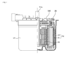
- FIG.1 is a partially cut-out cross-sectional view illustrating a motor according to an exemplary embodiment of the present disclosure
- FIG.2 is a perspective view illustrating a busbar according to an exemplary embodiment of the present disclosure
- FIGS. 3 to 5 are schematic views view illustrating a shape of a busbar terminal according to first, second and third exemplary embodiments of the present disclosure
- FIG.6 is a schematic view illustrating a state in which a busbar terminal is formed by press-work of a plate
- FIG.7 is a schematic view illustrating a one-polarity busbar terminal formed by circularly bending a busbar terminal of FIG.6
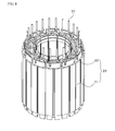
- FIG.8 is a perspective view illustrating a stator core wound with a coil
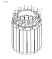
- FIG. 9 is a perspective view illustrating a state in which a distal end of a coil wound on the stator core of FIG.8 is stripped, and inserted with a busbar according to an exemplary embodiment of the present disclosure
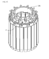
- FIG. 10 is a perspective view illustrating a state in which a portion of a stripped coil protruded to an upper surface of the busbar of FIG.9 is cut out according to the exemplary embodiment of the present disclosure
- FIG.11 is a perspective view illustrating a state in which the stripped portion of the coil in FIG. 10 is bent and hooked to a busbar terminal
- FIG.12 a perspective view illustrating a state in which an upper surface of a plate module of FIG.9 is soldered by a conductive member.
- an EPS motor includes a motor housing (10), a stator (20), and a rotor (30), and may further include a busbar (100) for supplying an electric power to a coil (22) wound on the stator (20).
- the motor housing (10) takes an approximate shape of a cylinder, and is formed with at an upper surface with an opening and closed at a bottom surface.
- the motor housing (10) is installed therein with the stator (20), the rotor (30) and a rotation shaft (30a) rotatably supporting the rotor (30).
- the stator (20) includes a stator core (21), a coil (22) and a coil terminal (25) formed by stripping a distal end of the coil.
- the stator core (21) may be provided with a plurality of teeth, and the teeth may be circumferentially wound with the coil (22) while the teeth are mounted with an insulator.
- the distal end of the coil (22) is stripped to form the coil terminal (25), where the coil terminal (25) may be provided in a cylindrical shape having a predetermined length and a predetermined diameter.
- the stator (20) may be assembled at an upper surface with the busbar (100) for supplying an electrical power to the coil (22).
- the busbar (100) may be formed with a plurality of busbar terminals (110) protruded toward a periphery of the body formed with a resin material as shown in FIG.2 .
- Characteristic of the present disclosure lies in a shape and a structure of the busbar (110), which will be described later.
- the rotor (30) is rotatably mounted at a center of the stator (20), and is formed by a plurality of magnets being mounted at a periphery of rotor core.
- the rotation shaft (30a) is coaxially formed with the rotor (30), where one end of the rotation shaft (30a) is rotatably supported by a bottom bearing mounted at a floor surface of the motor housing (10), and the other end of the rotation shaft (30a) is supported by an upper bearing installed on a cover member (not shown).
- Each of the busbars (100) functions to supply an electric power to the coil (22) wound on the stator core (21), and may include a ring-shaped body (101) having a diameter corresponding to the stator (20), and a plurality of busbar terminals (110) arranged along the periphery of the body (101) each spaced apart at a predetermined gap to supply an electric power having mutually different polarities to the coil (22).
- the busbar terminal (110) may be provided with a conductive material and may be generally formed with a metal material easy for press work.
- the busbar terminal (110) may be formed with a groove-less square plate member as shown in FIG.3 .
- the coil (22) may be bent and wound toward an upper side of the busbar terminal (110) and connected by being fused with a contact portion of the coil terminal (25) formed at a distal end of the coil (22).
- the busbar terminal (110) may be formed with a hook groove (111) having a shape corresponding to the coil (22) as illustrated in FIG.4 , where the coil terminal (25) formed at the distal end of the coil (22) may be accommodated into the hook groove (111), and the busbar terminal (110) may be connected by fusing a contact portion between an inner surface of the hook groove (111) the coil terminal (25).
- the busbar terminal (110) may be provided with a through hole (121) having a shape corresponding to that of the periphery of the coil as illustrated in FIG.5 , and with a slit (122) forming a hitching unit having a width of a value smaller than a diameter of the through hole (121).
- the coil terminal (25) formed at a distal end of the coil may be pushed in through the slit (122) for accommodation into the through hole (121), and the coil terminal (25) may be conductively connected to the busbar terminal (110) by fusing the slit portion.
- the busbar terminal (110) may be configured such that the busbar terminal (110) and a terminal body (112) are formed on one sheet of plate member (P) to remove a space (S) and fold in a circular manner as shown in FIG. 7 .
- a quantity of scraps cut to the space (S) can be minimized to reduce material that is to be wasted, and folded at the terminal body (112) twice to form the busbar terminal (110), whereby process can be simplified.
- the busbar terminal (110) thus configured may be protrusively formed on the ring-shaped body (101) so as to have a first height and a second height. This is to minimize interference between coils (22) hooked on adjacent busbar terminals (110).
- the present disclosure relates to a brushless motor using a 3-phase (U, V, W) electric power, and a general structure of the stator (20) is the same as that explained in FIG. 1 .
- a distal end (23) of the coil (22) wound on the stator core (21) may be arranged in a state of being lengthily stood at an upper surface of the stator core while being wrapped in an insulated coating wrapping the coil (22).
- the distal end (23) of the coil may be arranged at an erect state to a direction parallel with a lengthwise direction of the stator core (21), and the distal end (23) of the coil may be arranged near to the busbar terminal (110) protrusively formed to a periphery of the busbar (100).
- the busbar (100) is installed as shown in FIG.9 , while a coating-stripped distal end (23) of the coil (22) is erected, a strip portion (24) protruded to an upper surface of the busbar (100) is removed as shown in FIG. 10 to form the coil terminal (25) with an appropriate length, and a portion of the coil terminal (25) may be formed at a position near to the busbar terminal (110) as illustrated in FIG. 10 .
- the coil terminal (25) is bent in a U shape to be accommodated into the hook groove (111) formed on the busbar terminal (110).
- the coil terminal (25) accommodated into the hook groove (111) may be soldered using a conductive material such as a lead, whereby assembly can be finished.
- the motor according to exemplary embodiments of the present disclosure has an advantageous effect in that a busbar (100) excellent in connectivity with the coil (22) over the conventional busbar can be manufactured, and particularly, the amount of scraps generated in the course of manufacturing the busbar terminal (110) can be minimized.
- the coil terminal (25) can be arranged at an accurate position to reduce defects during manufacturing such as the coil terminal (25) being disengaged from or erroneously connected with the busbar terminal (110) during fusing process.
Landscapes
- Engineering & Computer Science (AREA)
- Power Engineering (AREA)
- Insulation, Fastening Of Motor, Generator Windings (AREA)
- Motor Or Generator Frames (AREA)
Abstract
Description
- The present disclosure relates to a brushless motor.
- Generally, almost every vehicle employs an electric power-assist steering system. Such an electric power-assist steering system generates an assist force based on the steering torque and the steering angle in order to enhance the steering performance of the vehicle.
- That is, a steering system that assists a steering force of a vehicle with a separate power is used to enhance the motion stability of a vehicle.
- Conventionally, the auxiliary steering device uses hydraulic pressure, but an Electronic Power Steering (EPS) system adapted to transmit a rotation output of an electric motor to a steering shaft via a speed reduction mechanism has been increasingly employed these days from a viewpoint of a reduction in engine load, a reduction in weight, an enhanced steering stability and a quick restoring force.
- The EPS system is configured such that an Electronic Control Unit (ECU) drives a motor in response to steering conditions detected by a speed sensor, a torque angle sensor and a torque sensor to enhance a steering stability and provide a quick restoring force, whereby a driver can safely steer a vehicle.
- The EPS system is also such that a motor assists a torque manipulating a steering wheel to allow a driver to steer a vehicle with less power, where the motor employs a Brushless Direct Current (BLDC) motor.
- The BLDC motors have been increasingly used because the brushless motors are excellent in maintenance property, have a small size, and are capable of generating a high torque.
- The BLDC motor generally forms an exterior look by coupling of a housing with a cover member, an inner circumferential surface of the housing is provided with a stator, and the stator is centrally formed with a rotor rotatably mounted in electrical interaction with the stator. The rotor is rotatably supported by a rotation shaft, and an upper surface of the rotation shaft is connected by a steering shaft of a vehicle to provide a power assisting the steering of the vehicle as mentioned above. The stator of EPS motor thus configured serves to supply an electric power to a wound coil via busbar.
- The stator includes a core and a coil wound on the core, and in general, a motor used for a vehicle is employed with a plurality of coils connected in parallel for loss reduction. Thus, the coil is extended to an input/output terminal, and integrated and connected at the terminal during parallel connection. In order to integrate and connect the coil arranged in parallel, a busbar is coupled to an upper surface of the stator, and in order to couple the busbar, a coil terminal of coils respectively wound on the upper surface of stator, and the busbar is connected to the coil terminal.
- The busbar is fixedly arranged with a plurality of metal members electrically connected to the coil terminal which is then insulated by an insulator. The busbar takes an approximate shape of a doughnut to correspond to a shape of the stator. The busbar is arranged at a periphery with terminals for connecting the coil terminal.
- The shape of a busbar is change in response to a connected electrical power, and in general, the EPS motor is configured such that respective input/output terminals are sequentially arranged to a periphery of the busbar through a 3-phase circuit.
- However, there is a disadvantage in forming the busbar terminal bent to the busbar in that each busbar terminal must be bent at a predetermined size, and it is too much complicated to insert and fuse the coil into the busbar terminal, frequently generating faulty works.
- Particularly, molds are complicated, and materials are wasted because of complicated shape of a fusing unit and generation of too much of scraps when the busbar terminal is manufactured using a press forming method, in a case the busbar terminal and the coil are fixed by being fused, and fusing unit is formed in a U-shape.
- Another disadvantage is that a large quantity of straight portions of a coil for pulling the coil is required to resultantly waste a large quantity of coils, because the U-shaped ring type busbar terminal must be penetrated through a U-shaped ring, pulled, fused and cut.
- The present disclosure is directed to cope with the abovementioned problems/disadvantages and it is an object of the present disclosure to provide a structure-improved brushless motor configured to improve motor assembly.
- 1. In one general aspect of the present disclosure, there is provided a motor, the motor comprising:
- a motor housing;
- a stator mounted inside the motor housing and including a stator core and a coil wound on the stator core;
- a rotor rotatably installed at a center of the stator; and
- a busbar provided with a plurality of circumferentially and straightly protruded busbar terminals mounted at an upper surface of the stator, and connected by a coil.
- 2. Preferably, but not necessarily, the busbar may include a resin materialed busbar body, and a busbar terminal protruded to a circumferential direction of the busbar body.
- 3. Preferably, but not necessarily, a cross-section of the busbar terminal may take a shape of a rectangle.
- 4. Preferably, but not necessarily, the busbar terminal may be a hook groove having a width corresponding to a diameter of the coil.
- 5. Preferably, but not necessarily, the busbar terminal may include a through hole having a shape corresponding to that of a periphery of the coil, and a slit having a hitching unit having a width smaller value than that of a diameter of the through hole.
- 6. Preferably, but not necessarily, the slit may be formed with a bottleneck section formed by a width of a connection unit connected to the through hole smaller than a width of an opening connected to an outside of the busbar terminal.
- 7. Preferably, but not necessarily, the body may be formed with a resin material to be insert injection molded along with the busbar terminal.
- 8. Preferably, but not necessarily, the busbar terminal may be formed in one body with a circularly bent terminal body having a diameter corresponding to the body after press-work of a plate member, and the busbar terminal may be at least twice bent on the terminal body to allow a distal end to a circumferential direction of the body.
- 9. Preferably, but not necessarily, the busbar terminal may include a fusing unit formed with a conductive member at an area contacting the coil.
- 10. Preferably, but not necessarily, the busbar terminal may be arranged at a first height and at a second height at a periphery of the busbar terminal.
- There is an advantageous effect in the motor according to an exemplary embodiment of the present disclosure in that a hook groove is formed at a busbar terminal to allow a coil to be directly hooked and coupled to a busbar terminal by bending the coil, whereby a manufacturing cost can be reduced by decreasing an amount of scraps generated in the course of manufacturing a busbar terminal, and a motor assembly can be improved by completion of connection process in which a stripper at a distal end of the coil is bent and fused by being coupled to a hook groove.
-
-
FIG.1 is a partially cut-out cross-sectional view illustrating a motor according to an - exemplary embodiment of the present disclosure.
-
FIG.2 is a perspective view illustrating a busbar according to an exemplary - embodiment of the present disclosure.
-
FIGS. 3 to 5 are schematic views view illustrating a shape of a busbar terminal according to first, second and third exemplary embodiments of the present disclosure. -
FIG.6 is a schematic view illustrating a state in which a busbar terminal is formed by press-work of a plate. -
FIG.7 is a schematic view illustrating a one-polarity busbar terminal formed by circularly bending a busbar terminal ofFIG.6 . -
FIG.8 is a perspective view illustrating a stator core wound with a coil. -
FIG. 9 is a perspective view illustrating a state in which a distal end of a coil wound on the stator core ofFIG.8 is stripped, and inserted with a busbar according to an exemplary embodiment of the present disclosure. -
FIG. 10 is a perspective view illustrating a state in which a portion of a stripped coil protruded to an upper surface of the busbar ofFIG.9 is cut out according to the exemplary embodiment of the present disclosure. -
FIG.11 is a perspective view illustrating a state in which the stripped portion of the coil inFIG. 10 is bent and hooked to a busbar terminal. -
FIG.12 a perspective view illustrating a state in which an upper surface of a plate module ofFIG.9 is soldered by a conductive member. - Now, a motor according to the exemplary embodiment of the present disclosure will be described in detail with reference to the accompanying drawings.
-
FIG.1 is a partially cut-out cross-sectional view illustrating a motor according to an exemplary embodiment of the present disclosure,FIG.2 is a perspective view illustrating a busbar according to an exemplary embodiment of the present disclosure,FIGS. 3 to 5 are schematic views view illustrating a shape of a busbar terminal according to first, second and third exemplary embodiments of the present disclosure,FIG.6 is a schematic view illustrating a state in which a busbar terminal is formed by press-work of a plate,FIG.7 is a schematic view illustrating a one-polarity busbar terminal formed by circularly bending a busbar terminal ofFIG.6 ,FIG.8 is a perspective view illustrating a stator core wound with a coil,FIG. 9 is a perspective view illustrating a state in which a distal end of a coil wound on the stator core ofFIG.8 is stripped, and inserted with a busbar according to an exemplary embodiment of the present disclosure,FIG. 10 is a perspective view illustrating a state in which a portion of a stripped coil protruded to an upper surface of the busbar ofFIG.9 is cut out according to the exemplary embodiment of the present disclosure,FIG.11 is a perspective view illustrating a state in which the stripped portion of the coil inFIG. 10 is bent and hooked to a busbar terminal andFIG.12 a perspective view illustrating a state in which an upper surface of a plate module ofFIG.9 is soldered by a conductive member. - Referring to
FIG.1 , an EPS motor according to an exemplary embodiment of the present disclosure includes a motor housing (10), a stator (20), and a rotor (30), and may further include a busbar (100) for supplying an electric power to a coil (22) wound on the stator (20). - The motor housing (10) takes an approximate shape of a cylinder, and is formed with at an upper surface with an opening and closed at a bottom surface. The motor housing (10) is installed therein with the stator (20), the rotor (30) and a rotation shaft (30a) rotatably supporting the rotor (30). The stator (20) includes a stator core (21), a coil (22) and a coil terminal (25) formed by stripping a distal end of the coil. The stator core (21) may be provided with a plurality of teeth, and the teeth may be circumferentially wound with the coil (22) while the teeth are mounted with an insulator. The distal end of the coil (22) is stripped to form the coil terminal (25), where the coil terminal (25) may be provided in a cylindrical shape having a predetermined length and a predetermined diameter.
- The stator (20) may be assembled at an upper surface with the busbar (100) for supplying an electrical power to the coil (22). The busbar (100) may be formed with a plurality of busbar terminals (110) protruded toward a periphery of the body formed with a resin material as shown in
FIG.2 . Characteristic of the present disclosure lies in a shape and a structure of the busbar (110), which will be described later. - The rotor (30) is rotatably mounted at a center of the stator (20), and is formed by a plurality of magnets being mounted at a periphery of rotor core. The rotation shaft (30a) is coaxially formed with the rotor (30), where one end of the rotation shaft (30a) is rotatably supported by a bottom bearing mounted at a floor surface of the motor housing (10), and the other end of the rotation shaft (30a) is supported by an upper bearing installed on a cover member (not shown).
- Each of the busbars (100) according to an exemplary embodiment of the present disclosure functions to supply an electric power to the coil (22) wound on the stator core (21), and may include a ring-shaped body (101) having a diameter corresponding to the stator (20), and a plurality of busbar terminals (110) arranged along the periphery of the body (101) each spaced apart at a predetermined gap to supply an electric power having mutually different polarities to the coil (22). The busbar terminal (110) may be provided with a conductive material and may be generally formed with a metal material easy for press work.
- According to a first exemplary embodiment of the present disclosure, the busbar terminal (110) may be formed with a groove-less square plate member as shown in
FIG.3 . In this case, the coil (22) may be bent and wound toward an upper side of the busbar terminal (110) and connected by being fused with a contact portion of the coil terminal (25) formed at a distal end of the coil (22). - According to a second exemplary embodiment of the present disclosure, the busbar terminal (110) may be formed with a hook groove (111) having a shape corresponding to the coil (22) as illustrated in
FIG.4 , where the coil terminal (25) formed at the distal end of the coil (22) may be accommodated into the hook groove (111), and the busbar terminal (110) may be connected by fusing a contact portion between an inner surface of the hook groove (111) the coil terminal (25). - According to a third exemplary embodiment of the present disclosure, the busbar terminal (110) may be provided with a through hole (121) having a shape corresponding to that of the periphery of the coil as illustrated in
FIG.5 , and with a slit (122) forming a hitching unit having a width of a value smaller than a diameter of the through hole (121). In this case, the coil terminal (25) formed at a distal end of the coil may be pushed in through the slit (122) for accommodation into the through hole (121), and the coil terminal (25) may be conductively connected to the busbar terminal (110) by fusing the slit portion. - Referring to
FIG.6 , the busbar terminal (110) may be configured such that the busbar terminal (110) and a terminal body (112) are formed on one sheet of plate member (P) to remove a space (S) and fold in a circular manner as shown inFIG. 7 . - According to the abovementioned configuration, a quantity of scraps cut to the space (S) can be minimized to reduce material that is to be wasted, and folded at the terminal body (112) twice to form the busbar terminal (110), whereby process can be simplified.
- Furthermore, as illustrated in
FIG.2 , the busbar terminal (110) thus configured may be protrusively formed on the ring-shaped body (101) so as to have a first height and a second height. This is to minimize interference between coils (22) hooked on adjacent busbar terminals (110). - Now, a coupling method of the busbar (100) according to the present disclosure will be described with reference to
FIGS. 8 to 12 . The present disclosure relates to a brushless motor using a 3-phase (U, V, W) electric power, and a general structure of the stator (20) is the same as that explained inFIG. 1 . - Referring to
FIG.8 , a distal end (23) of the coil (22) wound on the stator core (21) may be arranged in a state of being lengthily stood at an upper surface of the stator core while being wrapped in an insulated coating wrapping the coil (22). At this time, the distal end (23) of the coil may be arranged at an erect state to a direction parallel with a lengthwise direction of the stator core (21), and the distal end (23) of the coil may be arranged near to the busbar terminal (110) protrusively formed to a periphery of the busbar (100). - Referring to
FIG.8 , the busbar (100) is installed as shown inFIG.9 , while a coating-stripped distal end (23) of the coil (22) is erected, a strip portion (24) protruded to an upper surface of the busbar (100) is removed as shown inFIG. 10 to form the coil terminal (25) with an appropriate length, and a portion of the coil terminal (25) may be formed at a position near to the busbar terminal (110) as illustrated inFIG. 10 . - Furthermore, as illustrated in
FIG. 11 , the coil terminal (25) is bent in a U shape to be accommodated into the hook groove (111) formed on the busbar terminal (110). The coil terminal (25) accommodated into the hook groove (111) may be soldered using a conductive material such as a lead, whereby assembly can be finished. - As apparent from the foregoing, the motor according to exemplary embodiments of the present disclosure has an advantageous effect in that a busbar (100) excellent in connectivity with the coil (22) over the conventional busbar can be manufactured, and particularly, the amount of scraps generated in the course of manufacturing the busbar terminal (110) can be minimized.
- Another advantageous effect is that, in a case the hook groove (111) is formed at the busbar terminal (110), the coil terminal (25) can be arranged at an accurate position to reduce defects during manufacturing such as the coil terminal (25) being disengaged from or erroneously connected with the busbar terminal (110) during fusing process.
- Although embodiments have been described with reference to a number of illustrative embodiments thereof, it should be understood that numerous other modifications and embodiments can be devised by those skilled in the art that will fall within the spirit and scope of the principles of this disclosure. More particularly, various variations and modifications are possible in the component parts and/or arrangements of the subject combination arrangement within the scope of the disclosure, the drawings and the appended claims.
Claims (10)
- A motor including a motor housing (10), a stator (20) mounted inside the motor housing (10) and including a stator core (21) and a coil (22) wound on the stator core (21), and a rotor (30) rotatably installed at a center of the stator (20), the motor characterized by a busbar (100) mounted at an upper surface of the stator (20), connected by a coil (22) and provided with a plurality of circumferentially and straightly protruded busbar terminals (110).
- The motor of claim 1, characterized in that the busbar (100) includes a resin materialed busbar body (101), and a busbar terminal (110) protruded to a circumferential direction of the busbar body (101).
- The motor of claim 2, characterized in that a cross-section of the busbar terminal (110) takes a shape of a rectangle.
- The motor of claim 3, characterized in that the busbar terminal (110) is a hook groove (111) having a width corresponding to a diameter of the coil (22).
- The motor of claim 3, characterized in that the busbar terminal (110) includes a through hole (121) having a shape corresponding to that of a periphery of the coil (22), and a slit (122) having a hitching unit having a width smaller value than that of a diameter of the through hole.
- The motor of claim 5, characterized in that the slit is formed with a bottleneck section formed by a width of a connection unit connected to the through hole (121) smaller than a width of an opening connected to an outside of the busbar terminal (110).
- The motor of claim 2, characterized in that the body is formed with a resin material to be insert injection molded along with the busbar terminal.
- The motor of claim 2, characterized in that the busbar terminal (110) is formed in one body with a circularly bent terminal body having a diameter corresponding to the body after press-work of a plate member, and the busbar terminal is at least twice bent on the terminal body to allow a distal end to a circumferential direction of the body.
- The motor of claim 2, characterized in that the busbar terminal (110) includes a fusing unit formed with a conductive member at an area contacting the coil.
- The motor of claim 2, characterized in that the busbar terminal (110) is arranged at a first height and at a second height at a periphery of the busbar terminal.
Applications Claiming Priority (1)
| Application Number | Priority Date | Filing Date | Title |
|---|---|---|---|
| KR1020120069846A KR101992687B1 (en) | 2012-06-28 | 2012-06-28 | Motor |
Publications (3)
| Publication Number | Publication Date |
|---|---|
| EP2680406A2 true EP2680406A2 (en) | 2014-01-01 |
| EP2680406A3 EP2680406A3 (en) | 2017-05-31 |
| EP2680406B1 EP2680406B1 (en) | 2020-01-15 |
Family
ID=48698923
Family Applications (1)
| Application Number | Title | Priority Date | Filing Date |
|---|---|---|---|
| EP13173468.3A Active EP2680406B1 (en) | 2012-06-28 | 2013-06-24 | Motor |
Country Status (5)
| Country | Link |
|---|---|
| US (1) | US9312737B2 (en) |
| EP (1) | EP2680406B1 (en) |
| JP (1) | JP6228759B2 (en) |
| KR (1) | KR101992687B1 (en) |
| CN (1) | CN103532312B (en) |
Cited By (1)
| Publication number | Priority date | Publication date | Assignee | Title |
|---|---|---|---|---|
| CN114365398A (en) * | 2019-09-10 | 2022-04-15 | 美蓓亚三美株式会社 | Stator structure of motor, and moving body |
Families Citing this family (22)
| Publication number | Priority date | Publication date | Assignee | Title |
|---|---|---|---|---|
| DE112013006985T5 (en) * | 2013-04-26 | 2016-01-14 | Mitsubishi Electric Corporation | Electric circulating machine |
| KR101604914B1 (en) | 2014-08-04 | 2016-03-21 | 뉴모텍(주) | Motor with Bus-bar Assembly |
| KR101604915B1 (en) * | 2014-08-04 | 2016-03-21 | 뉴모텍(주) | Motor with Bus-bar Assembly |
| DE102014221188A1 (en) * | 2014-10-20 | 2016-04-21 | Bayerische Motoren Werke Aktiengesellschaft | Switching ring arrangement for an electrical machine |
| KR101940682B1 (en) * | 2015-04-07 | 2019-01-22 | 엘지이노텍 주식회사 | Stator and motor using the same |
| KR102374858B1 (en) * | 2015-07-21 | 2022-03-17 | 엘지이노텍 주식회사 | Terminal assembly and Motor having the same |
| US10374480B2 (en) * | 2015-08-10 | 2019-08-06 | Nidec Corporation | Motor |
| KR102529820B1 (en) * | 2015-11-03 | 2023-05-08 | 엘지이노텍 주식회사 | Motor |
| KR102625432B1 (en) * | 2016-01-08 | 2024-01-16 | 엘지이노텍 주식회사 | Busbar terminal, busbar, motor and vehicle having the same |
| KR102701654B1 (en) * | 2016-06-09 | 2024-09-03 | 엘지이노텍 주식회사 | Ground terminal, Cover assembly and vehicle having the same |
| US10618423B2 (en) * | 2017-09-15 | 2020-04-14 | Ford Global Technologies, Llc | Isolated dual bus hybrid vehicle drivetrain |
| CN111247723B (en) * | 2017-10-27 | 2022-09-06 | 日本电产株式会社 | Motor and method for manufacturing motor |
| CN111373636A (en) * | 2017-11-24 | 2020-07-03 | 日本电产株式会社 | motor |
| DE102018217857B4 (en) * | 2018-10-18 | 2022-02-03 | Bühler Motor GmbH | DC motor and method for its manufacture |
| CN111628593B (en) * | 2019-02-28 | 2023-04-07 | 株式会社村田制作所 | Stator, stator assembly, converter of electric energy and mechanical energy |
| WO2021125562A1 (en) * | 2019-12-17 | 2021-06-24 | 엘지이노텍 주식회사 | Motor |
| JP7018081B2 (en) | 2020-02-13 | 2022-02-09 | シナノケンシ株式会社 | Electric pump |
| KR102832207B1 (en) * | 2020-07-21 | 2025-07-10 | 현대모비스 주식회사 | Bus bar unit for motor |
| KR20220103391A (en) * | 2021-01-15 | 2022-07-22 | 엘지이노텍 주식회사 | Motor |
| KR20220127558A (en) * | 2021-03-11 | 2022-09-20 | 엘지이노텍 주식회사 | motor |
| CN115714500A (en) * | 2021-08-23 | 2023-02-24 | 安徽威灵汽车部件有限公司 | Busbar prefabricated part, busbar, motor and vehicle |
| CN114597722B (en) * | 2021-12-17 | 2023-08-11 | 杭州多宝电子股份有限公司 | Annular busbar assembly |
Family Cites Families (17)
| Publication number | Priority date | Publication date | Assignee | Title |
|---|---|---|---|---|
| CN1122528A (en) * | 1994-10-31 | 1996-05-15 | 三和化学株式会社 | Molded motor |
| JPH11299159A (en) * | 1998-04-10 | 1999-10-29 | Honda Motor Co Ltd | Connecting ring for motor stator and method of manufacturing the same |
| DE19920127C2 (en) | 1999-05-03 | 2001-05-31 | Mannesmann Sachs Ag | Stator for an electrical machine and method for producing a stator |
| JP3696080B2 (en) * | 2000-12-05 | 2005-09-14 | 三菱電機株式会社 | Rotating electric machine |
| JP3613262B2 (en) * | 2002-04-26 | 2005-01-26 | 三菱電機株式会社 | Rotating electric machine and manufacturing method thereof |
| CN100411279C (en) * | 2002-07-22 | 2008-08-13 | 日本精工株式会社 | 3-phase permanent magnet motor |
| DE502005000329D1 (en) * | 2005-03-17 | 2007-03-08 | Zahnradfabrik Friedrichshafen | Stator for an electric machine |
| JP2007318885A (en) * | 2006-05-25 | 2007-12-06 | Mabuchi Motor Co Ltd | Brushless motor |
| JP2008079465A (en) * | 2006-09-22 | 2008-04-03 | Mitsuba Corp | Brushless motor |
| JP2008278704A (en) * | 2007-05-02 | 2008-11-13 | Sumitomo Electric Ind Ltd | Stator for rotating electrical machine, connection structure between coil terminal and bus bar terminal, and connection method thereof |
| JP4902438B2 (en) * | 2007-06-22 | 2012-03-21 | 日信工業株式会社 | Electric motor |
| JP5335265B2 (en) * | 2008-03-28 | 2013-11-06 | 三洋電機株式会社 | Electric motor |
| JP2009290921A (en) * | 2008-05-27 | 2009-12-10 | Mitsuba Corp | Brushless motor |
| JP4688910B2 (en) * | 2008-08-08 | 2011-05-25 | 三菱電機株式会社 | Electric power steering motor |
| JP2010200400A (en) * | 2009-02-23 | 2010-09-09 | Nippon Densan Corp | Stator, bus bar unit, motor, and power steering device |
| EP2458715B1 (en) * | 2010-11-05 | 2014-01-08 | LG Innotek Co., Ltd. | Bus bar of EPS motor |
| JP2012110188A (en) * | 2010-11-19 | 2012-06-07 | Nippon Densan Corp | Intermediate connection member, stator, and motor |
-
2012
- 2012-06-28 KR KR1020120069846A patent/KR101992687B1/en not_active Expired - Fee Related
-
2013
- 2013-06-24 EP EP13173468.3A patent/EP2680406B1/en active Active
- 2013-06-26 JP JP2013133629A patent/JP6228759B2/en active Active
- 2013-06-28 US US13/930,462 patent/US9312737B2/en active Active
- 2013-06-28 CN CN201310265576.6A patent/CN103532312B/en active Active
Non-Patent Citations (1)
| Title |
|---|
| None |
Cited By (1)
| Publication number | Priority date | Publication date | Assignee | Title |
|---|---|---|---|---|
| CN114365398A (en) * | 2019-09-10 | 2022-04-15 | 美蓓亚三美株式会社 | Stator structure of motor, and moving body |
Also Published As
| Publication number | Publication date |
|---|---|
| US9312737B2 (en) | 2016-04-12 |
| CN103532312A (en) | 2014-01-22 |
| US20140001896A1 (en) | 2014-01-02 |
| CN103532312B (en) | 2017-12-19 |
| EP2680406A3 (en) | 2017-05-31 |
| EP2680406B1 (en) | 2020-01-15 |
| KR20140003779A (en) | 2014-01-10 |
| JP2014011954A (en) | 2014-01-20 |
| KR101992687B1 (en) | 2019-06-25 |
| JP6228759B2 (en) | 2017-11-08 |
Similar Documents
| Publication | Publication Date | Title |
|---|---|---|
| US9312737B2 (en) | Motor | |
| US9973052B2 (en) | Stator of motor having insulation structure for separation of stator winding groups | |
| CN107623396B (en) | Busbar of electric power steering motor | |
| US9079603B2 (en) | Motor for an electric power steering apparatus | |
| EP2680405A2 (en) | Motor | |
| CN105471152A (en) | Drive apparatus | |
| KR20160123143A (en) | Terminal asembly for motor and Motor using the same | |
| EP1947754B1 (en) | Busbar structure, method of producing the busbar structure, and electric motor having the busbar structure | |
| KR20130061283A (en) | Stator of eps motor | |
| CN107660322A (en) | Control device | |
| JP2007174869A (en) | Insulator, stator assembly, segment stator, and stator for rotating electrical machine | |
| US10144447B2 (en) | Control unit and electric power steering device using same, and method for manufacturing control unit | |
| KR101829056B1 (en) | Bus-bar of eps motor | |
| US6141864A (en) | Motor stator winding tool | |
| KR20120048319A (en) | Mold structure for bus-bar of eps motor | |
| JP7059739B2 (en) | motor | |
| JP6488100B2 (en) | Electric motor | |
| KR20130019091A (en) | Stator of motor |
Legal Events
| Date | Code | Title | Description |
|---|---|---|---|
| PUAI | Public reference made under article 153(3) epc to a published international application that has entered the european phase |
Free format text: ORIGINAL CODE: 0009012 |
|
| AK | Designated contracting states |
Kind code of ref document: A2 Designated state(s): AL AT BE BG CH CY CZ DE DK EE ES FI FR GB GR HR HU IE IS IT LI LT LU LV MC MK MT NL NO PL PT RO RS SE SI SK SM TR |
|
| AX | Request for extension of the european patent |
Extension state: BA ME |
|
| 17P | Request for examination filed |
Effective date: 20140328 |
|
| RBV | Designated contracting states (corrected) |
Designated state(s): AL AT BE BG CH CY CZ DE DK EE ES FI FR GB GR HR HU IE IS IT LI LT LU LV MC MK MT NL NO PL PT RO RS SE SI SK SM TR |
|
| RAP1 | Party data changed (applicant data changed or rights of an application transferred) |
Owner name: LG INNOTEK CO., LTD. |
|
| PUAL | Search report despatched |
Free format text: ORIGINAL CODE: 0009013 |
|
| RAP1 | Party data changed (applicant data changed or rights of an application transferred) |
Owner name: LG INNOTEK CO., LTD. |
|
| RIC1 | Information provided on ipc code assigned before grant |
Ipc: H02K 5/22 20060101ALN20170419BHEP Ipc: H02K 3/52 20060101AFI20170419BHEP |
|
| AK | Designated contracting states |
Kind code of ref document: A3 Designated state(s): AL AT BE BG CH CY CZ DE DK EE ES FI FR GB GR HR HU IE IS IT LI LT LU LV MC MK MT NL NO PL PT RO RS SE SI SK SM TR |
|
| AX | Request for extension of the european patent |
Extension state: BA ME |
|
| STAA | Information on the status of an ep patent application or granted ep patent |
Free format text: STATUS: EXAMINATION IS IN PROGRESS |
|
| 17Q | First examination report despatched |
Effective date: 20181112 |
|
| GRAP | Despatch of communication of intention to grant a patent |
Free format text: ORIGINAL CODE: EPIDOSNIGR1 |
|
| STAA | Information on the status of an ep patent application or granted ep patent |
Free format text: STATUS: GRANT OF PATENT IS INTENDED |
|
| RIC1 | Information provided on ipc code assigned before grant |
Ipc: H02K 5/22 20060101ALN20190719BHEP Ipc: H02K 3/52 20060101AFI20190719BHEP |
|
| INTG | Intention to grant announced |
Effective date: 20190807 |
|
| GRAS | Grant fee paid |
Free format text: ORIGINAL CODE: EPIDOSNIGR3 |
|
| GRAA | (expected) grant |
Free format text: ORIGINAL CODE: 0009210 |
|
| STAA | Information on the status of an ep patent application or granted ep patent |
Free format text: STATUS: THE PATENT HAS BEEN GRANTED |
|
| AK | Designated contracting states |
Kind code of ref document: B1 Designated state(s): AL AT BE BG CH CY CZ DE DK EE ES FI FR GB GR HR HU IE IS IT LI LT LU LV MC MK MT NL NO PL PT RO RS SE SI SK SM TR |
|
| REG | Reference to a national code |
Ref country code: CH Ref legal event code: EP Ref country code: GB Ref legal event code: FG4D |
|
| REG | Reference to a national code |
Ref country code: IE Ref legal event code: FG4D |
|
| REG | Reference to a national code |
Ref country code: DE Ref legal event code: R096 Ref document number: 602013065059 Country of ref document: DE |
|
| REG | Reference to a national code |
Ref country code: AT Ref legal event code: REF Ref document number: 1226029 Country of ref document: AT Kind code of ref document: T Effective date: 20200215 |
|
| REG | Reference to a national code |
Ref country code: NL Ref legal event code: FP |
|
| REG | Reference to a national code |
Ref country code: LT Ref legal event code: MG4D |
|
| PG25 | Lapsed in a contracting state [announced via postgrant information from national office to epo] |
Ref country code: RS Free format text: LAPSE BECAUSE OF FAILURE TO SUBMIT A TRANSLATION OF THE DESCRIPTION OR TO PAY THE FEE WITHIN THE PRESCRIBED TIME-LIMIT Effective date: 20200115 Ref country code: FI Free format text: LAPSE BECAUSE OF FAILURE TO SUBMIT A TRANSLATION OF THE DESCRIPTION OR TO PAY THE FEE WITHIN THE PRESCRIBED TIME-LIMIT Effective date: 20200115 Ref country code: PT Free format text: LAPSE BECAUSE OF FAILURE TO SUBMIT A TRANSLATION OF THE DESCRIPTION OR TO PAY THE FEE WITHIN THE PRESCRIBED TIME-LIMIT Effective date: 20200607 Ref country code: NO Free format text: LAPSE BECAUSE OF FAILURE TO SUBMIT A TRANSLATION OF THE DESCRIPTION OR TO PAY THE FEE WITHIN THE PRESCRIBED TIME-LIMIT Effective date: 20200415 |
|
| PG25 | Lapsed in a contracting state [announced via postgrant information from national office to epo] |
Ref country code: SE Free format text: LAPSE BECAUSE OF FAILURE TO SUBMIT A TRANSLATION OF THE DESCRIPTION OR TO PAY THE FEE WITHIN THE PRESCRIBED TIME-LIMIT Effective date: 20200115 Ref country code: LV Free format text: LAPSE BECAUSE OF FAILURE TO SUBMIT A TRANSLATION OF THE DESCRIPTION OR TO PAY THE FEE WITHIN THE PRESCRIBED TIME-LIMIT Effective date: 20200115 Ref country code: BG Free format text: LAPSE BECAUSE OF FAILURE TO SUBMIT A TRANSLATION OF THE DESCRIPTION OR TO PAY THE FEE WITHIN THE PRESCRIBED TIME-LIMIT Effective date: 20200415 Ref country code: GR Free format text: LAPSE BECAUSE OF FAILURE TO SUBMIT A TRANSLATION OF THE DESCRIPTION OR TO PAY THE FEE WITHIN THE PRESCRIBED TIME-LIMIT Effective date: 20200416 Ref country code: IS Free format text: LAPSE BECAUSE OF FAILURE TO SUBMIT A TRANSLATION OF THE DESCRIPTION OR TO PAY THE FEE WITHIN THE PRESCRIBED TIME-LIMIT Effective date: 20200515 Ref country code: HR Free format text: LAPSE BECAUSE OF FAILURE TO SUBMIT A TRANSLATION OF THE DESCRIPTION OR TO PAY THE FEE WITHIN THE PRESCRIBED TIME-LIMIT Effective date: 20200115 |
|
| REG | Reference to a national code |
Ref country code: DE Ref legal event code: R097 Ref document number: 602013065059 Country of ref document: DE |
|
| PG25 | Lapsed in a contracting state [announced via postgrant information from national office to epo] |
Ref country code: SM Free format text: LAPSE BECAUSE OF FAILURE TO SUBMIT A TRANSLATION OF THE DESCRIPTION OR TO PAY THE FEE WITHIN THE PRESCRIBED TIME-LIMIT Effective date: 20200115 Ref country code: EE Free format text: LAPSE BECAUSE OF FAILURE TO SUBMIT A TRANSLATION OF THE DESCRIPTION OR TO PAY THE FEE WITHIN THE PRESCRIBED TIME-LIMIT Effective date: 20200115 Ref country code: DK Free format text: LAPSE BECAUSE OF FAILURE TO SUBMIT A TRANSLATION OF THE DESCRIPTION OR TO PAY THE FEE WITHIN THE PRESCRIBED TIME-LIMIT Effective date: 20200115 Ref country code: SK Free format text: LAPSE BECAUSE OF FAILURE TO SUBMIT A TRANSLATION OF THE DESCRIPTION OR TO PAY THE FEE WITHIN THE PRESCRIBED TIME-LIMIT Effective date: 20200115 Ref country code: RO Free format text: LAPSE BECAUSE OF FAILURE TO SUBMIT A TRANSLATION OF THE DESCRIPTION OR TO PAY THE FEE WITHIN THE PRESCRIBED TIME-LIMIT Effective date: 20200115 Ref country code: ES Free format text: LAPSE BECAUSE OF FAILURE TO SUBMIT A TRANSLATION OF THE DESCRIPTION OR TO PAY THE FEE WITHIN THE PRESCRIBED TIME-LIMIT Effective date: 20200115 Ref country code: LT Free format text: LAPSE BECAUSE OF FAILURE TO SUBMIT A TRANSLATION OF THE DESCRIPTION OR TO PAY THE FEE WITHIN THE PRESCRIBED TIME-LIMIT Effective date: 20200115 Ref country code: CZ Free format text: LAPSE BECAUSE OF FAILURE TO SUBMIT A TRANSLATION OF THE DESCRIPTION OR TO PAY THE FEE WITHIN THE PRESCRIBED TIME-LIMIT Effective date: 20200115 |
|
| REG | Reference to a national code |
Ref country code: AT Ref legal event code: MK05 Ref document number: 1226029 Country of ref document: AT Kind code of ref document: T Effective date: 20200115 |
|
| PLBE | No opposition filed within time limit |
Free format text: ORIGINAL CODE: 0009261 |
|
| STAA | Information on the status of an ep patent application or granted ep patent |
Free format text: STATUS: NO OPPOSITION FILED WITHIN TIME LIMIT |
|
| 26N | No opposition filed |
Effective date: 20201016 |
|
| PG25 | Lapsed in a contracting state [announced via postgrant information from national office to epo] |
Ref country code: MC Free format text: LAPSE BECAUSE OF FAILURE TO SUBMIT A TRANSLATION OF THE DESCRIPTION OR TO PAY THE FEE WITHIN THE PRESCRIBED TIME-LIMIT Effective date: 20200115 Ref country code: AT Free format text: LAPSE BECAUSE OF FAILURE TO SUBMIT A TRANSLATION OF THE DESCRIPTION OR TO PAY THE FEE WITHIN THE PRESCRIBED TIME-LIMIT Effective date: 20200115 Ref country code: IT Free format text: LAPSE BECAUSE OF FAILURE TO SUBMIT A TRANSLATION OF THE DESCRIPTION OR TO PAY THE FEE WITHIN THE PRESCRIBED TIME-LIMIT Effective date: 20200115 |
|
| REG | Reference to a national code |
Ref country code: CH Ref legal event code: PL |
|
| PG25 | Lapsed in a contracting state [announced via postgrant information from national office to epo] |
Ref country code: SI Free format text: LAPSE BECAUSE OF FAILURE TO SUBMIT A TRANSLATION OF THE DESCRIPTION OR TO PAY THE FEE WITHIN THE PRESCRIBED TIME-LIMIT Effective date: 20200115 Ref country code: PL Free format text: LAPSE BECAUSE OF FAILURE TO SUBMIT A TRANSLATION OF THE DESCRIPTION OR TO PAY THE FEE WITHIN THE PRESCRIBED TIME-LIMIT Effective date: 20200115 |
|
| PG25 | Lapsed in a contracting state [announced via postgrant information from national office to epo] |
Ref country code: LU Free format text: LAPSE BECAUSE OF NON-PAYMENT OF DUE FEES Effective date: 20200624 |
|
| REG | Reference to a national code |
Ref country code: BE Ref legal event code: MM Effective date: 20200630 |
|
| PG25 | Lapsed in a contracting state [announced via postgrant information from national office to epo] |
Ref country code: IE Free format text: LAPSE BECAUSE OF NON-PAYMENT OF DUE FEES Effective date: 20200624 Ref country code: LI Free format text: LAPSE BECAUSE OF NON-PAYMENT OF DUE FEES Effective date: 20200630 Ref country code: CH Free format text: LAPSE BECAUSE OF NON-PAYMENT OF DUE FEES Effective date: 20200630 Ref country code: FR Free format text: LAPSE BECAUSE OF NON-PAYMENT OF DUE FEES Effective date: 20200630 |
|
| PG25 | Lapsed in a contracting state [announced via postgrant information from national office to epo] |
Ref country code: BE Free format text: LAPSE BECAUSE OF NON-PAYMENT OF DUE FEES Effective date: 20200630 |
|
| PG25 | Lapsed in a contracting state [announced via postgrant information from national office to epo] |
Ref country code: TR Free format text: LAPSE BECAUSE OF FAILURE TO SUBMIT A TRANSLATION OF THE DESCRIPTION OR TO PAY THE FEE WITHIN THE PRESCRIBED TIME-LIMIT Effective date: 20200115 Ref country code: MT Free format text: LAPSE BECAUSE OF FAILURE TO SUBMIT A TRANSLATION OF THE DESCRIPTION OR TO PAY THE FEE WITHIN THE PRESCRIBED TIME-LIMIT Effective date: 20200115 Ref country code: CY Free format text: LAPSE BECAUSE OF FAILURE TO SUBMIT A TRANSLATION OF THE DESCRIPTION OR TO PAY THE FEE WITHIN THE PRESCRIBED TIME-LIMIT Effective date: 20200115 |
|
| PG25 | Lapsed in a contracting state [announced via postgrant information from national office to epo] |
Ref country code: MK Free format text: LAPSE BECAUSE OF FAILURE TO SUBMIT A TRANSLATION OF THE DESCRIPTION OR TO PAY THE FEE WITHIN THE PRESCRIBED TIME-LIMIT Effective date: 20200115 Ref country code: AL Free format text: LAPSE BECAUSE OF FAILURE TO SUBMIT A TRANSLATION OF THE DESCRIPTION OR TO PAY THE FEE WITHIN THE PRESCRIBED TIME-LIMIT Effective date: 20200115 |
|
| PGFP | Annual fee paid to national office [announced via postgrant information from national office to epo] |
Ref country code: NL Payment date: 20240520 Year of fee payment: 12 |
|
| PGFP | Annual fee paid to national office [announced via postgrant information from national office to epo] |
Ref country code: GB Payment date: 20240520 Year of fee payment: 12 |
|
| PGFP | Annual fee paid to national office [announced via postgrant information from national office to epo] |
Ref country code: DE Payment date: 20240520 Year of fee payment: 12 |
|
| REG | Reference to a national code |
Ref country code: DE Ref legal event code: R119 Ref document number: 602013065059 Country of ref document: DE |
|
| REG | Reference to a national code |
Ref country code: NL Ref legal event code: MM Effective date: 20250701 |
|
| GBPC | Gb: european patent ceased through non-payment of renewal fee |
Effective date: 20250624 |
|
| PG25 | Lapsed in a contracting state [announced via postgrant information from national office to epo] |
Ref country code: NL Free format text: LAPSE BECAUSE OF NON-PAYMENT OF DUE FEES Effective date: 20250701 |
|
| PG25 | Lapsed in a contracting state [announced via postgrant information from national office to epo] |
Ref country code: GB Free format text: LAPSE BECAUSE OF NON-PAYMENT OF DUE FEES Effective date: 20250624 |
|
| PG25 | Lapsed in a contracting state [announced via postgrant information from national office to epo] |
Ref country code: DE Free format text: LAPSE BECAUSE OF NON-PAYMENT OF DUE FEES Effective date: 20260101 |