EP2680384A2 - Flexible Kabelführung - Google Patents
Flexible Kabelführung Download PDFInfo
- Publication number
- EP2680384A2 EP2680384A2 EP13003035.6A EP13003035A EP2680384A2 EP 2680384 A2 EP2680384 A2 EP 2680384A2 EP 13003035 A EP13003035 A EP 13003035A EP 2680384 A2 EP2680384 A2 EP 2680384A2
- Authority
- EP
- European Patent Office
- Prior art keywords
- propeller shaft
- scan antenna
- shaft head
- scan
- cable
- Prior art date
- Legal status (The legal status is an assumption and is not a legal conclusion. Google has not performed a legal analysis and makes no representation as to the accuracy of the status listed.)
- Granted
Links
Images

Classifications
-
- H—ELECTRICITY
- H02—GENERATION; CONVERSION OR DISTRIBUTION OF ELECTRIC POWER
- H02G—INSTALLATION OF ELECTRIC CABLES OR LINES, OR OF COMBINED OPTICAL AND ELECTRIC CABLES OR LINES
- H02G11/00—Arrangements of electric cables or lines between relatively-movable parts
-
- H—ELECTRICITY
- H02—GENERATION; CONVERSION OR DISTRIBUTION OF ELECTRIC POWER
- H02G—INSTALLATION OF ELECTRIC CABLES OR LINES, OR OF COMBINED OPTICAL AND ELECTRIC CABLES OR LINES
- H02G3/00—Installations of electric cables or lines or protective tubing therefor in or on buildings, equivalent structures or vehicles
- H02G3/30—Installations of cables or lines on walls, floors or ceilings
- H02G3/32—Installations of cables or lines on walls, floors or ceilings using mounting clamps
Definitions
- the invention relates to a flexible cable guide.
- cable should be understood as meaning both cables and lines, such as power cables for electric power, data lines, high-frequency cables, fluid lines and the like.
- Flexible cable routing is required whenever cables can not be rigidly attached to an object that they are to supply, since the object is movable to some extent, so that at least the cable ends in the vicinity of the object must move with it.
- the invention relates to an electronically scanned radar antenna provided with such a flexible cable guide, referred to for short as an e-scan antenna.
- e-scan antennas are also referred to as AESA (Active Electronically Scanned Array).
- AESA Active Electronically Scanned Array
- a typical field of application for e-scan antennas are modern combat aircraft.
- Selex Galileo developed the AESA Raven ES-05 radar system for the Gripen program; this type has a swashplate repositioner.
- Selex Galileo introduced in July 2010 in Farnborough the Captor E AESA radar for the Eurofighter Typhoon, which also has a swash plate repositioning.
- the invention has for its object to provide a flexible cable guide available with which several cables flexible, so not rigid, can be performed to an object that can move to some extent.
- This cable guide should also be used with an e-scan antenna, even under the operating conditions that occur in a modern combat aircraft, for example of the Eurofighter Typhoon type.
- the object is achieved by a cable guide with a propeller shaft, which has a first propeller shaft head at one end of a shaft piece and a second propeller shaft head at the other end of the shaft piece, with a device for attaching a cable harness to the second propeller shaft head, and with a spherical bearing, which in the distance is stationarily arranged in the course of the wiring harness from the second propeller shaft head and designed to pass through the cable harness.
- the first and / or the second propeller shaft head is designed as a ball joint.
- each of these propeller shaft heads can also be designed for example as a universal joint or universal joint; In principle, it is suitable every propeller shaft head, which allows the kinematics, which is determined by the type of movement of the object to be supplied.
- the spherical plain bearing is designed as a spherical bearing. However, it can also be used other spherical plain bearings, which allow the necessary for the management of the wiring harness kinematics.
- an e-scan antenna with a cable guide is proposed, which is formed as described above, and is provided with a repositioning, to which the joint bearing is fixedly mounted, wherein the first propeller shaft head attached to the e-scan antenna is.
- e-scan antenna that is suitable for use in a modern fighter aircraft.
- the e-scan antenna is not limited to use in combat aircraft, but can be used wherever a radar with an e-scan antenna is to be used.
- the e-scan antenna is designed so that the repositioning is designed as a swash plate repositioning. This allows a reliable and fast positioning or repositioning of the e-scan antenna.
- the repositioning device is designed as a double swash plate repositioner, an increased variability of the repositioning is hereby achieved, but associated with an increased mechanical outlay.
- the repositioning at least one internal toothing.
- an electric motor is provided for the drive in each internal toothing, and an arrangement with two limit switches for limiting the angle of rotation of the respective internal toothing is provided for each electric motor. In this way, the rotation angle can be reliably limited.
- e-scan antenna 12 is shown in its maximum upwards (in the direction z) tilted orientation.
- the E-scan antenna 12 can be rotated, which serves to maintain the plane of polarization of the electromagnetic energy emitted by the E-scan antenna 12 when the E-scan antenna 12 by the double-swash plate arrangement is adjusted, which is formed by a front cone ring 54 and a rear cone ring 56.
- the repositioner 50 has a mounting plate 58, with which the entire in Fig. 1 shown assembly of e-scan antenna 12 and repositioning 50 is attached to the structure of the aircraft.
- the repositioner 50 comprises the parts designated by the reference numerals 52, 54, 56, 58.
- cable guide 10 is achieved that all required for the supply of the e-scan antenna 12 cables are safely and reliably performed by the repeater 50, even if the e-scan antenna 12 performs all permissible movements, by the polarization ring 52, the front cone ring 54 and the rear cone ring 56 are enabled.
- a bracket 23 is provided, on which a front (terms such as front and rear relate to the aircraft, at the front end of the e-scan antenna 12 is mounted) propeller shaft 16 at one Cardan shaft 14 is attached.
- the propeller shaft 14 has a shaft piece 18 and a rear propeller shaft head 20 beyond the propeller shaft head 16.
- the two propeller shaft heads 16, 20 are each formed as a ball joint.
- the length of the entire propeller shaft 14 is about 8 centimeters.
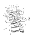
- Fig. 2 The leading to the e-scan antenna 12 cables are in Fig. 2 shown only schematically; By way of example, shown are an RF cable 26, which is connected via an angle plug 28 to the e-scan antenna 12, and an RF cable 30, which has an angled connector 32 for the connection.
- a bearing block 34 is fixedly arranged, such as on the mounting plate 58.
- a spherical bearing has a fixed in the bearing block 34 outer ring 38 and an inner ring 36 through which the wiring harness 24 is guided, which results from all individual cables in a suitable manner and, for example, by a sleeve 22, which is fastened by a fastening device, not shown, on the rear propeller shaft head 20.
- the distance between the front end of the wiring harness, such as the front end of the sleeve 22, and the bearing block 34 is about 13 centimeters.
- a first internal toothing 40 for driving the polarization ring 52 is used, a second internal toothing 42 for driving the front cone ring 54, and a third internal toothing 44 for driving the rear cone ring 56 are shown.
- a second internal toothing 42 for driving the front cone ring 54 is used, and a third internal toothing 44 for driving the rear cone ring 56 are shown.
- a third internal toothing 44 for driving the rear cone ring 56 is shown.
- the three internal gears 40, 42 and 44 only a short section is in each case Fig. 2 shown schematically, in fact, of course, these internal gears extend over the entire circumference.
- a power cable 16 millimeters in diameter is required; three data lines with each with a cross section of 17 millimeters, two liquid cooling pipes each with a cross section of 15 millimeters, and six RF cables with a cross section of 7 millimeters each.
- the repeater must be supplied with: three motor cables each 5 millimeters in diameter, and three 6-millimeter cable lines each for wiring the limit switches.
- this has a cross section of less than 70 millimeters, so that a value of 70 millimeters is sufficient for the free inner diameter of the inner ring 36 of the spherical bearing 36, 38.
- the propeller shaft 14 with the two ball joints 16, 20 can be (aviation approved) obtained from RWG Frankenjura-Industrie Flugwerklager GmbH under the model name "Link Z-Mount", P / N 603448.
Landscapes
- Variable-Direction Aerials And Aerial Arrays (AREA)
- Details Of Aerials (AREA)
Description
- Die Erfindung betrifft eine flexible Kabelführung. Im vorliegenden Zusammenhang sollen unter Kabel sowohl Kabel als auch Leitungen verstanden werden, also etwa Stromkabel für elektrischen Strom, Datenleitungen, Hochfrequenzkabel, Flüssigkeitsleitungen und dergleichen. Eine flexible Kabelführung ist immer dann erforderlich, wenn Kabel nicht starr an einem Gegenstand angebracht werden können, den sie versorgen sollen, da der Gegenstand in gewissem Ausmaß beweglich ist, so dass sich zumindest die Kabelenden in der Nähe des Gegenstandes mit diesem bewegen müssen.
- Weiterhin betrifft die Erfindung eine mit einer derartigen flexiblen Kabelführung versehene elektronisch gescannte Radarantenne, abgekürzt als E-Scan-Antenne bezeichnet. Derartige E-Scan-Antennen werden auch als AESA (Active Electronically Scanned Array) bezeichnet. Ein typisches Einsatzgebiet für E-Scan-Antennen sind moderne Kampfflugzeuge. So entwickelte Selex Galileo das AESA-Radarsystem des Typs Raven ES-05 für das Gripen-Programm; dieser Typ weist einen Taumelscheiben-Repositionierer (swashplate repositioner) auf. Weiterhin stellte Selex Galileo im Juli 2010 in Farnborough das Captor-E AESA-Radar für den Eurofighter Typhoon vor, welches ebenfalls einen Taumelscheiben-Repositionierer aufweist.
- Bei derartigen E-Scan-Antennen ist zwischen dem elektronisch erfolgenden Scan und der mechanischen Ausrichtung oder Positionierung/Repositionierung der E-Scan-Antenne zu unterscheiden.
- Der Erfindung liegt die Aufgabe zugrunde, eine flexible Kabelführung zur Verfügung zu stellen, mit welcher mehrere Kabel flexibel, also nicht starr, zu einem Gegenstand geführt werden können, der sich in gewissem Ausmaß bewegen kann. Diese Kabelführung soll auch bei einer E-Scan-Antenne einsetzbar sein, selbst unter den bei einem modernen Kampfflugzeug, beispielsweise des Typs Eurofighter Typhoon, auftretenden Betriebsbedingungen. Die Aufgabe wird gelöst durch eine Kabelführung mit einer Gelenkwelle, die einen ersten Gelenkwellenkopf an einem Ende eines Wellenstücks und einen zweiten Gelenkwellenkopf am anderen Ende des Wellenstücks aufweist, mit einer Vorrichtung zur Befestigung eines Kabelbaums am zweiten Gelenkwellenkopf, und mit einem Gelenklager, das im Abstand im Verlauf des Kabelbaums vom zweiten Gelenkwellenkopf ortsfest angeordnet und zum Durchführen des Kabelbaums ausgebildet ist.
- Bei dieser Kabelführung werden etwa dort, wo sich der zweite Gelenkwellenkopf befindet, die zum zu versorgenden Gegenstand führenden einzelnen Kabel zu einem Kabelbaum gebündelt, der dann durch das Gelenklager geführt wird.
- Bei einer Ausführungsform der Erfindung ist der erste und/oder der zweite Gelenkwellenkopf als Kugelgelenk ausgebildet. Jeder dieser Gelenkwellenköpfe kann jedoch auch beispielsweise als Kreuzgelenk oder Kardangelenk ausgebildet sein; es eignet sich im Prinzip jeder Gelenkwellenkopf, der die Kinematik ermöglicht, die durch die Art der Bewegung des zu versorgenden Gegenstandes vorgegeben ist.
- Bei einer Ausführungsform der Erfindung ist das Gelenklager als sphärisches Lager ausgebildet. Es lassen sich jedoch auch andere Gelenklager einsetzen, welche die für die Führung des Kabelbaums notwendige Kinematik ermöglichen.
- Weiterhin wird gemäß der Erfindung eine E-Scan-Antenne mit einer Kabelführung vorgeschlagen, die wie voranstehend geschildert ausgebildet ist, und mit einem Repositionierer versehen ist, an welchem das Gelenklager ortsfest angebracht ist, wobei der erste Gelenkwellenkopf an der E-Scan-Antenne angebracht ist.
- Hierdurch kann eine E-Scan-Antenne zur Verfügung gestellt werden, die zum Einsatz bei einem modernen Kampfflugzeug geeignet ist. Selbstverständlich ist die E-Scan-Antenne jedoch nicht auf Einsätze bei Kampfflugzeugen beschränkt, sondern lässt sich überall dort einsetzen, wo ein Radar mit einer E-Scan-Antenne eingesetzt werden soll.
- Bei einer Ausführungsform der Erfindung ist die E-Scan-Antenne so ausgebildet, dass der Repositionierer als Taumelscheiben-Repositionierer ausgebildet ist. Hierdurch lässt sich eine verlässliche und schnelle Positionierung oder Repositionierung der E-Scan-Antenne erzielen.
- Ist gemäß einer weiteren Ausführungsform der E-Scan-Antenne gemäß der Erfindung der Repositionier als Doppel-Taumelscheiben-Repositionierer ausgebildet, so wird hiermit eine erhöhte Variabilität der Repositionierung erzielt, allerdings verbunden mit einem erhöhten mechanischen Aufwand.
- Bei einer Ausführungsform der E-Scan-Antenne gemäß der Erfindung weist der Repositionierer zumindest eine Innenverzahnung auf. Durch eine derartige Innenverzahnung wird eine verlässliche und exakte Verstellung des Repositionierers ermöglicht.
- Hierzu ist gemäß einer weiteren Ausführungsform der Erfindung bei jeder Innenverzahnung ein Elektromotor für deren Antrieb vorgesehen, und ist für jeden Elektromotor eine Anordnung mit zwei Endschaltern zur Begrenzung des Drehwinkels der jeweiligen Innenverzahnung vorgesehen. Auf diese Weise lässt sich der Drehwinkel zuverlässig begrenzen.
- Nachfolgend wird anhand der beigefügten Zeichnungen näher auf Ausführungsbeispiele der Erfindung eingegangen. Es zeigt:
-
Fig. 1 eine E-Scan-Antenne mit einem Doppel-Taumelscheiben-Repositionierer; und -
Fig. 2 eine perspektivische Ansicht einer Kabelführung mit einer E-Scan-Antenne gemäß der Erfindung. - In den
Figuren 1 und2 ist mit x die Längsachse eines Kampfflugzeuges bezeichnet, mit y die Querachse, und mit z die Gier-Achse, was den drei Bewegungen Rollen (x), Nicken (y) bzw. Gieren (z) entspricht. - In
Fig. 1 ist eine E-Scan-Antenne 12 in ihrer maximal nach oben (in Richtung z) verkippten Ausrichtung dargestellt. Mit Hilfe eines Polarisationsringes 52 lässt sich die E-Scan-Antenne 12 drehen, was zur Beibehaltung der Polarisationsebene der von der E-Scan-Antenne 12 abgestrahlten elektromagnetischen Energie dient, wenn die E-Scan-Antenne 12 durch die Doppel-Taumelscheiben-Anordnung verstellt wird, die durch einen vorderen Konusring 54 und einen hinteren Konusring 56 gebildet wird. Weiterhin weist der Repositionierer 50 eine Befestigungsplatte 58 auf, mit welcher die gesamte inFig. 1 dargestellte Anordnung aus E-Scan-Antenne 12 und Repositionierer 50 an der Struktur des Flugzeuges angebracht wird. Der Repositionierer 50 umfasst dabei die mit den Bezugszeichen 52, 54, 56, 58 bezeichneten Teile. - Mit der in
Fig. 2 dargestellten Kabelführung 10 wird erreicht, dass sämtliche für die Versorgung der E-Scan-Antenne 12 erforderlichen Kabel sicher und verlässlich durch den Repositionierer 50 geführt werden, auch wenn die E-Scan-Antenne 12 sämtliche zulässigen Bewegungen ausführt, die durch den Polarisationsring 52, den vorderen Konusring 54 und den hinteren Konusring 56 ermöglicht werden. - An der Rückseite der E-Scan-Antenne 12 ist eine Halterung 23 vorgesehen, an welcher ein vorderer (Begriffe wie vorne und hinten beziehen sich auf das Flugzeug, an dessen vorderem Ende die E-Scan-Antenne 12 angebracht ist) Gelenkwellenkopf 16 an einer Gelenkwelle 14 angebracht ist. Die Gelenkwelle 14 weist über den Gelenkwellenkopf 16 hinaus ein Wellenstück 18 und einen hinteren Gelenkwellenkopf 20 auf. Die beiden Gelenkwellenköpfe 16, 20 sind jeweils als Kugelgelenk ausgebildet. Die Länge der gesamten Gelenkwelle 14 beträgt etwa 8 Zentimeter.
- Die zur E-Scan-Antenne 12 führenden Kabel sind in
Fig. 2 nur schematisch dargestellt; beispielhaft sind gezeigt ein HF-Kabel 26, das über einen Winkelstecker 28 an die E-Scan-Antenne 12 angeschlossen ist, sowie ein HF-Kabel 30, das einen Winkelstecker 32 für den Anschluss aufweist. - Ein Lagerbock 34 ist ortsfest angeordnet, etwa auf der Befestigungsplatte 58. Ein sphärisches Lager weist einen in dem Lagerbock 34 festgelegten Außenring 38 und einen Innenring 36 auf, durch welchen der Kabelbaum 24 geführt ist, der dadurch entsteht, dass sämtliche einzelnen Kabel auf geeignete Art und Weise, beispielsweise durch eine Manschette 22, gebündelt werden, die durch eine nicht dargestellte Befestigungsvorrichtung am hinteren Gelenkwellenkopf 20 befestigt ist. Der Abstand zwischen dem vorderen Ende des Kabelbaums, etwa dem vorderen Ende der Manschette 22, und dem Lagerbock 34 beträgt etwa 13 Zentimeter.
- Die in
Fig. 2 durch Doppelpfeile angedeuteten Drehwinkel um die z-Achse bzw. die y-Achse betragen jeweils ± 45 Grad. Der Aufwand zur Versorgung der E-Scan-Antenne 12, die selbst etwa 100 Kilogramm wiegt, ist beträchtlich, da die abgestrahlte Sendeleistung 8 kW beträgt. Es sind daher entsprechende Kabelquerschnitte für die Versorgung der E-Scan-Antenne 12 erforderlich, sowohl bei Stromkabeln als auch bei Flüssigkühlleitungen. Hinzu kommt die Stromversorgung für drei Elektromotoren zum Antrieb des Polarisationsrings 52, des vorderen Konusrings 54, und des hinteren Konusrings 56, wobei inFig. 2 eine erste Innenverzahnung 40 zum Antrieb des Polarisationsrings 52 dient, eine zweite Innenverzahnung 42 zum Antrieb des vorderen Konusrings 54, und eine dritte Innenverzahnung 44 zum Antrieb des hinteren Konusrings 56 gezeigt sind. Von den drei Innenverzahnungen 40, 42 und 44 ist jeweils nur ein kurzer Abschnitt inFig. 2 schematisch dargestellt, tatsächlich erstrecken sich natürlich diese Innenverzahnungen jeweils über den vollständigen Umfang. - Im Einzelnen sind zur Versorgung der E-Scan-Antenne 12 erforderlich: ein Stromkabel mit einem Durchmesser von 16 Millimeter; drei Datenleitungen mit einem Querschnitt von jeweils 17 Millimeter, zwei Flüssigkühlleitungen mit einem Querschnitt von jeweils 15 Millimeter, und sechs HF-Kabel mit einem Querschnitt von jeweils 7 Millimeter. Der Repositionierer muss versorgt werden mit: drei Motorstromkabeln mit einem Durchmesser von jeweils 5 Millimeter, und drei Verkabelungsleitungen mit einem Durchmesser von jeweils 6 Millimeter für die Verkabelung der Endschalter.
- Durch die Manschette 22 zu einem Kabelbaum 24 zusammengefügt weist dieser einen Querschnitt von weniger als 70 Millimeter auf, so dass für den freien Innendurchmesser des Innenrings 36 des sphärischen Lagers 36, 38 ein Wert von 70 Millimeter ausreichend ist.
- Die Gelenkwelle 14 mit den beiden Kugelgelenken 16, 20 kann (Luftfahrtzugelassen) bezogen werden von RWG Frankenjura-Industrie Flugwerklager GmbH unter der Modellbezeichnung "Link Z-Mount", P/N 603448.
-
- 10
- Kabelführung
- 12
- E-Scan-Antenne
- 14
- Gelenkwelle
- 16
- (vorderer) Gelenkwellenkopf (Kugelgelenk)
- 18
- Wellenstück
- 20
- (hinterer) Gelenkwellenkopf
- 22
- Manschette
- 23
- Halterung (für 16)
- 24
- Kabelbaum
- 26
- HF-Kabel
- 28
- Winkelstecker
- 30
- HF-Kabel
- 32
- Winkelstecker
- 34
- Lagerbock
- 36, 38
- sphärisches Lager
- 36
- Innenring
- 38
- Außenring
- 40
- erste Innenverzahnung (für 52)
- 42
- zweite Innenverzahnung (für 54)
- 44
- dritte Innenverzahnung (für 56)
- 46
- 48
- 50
- Repositionierer
- 52
- Polarisationsring
- 54
- vorderer Konusring
- 56
- hinterer Konusring
- 58
- Befestigungsplatte
Claims (8)
- Kabelführung (10) mit einer Gelenkwelle (14), die einen ersten Gelenkwellenkopf (16) an einem Ende eines Wellenstücks (18) und einen zweiten Gelenkwellenkopf (20) am anderen Ende des Wellenstücks (18) aufweist, mit einer Vorrichtung zur Befestigung eines Kabelbaums (24) am zweiten Gelenkwellenkopf (20), und mit einem Gelenklager (36, 38), das im Abstand im Verlauf des Kabelbaums (24) vom zweiten Gelenkwellenkopf (20) ortsfest angeordnet und zum Durchführen des Kabelbaums (24) ausgebildet ist.
- Kabelführung nach Anspruch 1, bei welche der erste (16) und/oder der zweite Gelenkwellenkopf (20) als Kugelgelenk ausgebildet ist.
- Kabelführung nach Anspruch 1 oder 2, bei welcher das Gelenklager als sphärisches Lager (36, 38) ausgebildet ist.
- E-Scan-Antenne (12) mit einer Kabelführung (10) nach einem der Ansprüche 1 bis 3, und mit einem Repositionierer (50), an welchem das Gelenklager (36, 38) ortsfest angebracht ist, wobei der erste Gelenkwellenkopf (16) an der E-Scan-Antenne (12) angebracht ist.
- E-Scan-Antenne nach Anspruch 4, bei welcher der Repositionierer als Taumelscheiben-Repositionierer ausgebildet ist.
- E-Scan-Antenne nach Anspruch 4, bei welcher der Repositionierer als Doppel-Taumelscheiben-Repositionierer (50) ausgebildet ist.
- E-Scan-Antenne nach einem der Ansprüche 4 bis 6, bei welcher der Repositionierer (50) zumindest eine Innenverzahnung (40; 42; 44) aufweist.
- E-Scan-Antenne nach Anspruch 7, bei welcher für jede Innenverzahnung (40; 42; 44) ein Elektromotor für deren Antrieb vorgesehen ist, und für jeden Elektromotor zwei Endschalter zur Begrenzung des Drehwinkels der jeweiligen Innenverzahnung vorgesehen sind.
Applications Claiming Priority (1)
| Application Number | Priority Date | Filing Date | Title |
|---|---|---|---|
| DE102012012411.2A DE102012012411B4 (de) | 2012-06-25 | 2012-06-25 | Flexible Kabelführung |
Publications (3)
| Publication Number | Publication Date |
|---|---|
| EP2680384A2 true EP2680384A2 (de) | 2014-01-01 |
| EP2680384A3 EP2680384A3 (de) | 2015-11-04 |
| EP2680384B1 EP2680384B1 (de) | 2017-11-15 |
Family
ID=48670328
Family Applications (1)
| Application Number | Title | Priority Date | Filing Date |
|---|---|---|---|
| EP13003035.6A Active EP2680384B1 (de) | 2012-06-25 | 2013-06-13 | Flexible kabelführung |
Country Status (3)
| Country | Link |
|---|---|
| EP (1) | EP2680384B1 (de) |
| DE (1) | DE102012012411B4 (de) |
| ES (1) | ES2656616T3 (de) |
Family Cites Families (3)
| Publication number | Priority date | Publication date | Assignee | Title |
|---|---|---|---|---|
| DE10211212A1 (de) * | 2002-03-13 | 2003-09-25 | Andries Broekhuijsen | Roboterleitungsführungsvorrichtung |
| JP2007159369A (ja) * | 2005-12-08 | 2007-06-21 | Sumitomo Wiring Syst Ltd | ケーブルのガイド装置 |
| US8602456B2 (en) * | 2010-12-09 | 2013-12-10 | Harris Corporation | Ball joint having a passageway for routing a cable therethrough |
-
2012
- 2012-06-25 DE DE102012012411.2A patent/DE102012012411B4/de active Active
-
2013
- 2013-06-13 ES ES13003035.6T patent/ES2656616T3/es active Active
- 2013-06-13 EP EP13003035.6A patent/EP2680384B1/de active Active
Also Published As
| Publication number | Publication date |
|---|---|
| EP2680384B1 (de) | 2017-11-15 |
| ES2656616T3 (es) | 2018-02-27 |
| DE102012012411A1 (de) | 2014-01-02 |
| DE102012012411B4 (de) | 2014-06-18 |
| EP2680384A3 (de) | 2015-11-04 |
Similar Documents
| Publication | Publication Date | Title |
|---|---|---|
| EP2233393B1 (de) | Verriegelungssystem | |
| WO2010149140A1 (de) | Halterung für einen bewegbaren sensor | |
| DE2419922A1 (de) | Taumelscheibenbaugruppe fuer ein drehfluegel-luftfahrzeug | |
| EP2640641B1 (de) | Schleppen eines flugzeugs mit fahrwerksadapter (verfahren und vorrichtung) | |
| DE10046248A1 (de) | Anti-Rotation Clip | |
| DE69110689T2 (de) | Kardangelenk für spielzeugkonstruktion. | |
| DE2410255A1 (de) | Kreuzrudersystem fuer eine rakete | |
| DE60100589T2 (de) | Gestängeanordnung für Steuerflächen eines Flugzeuges | |
| DE3217806C2 (de) | Vorrichtung zum ausfallsicheren Antrieb zweier Wellen, die über eine elastische Kupplung miteinander verbunden sind | |
| DE102011119946A1 (de) | Stellvorrichtung zum Positionieren eines Bauelements | |
| DE2011400C3 (de) | Kupplung zur Übertragung mindestens einer Drehbewegung von einem treibenden zu einem angetriebenen Ende und zur Winkelverstellung zwischen den beiden Enden, insbesondere für ein Drosselsteuergestänge eines Hubschraubers | |
| EP2680384B1 (de) | Flexible kabelführung | |
| DE102019118836B4 (de) | Adapteranordnung für eine Sattelzuganordnung | |
| DE202013007512U1 (de) | Kanalrohrinspektionsvorrichtung | |
| BE1028394B1 (de) | Automatisierte Ladevorrichtung zum konduktiven Laden von batterieelektrischen Fahrzeugen | |
| EP2467634B1 (de) | Halterung für einen bewegbaren sensor | |
| EP3911843B1 (de) | Vorrichtung zum antrieb einer welle eines strahltriebwerks zu inspektionszwecken | |
| DE3142135A1 (de) | Anordnung zur lagerung einer sonde an einem flugzeug | |
| DE102020205601B3 (de) | Getriebeanordnung für ein Schlagflügelfluggerät | |
| DE202019100924U1 (de) | Bildgebende medizinische Einrichtung | |
| DE102018123213A1 (de) | Roboter | |
| EP0342260B1 (de) | Flexible Kupplung für intermittierenden Betrieb, wie Schalterantrieb | |
| DE2534768C3 (de) | Stabilisierender Sockel | |
| DE102020115440A1 (de) | Automatisierte Ladevorrichtung zum konduktiven Laden von batterieelektrischen Fahrzeugen | |
| EP1635135A1 (de) | Flugkörperkopf und Verfahren zur Lenkung eines Flugkörpers |
Legal Events
| Date | Code | Title | Description |
|---|---|---|---|
| PUAI | Public reference made under article 153(3) epc to a published international application that has entered the european phase |
Free format text: ORIGINAL CODE: 0009012 |
|
| AK | Designated contracting states |
Kind code of ref document: A2 Designated state(s): AL AT BE BG CH CY CZ DE DK EE ES FI FR GB GR HR HU IE IS IT LI LT LU LV MC MK MT NL NO PL PT RO RS SE SI SK SM TR |
|
| AX | Request for extension of the european patent |
Extension state: BA ME |
|
| RAP1 | Party data changed (applicant data changed or rights of an application transferred) |
Owner name: AIRBUS DEFENCE AND SPACE GMBH |
|
| PUAL | Search report despatched |
Free format text: ORIGINAL CODE: 0009013 |
|
| AK | Designated contracting states |
Kind code of ref document: A3 Designated state(s): AL AT BE BG CH CY CZ DE DK EE ES FI FR GB GR HR HU IE IS IT LI LT LU LV MC MK MT NL NO PL PT RO RS SE SI SK SM TR |
|
| AX | Request for extension of the european patent |
Extension state: BA ME |
|
| RIC1 | Information provided on ipc code assigned before grant |
Ipc: H02G 3/32 20060101ALN20150929BHEP Ipc: F16L 3/16 20060101ALI20150929BHEP Ipc: H02G 11/00 20060101AFI20150929BHEP Ipc: B25J 19/00 20060101ALI20150929BHEP |
|
| 17P | Request for examination filed |
Effective date: 20160504 |
|
| STAA | Information on the status of an ep patent application or granted ep patent |
Free format text: STATUS: REQUEST FOR EXAMINATION WAS MADE |
|
| R17P | Request for examination filed (corrected) |
Effective date: 20160504 |
|
| RIC1 | Information provided on ipc code assigned before grant |
Ipc: B25J 19/00 20060101ALI20170629BHEP Ipc: F16L 3/16 20060101ALI20170629BHEP Ipc: H02G 11/00 20060101AFI20170629BHEP Ipc: H02G 3/32 20060101ALN20170629BHEP |
|
| GRAJ | Information related to disapproval of communication of intention to grant by the applicant or resumption of examination proceedings by the epo deleted |
Free format text: ORIGINAL CODE: EPIDOSDIGR1 |
|
| STAA | Information on the status of an ep patent application or granted ep patent |
Free format text: STATUS: GRANT OF PATENT IS INTENDED |
|
| GRAP | Despatch of communication of intention to grant a patent |
Free format text: ORIGINAL CODE: EPIDOSNIGR1 |
|
| INTG | Intention to grant announced |
Effective date: 20170818 |
|
| RIN1 | Information on inventor provided before grant (corrected) |
Inventor name: HOFFMANN, GERHARD |
|
| GRAS | Grant fee paid |
Free format text: ORIGINAL CODE: EPIDOSNIGR3 |
|
| GRAA | (expected) grant |
Free format text: ORIGINAL CODE: 0009210 |
|
| STAA | Information on the status of an ep patent application or granted ep patent |
Free format text: STATUS: THE PATENT HAS BEEN GRANTED |
|
| AK | Designated contracting states |
Kind code of ref document: B1 Designated state(s): AL AT BE BG CH CY CZ DE DK EE ES FI FR GB GR HR HU IE IS IT LI LT LU LV MC MK MT NL NO PL PT RO RS SE SI SK SM TR |
|
| REG | Reference to a national code |
Ref country code: CH Ref legal event code: EP Ref country code: GB Ref legal event code: FG4D Free format text: NOT ENGLISH Ref country code: AT Ref legal event code: REF Ref document number: 947154 Country of ref document: AT Kind code of ref document: T Effective date: 20171115 |
|
| REG | Reference to a national code |
Ref country code: IE Ref legal event code: FG4D Free format text: LANGUAGE OF EP DOCUMENT: GERMAN |
|
| REG | Reference to a national code |
Ref country code: DE Ref legal event code: R096 Ref document number: 502013008791 Country of ref document: DE |
|
| REG | Reference to a national code |
Ref country code: ES Ref legal event code: FG2A Ref document number: 2656616 Country of ref document: ES Kind code of ref document: T3 Effective date: 20180227 |
|
| REG | Reference to a national code |
Ref country code: NL Ref legal event code: MP Effective date: 20171115 |
|
| REG | Reference to a national code |
Ref country code: LT Ref legal event code: MG4D |
|
| PG25 | Lapsed in a contracting state [announced via postgrant information from national office to epo] |
Ref country code: NO Free format text: LAPSE BECAUSE OF FAILURE TO SUBMIT A TRANSLATION OF THE DESCRIPTION OR TO PAY THE FEE WITHIN THE PRESCRIBED TIME-LIMIT Effective date: 20180215 Ref country code: NL Free format text: LAPSE BECAUSE OF FAILURE TO SUBMIT A TRANSLATION OF THE DESCRIPTION OR TO PAY THE FEE WITHIN THE PRESCRIBED TIME-LIMIT Effective date: 20171115 Ref country code: FI Free format text: LAPSE BECAUSE OF FAILURE TO SUBMIT A TRANSLATION OF THE DESCRIPTION OR TO PAY THE FEE WITHIN THE PRESCRIBED TIME-LIMIT Effective date: 20171115 Ref country code: SE Free format text: LAPSE BECAUSE OF FAILURE TO SUBMIT A TRANSLATION OF THE DESCRIPTION OR TO PAY THE FEE WITHIN THE PRESCRIBED TIME-LIMIT Effective date: 20171115 Ref country code: LT Free format text: LAPSE BECAUSE OF FAILURE TO SUBMIT A TRANSLATION OF THE DESCRIPTION OR TO PAY THE FEE WITHIN THE PRESCRIBED TIME-LIMIT Effective date: 20171115 |
|
| PG25 | Lapsed in a contracting state [announced via postgrant information from national office to epo] |
Ref country code: GR Free format text: LAPSE BECAUSE OF FAILURE TO SUBMIT A TRANSLATION OF THE DESCRIPTION OR TO PAY THE FEE WITHIN THE PRESCRIBED TIME-LIMIT Effective date: 20180216 Ref country code: HR Free format text: LAPSE BECAUSE OF FAILURE TO SUBMIT A TRANSLATION OF THE DESCRIPTION OR TO PAY THE FEE WITHIN THE PRESCRIBED TIME-LIMIT Effective date: 20171115 Ref country code: BG Free format text: LAPSE BECAUSE OF FAILURE TO SUBMIT A TRANSLATION OF THE DESCRIPTION OR TO PAY THE FEE WITHIN THE PRESCRIBED TIME-LIMIT Effective date: 20180215 Ref country code: LV Free format text: LAPSE BECAUSE OF FAILURE TO SUBMIT A TRANSLATION OF THE DESCRIPTION OR TO PAY THE FEE WITHIN THE PRESCRIBED TIME-LIMIT Effective date: 20171115 Ref country code: RS Free format text: LAPSE BECAUSE OF FAILURE TO SUBMIT A TRANSLATION OF THE DESCRIPTION OR TO PAY THE FEE WITHIN THE PRESCRIBED TIME-LIMIT Effective date: 20171115 |
|
| PG25 | Lapsed in a contracting state [announced via postgrant information from national office to epo] |
Ref country code: DK Free format text: LAPSE BECAUSE OF FAILURE TO SUBMIT A TRANSLATION OF THE DESCRIPTION OR TO PAY THE FEE WITHIN THE PRESCRIBED TIME-LIMIT Effective date: 20171115 Ref country code: EE Free format text: LAPSE BECAUSE OF FAILURE TO SUBMIT A TRANSLATION OF THE DESCRIPTION OR TO PAY THE FEE WITHIN THE PRESCRIBED TIME-LIMIT Effective date: 20171115 Ref country code: CY Free format text: LAPSE BECAUSE OF FAILURE TO SUBMIT A TRANSLATION OF THE DESCRIPTION OR TO PAY THE FEE WITHIN THE PRESCRIBED TIME-LIMIT Effective date: 20171115 Ref country code: CZ Free format text: LAPSE BECAUSE OF FAILURE TO SUBMIT A TRANSLATION OF THE DESCRIPTION OR TO PAY THE FEE WITHIN THE PRESCRIBED TIME-LIMIT Effective date: 20171115 Ref country code: SK Free format text: LAPSE BECAUSE OF FAILURE TO SUBMIT A TRANSLATION OF THE DESCRIPTION OR TO PAY THE FEE WITHIN THE PRESCRIBED TIME-LIMIT Effective date: 20171115 |
|
| REG | Reference to a national code |
Ref country code: DE Ref legal event code: R097 Ref document number: 502013008791 Country of ref document: DE |
|
| PG25 | Lapsed in a contracting state [announced via postgrant information from national office to epo] |
Ref country code: PL Free format text: LAPSE BECAUSE OF FAILURE TO SUBMIT A TRANSLATION OF THE DESCRIPTION OR TO PAY THE FEE WITHIN THE PRESCRIBED TIME-LIMIT Effective date: 20171115 Ref country code: RO Free format text: LAPSE BECAUSE OF FAILURE TO SUBMIT A TRANSLATION OF THE DESCRIPTION OR TO PAY THE FEE WITHIN THE PRESCRIBED TIME-LIMIT Effective date: 20171115 Ref country code: SM Free format text: LAPSE BECAUSE OF FAILURE TO SUBMIT A TRANSLATION OF THE DESCRIPTION OR TO PAY THE FEE WITHIN THE PRESCRIBED TIME-LIMIT Effective date: 20171115 |
|
| PLBE | No opposition filed within time limit |
Free format text: ORIGINAL CODE: 0009261 |
|
| STAA | Information on the status of an ep patent application or granted ep patent |
Free format text: STATUS: NO OPPOSITION FILED WITHIN TIME LIMIT |
|
| PG25 | Lapsed in a contracting state [announced via postgrant information from national office to epo] |
Ref country code: MT Free format text: LAPSE BECAUSE OF FAILURE TO SUBMIT A TRANSLATION OF THE DESCRIPTION OR TO PAY THE FEE WITHIN THE PRESCRIBED TIME-LIMIT Effective date: 20171115 |
|
| 26N | No opposition filed |
Effective date: 20180817 |
|
| PG25 | Lapsed in a contracting state [announced via postgrant information from national office to epo] |
Ref country code: SI Free format text: LAPSE BECAUSE OF FAILURE TO SUBMIT A TRANSLATION OF THE DESCRIPTION OR TO PAY THE FEE WITHIN THE PRESCRIBED TIME-LIMIT Effective date: 20171115 |
|
| REG | Reference to a national code |
Ref country code: CH Ref legal event code: PL |
|
| REG | Reference to a national code |
Ref country code: BE Ref legal event code: MM Effective date: 20180630 |
|
| REG | Reference to a national code |
Ref country code: IE Ref legal event code: MM4A |
|
| PG25 | Lapsed in a contracting state [announced via postgrant information from national office to epo] |
Ref country code: LU Free format text: LAPSE BECAUSE OF NON-PAYMENT OF DUE FEES Effective date: 20180613 Ref country code: MC Free format text: LAPSE BECAUSE OF FAILURE TO SUBMIT A TRANSLATION OF THE DESCRIPTION OR TO PAY THE FEE WITHIN THE PRESCRIBED TIME-LIMIT Effective date: 20171115 |
|
| PG25 | Lapsed in a contracting state [announced via postgrant information from national office to epo] |
Ref country code: FR Free format text: LAPSE BECAUSE OF NON-PAYMENT OF DUE FEES Effective date: 20180630 Ref country code: IE Free format text: LAPSE BECAUSE OF NON-PAYMENT OF DUE FEES Effective date: 20180613 Ref country code: LI Free format text: LAPSE BECAUSE OF NON-PAYMENT OF DUE FEES Effective date: 20180630 Ref country code: CH Free format text: LAPSE BECAUSE OF NON-PAYMENT OF DUE FEES Effective date: 20180630 |
|
| PG25 | Lapsed in a contracting state [announced via postgrant information from national office to epo] |
Ref country code: BE Free format text: LAPSE BECAUSE OF NON-PAYMENT OF DUE FEES Effective date: 20180630 |
|
| REG | Reference to a national code |
Ref country code: AT Ref legal event code: MM01 Ref document number: 947154 Country of ref document: AT Kind code of ref document: T Effective date: 20180613 |
|
| PG25 | Lapsed in a contracting state [announced via postgrant information from national office to epo] |
Ref country code: AT Free format text: LAPSE BECAUSE OF NON-PAYMENT OF DUE FEES Effective date: 20180613 |
|
| PG25 | Lapsed in a contracting state [announced via postgrant information from national office to epo] |
Ref country code: TR Free format text: LAPSE BECAUSE OF FAILURE TO SUBMIT A TRANSLATION OF THE DESCRIPTION OR TO PAY THE FEE WITHIN THE PRESCRIBED TIME-LIMIT Effective date: 20171115 |
|
| PG25 | Lapsed in a contracting state [announced via postgrant information from national office to epo] |
Ref country code: PT Free format text: LAPSE BECAUSE OF FAILURE TO SUBMIT A TRANSLATION OF THE DESCRIPTION OR TO PAY THE FEE WITHIN THE PRESCRIBED TIME-LIMIT Effective date: 20171115 Ref country code: HU Free format text: LAPSE BECAUSE OF FAILURE TO SUBMIT A TRANSLATION OF THE DESCRIPTION OR TO PAY THE FEE WITHIN THE PRESCRIBED TIME-LIMIT; INVALID AB INITIO Effective date: 20130613 |
|
| PG25 | Lapsed in a contracting state [announced via postgrant information from national office to epo] |
Ref country code: MK Free format text: LAPSE BECAUSE OF NON-PAYMENT OF DUE FEES Effective date: 20171115 |
|
| PG25 | Lapsed in a contracting state [announced via postgrant information from national office to epo] |
Ref country code: AL Free format text: LAPSE BECAUSE OF FAILURE TO SUBMIT A TRANSLATION OF THE DESCRIPTION OR TO PAY THE FEE WITHIN THE PRESCRIBED TIME-LIMIT Effective date: 20171115 Ref country code: IS Free format text: LAPSE BECAUSE OF FAILURE TO SUBMIT A TRANSLATION OF THE DESCRIPTION OR TO PAY THE FEE WITHIN THE PRESCRIBED TIME-LIMIT Effective date: 20180315 |
|
| PGFP | Annual fee paid to national office [announced via postgrant information from national office to epo] |
Ref country code: DE Payment date: 20250618 Year of fee payment: 13 |
|
| PGFP | Annual fee paid to national office [announced via postgrant information from national office to epo] |
Ref country code: GB Payment date: 20250618 Year of fee payment: 13 |
|
| PGFP | Annual fee paid to national office [announced via postgrant information from national office to epo] |
Ref country code: ES Payment date: 20250728 Year of fee payment: 13 |
|
| PGFP | Annual fee paid to national office [announced via postgrant information from national office to epo] |
Ref country code: IT Payment date: 20250624 Year of fee payment: 13 |