EP2680187B1 - Abtasten eines optischen Codes - Google Patents
Abtasten eines optischen Codes Download PDFInfo
- Publication number
- EP2680187B1 EP2680187B1 EP13166533.3A EP13166533A EP2680187B1 EP 2680187 B1 EP2680187 B1 EP 2680187B1 EP 13166533 A EP13166533 A EP 13166533A EP 2680187 B1 EP2680187 B1 EP 2680187B1
- Authority
- EP
- European Patent Office
- Prior art keywords
- conveyor belt
- item
- scanner
- optical code
- determining
- Prior art date
- Legal status (The legal status is an assumption and is not a legal conclusion. Google has not performed a legal analysis and makes no representation as to the accuracy of the status listed.)
- Active
Links
Images



Classifications
-
- G—PHYSICS
- G06—COMPUTING OR CALCULATING; COUNTING
- G06K—GRAPHICAL DATA READING; PRESENTATION OF DATA; RECORD CARRIERS; HANDLING RECORD CARRIERS
- G06K7/00—Methods or arrangements for sensing record carriers, e.g. for reading patterns
- G06K7/10—Methods or arrangements for sensing record carriers, e.g. for reading patterns by electromagnetic radiation, e.g. optical sensing; by corpuscular radiation
- G06K7/10544—Methods or arrangements for sensing record carriers, e.g. for reading patterns by electromagnetic radiation, e.g. optical sensing; by corpuscular radiation by scanning of the records by radiation in the optical part of the electromagnetic spectrum
- G06K7/10821—Methods or arrangements for sensing record carriers, e.g. for reading patterns by electromagnetic radiation, e.g. optical sensing; by corpuscular radiation by scanning of the records by radiation in the optical part of the electromagnetic spectrum further details of bar or optical code scanning devices
- G06K7/10861—Methods or arrangements for sensing record carriers, e.g. for reading patterns by electromagnetic radiation, e.g. optical sensing; by corpuscular radiation by scanning of the records by radiation in the optical part of the electromagnetic spectrum further details of bar or optical code scanning devices sensing of data fields affixed to objects or articles, e.g. coded labels
-
- G—PHYSICS
- G06—COMPUTING OR CALCULATING; COUNTING
- G06K—GRAPHICAL DATA READING; PRESENTATION OF DATA; RECORD CARRIERS; HANDLING RECORD CARRIERS
- G06K7/00—Methods or arrangements for sensing record carriers, e.g. for reading patterns
- G06K7/10—Methods or arrangements for sensing record carriers, e.g. for reading patterns by electromagnetic radiation, e.g. optical sensing; by corpuscular radiation
- G06K7/10544—Methods or arrangements for sensing record carriers, e.g. for reading patterns by electromagnetic radiation, e.g. optical sensing; by corpuscular radiation by scanning of the records by radiation in the optical part of the electromagnetic spectrum
- G06K7/10821—Methods or arrangements for sensing record carriers, e.g. for reading patterns by electromagnetic radiation, e.g. optical sensing; by corpuscular radiation by scanning of the records by radiation in the optical part of the electromagnetic spectrum further details of bar or optical code scanning devices
- G06K7/10861—Methods or arrangements for sensing record carriers, e.g. for reading patterns by electromagnetic radiation, e.g. optical sensing; by corpuscular radiation by scanning of the records by radiation in the optical part of the electromagnetic spectrum further details of bar or optical code scanning devices sensing of data fields affixed to objects or articles, e.g. coded labels
- G06K7/10871—Methods or arrangements for sensing record carriers, e.g. for reading patterns by electromagnetic radiation, e.g. optical sensing; by corpuscular radiation by scanning of the records by radiation in the optical part of the electromagnetic spectrum further details of bar or optical code scanning devices sensing of data fields affixed to objects or articles, e.g. coded labels randomly oriented data-fields, code-marks therefore, e.g. concentric circles-code
-
- G—PHYSICS
- G06—COMPUTING OR CALCULATING; COUNTING
- G06K—GRAPHICAL DATA READING; PRESENTATION OF DATA; RECORD CARRIERS; HANDLING RECORD CARRIERS
- G06K7/00—Methods or arrangements for sensing record carriers, e.g. for reading patterns
- G06K7/10—Methods or arrangements for sensing record carriers, e.g. for reading patterns by electromagnetic radiation, e.g. optical sensing; by corpuscular radiation
- G06K7/10544—Methods or arrangements for sensing record carriers, e.g. for reading patterns by electromagnetic radiation, e.g. optical sensing; by corpuscular radiation by scanning of the records by radiation in the optical part of the electromagnetic spectrum
- G06K7/10821—Methods or arrangements for sensing record carriers, e.g. for reading patterns by electromagnetic radiation, e.g. optical sensing; by corpuscular radiation by scanning of the records by radiation in the optical part of the electromagnetic spectrum further details of bar or optical code scanning devices
- G06K7/1096—Methods or arrangements for sensing record carriers, e.g. for reading patterns by electromagnetic radiation, e.g. optical sensing; by corpuscular radiation by scanning of the records by radiation in the optical part of the electromagnetic spectrum further details of bar or optical code scanning devices the scanner having more than one scanning window, e.g. two substantially orthogonally placed scanning windows for integration into a check-out counter of a super-market
Definitions
- the present invention relates generally to improvements to optical code scanning. More particularly, but not exclusively, it relates to improvements to an optical code scanner, system and method.
- An assisted point of sale (POS)terminal is a POS terminal operated by a cashier.
- Customers present items for purchase and the cashier identifies each item by moving the item across an optical code scanner which reads an optical code in the form of a barcode attached to or printed on the item.
- the cashier is required to pick up and scan most of the items in the customer's purchase transaction.
- the present invention seeks to overcome or ameliorate at least one of the disadvantages of the prior art, or to provide a useful alternative.
- Claim 1 is delimited against US-A-5491328 .
- the invention is set out in claim 1.
- an optical code scanner comprising: a base housing defining a belt aperture in which a conveyor belt is mounted, and defining an upper surface; an upper housing extending upwards from the upper surface, and including an image capture device mounted therein and directed to cover a field of view above the upper surface; an imaging scanner operable to decode barcodes from an image captured by the image capture device.
- the base housing may further comprise a scanning aperture in registration with a scanning device mounted within the base housing and disposed adjacent to the conveyor belt and having a width of similar dimension to a width of the conveyor belt.
- the base housing may further comprise a plurality of scanning devices disposed in a linear arrangement matching an elongate shape of the scanning aperture, one of the scanning devices being located near one end of the linear arrangement and being disposed (i) transverse to another of the scanning devices and (ii) directed to cover a field of view above the upper surface and towards the upper housing.
- the base housing may further comprise a weigh scale coupled to the conveyor belt and operable to weigh an item located thereon.
- the scanner may include a motor operable to move the conveyor belt, under control of a computer, in a forward or reverse direction, to stop the conveyor belt, and to change a linear speed of the conveyor belt.
- the computer may control the motor in response to signals received from a foot pedal device.
- the optical code scanner may be incorporated into an optical code scanner according to the first aspect of the present invention.
- a method implemented by a computer in an optical code scanner comprising the steps of: (a) receiving an item presented to the scanner for identification; (b) causing a conveyor belt disposed in the scanner to move the item through the field of view of at least one of a plurality of image capture devices; (c) capturing at least one image of the item as it moves through the field of view; (d) processing the captured at least one image to decode data for an optical code captured in the image; (e) causing the conveyor belt to move the item off of the scanner on the side opposite the side it was received on when all processing is complete.
- the method may include the further steps of: (d.1) after step (d), determining whether the optical code data was decoded in step (d); (d.2) after step (d.1), upon determining the optical code data was decoded, transmitting the data on an external peripheral bus.
- the method may include the further steps of: (d.3) after step (d.1), upon determining that no optical code data was decoded, determining if the item has been rescanned at least once; (d.4) after step (d.3), upon determining the item has not been rescanned, performing the steps of: (d.5) reversing the direction of the conveyor belt; (d.6) after step (d.5), determining if the item has reached the scan area of the scanner and stopping the conveyor belt; and (d.7) after step (d.6), repeating steps (b)-(d).
- the method may include the further steps of: (d.8) after step (d.3), upon determining the item has been rescanned at least once, performing the steps of: (d.9) stopping the conveyor belt; (d.10) after step (d.9), sending a message requesting a cashier to identify the item; (d.11) after step (d.10), receiving a command to continue; (d.12) after step (d.11), starting the conveyor belt.
- the method may include the further steps of: (d.1) after step (d), transmitting the decoded data on an external peripheral bus; (d.2) after step (d.1), receiving a command to weigh the scanned item; (d.3) after step (d.2), stopping the conveyor belt; (d.4) after step (d.3), determining the weight of the scanned item on the conveyor belt using a weigh scale in the scanner where the conveyor belt is mounted on the weigh scale; (d.5) after step (d.4), transmitting the weight of the item on the external peripheral bus; and (d.6) after step (d.5), starting the conveyor belt.
- the method may include the further steps of: (b.1) receiving an input from a foot pedal device; (b.2) after step (b.1), determining the input is a command to stop the conveyor belt and stopping the conveyor belt.
- the method may include the further steps of: (b.3) after step (b.1), determining if the input is a command to start the conveyor belt and starting the conveyor belt.
- the method may include the further steps of: (b.4) after step (b.1), determining the input is a command to reverse the direction of the conveyor belt and reversing the direction the conveyor belt is moving.
- an optical code scanner for use in a point of sale terminal to read barcodes and weigh items presented for purchase, the scanner comprising: a base housing including a top surface wherein the top surface includes a first aperture; a weigh scale located within the base housing; a conveyor belt disposed within the first aperture and configured to move items from a receiving side of the base housing to the opposite side of the base housing and wherein the conveyor belt is attached to the weigh scale in a configuration that allows the weigh scale to determine the weight of any item on the conveyor belt; an upper housing mounted approximate to the rear and receiving side of the top surface and extending vertically above the top surface; an imaging optical code scanner including a first plurality of image capture devices disposed within the upper housing and configured to have fields of view directed across the top surface of the base housing; and wherein the conveyor belt is operable to receive an item from the receiving side of the base housing and wherein the imaging optical code scanner is operable to capture an image of a bar code on the item and decode the bar code and where the weigh scale is operable to determine the weight of the
- the conveyor belt may be operable to start, stop, change direction of movement and change the speed of movement.
- the scanner may further comprise a foot pedal device operable to provide input that causes the conveyor belt to start, stop and change direction.
- the scanner may further comprise a second aperture in the top surface of the base housing where the second aperture is narrow and long and where the long axis of the second aperture is perpendicular to the conveyor belt's direction of movement and proximate to the receiving side of the base housing.
- the second aperture may be filled with an optically transparent material.
- the imaging optical code scanner further comprises a second plurality of image capture devices disposed below the second aperture in an array configured to capture images that pass through the optically transparent material and to have fields of view that start at the top surface of the optically transparent material and extend upward.
- a point of sale terminal system comprising: an input conveyor belt operable to move items presented for purchase; and an optical code scanner, comprising: a base housing including a top surface wherein the top surface includes a first aperture where the first aperture extends over a substantial portion of the top surface; a weigh scale located within the base housing; a conveyor belt disposed within the first aperture and configured to receive items from the input conveyor belt on a receiving side of the base housing and move them to the opposite side of the base housing and wherein the conveyor belt is attached to the weigh scale in a configuration that allows the weigh scale to determine the weight of any item on the conveyor belt; an upper housing mounted proximate to the rear and receiving side of the top surface and extending vertically above the top surface; an imaging optical code scanner including a first plurality of image capture devices disposed within the upper housing and configured to have fields of view directed across the top surface of the base housing; and wherein the conveyor belt is operable to receive an item from the input conveyor belt and wherein the imaging optical code scanner is operable to capture an image of a
- the conveyor belt in the scanner may be operable to start, stop, change direction of movement and change the speed of movement.
- the system may further comprise a foot pedal device operable to provide input that causes the conveyor belt to start, stop and change direction.
- the scanner may further comprise a second aperture in the top surface of the base housing where the second aperture is narrow and long and located proximate to the receiving side such that items move over the second aperture as they move from the input conveyor belt onto the conveyor belt of the scanner.
- the second aperture may be filled with an optically transparent material.
- the imaging optical code scanner may further comprise a second plurality of image capture devices disposed below the second aperture in an array configured to capture images that pass through the optically transparent material and to have fields of view that start at the top surface of the optically transparent material and extend upward.
- one example recognizes a condition where a cashier of a point of sale terminal must pick up and move a large number of items over a period of time that in aggregate weigh many tons. This physical requirement lowers the cashier's job satisfaction and is one factor in the high turnover rate for cashiers.
- One example provides a conveyor belt integrated into an optical code scanner that moves items across or through the field of view of the optical code scanner. This reduces the number of items that a cashier must pick up and move for scanning.
- a scanner for use in a point of sale terminal to read barcodes and weigh items presented for purchase.
- a scanner may suitably comprise: a base housing including a top surface wherein the top surface includes a first aperture; a weigh scale located within the base housing; and a conveyor belt disposed within the first aperture and configured to move items from the receiving side of the base housing to the opposite side of the base housing and wherein the conveyor belt is attached to the weigh scale in a configuration that allows the weigh scale to determine the weight of any item on the conveyor belt.
- the scanner may further suitably comprise: an upper housing mounted to the rear and side of the top surface and extending vertically above the top surface; an imaging optical code scanner including a first plurality of image capture devices disposed within the upper housing and configured to have fields of view directed across the top surface of the base housing; and wherein the conveyor belt is operable to receive an item from one side of the base housing and move the item through the field of view of at least one of the plurality of image capture devices and wherein the imaging optical code scanner is operable to capture an image of a bar code on the item and decode the bar code and wherein the weigh scale is operable to determine the weight of the item on the conveyor belt.
- optical code includes machine-readable indicia that includes, but are not limited to, one-dimensional (1D)barcodes and two-dimensional (2D) barcodes.
- the POS terminal 100 includes a main housing 150, a computer housing 160 and a bag well 108.
- the main housing 150 includes an input conveyor belt 104, an optical code scanner/weigh scale 110 ("scanner”) and a take away conveyor belt 106.
- a magnetic stripe card reader 130 and a customer display 140 are attached to the main housing 150.
- the scanner 110 fits in a standard 12" (approximately 30.5cm) wide by 20" (approximately 50.8cm) long opening in the main housing 150.
- the computer housing 160 is attached to the main housing 150 and houses a computer unit ( Fig. 3 , 300) and further supports a cashier display and keyboard 120 on its top surface.
- a foot pedal device 165 is attached to the main housing 150.
- the foot pedal device 165 can be moved by a cashier to provide the best ease of use.
- the pedals on the foot pedal device 165 provide a user interface that allows the cashier to start, stop and reverse the direction of each conveyor belt controlled by the foot pedal device 165.
- the foot pedal device 165 is replaced by cashier operated switches and sensors that determine the presences of an item on a conveyor belt.
- the POS terminal 100 is designed to operate as an assisted terminal.
- a trained cashier operates the terminal 100 and stands on the near side of the POS terminal 100 next to foot pedal device 165.
- a customer wishing to purchase one or more items approaches the POS terminal 100 on the far side of the POS terminal 100 next to the input conveyor belt 104.
- the customer places the one or more items for purchase on the input conveyor belt 104 which transports each item to the scanner 110.
- the scanner 110 receives items from the input conveyor belt 104; scans each item by moving the item across the top of the scanner using a conveyor belt Fig. 2A , 225; and delivers each item to the take away belt 106.
- the scanner 110 identifies the item using a barcode on the item and determines the weight of the item if necessary.
- the take away conveyor belt 106 receives items from the scanner 110 and transports them to the bag well 108 for bagging.
- the cashier uses the foot pedal device 165 to control all the conveyor belts on the POS terminal 100.
- a processor using sensors tracks the movement of items on the conveyor belts and controls the movement of each conveyor belt relieving the cashier of most of the responsibility for controlling the conveyor belts.
- the customer display 140 displays details of the purchase transaction to the customer and the cashier display 120 displays details of the purchase transaction to the cashier.
- the magnetic stripe card reader 130 is used by the customer to read a credit or a debit card as one form of payment.
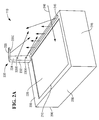
- Fig. 2A is a high-level drawing illustrating an exemplary embodiment of the optical code scanner/weigh scale 110.
- the scanner 110 includes a base housing 200 and an upper housing 230.
- the base housing 200 has six sides.
- Fig. 2A depicts a front side 215, a left side 220 and a top side 205. The other sides are depicted in Fig. 2B and Fig. 2C .
- the top side or surface 205 includes first aperture 210 and the second aperture 245.
- the second aperture 245 is long and narrow and is located proximate to the right edge of the top side 205.
- the second aperture 245 is filled with an optically clear material to create a window through the top side 205.
- Tempered float glass and sapphire on glass are examples of materials that can be used to fabricate the window.
- the first aperture 210 encompasses a significant portion of the top side 205.
- the conveyor belt 225 is located within and substantially fills the first aperture 210.
- the top of the conveyor belt 225 is flush with the top side 205.
- the conveyor belt 225 is designed to move items from one side of the scanner 110 to the other side of the scanner 110. In this example, items are received on the right side and moved to the left side as depicted by an arrow 240.
- the movement of the conveyor belt 225 can be reversed or stopped and the conveyor belt 225 has variable speeds.
- the left edge of the first aperture 210 is located proximate to the left edge of the top left side 220 to minimize the distance between the left edge of the first aperture 210 and the left edge of the top left side 220.
- the upper housing 230 is attached to the top side 205 near the rear of the right edge of the top side 205.
- the height of the upper housing 230 above the top side 205 is generally less than two feet (approximately 61cm). The actual height selected can vary depending on the size of items the system is designed to scan (in some embodiments the upper housing 230 may be height adjustable in situ, for example, using a telescopic arrangement).
- the upper housing 230 includes a first portion 232 that extends vertically from the top side 205 to a second portion 233.
- the second portion 233 extends upward at an angle from the vertical and generally out above a rear section of the second aperture 245.
- the first portion 232 includes a first image capture device 235A and a second image capture device 2358.
- the second portion 233 includes a third image capture device 235C.
- the image capture devices 235A-C are operable to capture images from their respective fields of view.
- Each image capture device comprises a CMOS image sensor to capture images.
- Other embodiments include additional or fewer image capture devices in different configurations and/or different locations within the upper housing 230.
- the viewing areas of the image capture devices 235A-C are generally directed toward the second aperture 245 or to an area above the second aperture 245.
- the arrows extending from each image capture device represent the general viewing direction of each image capture device 235A-C.
- illumination devices (notshown) are included in the upper housing 230 and the main housing 200.
- additional image capture devices are located below the second aperture 245 and designed to capture images through the second aperture 245. Their viewing areas are depicted by the arrows extending up through the second aperture 245.
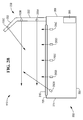
- Fig. 2B is a cross sectional view of the scanner 110 from the right side illustrating selected internal components.
- Located below the second aperture 245 are five image capture devices 265A-E. They are configured to capture images through the second aperture 245 as depicted.
- the front most image capture device 265A is aimed upward and toward the rear of the scanner 110 to receive and capture images of the sides of items passing through the scanner 110.
- the other image capture devices 265BE are aimed upward to receive and capture images of the bottom sides of items passing through the scanner 110.
- the arrows extending from each image capture device and depicts the general direction of the viewing area for each device.
- the main housing 200 further includes a bottom side 250, a rear side 260 and a computer unit 285 that controls the scanner 110.
- Fig. 2C is another cross sectional view of the scanner 110 from the front side 215 illustrating selected internal components.
- a weigh scale 270 is located within the main housing 200 and mounted to the bottom side 250. Two of the mounting attachments 274A-B are shown. Also, within the main housing 200 is the conveyer belt 225 which fills most of the first aperture 210. The conveyer belt 225 wraps around a drive pulley 276A and a tail pulley 276B. The pulleys 276A-B extend from the front of the main housing 200 to the rear of the main housing 200. Both the drive pulley 276A and tail pulley 276B are mounted to the weigh scale 270.
- the front end of the drive pulley 276A is fixed to an attachment 272A that is fixed to the weigh scale 270.
- the rear end of the drive pulley 276A is mounted to the weight scale 270 using a similar attachment (not shown).
- An electric motor 280 is mounted to the attachment 272A.
- the motor 280 drives the conveyor belt 225 using a drive belt 278 that connects the motor 280 to the drive pulley 276A.
- the motor 280 has variable speeds and can reverse directions.
- the front end of the tail pulley 276B is fixed to a second attachment 272B that is fixed to the weigh scale 270.
- the rear end of the tail pulley 276B is mounted to the weigh scale 270 using a similar attachment (notshown).
- All the components of the conveyor system are mounted to the weigh scale 270. To provide accurate weights for items on the conveyor belt 225, the components of the conveyor system is isolated from the main housing 200. The weight of the conveyor system is known and subtracted from any weight measured by the weigh scale 270. The remaining weight is the weight of whatever is resting on the conveyor belt 225.
- items moved from right to left across the scanner 110 In this embodiment, items moved from right to left across the scanner 110. However, in other embodiments, items moved from left to right by moving the upper housing 230 and second aperture 245 from the right side to the left side and shifting the first aperture 210 proximate to the right side 255.
- the computer unit 300 is located in the computer housing 160 of the POS terminal 100.
- the computer unit 300 includes a processor 350, a memory 355, control circuitry 360, a communications controller 370 and a video controller 375.
- the memory 355 includes both volatile and non-volatile memory.
- the non-volatile memory may include flash memory or other types of solid state electronic memory.
- Software stored in the memory 355 is executed by the processor 350 and causes the processor 350 to control the devices attached to the POS terminal 100 and to create the features and functions performed by the POS terminal 100.
- the control circuitry 360 provides an interface between the processor 350 and the memory 355 and between the processor 350 and a computer bus 365 used to control the communications controller 370 and the video controller 375.
- the communications controller 370 includes hardware and software required to communicate with external devices and peripherals over a computer peripheral network 380.
- the computer peripheral network 380 is implemented using the industry standard Universal Serial Bus (USB).
- USB Universal Serial Bus
- the computer peripheral network 380 may include wired or wireless communications links or both.
- the scanner 110, the magnetic card reader 130 and the foot pedal device 165 are connected to the computer peripheral network 380.
- the video controller 375 controls the information displayed on the cashier display 120 and the customer display 140.
- the foot pedal device 165 has a number of pedals that are used by the cashier to control the three conveyor belts on the POS terminal 100.
- the cashier can start, stop and reverse the conveyor belts using the pedals.
- the processor 350 of the POS terminal 100 receives the request from the foot pedal device 165 and sends a command to the scanner 110 over the computer peripheral network 380.
- the command causes the processor 310 to implement the request from the foot pedal.
- the request can be to start, stop or reverse the conveyor belt 225.
- the input conveyor belt 104 and the take away conveyor belt 106 are controlled by switches on the main housing 150 and sensors are used to start and stop the conveyor belts when items are detected on the belts.
- the foot pedal device 165 only controls the conveyor belt 225 in the scanner 110 so the foot pedal device 165 is connected to and controlled by the scanner 110 instead of the processor 350 of the POS terminal 100.
- the scanner 110 includes the computer unit 285.
- the computer unit 285 includes a processor 310, a memory 315, control circuitry 320 and a communications controller 325.
- the memory 315 includes both volatile and non-volatile memory.
- the non-volatile memory may include flash memory or other types of solid state electronic memory.
- Software stored in the memory 315 is executed by the processor 310 and causes the processor 310 to control the devices attached to the scanner 110 and to create the features and functions performed by the scanner 110.
- the control circuitry 320 provides an interface between the processor 310 and the memory 315 and between the processor 310 and the communications controller 325.
- the communications controller 325 includes hardware and software required to communicate with external devices and peripherals over the first computer peripheral network 380 and a second computer peripheral network 330.
- the two computer peripheral networks 380, 330 are implemented using the industry standard Universal Serial Bus (USB).
- USB Universal Serial Bus
- the computer peripheral networks 380,330 may include wired or wireless communications links or both.
- the scanner 110 uses the second computer peripheral network 330 to control the conveyor belt motor 280, the imaging scanner 305 and the weigh scale 270.
- the conveyer belt motor 280 is controlled by the processor 310 and can be operated at different speeds and in a forward and a reverse direction.
- the forward direction moves items from the right side to the left side of the scanner 100. Unless otherwise stated, when the conveyor belt 225 is started, it is moving in the forward direction.
- the imaging scanner 305 includes all the image capture devices 265A-E, 225A-C and any illumination devices.
- the imaging scanner 305 captures images using the image capture devices 265A-E, 225A-C and processes the images to identify and decode optical codes.
- the imaging scanner 305 is controlled by the processor 310.
- the processor 310 processes the captured images and decodes the optical code.
- the imaging scanner 305 includes a separate processor that processes the captured images and decodes the optical code.
- the weigh scale 270 is controlled by the processor 310 and is used to determine the weight of an item on the conveyor belt 225.
- the scanner 110 moves the item to the middle of the scanner 110 and stops the conveyor belt 225.
- the weight of the item is determined by the weigh scale 270.
- the scanner 110 sends the weight to the POS terminal 100 and starts the conveyor belt 225 to move the item to the take away belt 106.
- An item sold by weight can be automatically identified by a barcode attached to the item and scanned by the scanner 110 or by using a manual process where the cashier identifies the item and instruct the POS terminal 100 to have the scanner 110 weigh it.
- the scanner 110 When an item passes through the scanning area of the scanner 110 and is not identified, the scanner 110 will cause the conveyor belt 225 to reverse direction until the item is moved back into the scanning area to attempt to rescan the item for identification. If the second attempt to identify the item fails, a message will be displayed on the cashier display 120 requesting that the cashier identify the item.
- the scanner 110 also sends the POS terminal 100 a command to stop the input conveyor belt 104 when the scanner 110 attempts to rescan an item. When the item is identified, the scanner 110 sends a command to the POS terminal 100 to start the input conveyor belt 104.
- the number of rescans is a software parameter and can be set to a plurality of the different values by an administrator of the POS terminal 100.
- Fig. 4 is a high-level flow chart illustrating an exemplary method 400 of operating the scanner 110.
- an item is received for identification by the scanner 110.
- the item is delivered to the scanner 110 by the input conveyor belt 104.
- the item is moved through the scan area using the conveyor belt 225 in the scanner 110. As the item moves off the input conveyor belt 104, it moves onto the scanner's 110 conveyor belt 225.
- the scan area comprises the general area between the two conveyor belts 225,104 and an area over the right end of the conveyor belt 225.
- the second aperture 245 is located on the top side 205 of the scanner 110 in the area between the two conveyor belts 225, 104.
- the area between the input conveyor belt 104 and the conveyor belt 225 on the scanner 110 is relatively small.
- the input conveyor belt 104 pushes average sized items across the area and partially onto the scanner's 110 conveyor belt 225.
- the partial contact with the conveyor belt 225 is sufficient in most cases for the item to be captured by the conveyor belt 225 and moved across the scanner 110.
- the cashier may have to nudge the item onto the conveyor belt 225 but this is still an improvement of over picking up each item.
- images of the item are captured by image capture devices 235A-C located in the upper housing 230 and by image capture devices 265A-E located under the second aperture 245.
- the captured images are processed to decode data for any barcode that was captured.
- Step 420 determines if a barcode was found and the data decoded. If a barcode was decoded, the method continues to step 423. If a barcode was not decoded, the method continues to step 435. At step 423, the decoded barcode data is transmitted to the POS terminal 100 over the computer peripheral network 380. At step 425, it is determined if a command has been received to weigh the item. The POS terminal 100 determines if the identified item is sold by weight and must be weighed. Therefore, the POS terminal must send a command that causes the scanner 110 to weigh the item if it is sold by weight. If a weigh command has been received, control is transferred to step 460. If no command has been received, the method continues at step 430. At step 430, the item moved off the scanner 110 using the conveyor belt 225. In some embodiments, the item is moved onto the take away belt 106 which delivers the item to the bag well 108.
- the following section of the method 400 weighs the item on the conveyor belt 225.
- the conveyor belt 225 is stopped. This removes any vibrations that might prevent an accurate weight reading.
- the weight of the item is determined by the weigh scale 270.
- the weight of the item is determined by taking the weight of the item and all the elements mounted on the weigh scale 270 and subtracting the known weight of all the elements mounted on the weigh scale 270.
- the weight of the item is transmitted to the POS terminal 100 over the computer peripheral network 380.
- the conveyor belt 225 is started and control is transferred to step 430.
- the following section of the method 400 is used to rescan an item that was not scanned on the first try.
- the method 400 allows an item to be rescanned once. However, other embodiments permit additional rescans as a software selectable option.
- step 435 it is determined if the item has been rescanned and the rescanned failed. If it has, control passes to step 480. If the item has not been rescanned, control passes to step 440.
- the direction of the conveyor belt 225 is reversed which moves the item back into the scan area.
- the direction of the conveyor belt 225 is changed back to the forward direction.
- sensors are used to determine when an item is in the scan area.
- one or more of the image capture devices are used to capture images that are processed to determine the location of the item and when it is the scan area. Control then passes to step 405 where more images are captured in an attempt to read a barcode on the item.
- step 480 the conveyor belt 225 is stopped with the item still on it.
- step 485 a message is sent for display on the cashier display 120.
- the message requests that the cashier identify the item on the conveyor belt 225.
- the message is transmitted on the computer peripheral network 380 to the POS terminal 100.
- step 490 it is determined if a command to continue has been received.
- the cashier enters the identification for the item using the cashier keyboard 120 which it connected to the POS terminal's 100 processor 350. Before the scanner 110 can continue scanning items, the POS terminal's 100 processor 350 must send a continue command to the scanner 110. If the command has not been received, control passes back to step 490. If the command has been received, control passes to step 495.
- step 495 the conveyor belt 495 is started in the forward direction and control passes to step 425.
Landscapes
- Physics & Mathematics (AREA)
- Electromagnetism (AREA)
- Engineering & Computer Science (AREA)
- Health & Medical Sciences (AREA)
- General Health & Medical Sciences (AREA)
- Toxicology (AREA)
- Artificial Intelligence (AREA)
- Computer Vision & Pattern Recognition (AREA)
- General Physics & Mathematics (AREA)
- Theoretical Computer Science (AREA)
- Cash Registers Or Receiving Machines (AREA)
Claims (13)
- Optischer Codescanner (110), umfassend:ein Grundgehäuse (200), das eine Bandöffnung (210) definiert, in der ein Förderband (225) angebracht ist, und eine obere Fläche (205) definiert;ein oberes Gehäuse (230), das sich von der oberen Fläche (205) aufwärts erstreckt und eine Bilderfassungsvorrichtung (235) umfasst, die darin angebracht und derart gerichtet ist, dass sie ein Sichtfeld über der oberen Fläche (205) abdeckt; undeinen Bildscanner (305), der betriebsfähig ist, Barcodes von einem Bild zu decodieren, das von der Bilderfassungsvorrichtung (235) erfasst wurde, wobei das Grundgehäuse (200) weiter umfasst:eine Scanöffnung (245), die neben dem Förderband (225) angeordnet ist und eine Breite von ähnlicher Abmessung zu einer Breite des Förderbandes (225) aufweist; gekennzeichnet durchmehrere Scanner (265), die innerhalb des Grundgehäuses (200) angebracht und in einer linearen Anordnung angeordnet sind, die mit einer länglichen Form der Scanöffnung (245) übereinstimmt, wobei sich einer (265A) der Scanner (265) in der Nähe eines Endes der linearen Anordnung befindet und (i) transversal zu einem anderen (265B) von den Scannern (265) angeordnet ist und (ii) derart gerichtet ist, dass er ein Sichtfeld über der oberen Fläche (205) und in Richtung zu dem oberen Gehäuse (230) abdeckt.
- Optischer Codescanner (110) nach einem der vorstehenden Ansprüche, wobei das Grundgehäuse (200) weiter eine Waage (270) umfasst, die mit dem Förderband (225) gekoppelt und betriebsfähig ist, ein Element zu wiegen, das darauf angeordnet ist.
- Optischer Codescanner (110) nach einem der vorstehenden Ansprüche, wobei der Scanner (110) einen Motor (280) umfasst, der betriebsfähig ist, das Förderband (225) unter der Steuerung eines Computers (285, 300) in einer Vorwärts- oder Rückwärtsrichtung zu bewegen, um das Förderband (225) zu stoppen und eine Lineargeschwindigkeit des Förderbandes (225) zu ändern.
- Optischer Codescanner (110) nach Anspruch 3, wobei der Computer (300) den Motor (280) als Reaktion auf Signale steuert, die von einer Fußpedalvorrichtung (165) empfangen werden.
- Kassenterminal (100), das den optischen Codescanner (110) nach einem der vorstehenden Ansprüche umfasst.
- Verfahren, das durch einen Computer in einem optischen Codescanner (110) implementiert ist, nach Anspruch 1, wobei das Verfahren die Schritte umfasst:(a) Empfangen eines Elements, das dem Scanner (110) zur Identifikation präsentiert wird;(b) Bewirken, dass ein Förderband (225), das in einer Bandöffnung (210) eines Grundgehäuses (200) des Scanners (110) angeordnet ist, das Element durch ein Sichtfeld von mindestens einer von mehreren Bilderfassungsvorrichtungen (235, 265) bewegt,(c) Erfassen von mindestens einem Bild des Elements, während es sich durch ein Sichtfeld von mindestens einer von den Bilderfassungsvorrichtungen (235, 265) bewegt;(d) Verarbeiten des erfassten mindestens einen Bildes, um Daten für einen optischen Code, der im Bild erfasst wurde, zu decodieren; und(e) Bewirken, dass das Förderband (225) das Element von dem Scanner (110) auf eine Seite (220) bewegt, die einer Seite (255), an der es empfangen wurde, gegenüberliegt, wenn die gesamte Verarbeitung abgeschlossen ist.
- Verfahren nach Anspruch 6, weiter umfassend die Schritte:(d.1) nach Schritt (d), Bestimmen, ob die optischen Codedaten in Schritt (d) decodiert wurden; und(d.2) nach Schritt (d.1), nach dem Bestimmen, dass die optischen Codedaten decodiert wurden, Übertragen der Daten auf einem externen Peripheriebus.
- Verfahren nach Anspruch 7, weiter umfassend die Schritte:(d.3) nach Schritt (d.1), nach dem Bestimmen, dass keine optischen Codedaten decodiert wurden, Bestimmen, ob das Element mindestens einmal erneut gescannt wurde;(d.4) nach Schritt (d.3), nach dem Bestimmen, dass das Element nicht erneut gescannt wurde, Ausführen der Schritte:(d.5) Umkehren der Richtung des Förderbandes (225)(d.6) nach Schritt (d.5), Bestimmen, dass das Element die Scanfläche des Scanners (110) erreicht hat, und Stoppen des Förderbandes (225); und(d.7) nach Schritt (d.6), Wiederholen der Schritte (b) bis (d).
- Verfahren nach Anspruch 8, weiter umfassend die Schritte:(d.8) nach Schritt (d.3), nach dem Bestimmen, dass das Element mindestens einmal erneut gescannt wurde, Ausführen der Schritte:(d.9) Stoppen des Förderbandes (225);(d.10) nach Schritt (d.9), Senden einer Nachricht, die einen Kassierer auffordert, das Element zu identifizieren;(d.11) nach Schritt (d.10), Empfangen eines Befehls, um fortzufahren;(d.12) nach Schritt (d.11), Starten des Förderbandes (225).
- Verfahren nach Anspruch 8, weiter umfassend die Schritte:(d.1) nach Schritt (d), Übertragen der decodierten Daten auf einem externen Peripheriebus;(d.2) nach Schritt (d.1), Empfangen eines Befehls, um das gescannte Element zu wiegen;(d.3) nach Schritt (d.2), Stoppen des Förderbandes (225);(d.4) nach Schritt (d.3), Bestimmen des Gewichts des gescannten Elements auf dem Förderband (225) unter Verwendung einer Waage (270) im Scanner (110), wobei das Förderband (225) auf der Waage (270) angebracht ist;(d.5) nach Schritt (d.4), Übertragen des Gewichts des Elements auf dem externen Peripheriebus; und(d.6) nach Schritt (d.5), Starten des Förderbandes.
- Verfahren nach einem der Ansprüche 6 bis 10, weiter umfassen die Schritte:(b.1) Empfangen eines Eingangs von einer Fußpedalvorrichtung (165);(b.2) nach Schritt (b.1), Bestimmen, dass der Eingang ein Befehl zum Stoppen des Förderbandes ist, und Stoppen des Förderbandes (225).
- Verfahren nach Anspruch 11, weiter den Schritt umfassend:(b.3) nach Schritt (b.1), Bestimmen, dass der Eingang ein Befehl zum Starten des Förderbandes (225) ist, und Starten des Förderbandes (225).
- Verfahren nach Anspruch 12, weiter den Schritt umfassend:(b.4) nach Schritt (b.1), Bestimmen, dass der Eingang ein Befehl zum Umkehren der Richtung des Förderbandes (225) ist, und Umkehren der Richtung, in der sich das Förderband (225) bewegt.
Applications Claiming Priority (1)
| Application Number | Priority Date | Filing Date | Title |
|---|---|---|---|
| US13/538,080 US8960549B2 (en) | 2012-06-29 | 2012-06-29 | Method, apparatus and system for scanning an optical code |
Publications (3)
| Publication Number | Publication Date |
|---|---|
| EP2680187A2 EP2680187A2 (de) | 2014-01-01 |
| EP2680187A3 EP2680187A3 (de) | 2014-03-26 |
| EP2680187B1 true EP2680187B1 (de) | 2016-10-26 |
Family
ID=48326146
Family Applications (1)
| Application Number | Title | Priority Date | Filing Date |
|---|---|---|---|
| EP13166533.3A Active EP2680187B1 (de) | 2012-06-29 | 2013-05-03 | Abtasten eines optischen Codes |
Country Status (3)
| Country | Link |
|---|---|
| US (1) | US8960549B2 (de) |
| EP (1) | EP2680187B1 (de) |
| CN (1) | CN103544460B (de) |
Families Citing this family (11)
| Publication number | Priority date | Publication date | Assignee | Title |
|---|---|---|---|---|
| USD702237S1 (en) * | 2013-01-11 | 2014-04-08 | Hand Held Products, Inc. | Imaging terminal |
| EP3087877B1 (de) * | 2015-04-29 | 2021-06-02 | Wincor Nixdorf International GmbH | Kassensystemanordnung mit warentrennstaberkennung |
| CN105160774B (zh) * | 2015-07-31 | 2017-12-05 | 浙江立芯信息科技股份有限公司 | 餐厅智能结算终端 |
| WO2018151008A1 (ja) * | 2017-02-14 | 2018-08-23 | 日本電気株式会社 | 画像認識システム、画像認識方法及び記録媒体 |
| JP2019153111A (ja) * | 2018-03-05 | 2019-09-12 | 東芝テック株式会社 | 読取装置 |
| USD908704S1 (en) * | 2018-11-06 | 2021-01-26 | Lumiradx Uk Ltd | Reader |
| US11176529B2 (en) * | 2019-09-27 | 2021-11-16 | Ncr Corporation | Produce identification, weight, and checkout verification processing |
| CN111591661A (zh) * | 2020-06-24 | 2020-08-28 | 深圳蓝胖子机器人有限公司 | 一种仓库拣货方法、系统 |
| JP7514693B2 (ja) * | 2020-08-13 | 2024-07-11 | 東芝テック株式会社 | 決済装置 |
| JP7505939B2 (ja) * | 2020-08-21 | 2024-06-25 | 東芝テック株式会社 | 決済装置 |
| US12353949B2 (en) * | 2023-04-27 | 2025-07-08 | Zebra Technologies Corporation | Indicia tracking and decoding systems |
Family Cites Families (12)
| Publication number | Priority date | Publication date | Assignee | Title |
|---|---|---|---|---|
| US3807129A (en) * | 1972-07-24 | 1974-04-30 | K Freidel | Bagging machine |
| US4178671A (en) * | 1977-08-04 | 1979-12-18 | Dale Luttig | Tie preplating method and apparatus |
| US5491328A (en) | 1991-09-24 | 1996-02-13 | Spectra-Physics Scanning Systems, Inc. | Checkout counter scanner having multiple scanning surfaces |
| US5426282A (en) * | 1993-08-05 | 1995-06-20 | Humble; David R. | System for self-checkout of bulk produce items |
| US5770848A (en) * | 1994-11-28 | 1998-06-23 | Hitachi, Ltd. | Apparatus and method for treating a commodity by automatically recognizing a barcode attached to a conveyed commodity by scanner |
| JPH08221659A (ja) * | 1995-02-09 | 1996-08-30 | Hitachi Ltd | 自動精算方法及びその装置 |
| US6286758B1 (en) | 1999-02-17 | 2001-09-11 | Ncr Corporation | Reconfigurable checkout system |
| US6263789B1 (en) * | 2000-03-09 | 2001-07-24 | Ora Corporation | Machine for automatically sizing and positioning filling material upon randomly spaced tortillas advancing upon conveyor |
| US8286877B2 (en) * | 2005-06-13 | 2012-10-16 | Datalogic ADC, Inc. | System and method for data reading using raster scanning |
| DE102009037124A1 (de) | 2009-08-11 | 2011-02-17 | Wincor Nixdorf International Gmbh | Vorrichtung und Verfahren zum optischen Abtasten einer maschinenlesbaren Markierung |
| CN103329144B (zh) * | 2011-01-24 | 2016-08-31 | 数据逻辑Adc公司 | 用于验货台的模块化扫描器部件安装系统 |
| US20120223141A1 (en) * | 2011-03-01 | 2012-09-06 | Metrologic Instruments, Inc. | Digital linear imaging system employing pixel processing techniques to composite single-column linear images on a 2d image detection array |
-
2012
- 2012-06-29 US US13/538,080 patent/US8960549B2/en active Active
-
2013
- 2013-05-03 EP EP13166533.3A patent/EP2680187B1/de active Active
- 2013-06-27 CN CN201310260960.7A patent/CN103544460B/zh active Active
Non-Patent Citations (1)
| Title |
|---|
| None * |
Also Published As
| Publication number | Publication date |
|---|---|
| US20140001266A1 (en) | 2014-01-02 |
| EP2680187A3 (de) | 2014-03-26 |
| US8960549B2 (en) | 2015-02-24 |
| CN103544460A (zh) | 2014-01-29 |
| EP2680187A2 (de) | 2014-01-01 |
| CN103544460B (zh) | 2016-09-28 |
Similar Documents
| Publication | Publication Date | Title |
|---|---|---|
| EP2680187B1 (de) | Abtasten eines optischen Codes | |
| JP4672725B2 (ja) | 二次元ターゲットのイメージキャプチャを含む、一次元印の電気光学読取り用取引地点ワークステーション | |
| US5252814A (en) | Multi-scanner checkout counter using digitizer panel to determine X-Y location of scanned items | |
| US11783681B2 (en) | Bioptical barcode reader | |
| EP2565819B1 (de) | Verfahren und Vorrichtung zur Bereitstellung kundenseitiger Bildgebung sowie von Strichcodeabtastungs-Bildgebung | |
| US20100252635A1 (en) | Exposure control for multi-imaging scanner | |
| CA2882883C (en) | Checkout system for and method of preventing a customer-operated accessory reader facing a bagging area from imaging targets on products passed through a clerk-operated workstation to the bagging area | |
| US20110220720A1 (en) | Code reading apparatus, sales registration processing apparatus, and code reading method | |
| US8870073B2 (en) | Methods and apparatus for positioning an optical code for imaging scanning | |
| WO2010075016A1 (en) | Imaging of non-barcoded documents | |
| EP2308008A1 (de) | Multi-bildgebungsscanner zum lesen mehrerer bilder | |
| US9797766B2 (en) | Application for and method of preventing overhanging weighing platter of scale from tipping at product checkout system and method of mounting and removing the weighing platter without tools | |
| EP2727046B1 (de) | Individuelle belichtungssteuerung über einzeln beleuchtete unterfelder einer geteilten ansicht einer bildgebungsvorrichtung in einem transaktionspunkt-arbeitsbereich | |
| US20120043385A1 (en) | Image capture based on working distance range restriction in imaging reader | |
| US20080296388A1 (en) | Compact, ergonomic imaging reader and method | |
| WO2008027170A2 (en) | Imaging reader with variable range | |
| US20080035732A1 (en) | Uniform illumination without specular reflection in imaging reader | |
| EP2693365B1 (de) | Abtastung optischer Kodes | |
| US8733651B2 (en) | Low profile tri-aperture optical code scanner | |
| EP3018612B1 (de) | System und verfahren zur automatischen vermeidung von signalinterferenz zwischen produkt-proximity-subsystemen, die signale durch gegenüberstehende präsentationsfenster von verschiedenen arbeitsstationen aussenden |
Legal Events
| Date | Code | Title | Description |
|---|---|---|---|
| PUAI | Public reference made under article 153(3) epc to a published international application that has entered the european phase |
Free format text: ORIGINAL CODE: 0009012 |
|
| AK | Designated contracting states |
Kind code of ref document: A2 Designated state(s): AL AT BE BG CH CY CZ DE DK EE ES FI FR GB GR HR HU IE IS IT LI LT LU LV MC MK MT NL NO PL PT RO RS SE SI SK SM TR |
|
| AX | Request for extension of the european patent |
Extension state: BA ME |
|
| PUAL | Search report despatched |
Free format text: ORIGINAL CODE: 0009013 |
|
| AK | Designated contracting states |
Kind code of ref document: A3 Designated state(s): AL AT BE BG CH CY CZ DE DK EE ES FI FR GB GR HR HU IE IS IT LI LT LU LV MC MK MT NL NO PL PT RO RS SE SI SK SM TR |
|
| AX | Request for extension of the european patent |
Extension state: BA ME |
|
| RIC1 | Information provided on ipc code assigned before grant |
Ipc: G06K 7/10 20060101AFI20140217BHEP |
|
| 17P | Request for examination filed |
Effective date: 20140926 |
|
| RBV | Designated contracting states (corrected) |
Designated state(s): AL AT BE BG CH CY CZ DE DK EE ES FI FR GB GR HR HU IE IS IT LI LT LU LV MC MK MT NL NO PL PT RO RS SE SI SK SM TR |
|
| GRAP | Despatch of communication of intention to grant a patent |
Free format text: ORIGINAL CODE: EPIDOSNIGR1 |
|
| INTG | Intention to grant announced |
Effective date: 20160819 |
|
| GRAS | Grant fee paid |
Free format text: ORIGINAL CODE: EPIDOSNIGR3 |
|
| GRAA | (expected) grant |
Free format text: ORIGINAL CODE: 0009210 |
|
| REG | Reference to a national code |
Ref country code: DE Ref legal event code: R084 Ref document number: 602013013137 Country of ref document: DE |
|
| AK | Designated contracting states |
Kind code of ref document: B1 Designated state(s): AL AT BE BG CH CY CZ DE DK EE ES FI FR GB GR HR HU IE IS IT LI LT LU LV MC MK MT NL NO PL PT RO RS SE SI SK SM TR |
|
| REG | Reference to a national code |
Ref country code: GB Ref legal event code: FG4D |
|
| REG | Reference to a national code |
Ref country code: CH Ref legal event code: EP |
|
| REG | Reference to a national code |
Ref country code: AT Ref legal event code: REF Ref document number: 840500 Country of ref document: AT Kind code of ref document: T Effective date: 20161115 |
|
| REG | Reference to a national code |
Ref country code: IE Ref legal event code: FG4D |
|
| REG | Reference to a national code |
Ref country code: GB Ref legal event code: 746 Effective date: 20161108 |
|
| REG | Reference to a national code |
Ref country code: DE Ref legal event code: R096 Ref document number: 602013013137 Country of ref document: DE |
|
| REG | Reference to a national code |
Ref country code: LT Ref legal event code: MG4D |
|
| PG25 | Lapsed in a contracting state [announced via postgrant information from national office to epo] |
Ref country code: LV Free format text: LAPSE BECAUSE OF FAILURE TO SUBMIT A TRANSLATION OF THE DESCRIPTION OR TO PAY THE FEE WITHIN THE PRESCRIBED TIME-LIMIT Effective date: 20161026 |
|
| REG | Reference to a national code |
Ref country code: NL Ref legal event code: MP Effective date: 20161026 |
|
| REG | Reference to a national code |
Ref country code: AT Ref legal event code: MK05 Ref document number: 840500 Country of ref document: AT Kind code of ref document: T Effective date: 20161026 |
|
| PG25 | Lapsed in a contracting state [announced via postgrant information from national office to epo] |
Ref country code: SE Free format text: LAPSE BECAUSE OF FAILURE TO SUBMIT A TRANSLATION OF THE DESCRIPTION OR TO PAY THE FEE WITHIN THE PRESCRIBED TIME-LIMIT Effective date: 20161026 Ref country code: LT Free format text: LAPSE BECAUSE OF FAILURE TO SUBMIT A TRANSLATION OF THE DESCRIPTION OR TO PAY THE FEE WITHIN THE PRESCRIBED TIME-LIMIT Effective date: 20161026 Ref country code: NO Free format text: LAPSE BECAUSE OF FAILURE TO SUBMIT A TRANSLATION OF THE DESCRIPTION OR TO PAY THE FEE WITHIN THE PRESCRIBED TIME-LIMIT Effective date: 20170126 Ref country code: GR Free format text: LAPSE BECAUSE OF FAILURE TO SUBMIT A TRANSLATION OF THE DESCRIPTION OR TO PAY THE FEE WITHIN THE PRESCRIBED TIME-LIMIT Effective date: 20170127 |
|
| REG | Reference to a national code |
Ref country code: FR Ref legal event code: PLFP Year of fee payment: 5 |
|
| PG25 | Lapsed in a contracting state [announced via postgrant information from national office to epo] |
Ref country code: IS Free format text: LAPSE BECAUSE OF FAILURE TO SUBMIT A TRANSLATION OF THE DESCRIPTION OR TO PAY THE FEE WITHIN THE PRESCRIBED TIME-LIMIT Effective date: 20170226 Ref country code: NL Free format text: LAPSE BECAUSE OF FAILURE TO SUBMIT A TRANSLATION OF THE DESCRIPTION OR TO PAY THE FEE WITHIN THE PRESCRIBED TIME-LIMIT Effective date: 20161026 Ref country code: AT Free format text: LAPSE BECAUSE OF FAILURE TO SUBMIT A TRANSLATION OF THE DESCRIPTION OR TO PAY THE FEE WITHIN THE PRESCRIBED TIME-LIMIT Effective date: 20161026 Ref country code: BE Free format text: LAPSE BECAUSE OF FAILURE TO SUBMIT A TRANSLATION OF THE DESCRIPTION OR TO PAY THE FEE WITHIN THE PRESCRIBED TIME-LIMIT Effective date: 20161026 Ref country code: PT Free format text: LAPSE BECAUSE OF FAILURE TO SUBMIT A TRANSLATION OF THE DESCRIPTION OR TO PAY THE FEE WITHIN THE PRESCRIBED TIME-LIMIT Effective date: 20170227 Ref country code: ES Free format text: LAPSE BECAUSE OF FAILURE TO SUBMIT A TRANSLATION OF THE DESCRIPTION OR TO PAY THE FEE WITHIN THE PRESCRIBED TIME-LIMIT Effective date: 20161026 Ref country code: FI Free format text: LAPSE BECAUSE OF FAILURE TO SUBMIT A TRANSLATION OF THE DESCRIPTION OR TO PAY THE FEE WITHIN THE PRESCRIBED TIME-LIMIT Effective date: 20161026 Ref country code: HR Free format text: LAPSE BECAUSE OF FAILURE TO SUBMIT A TRANSLATION OF THE DESCRIPTION OR TO PAY THE FEE WITHIN THE PRESCRIBED TIME-LIMIT Effective date: 20161026 Ref country code: RS Free format text: LAPSE BECAUSE OF FAILURE TO SUBMIT A TRANSLATION OF THE DESCRIPTION OR TO PAY THE FEE WITHIN THE PRESCRIBED TIME-LIMIT Effective date: 20161026 Ref country code: PL Free format text: LAPSE BECAUSE OF FAILURE TO SUBMIT A TRANSLATION OF THE DESCRIPTION OR TO PAY THE FEE WITHIN THE PRESCRIBED TIME-LIMIT Effective date: 20161026 |
|
| REG | Reference to a national code |
Ref country code: DE Ref legal event code: R097 Ref document number: 602013013137 Country of ref document: DE |
|
| PG25 | Lapsed in a contracting state [announced via postgrant information from national office to epo] |
Ref country code: CZ Free format text: LAPSE BECAUSE OF FAILURE TO SUBMIT A TRANSLATION OF THE DESCRIPTION OR TO PAY THE FEE WITHIN THE PRESCRIBED TIME-LIMIT Effective date: 20161026 Ref country code: DK Free format text: LAPSE BECAUSE OF FAILURE TO SUBMIT A TRANSLATION OF THE DESCRIPTION OR TO PAY THE FEE WITHIN THE PRESCRIBED TIME-LIMIT Effective date: 20161026 Ref country code: SK Free format text: LAPSE BECAUSE OF FAILURE TO SUBMIT A TRANSLATION OF THE DESCRIPTION OR TO PAY THE FEE WITHIN THE PRESCRIBED TIME-LIMIT Effective date: 20161026 Ref country code: EE Free format text: LAPSE BECAUSE OF FAILURE TO SUBMIT A TRANSLATION OF THE DESCRIPTION OR TO PAY THE FEE WITHIN THE PRESCRIBED TIME-LIMIT Effective date: 20161026 Ref country code: RO Free format text: LAPSE BECAUSE OF FAILURE TO SUBMIT A TRANSLATION OF THE DESCRIPTION OR TO PAY THE FEE WITHIN THE PRESCRIBED TIME-LIMIT Effective date: 20161026 |
|
| PG25 | Lapsed in a contracting state [announced via postgrant information from national office to epo] |
Ref country code: IT Free format text: LAPSE BECAUSE OF FAILURE TO SUBMIT A TRANSLATION OF THE DESCRIPTION OR TO PAY THE FEE WITHIN THE PRESCRIBED TIME-LIMIT Effective date: 20161026 Ref country code: BG Free format text: LAPSE BECAUSE OF FAILURE TO SUBMIT A TRANSLATION OF THE DESCRIPTION OR TO PAY THE FEE WITHIN THE PRESCRIBED TIME-LIMIT Effective date: 20170126 Ref country code: SM Free format text: LAPSE BECAUSE OF FAILURE TO SUBMIT A TRANSLATION OF THE DESCRIPTION OR TO PAY THE FEE WITHIN THE PRESCRIBED TIME-LIMIT Effective date: 20161026 Ref country code: LU Free format text: LAPSE BECAUSE OF NON-PAYMENT OF DUE FEES Effective date: 20170531 |
|
| PLBE | No opposition filed within time limit |
Free format text: ORIGINAL CODE: 0009261 |
|
| STAA | Information on the status of an ep patent application or granted ep patent |
Free format text: STATUS: NO OPPOSITION FILED WITHIN TIME LIMIT |
|
| 26N | No opposition filed |
Effective date: 20170727 |
|
| PG25 | Lapsed in a contracting state [announced via postgrant information from national office to epo] |
Ref country code: SI Free format text: LAPSE BECAUSE OF FAILURE TO SUBMIT A TRANSLATION OF THE DESCRIPTION OR TO PAY THE FEE WITHIN THE PRESCRIBED TIME-LIMIT Effective date: 20161026 |
|
| REG | Reference to a national code |
Ref country code: CH Ref legal event code: PL |
|
| PG25 | Lapsed in a contracting state [announced via postgrant information from national office to epo] |
Ref country code: MC Free format text: LAPSE BECAUSE OF FAILURE TO SUBMIT A TRANSLATION OF THE DESCRIPTION OR TO PAY THE FEE WITHIN THE PRESCRIBED TIME-LIMIT Effective date: 20161026 |
|
| REG | Reference to a national code |
Ref country code: IE Ref legal event code: MM4A |
|
| PG25 | Lapsed in a contracting state [announced via postgrant information from national office to epo] |
Ref country code: CH Free format text: LAPSE BECAUSE OF NON-PAYMENT OF DUE FEES Effective date: 20170531 Ref country code: LI Free format text: LAPSE BECAUSE OF NON-PAYMENT OF DUE FEES Effective date: 20170531 |
|
| PG25 | Lapsed in a contracting state [announced via postgrant information from national office to epo] |
Ref country code: LU Free format text: LAPSE BECAUSE OF NON-PAYMENT OF DUE FEES Effective date: 20170503 |
|
| PG25 | Lapsed in a contracting state [announced via postgrant information from national office to epo] |
Ref country code: IE Free format text: LAPSE BECAUSE OF NON-PAYMENT OF DUE FEES Effective date: 20170503 |
|
| REG | Reference to a national code |
Ref country code: FR Ref legal event code: PLFP Year of fee payment: 6 |
|
| PG25 | Lapsed in a contracting state [announced via postgrant information from national office to epo] |
Ref country code: MT Free format text: LAPSE BECAUSE OF NON-PAYMENT OF DUE FEES Effective date: 20170503 |
|
| PG25 | Lapsed in a contracting state [announced via postgrant information from national office to epo] |
Ref country code: HU Free format text: LAPSE BECAUSE OF FAILURE TO SUBMIT A TRANSLATION OF THE DESCRIPTION OR TO PAY THE FEE WITHIN THE PRESCRIBED TIME-LIMIT; INVALID AB INITIO Effective date: 20130503 |
|
| PG25 | Lapsed in a contracting state [announced via postgrant information from national office to epo] |
Ref country code: CY Free format text: LAPSE BECAUSE OF NON-PAYMENT OF DUE FEES Effective date: 20161026 |
|
| PG25 | Lapsed in a contracting state [announced via postgrant information from national office to epo] |
Ref country code: MK Free format text: LAPSE BECAUSE OF FAILURE TO SUBMIT A TRANSLATION OF THE DESCRIPTION OR TO PAY THE FEE WITHIN THE PRESCRIBED TIME-LIMIT Effective date: 20161026 |
|
| REG | Reference to a national code |
Ref country code: DE Ref legal event code: R081 Ref document number: 602013013137 Country of ref document: DE Owner name: NCR VOYIX CORP., ATLANTA, US Free format text: FORMER OWNER: NCR CORPORATION, DULUTH, GA., US Ref country code: DE Ref legal event code: R082 Ref document number: 602013013137 Country of ref document: DE Representative=s name: V. BEZOLD & PARTNER PATENTANWAELTE - PARTG MBB, DE Ref country code: DE Ref legal event code: R081 Ref document number: 602013013137 Country of ref document: DE Owner name: NCR CORPORATION, ATLANTA, US Free format text: FORMER OWNER: NCR CORPORATION, DULUTH, GA., US |
|
| PG25 | Lapsed in a contracting state [announced via postgrant information from national office to epo] |
Ref country code: TR Free format text: LAPSE BECAUSE OF FAILURE TO SUBMIT A TRANSLATION OF THE DESCRIPTION OR TO PAY THE FEE WITHIN THE PRESCRIBED TIME-LIMIT Effective date: 20161026 |
|
| PG25 | Lapsed in a contracting state [announced via postgrant information from national office to epo] |
Ref country code: AL Free format text: LAPSE BECAUSE OF FAILURE TO SUBMIT A TRANSLATION OF THE DESCRIPTION OR TO PAY THE FEE WITHIN THE PRESCRIBED TIME-LIMIT Effective date: 20161026 |
|
| P01 | Opt-out of the competence of the unified patent court (upc) registered |
Effective date: 20230507 |
|
| REG | Reference to a national code |
Ref country code: DE Ref legal event code: R081 Ref document number: 602013013137 Country of ref document: DE Owner name: NCR VOYIX CORP., ATLANTA, US Free format text: FORMER OWNER: NCR CORPORATION, ATLANTA, GA, US |
|
| PGFP | Annual fee paid to national office [announced via postgrant information from national office to epo] |
Ref country code: DE Payment date: 20250529 Year of fee payment: 13 |
|
| PGFP | Annual fee paid to national office [announced via postgrant information from national office to epo] |
Ref country code: GB Payment date: 20250527 Year of fee payment: 13 |
|
| PGFP | Annual fee paid to national office [announced via postgrant information from national office to epo] |
Ref country code: FR Payment date: 20250526 Year of fee payment: 13 |