EP2679992B1 - Système de mesure d'échantillons biologiques - Google Patents
Système de mesure d'échantillons biologiques Download PDFInfo
- Publication number
- EP2679992B1 EP2679992B1 EP12749390.6A EP12749390A EP2679992B1 EP 2679992 B1 EP2679992 B1 EP 2679992B1 EP 12749390 A EP12749390 A EP 12749390A EP 2679992 B1 EP2679992 B1 EP 2679992B1
- Authority
- EP
- European Patent Office
- Prior art keywords
- biological sample
- capillary
- electrode
- voltage
- electrodes
- Prior art date
- Legal status (The legal status is an assumption and is not a legal conclusion. Google has not performed a legal analysis and makes no representation as to the accuracy of the status listed.)
- Active
Links
Images


Classifications
-
- G—PHYSICS
- G01—MEASURING; TESTING
- G01N—INVESTIGATING OR ANALYSING MATERIALS BY DETERMINING THEIR CHEMICAL OR PHYSICAL PROPERTIES
- G01N27/00—Investigating or analysing materials by the use of electric, electrochemical, or magnetic means
- G01N27/26—Investigating or analysing materials by the use of electric, electrochemical, or magnetic means by investigating electrochemical variables; by using electrolysis or electrophoresis
- G01N27/28—Electrolytic cell components
- G01N27/30—Electrodes, e.g. test electrodes; Half-cells
- G01N27/327—Biochemical electrodes, e.g. electrical or mechanical details for in vitro measurements
- G01N27/3271—Amperometric enzyme electrodes for analytes in body fluids, e.g. glucose in blood
- G01N27/3273—Devices therefor, e.g. test element readers, circuitry
-
- A—HUMAN NECESSITIES
- A61—MEDICAL OR VETERINARY SCIENCE; HYGIENE
- A61B—DIAGNOSIS; SURGERY; IDENTIFICATION
- A61B5/00—Measuring for diagnostic purposes; Identification of persons
- A61B5/05—Detecting, measuring or recording for diagnosis by means of electric currents or magnetic fields; Measuring using microwaves or radio waves
-
- C—CHEMISTRY; METALLURGY
- C12—BIOCHEMISTRY; BEER; SPIRITS; WINE; VINEGAR; MICROBIOLOGY; ENZYMOLOGY; MUTATION OR GENETIC ENGINEERING
- C12M—APPARATUS FOR ENZYMOLOGY OR MICROBIOLOGY; APPARATUS FOR CULTURING MICROORGANISMS FOR PRODUCING BIOMASS, FOR GROWING CELLS OR FOR OBTAINING FERMENTATION OR METABOLIC PRODUCTS, i.e. BIOREACTORS OR FERMENTERS
- C12M1/00—Apparatus for enzymology or microbiology
- C12M1/34—Measuring or testing with condition measuring or sensing means, e.g. colony counters
-
- C—CHEMISTRY; METALLURGY
- C12—BIOCHEMISTRY; BEER; SPIRITS; WINE; VINEGAR; MICROBIOLOGY; ENZYMOLOGY; MUTATION OR GENETIC ENGINEERING
- C12Q—MEASURING OR TESTING PROCESSES INVOLVING ENZYMES, NUCLEIC ACIDS OR MICROORGANISMS; COMPOSITIONS OR TEST PAPERS THEREFOR; PROCESSES OF PREPARING SUCH COMPOSITIONS; CONDITION-RESPONSIVE CONTROL IN MICROBIOLOGICAL OR ENZYMOLOGICAL PROCESSES
- C12Q1/00—Measuring or testing processes involving enzymes, nucleic acids or microorganisms; Compositions therefor; Processes of preparing such compositions
-
- G—PHYSICS
- G01—MEASURING; TESTING
- G01N—INVESTIGATING OR ANALYSING MATERIALS BY DETERMINING THEIR CHEMICAL OR PHYSICAL PROPERTIES
- G01N27/00—Investigating or analysing materials by the use of electric, electrochemical, or magnetic means
- G01N27/26—Investigating or analysing materials by the use of electric, electrochemical, or magnetic means by investigating electrochemical variables; by using electrolysis or electrophoresis
- G01N27/28—Electrolytic cell components
- G01N27/30—Electrodes, e.g. test electrodes; Half-cells
- G01N27/327—Biochemical electrodes, e.g. electrical or mechanical details for in vitro measurements
- G01N27/3271—Amperometric enzyme electrodes for analytes in body fluids, e.g. glucose in blood
-
- G—PHYSICS
- G01—MEASURING; TESTING
- G01N—INVESTIGATING OR ANALYSING MATERIALS BY DETERMINING THEIR CHEMICAL OR PHYSICAL PROPERTIES
- G01N27/00—Investigating or analysing materials by the use of electric, electrochemical, or magnetic means
- G01N27/26—Investigating or analysing materials by the use of electric, electrochemical, or magnetic means by investigating electrochemical variables; by using electrolysis or electrophoresis
- G01N27/416—Systems
- G01N27/417—Systems using cells, i.e. more than one cell and probes with solid electrolytes
- G01N27/4175—Calibrating or checking the analyser
-
- G—PHYSICS
- G01—MEASURING; TESTING
- G01N—INVESTIGATING OR ANALYSING MATERIALS BY DETERMINING THEIR CHEMICAL OR PHYSICAL PROPERTIES
- G01N33/00—Investigating or analysing materials by specific methods not covered by groups G01N1/00 - G01N31/00
- G01N33/48—Biological material, e.g. blood, urine; Haemocytometers
- G01N33/483—Physical analysis of biological material
- G01N33/487—Physical analysis of biological material of liquid biological material
- G01N33/49—Blood
-
- G—PHYSICS
- G16—INFORMATION AND COMMUNICATION TECHNOLOGY [ICT] SPECIALLY ADAPTED FOR SPECIFIC APPLICATION FIELDS
- G16B—BIOINFORMATICS, i.e. INFORMATION AND COMMUNICATION TECHNOLOGY [ICT] SPECIALLY ADAPTED FOR GENETIC OR PROTEIN-RELATED DATA PROCESSING IN COMPUTATIONAL MOLECULAR BIOLOGY
- G16B40/00—ICT specially adapted for biostatistics; ICT specially adapted for bioinformatics-related machine learning or data mining, e.g. knowledge discovery or pattern finding
-
- H—ELECTRICITY
- H01—ELECTRIC ELEMENTS
- H01J—ELECTRIC DISCHARGE TUBES OR DISCHARGE LAMPS
- H01J49/00—Particle spectrometers or separator tubes
- H01J49/0027—Methods for using particle spectrometers
- H01J49/0036—Step by step routines describing the handling of the data generated during a measurement
-
- G—PHYSICS
- G06—COMPUTING; CALCULATING OR COUNTING
- G06F—ELECTRIC DIGITAL DATA PROCESSING
- G06F2218/00—Aspects of pattern recognition specially adapted for signal processing
Definitions
- the present invention relates to a biological sample measuring system that measures information (blood glucose level, etc.) about a biological sample deposited on a sensor.
- Biological sample measuring devices that measure biological data, such as blood glucose level measurement devices for measuring blood glucose levels, have been used in the past.
- These biological sample measuring devices are equipped with a biological sample measuring sensor that uses capillary action to introduce a biological sample deposited at the tip suction opening into a capillary.
- biological sample information such as blood glucose level is measured by applying a specific voltage to the electrodes of the biological sample measuring sensor and measuring the output value from the output electrode.
- Patent Literature 1 discloses an electrochemical sensor that tells the user to redo a test if there is not enough of a liquid sample containing the substance being analyzed.
- Patent Literature 1 Japanese Laid-Open Patent Application 2003-4691 (laid open on January 8, 2003)
- a biological sample measuring system detects insufficient sample fill of the sensor capillary by comparison of output current at a specific time with a threshold value. Depending on the result the user is either prompted to add a second sample volume or to discard the sensor due to a creep fill error.
- a sub-element of a detecting electrode is provided farther up along the flow path of the biological sample than a working electrode, and when electrochemical continuity occurs between the working electrode and the sub-element and the current value exceeds an arbitrary threshold, it is determined that sufficient current is flowing to establish an effective test to measure the concentration of the biological sample, and measurement is commenced.
- the deposition observation time up to the point when the current value exceeds the arbitrary threshold is short (such as 1 to 5 seconds), and if the current value does not exceed the threshold during this brief deposition observation, it is concluded right away that an error has occurred. If this happens, that sensor has to be discarded, the patient's skin punctured again to collect a blood sample, and a new sensor used to measure again.
- the plasma component of the blood may reach the electrode that detects the flow of blood while seeping into the reagent (seepage), even though there is an insufficient amount of blood for accurate measurement.
- the current value ends up exceeding a specific threshold, and there is the risk that the system will mistakenly determine that enough blood is contained.
- Biological sample measuring systems including a biological measuring sensor and a biological measuring device pertaining to the present invention are defined in claims 1, 2 and 3.
- the controller eliminates the effect of seepage of the biological sample by seepage or pass-around at the end of the capillary, and detects the degree to which the biological sample is introduced into the capillary, on the basis of the output result measured by applying voltage from the voltage application section to the electrodes.
- a biological sample measuring sensor in which the biological sample is reacted with a reagent provided inside the capillary, and in that state the biological sample is measured by applying voltage to the electrodes of the biological sample measuring sensor, how far into the capillary the biological sample has been introduced (the degree of introduction) is detected by eliminating the effect of infiltration of the biological sample by pass-around at the end of the capillary, and the effect of infiltration of the plasma component into the reagent by seepage, on the basis of the output result for voltage applied to a plurality of electrodes provided along the capillary.
- pass-around here refers to a phenomenon whereby a biological sample infiltrates deep into the capillary along both ends in the width direction inside the tiny introduction space (capillary) provided for introducing the biological sample into the biological sample measuring sensor.
- seepage refers to a phenomenon whereby the plasma component of blood reaches a detecting electrode while seeping into the reagent when blood is being used as the biological sample.
- the output result upon normal filling and the output result when pass-around or seepage occurs are determined on the basis of the output result when voltage was applied to a plurality of electrodes disposed along the capillary, which allows accurate detection of how far the biological sample has been introduced into the capillary.
- the method for determining the output result upon normal filling and the output result when pass-around or seepage occurs can be as follows. Taking advantage of the fact that the characteristics of a graph of elapsed time and output result vary greatly between normal filling and when pass-around or seepage occurs, whether the output result is for when the filling is normal or when pass-around or seepage occurs can be detected on the basis of the magnitude of the output value or the difference in the slope of the curves, for example.
- the controller detects an additional deposit of the biological sample by detecting the peak of an output result that exceeds a specific threshold after it has been concluded that the capillary does not contain a sufficient quantity of the biological sample as a result of detecting the degree to which the biological sample was introduced.
- additional deposit here means that the user has noticed or been informed by the biological sample measuring device that the deposited amount was insufficient when a biological sample was first deposited, and adds more biological sample to the biological sample measuring sensor.
- the electrodes have a first electrode disposed farthest back inside the capillary, and a second electrode disposed in a region where the reagent is provided and more toward the inlet side of the capillary than the first electrode.
- the controller determines whether the capillary is in a properly filled state or in a state in which pass-around or seepage has occurred, on the basis of a function related to the slope of a graph showing the output result obtained by applying voltage between the first and second electrodes.
- a function related to the slope of a graph showing the output result obtained by applying voltage between the first electrode, which is the farthest back in the capillary, and the second electrode, which is at the reagent portion, is used to determine whether the biological sample has been properly supplied, or pass-around or seepage has occurred.
- the proportional change in the output result or the value of the output result after the elapse of a specific length of time expressed by the most characteristic difference between normal filling and when pass-around or seepage has occurred can be detected to high precision by raising to the n-th power, for example.
- the electrodes have a first electrode disposed farthest back inside the capillary, a second electrode disposed in a region where the reagent is provided and more toward the inlet side of the capillary than the first electrode, and a third electrode that is disposed more toward the inlet side of the capillary than the second electrode and between the first and second electrodes.
- the controller determines whether the capillary is in a properly filled state or in a state in which pass-around or seepage has occurred, on the basis of a function related to the slope of a graph showing the output result obtained by applying voltage alternately between the first and third electrodes and between the second and the first electrodes for a specific length of time each.
- a function related to the slope of a graph showing the output result obtained by applying voltage alternately between the first electrode (the deepest part of the capillary) and the third electrode, and between the second electrode (at the reagent portion) and the first electrode for a specific length of time each, is used to determine whether the output value obtained by applying voltage is the result of the biological sample being in a normal filling state or the result of a state in which pass-around or seepage has occurred.
- the proportional change in the output result or the value of the output result after the elapse of a specific length of time expressed by the most characteristic difference between normal filling and when pass-around or seepage has occurred can be detected to high precision by raising to the n-th power, for example.
- the electrodes have a first electrode disposed farthest back inside the capillary, a second electrode disposed in a region where the reagent is provided and more toward the inlet side of the capillary than the first electrode, and a third electrode that is disposed more toward the inlet side of the capillary than the second electrode and between the first and second electrodes.
- the controller determines whether the capillary is in a properly filled state or in a state in which pass-around or seepage has occurred, on the basis of a function related to the slope of a graph showing the output result obtained by applying voltage between the first and third electrodes.
- a function related to the slope of a graph showing the output result obtained by applying voltage between the first electrode (the deepest part of the capillary) and the third electrode (disposed between the first and second electrodes and more toward the capillary inlet side than the second electrode) is used to determine whether the biological sample in the capillary is in a normally filled state or a state in which pass-around or seepage has occurred.
- the proportional change in the output result or the value of the output result after the elapse of a specific length of time expressed by the most characteristic difference between normal filling and when pass-around or seepage has occurred can be detected to high precision by raising to the n-th power, for example.
- the biological sample measuring system comprises a display section that displays information related to the biological sample.
- the controller displays on the display section a display recommending an additional deposit of the biological sample on the basis of the detection result for the degree to which the biological sample is introduced.
- a display is shown to recommend to the patient or user an additional deposit of the biological sample.
- the patient, etc. can recognize right away that not enough of the biological sample was deposited at first, and can make an additional deposit, so that the biological sample measuring sensor is not wasted and accurate measurement can be carried out.
- the biological sample measuring device pertaining to the seventh invention is the biological sample measuring device pertaining to any of the first to fifth inventions, further comprising a display section that displays information related to the biological sample.
- the controller displays on the display section a measurement error display on the basis of the detection result for the degree to which the biological sample is introduced.
- a measurement error display is given indicating to the patient or user that not enough of the biological sample was deposited and measurement is impossible.
- the patient, etc. can recognize right away that not enough of the biological sample was deposited at first, and can make an additional deposit, so that the biological sample measuring sensor is not wasted and accurate measurement can be carried out.
- the biological sample measuring system pertaining to the present invention even if too little of the biological sample was deposited on the biological sample measuring sensor, and the capillary is not sufficiently filled with the biological sample, misdetection of the biological sample due to pass-around or seepage can be prevented, allowing accurate detection of how far into the capillary the biological sample has been introduced.
- the biological sample measuring system pertaining to an embodiment of the present invention will be described through reference to FIGS. 1 to 6f .
- the biological sample measuring device pertaining to this embodiment comprises a main body case 1, a display section 2 and control buttons 33 provided on the front of the main body case 1, and a mounting portion 4 for a biological sample measuring sensor 3 provided at the lower end of the main body case 1.
- the biological sample measuring sensor 3 consists of a substrate 5, a spacer 6, and a cover 7 that are stacked and integrated.
- FIG. 2a is a developed oblique view of the biological sample measuring sensor 3
- FIG. 2b is a cross section of the biological sample measuring sensor 3 as seen from the side face
- FIG. 2c is a plan view of the biological sample measuring sensor 3 (in a state in which there is no cover 7).
- the substrate 5 is a flat member that serves as the base of the biological sample measuring sensor 3, and on its top face are provided an electrode 8a (second electrode), an electrode 8b (third electrode), and an electrode 8c (first electrode).
- a reagent 10 that reacts with blood or another such biological sample is provided on the side of the electrodes 8a to 8c on which the biological sample is deposited.
- the spacer 6 is disposed so as to be sandwiched between the substrate 5 and the cover 7, and has a groove 11 at the end on the side where the biological sample is deposited.
- the substrate 5, the spacer 6, and the cover 7 are integrated so that the groove 11 portion functions as a capillary, which is a path for introducing the biological sample.
- Capillary action causes the blood or other biological sample that is deposited on the biological sample measuring sensor 3 to advance deeper into the groove 11 functioning as a capillary.
- a reaction occurs between the reagent 10 and a specific component included in the biological sample (such as the glucose in blood).
- a specific component included in the biological sample such as the glucose in blood.
- the substrate 5 is longer than the spacer 6 and the cover 7 in the lengthwise direction. Consequently, the ends of the electrodes 8a to 8c provided to the substrate 5 that are on the opposite side from the side where the biological sample is deposited are exposed outside the sensor. Accordingly, the biological sample measuring sensor 3 can be electrically connected with the electrical circuit inside the main body case 1 merely by mounting the mounting portion 4 to the mounting portion 4 of the main body case 1.
- the cover 7 has an air hole 7a that promotes capillary action within the capillary, at a location corresponding to the inner end of the groove 11 of the spacer 6.
- the air hole 7a is disposed further to the inside (the right side in FIG. 2 ) than the location where the reagent 10 is placed on the biological sample measuring sensor 3. Consequently, the blood or other biological sample deposited on the distal end side (the left side in FIG. 2 ) of the capillary can be introduced smoothly up to the location of the reagent 10 by capillary action.
- the electrodes 8a to 8c are connected to a voltage application section 12 and a current/voltage converter 13 provided on the biological sample measuring device side (see FIG. 3 ).
- the biological sample measuring device in this embodiment comprises, inside the main body case 1, the mounting portion 4 to which the above-mentioned biological sample measuring sensor 3 is mounted, the voltage application section 12, a reference voltage section 12a, the current/voltage converter 13, an A/D (analog/digital) converter 18, a controller 20, a memory (not shown), and the display section 2.
- the display section 2 displays biological sample measurement values (such as the blood glucose level), messages recommending an additional deposit (discussed below), measurement error, and various other such information.
- biological sample measurement values such as the blood glucose level
- messages recommending an additional deposit discussed below
- measurement error and various other such information.
- the voltage application section 12 is connected to the mounting portion 4 to which the biological sample measuring sensor 3 is mounted, and applies a specific voltage to the electrodes of the biological sample measuring sensor 3.
- the reference voltage section 12a applies a reference voltage to the terminal serving as the counter electrode of the biological sample measuring sensor 3. Consequently, there is a different between the voltages applied to the two ends of the biological sample measuring sensor 3, namely, the voltage applied from the voltage application section 12 and the voltage applied from the reference voltage section 12a.
- the current/voltage converter 13 is connected to the mounting portion 4 to which the biological sample measuring sensor 3 is mounted, and converts the current value outputted from the output electrode of the biological sample measuring sensor 3 into a voltage value as a result of a specific voltage being applied from the voltage application section 12 and the reference voltage section 12a.
- the A/D converter 18 is connected to the output side of the voltage application section 13, receives signals outputted from the voltage application section 13, and is connected to the controller 20.
- the controller 20 controls the display section 2, the voltage application section 12, and the reference voltage section 12a by referring to threshold data and the like stored in the memory (not shown) and to the output value from the A/D converter 18.
- the auto-start control based on the threshold determination prior to the start of measurement by the controller 20 will be discussed in detail at a later stage.
- the memory (not shown) holds threshold data, measurement values, computational formulas, and the like that are necessary when performing the threshold determination discussed below, and is used by the controller 20 to take out required data as needed.
- a specific voltage is applied to the electrodes 8a to 8c disposed so as to be exposed within the capillary of the biological sample measuring sensor 3.
- a plurality of electrodes 8a to 8c are provided to the biological sample measuring sensor 3 along the lengthwise direction of the capillary (the groove 11).
- the electrode disposed at the portion where the reagent 10 is disposed is called the A electrode
- the electrode 8c disposed at the deepest part of the capillary is called the C electrode
- the electrodes 8b disposed so as to sandwich the electrode 8a (the A electrode) is called the E electrode.
- a specific voltage is applied between the A and C electrodes (the electrodes 8a and 8c) prior to starting the measurement of the biological sample (such as measurement of glucose concentration), and if it is detected that not enough of the biological sample fills the capillary of the biological sample measuring sensor 3, auto-start control is performed so that measurement is not automatically started until the biological sample reaches a sufficiently filled state.
- first voltage is applied between the A and E electrodes, the biological sample is introduced up to between the A and E electrodes and reacts with the reagent, and the system waits until the output value exceeds a threshold (preferably a voltage of 10 to 50 mV, such as 15 mV).
- a threshold preferably a voltage of 10 to 50 mV, such as 15 mV.
- the electrodes to which the voltage is applied are switched to between the A and C electrodes, and if the output value exceeds a threshold (preferably a voltage of 10 to 50 mV, such as 20 mV), the measurement of glucose or the like is commenced.
- the set value for the threshold used in executing this auto-start function preferably varies with the ambient temperature during measurement.
- the threshold of the output value of the voltage applied between the A and E electrodes preferably a voltage of 5 to 30 mV, such as 7 mV
- the threshold of the output value of the voltage applied between the A and C electrodes preferably a voltage of 5 to 30 mV, such as 10 mV
- step S1 a specific voltage V1 (preferably a voltage of 150 mV to 1.0 V, such as 500 mV) is applied between the A and C electrodes.
- This specific voltage V1 is what is applied to detected whether or not the capillary has been filled with the biological sample.
- step S2 the system waits until the output value produced by applying voltage between the A and C electrodes (expressed as the voltage value after converting the output current into voltage) reaches or exceeds a specific threshold V2 (preferably a voltage of 1 to 30 mV, such as 12 mV).
- a specific threshold V2 preferably a voltage of 1 to 30 mV, such as 12 mV.
- step S6 the controller 20 controls the display section 2 so that it displays a measurement error.
- step S3 a value X used in threshold determination is calculated. More specifically, if we let A be the output value at a given time T, and B be the output value before this specific time (preferably within 0.01 to 2 seconds, such as 0.1 second), a computation value X is calculated at each point.
- the value X here is calculated by subtracting "1" from the ratio of values of raising the output current values A and B to the fourth power, and then further raising this remainder to the fourth power.
- the reason for raising the output current values A and B, etc., to the fourth power is to improve the accuracy of threshold determination used to more accurately detect whether or not the capillary has been sufficiently filled with the biological sample.
- the graphs in FIGS. 6a and 6b are the basis for being able to detect the degree of introduction of the biological sample in the capillary by threshold determination using the value X calculated in the above relational formula (1).
- FIG. 6a is a graph of the relation between the output current value and elapsed time with a normal deposit, in which a sufficient amount of biological sample has been deposited on the sensor and the capillary has been sufficiently filled.
- the "sufficient amount” referred to above is an amount at which the reaction needed for measurement occurs adequately, and means an amount of biological sample sufficient to cover the entire working electrode inside the capillary. This will vary with the volume of the capillary and the layout of the working electrode or other detecting electrodes in the capillary, but is preferably at least 50% of the volume of the capillary. More preferable is 80% or more. For example, if the volume of the capillary is 0.6 ⁇ L, then 0.5 ⁇ L or more will be a sufficient amount.
- FIG. 6b is a graph of the relation between the output current value and elapsed time in a state in which an insufficient amount of biological sample (such as less than 0.5 ⁇ L) has been deposited on the sensor and the capillary has not been sufficiently filled, so that pass-around or seepage occurs.
- an insufficient amount of biological sample such as less than 0.5 ⁇ L
- a reaction does not occur right away between the reagent 10 and the biological sample filling the capillary, and instead a reaction occurs gradually between the reagent 10 and the biological sample that has gradually infiltrated deep into the capillary due pass-around or seepage, the result of which is a graph in which the output current value remains at a low level while rising a little at a time.
- step S4 the value X calculated in step S3 is compared to a preset threshold.
- the value X is greater than or equal to the threshold, it is concluded that the capillary is filled with a sufficient amount of biological sample, and measurement voltage is applied to the electrodes 8a to 8c to start measurement automatically.
- the controller 20 controls the voltage application section 12 so that voltage for starting measurement automatically will be applied.
- step S4 if the value X is below the threshold, it is concluded that the capillary is not filled with a sufficient amount of biological sample, and that the detected current value is one that accompanies pass-around or seepage, so the flow moves to step S5.
- the controller 20 controls the voltage application section 12 so as not to apply voltage for mistakenly starting measurement automatically.
- step S5 the controller 20 receives the result of threshold determination in step S3 and controls the display section 2 so as to give a display recommending that the patient make an additional deposit.
- the threshold used in threshold determination is preferably set according to the ambient temperature during measurement. As a specific example of this, when the ambient temperature T is below 20°C, the threshold is set to 0.2, when the ambient temperature T is at least 20°C but below 30°C, the threshold is set to 0.5, and when the ambient temperature T is at least 30°C, the threshold is set to 1.2.
- the threshold is changed depending on the ambient temperature, and the degree of introduction of the biological sample is determined by comparison to the above-mentioned value X.
- the temperature range (5 to 45 degrees) over which measurement is possible with the biological sample measuring device of this embodiment was divided in three, but the present disclosure is not limited to this.
- the range may be divided in two or less, or may be divided more finely into four or more parts.
- step S5 if the patient makes an additional deposit of biological sample because of a display recommending additional deposit, the capillary will be filled all at once with biological sample that will then react with the reagent 10, so as shown in FIG. 6c , the output current value rises sharply and appears as the peak current.
- the filling state inside the capillary after additional deposit can be detected by detecting the peak current at which the value X calculated from the above-mentioned relational formula (1) exceeds the threshold.
- the threshold set for use in detecting the peak current may also be used in the detection of this peak current.
- the thresholds in the graphs in FIGS. 6a and 6b are the ones used in conventional auto-start control.
- a value X is calculated from a function (Relational Formula 1) using numerical values A and B related to the slope of the graphs shown in FIGS. 6a and 6b , and threshold determination is carried out by comparing the value X with the threshold as shown in FIGS. 6d and 6e .
- step S5 there is a function for detecting that there was an additional deposit or a display recommending an additional deposit.
- the user can be urged to make an additional deposit so as to create a state in which measurement is possible, just by using the same sensor.
- the biological sample measuring sensor 3 there is no need to discard the biological sample measuring sensor 3 just because there was not enough biological sample at the time of the first deposit, so the biological sample measuring sensor 3 can be used more efficiently, without being wasted.
- the biological sample measuring system pertaining to another embodiment of the present invention will be described through reference to FIGS. 7 and 8a to 8f .
- auto-start control is carried out by applying voltage alternately and at specific time intervals between the electrode 8c (first electrode) disposed at the deepest part of the capillary and the electrodes 8b (third electrodes) that are disposed between the electrodes 8a and 8c and more toward the capillary inlet side than the electrode 8a, as well as between the electrode 8a (second electrode) disposed in the region where the reagent 10 is provided and more toward the capillary inlet side than the electrode 8c, and the above-mentioned electrode 8c (first electrode).
- the controller 20 determines whether the capillary is in a properly filled state or a state in which pass-around or seepage has occurred, on the basis of graphs (see FIGS. 8a and 8b ) of the output result obtained by alternately applying a specific voltage (preferably within a range of 150 mV to 1V, such as 500 mV) at specific time intervals (preferably within a range of 0.01 to 2 seconds, such as every 0.1 second) between the electrodes 8c and 8b (the C and E electrodes) and between the electrodes 8a and 8c (the A and C electrodes).
- a specific voltage preferably within a range of 150 mV to 1V, such as 500 mV
- specific time intervals preferably within a range of 0.01 to 2 seconds, such as every 0.1 second
- a value X is calculated on the basis of the following relational formula (2).
- the value X here is calculated by subtracting "1" from the product of multiplying the output current values A and A', and B and B', and raising this remainder to the fourth power.
- a specific voltage (preferably within a range of 150 mV to 1 V, such as 500 mV) is applied alternately between the C and E electrodes and between the A and C electrodes.
- Step S2 is the same as in the flowchart in FIG. 5 in Embodiment 1 above.
- step S13 the value X is calculated on the basis of the above-mentioned relational formula (2).
- step S14 the value X calculated in step S13 is compared to a preset threshold.
- the value X is greater than or equal to the threshold, it is concluded that the capillary is filled with a sufficient amount of biological sample, and measurement voltage is applied to the electrodes 8a to 8c to start measurement automatically.
- the controller 20 controls the voltage application section 12 so that voltage for starting measurement automatically will be applied.
- the value X will not exceed the threshold, as shown in FIG. 8e . Consequently, the controller 20 controls the voltage application section 12 so that no voltage is applied by mistake for starting measurement automatically.
- step S5 and beyond is the same as in Embodiment 1 above, and therefore will not be described again here.
- the threshold used during threshold determination in step S14 is preferably set according to the ambient temperature during measurement. As a specific example of this, when the ambient temperature T is below 20°C, the threshold is set to 2, when the ambient temperature T is at least 20°C but below 30°C, the threshold is set to 4, and when the ambient temperature T is at least 30°C, the threshold is set to 8.
- the threshold is changed depending on the ambient temperature, and the degree of introduction of the biological sample is determined by comparison to the above-mentioned value X.
- the temperature range (5 to 45 degrees) over which measurement is possible with the biological sample measuring device of this embodiment was divided in three, but the present disclosure is not limited to this.
- the range may be divided in two or less, or may be divided more finely into four or more parts.
- step S5 if the patient makes an additional deposit of biological sample on the biological sample measuring sensor 3 because of a display recommending additional deposit, the capillary will be filled all at once with biological sample that will then react with the reagent 10, so as shown in FIG. 8c , the output current value rises sharply and appears as the peak current.
- the filling state inside the capillary after additional deposit can be detected by detecting the peak current at which the value X calculated from the above-mentioned relational formula (2) exceeds the threshold.
- the threshold set for use in detecting the peak current may also be used in the detection of this peak current.
- the thresholds in the graphs in FIGS. 8a and 8b are the ones used in conventional auto-start control.
- a value X is calculated from a function (Relational Formula 2) related to the slope of the graphs shown in FIGS. 8a and 8b , and threshold determination is carried out by comparing the value X with the threshold as shown in FIGS. 8d and 8e .
- the biological sample measuring device pertaining to yet another embodiment of the present invention will be described through reference to FIGS. 9 and 10a to lOf.
- auto-start control is carried out by applying voltage between the electrode 8c (first electrode) disposed at the deepest part of the capillary and the electrodes 8b (third electrodes) that are disposed between the electrodes 8a and 8c and more toward the capillary inlet side than the electrode 8a.
- the controller 20 determines whether the capillary is in a properly filled state or a state in which pass-around or seepage has occurred, on the basis of graphs (see FIGS. 10a and 10b ) of the output result obtained by applying a specific voltage (preferably within a range of 150 mV to IV, such as 500 mV) between the electrodes 8c and 8b (the C and E electrodes).
- a specific voltage preferably within a range of 150 mV to IV, such as 500 mV
- a value X is calculated on the basis of the following relational formula (3).
- X A 4 / B 4 ⁇ 1 4
- the value X here is calculated by subtracting "1" from the ratio of values of raising the output current values A and B to the fourth power, and then further raising this remainder to the fourth power.
- a specific voltage (preferably within a range of 150 mV to 1 V, such as 500 mV) is applied between the C and E electrodes.
- Step S2 is the same as in the flowchart in FIG. 5 in Embodiment 1 above.
- step S23 the value X is calculated on the basis of the above-mentioned relational formula (3).
- step S24 the value X calculated in step S23 is compared to a preset threshold.
- the value X is greater than or equal to the threshold, it is concluded that the capillary is filled with a sufficient amount of biological sample, and measurement voltage is applied to the electrodes 8a to 8c to start measurement automatically.
- the controller 20 controls the voltage application section 12 so that voltage for starting measurement automatically will be applied.
- the value X will not exceed the threshold, as shown in FIG. 10e . Consequently, the controller 20 controls the voltage application section 12 so that no voltage is applied by mistake for starting measurement automatically.
- step S5 and beyond is the same as in Embodiment 1 above, and therefore will not be described again here.
- the threshold used during threshold determination in step S24 is preferably set according to the ambient temperature during measurement. As a specific example of this, when the ambient temperature T is below 20°C, the threshold is set to 0.3, when the ambient temperature T is at least 20°C but below 30°C, the threshold is set to 1, and when the ambient temperature T is at least 30°C, the threshold is set to 2. The threshold is changed depending on the ambient temperature, and the degree of introduction of the biological sample is determined by comparison to the above-mentioned value X.
- the temperature range (5 to 45 degrees) over which measurement is possible with the biological sample measuring device of this embodiment was divided in three, but the present disclosure is not limited to this.
- the range may be divided in two or less, or may be divided more finely into four or more parts.
- step S5 if the patient makes an additional deposit of biological sample on the biological sample measuring sensor 3 because of a display recommending additional deposit, the capillary will be filled all at once with biological sample that will then react with the reagent 10, so as shown in FIG. 10c , the output current value rises sharply and appears as the peak current.
- the filling state inside the capillary after additional deposit can be detected by detecting the peak current at which the value X calculated from the above-mentioned relational formula (3) exceeds the threshold.
- the threshold set for use in detecting the peak current may also be used in the detection of this peak current.
- the thresholds in the graphs in FIGS. 10a and 10b are the ones used in conventional auto-start control.
- the value X is calculated from Relational Formula 3 on the basis of the numerical values A and B related to the slope of the graphs shown in FIGS. 10a and 10b , and threshold determination is performed by comparing the value X to a threshold, as shown in FIGS. 10d and 10e .
- A the output current value at a given time T
- B the output current value before this specific time (preferably within 0.01 to 2 seconds, such as 0.1 second)
- A' be the output current value before the specific time of A (preferably within 0.01 to 2 seconds, such as 0.5 second)
- B' the output current value before the specific time of B (preferably within 0.01 to 2 seconds, such as 0.5 second)
- X A ⁇ B ⁇ A ′ ⁇ B ′
- the threshold may be set to "5,” for example.
- the electrode 8c first electrode
- it may be provided near the approximate center on the adhesion side of the cover 7.
- the terminals in contact with the electrodes 8a and 8b provided on the substrate 5 side are in contact facing downward from above, while the terminal in contact with the electrode 8c provided on the cover 7 side is in contact facing upward from below.
- cut-outs are provided as shown in FIG. 14a to the portion of the substrate 5 opposite the electrode 8c provided on the cover 7 side and to the portion of the cover 7 opposite the electrodes 8a and 8b provided on the substrate 5 side, ensuring enough space for the connection terminals on the device side to fit in.
- the electrode 8c provided on the cover 7 side is provided at the deepest part of the capillary, just as with the electrode layout in Embodiment 1. Consequently, even if there is too little biological sample deposited on the biological sample measuring sensor, and the capillary is not sufficiently filled with the biological sample, this will prevent misdetection of the biological sample due to pass-around or seepage, and the position to which the biological sample fills the capillary can be accurately detected, which is the same effect as that achieved with the configuration in Embodiment 1.
- the electrode 8b third electrode
- it may be provided over substantially the entire surface on the adhesion side of the cover 7.
- the terminals in contact with the electrodes 8a and 8c provided on the substrate 5 side are in contact facing downward from above, while the terminal in contact with the electrode 8b provided on the cover 7 side is in contact facing upward from below.
- cut-outs are provided as shown in FIG. 16a to the portion of the substrate 5 opposite the electrode 8b provided on the cover 7 side and to the portion of the cover 7 opposite the electrodes 8a and 8c provided on the substrate 5 side, ensuring enough space for the connection terminals on the device side to fit in.
- the electrode 8b provided on the cover 7 side is provided at the deepest part of the capillary, just as with the electrode layout in Embodiment 1. Consequently, even if there is too little biological sample deposited on the biological sample measuring sensor, and the capillary is not sufficiently filled with the biological sample, this will prevent misdetection of the biological sample due to pass-around or seepage, and the position to which the biological sample fills the capillary can be accurately detected, which is the same effect as that achieved with the configuration in Embodiment 1.
- a biological sample measuring sensor 103 may be configured so that the capillary is formed in a direction perpendicular to the lengthwise direction, allowing the biological sample to be deposited from both sides on the side face.
- the capillary is formed in the width direction by two spacers 106 that are sandwiched between a substrate 105 and a cover 107, and a reagent 110 is provided along the capillary.
- an electrode 108a (second electrode) is provided in the approximate center of the substrate 105
- electrodes 108b (third electrodes) are provided on both sides of the electrode 108a
- electrodes 108c (first electrodes) are provided on the outside of the electrodes 108b.
- the side on which the output value of a specific threshold (current or voltage) is obtained can be detected as the side where the biological sample is supplied by applying a specific voltage alternately at specific time intervals between the two upper electrodes 108b and 108c and the two lower electrodes 108b and 108c shown in FIG. 18c .
- the measurement of the biological sample can be carried out by utilizing the electrode 108c disposed deeper with respect to the direction in which the biological sample flows in, of the two electrodes 8c.
- the effect of the biological sample measuring device of the present invention is that the degree of introduction of a biological sample in the capillary of a sensor can be accurately detected, without being affected by pass-around or seepage, even if there is too little biological sample deposited on the sensor, so this technology can be widely applied to biological sample measuring devices that measure biological information such as blood glucose levels.
Claims (5)
- Système de mesure d'échantillons biologiques, comprenant:un capteur de mesure d'échantillon biologique (3, 103) comprenant un capillaire (11, 111) pour introduire un échantillon biologique dans le capteur, un réactif (10, 110) prévu à l'intérieur du capillaire et une pluralité d'électrodes (8a, 8b, 8c, 108a, 108b, 108c) disposées le long du capillaire (11, 111),un dispositif de mesure d'échantillon biologique, comprenant:une portion de montage (4) sur laquelle est monté le capteur de mesure d'échantillon biologique (3, 103),une section d'application de tension (12, 12a) qui est configurée pour appliquer, à la pluralité d'électrodes (8a, 8b, 8c, 108a, 108b, 108c), de la tension utilisée pour la mesure,une section d'affichage (2) configurée pour afficher de l'information relative à l'échantillon biologique, etune unité de commande (20) qui est configurée pour détecter le degré auquel l'échantillon biologique est introduit dans le capillaire (11, 111), sur la base d'un résultat de sortie mesuré en appliquant aux électrodes (8a, 8b, 8c, 108a, 108b, 108c) une tension de la section d'application de tension (12, 12a),dans lequel la pluralité d'électrodes (8a, 8b, 8c, 108a, 108b, 108c) comprendune première électrode (8c, 108c) qui, parmi la pluralité d'électrodes (8a, 8b, 8c, 108a, 108b, 108c), est disposée à l'intérieur du capillaire (11, 111) de manière à être la plus éloignée d'un côté d'entrée du capillaire (11, 111), etune deuxième électrode (8a, 108a) qui est disposée plus près du côté d'entrée du capillaire (11, 111) que la première électrode (8c, 108c) dans une zone du capillaire (11, 111) où est prévu le réactif (10, 110), etl'unité de commande (20) est configurée pour déterminer si le capillaire (11, 111) est dans un état correctement rempli, sur la base d'une fonction liée à la pente d'un graphique montrant le résultat de sortie obtenu en appliquant (S1) de la tension entre les première et deuxième électrodes (8a, 8c, 108a, 108c),dans lequel l'unité de commande (20) est configurée:pour commander la section d'application de tension (12, 12a) pour appliquer (S1) une tension spécifique (V1) entre les première et deuxième électrodes (8a, 8c, 108a, 108c) afin de détecter si le capillaire (11, 111) a été rempli de l'échantillon biologique,pour attendre (S2) jusqu'à ce qu'un courant de sortie produit en appliquant la tension (V1) entre les première et deuxième électrodes (8a, 8c, 108a, 108c) atteigne ou dépasse une première valeur de seuil (V2),pour calculer (S3), lorsque le courant de sortie atteint ou dépasse la première valeur de seuil (V2), une valeur (X) en tant que
 ou
ou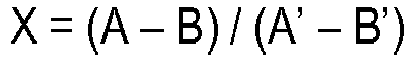 pour comparer (S4) la valeur calculée (X) à une deuxième valeur de seuil, dans lequel il est déterminé que le capillaire est à l'état correctement rempli lorsque la valeur calculée (X) est supérieure ou égale à la deuxième valeur de seuil,pour démarrer automatiquement une mesure de l'échantillon biologique au cas où il est déterminé, à partir de la comparaison (S4), que le capillaire (11, 111) est à l'état correctement rempli, etpour afficher (S5) sur la section d'affichage (2) un affichage recommandant un dépôt supplémentaire de l'échantillon biologique au cas où il est déterminé, à partir de la comparaison (S4), que le capillaire (11, 111) n'est pas à l'état correctement rempli.
 - Système de mesure d'échantillons biologiques, comprenant:un capteur de mesure d'échantillon biologique (3, 103) comprenant un capillaire (11, 111) pour introduire un échantillon biologique dans le capteur, un réactif (10, 110) prévu à l'intérieur du capillaire et une pluralité d'électrodes (8a, 8b, 8c, 108a, 108b, 108c) disposées le long du capillaire (11, 111),un dispositif de mesure d'échantillon biologique, comprenant:une portion de montage (4) sur laquelle est monté le capteur de mesure d'échantillon biologique (3, 103),une section d'application de tension (12, 12a) qui est configurée pour appliquer, à la pluralité d'électrodes (8a, 8b, 8c, 108a, 108b, 108c), de la tension utilisée pour la mesure,une section d'affichage (2) configurée pour afficher de l'information relative à l'échantillon biologique, etune unité de commande (20) qui est configurée pour détecter le degré auquel l'échantillon biologique est introduit dans le capillaire (11, 111), sur la base d'un résultat de sortie mesuré en appliquant aux électrodes (8a, 8b, 8c, 108a, 108b, 108c) une tension de la section d'application de tension (12, 12a),dans lequel la pluralité d'électrodes (8a, 8b, 8c, 108a, 108b, 108c) comprend:une première électrode (8c, 108c) qui, parmi la pluralité d'électrodes (8a, 8b, 8c, 108a, 108b, 108c), est disposée à l'intérieur du capillaire (11, 111) de manière à être la plus éloignée d'un côté d'entrée du capillaire (11, 111),une deuxième électrode (8a, 108a) qui est disposée plus près du côté d'entrée du capillaire (11, 111) que la première électrode (8c, 108c) dans une zone du capillaire (11, 111) où est prévu le réactif (10, 110), etune troisième électrode (8b, 108b) comprenant:une première portion de la troisième électrode (8b, 108b), qui est disposée plus près d'une entrée du capillaire (11, 111) que la deuxième électrode (8a, 108a), etune deuxième portion de la troisième électrode (8b, 108b), qui est disposée entre les première et deuxième électrodes (8c, 108c, 8a, 108a) etl'unité de commande (20) est configurée pour déterminer si le capillaire (11, 111) est dans un état correctement rempli, sur la base d'une fonction liée à la pente d'un graphique montrant le résultat de sortie obtenu en appliquant (S11) de la tension alternativement entre les première et troisième électrodes (8c, 8b, 108c, 108b) et entre les deuxième et première électrodes (8a, 8c, 108a, 108c) respectivement pour une durée spécifique,dans lequel l'unité de commande (20) est configurée:pour commander la section d'application de tension (12, 12a) pour appliquer (S11) une tension spécifique (V1) alternativement entre les première et troisième électrodes (8c, 8b, 108c, 108b) et entre les deuxième et première électrodes (8a, 8c, 108a, 108c) afin de détecter si le capillaire (11, 111) a été rempli de l'échantillon biologique,pour attendre (S2) jusqu'à ce qu'un courant de sortie produit en appliquant la tension (V1) alternativement entre les première et troisième électrodes (8c, 8b, 108c, 108b) et entre les deuxième et première électrodes (8a, 8c, 108a, 108c) atteigne ou dépasse une première valeur de seuil (V2),pour calculer (S13), lorsque le courant de sortie atteint ou dépasse la première valeur de seuil (V2), une valeur (X) en tant que
 pour comparer (S14) la valeur calculée (X) à une deuxième valeur de seuil, dans lequel il est déterminé que le capillaire est à l'état correctement rempli lorsque la valeur calculée (X) est supérieure ou égale à la deuxième valeur de seuil,pour démarrer automatiquement une mesure de l'échantillon biologique au cas où il est déterminé, à partir de la comparaison (S14), que le capillaire (11, 111) est à l'état correctement rempli, etpour afficher (S5) sur la section d'affichage (2) un affichage recommandant un dépôt supplémentaire de l'échantillon biologique au cas où il est déterminé, à partir de la comparaison (S14), que le capillaire (11, 111) n'est pas à l'état correctement rempli.
 - Système de mesure d'échantillons biologiques, comprenant:un capteur de mesure d'échantillon biologique (3, 103) comprenant un capillaire (11, 111) pour introduire un échantillon biologique dans le capteur, un réactif (10, 110) prévu à l'intérieur du capillaire et une pluralité d'électrodes (8a, 8b, 8c, 108a, 108b, 108c) disposées le long du capillaire (11, 111),un dispositif de mesure d'échantillon biologique, comprenant:une portion de montage (4) sur laquelle est monté le capteur de mesure d'échantillon biologique (3, 103),une section d'application de tension (12, 12a) qui est configurée pour appliquer, à la pluralité d'électrodes (8a, 8b, 8c, 108a, 108b, 108c), de la tension utilisée pour la mesure,une section d'affichage (2) configurée pour afficher de l'information relative à l'échantillon biologique, etune unité de commande (20) qui est configurée pour détecter le degré auquel l'échantillon biologique est introduit dans le capillaire (11, 111), sur la base d'un résultat de sortie mesuré en appliquant aux électrodes (8a, 8b, 8c, 108a, 108b, 108c) une tension de la section d'application de tension (12, 12a),dans lequel la pluralité d'électrodes (8a, 8b, 8c, 108a, 108b, 108c) comprend:une première électrode (8c, 108c) qui, parmi la pluralité d'électrodes (8a, 8b, 8c, 108a, 108b, 108c), est disposée à l'intérieur du capillaire (11, 111) de manière à être la plus éloignée d'un côté d'entrée du capillaire (11, 111),une deuxième électrode (8a, 108a) qui est disposée plus près du côté d'entrée du capillaire (11, 111) que la première électrode (8c, 108c) dans une zone du capillaire (11, 111) où est prévu le réactif (10, 110), etune troisième électrode (8b, 108b) comprenant:une première portion de la troisième électrode (8b, 108b), qui est disposée plus près d'une entrée du capillaire (11, 111) que la deuxième électrode (8a, 108a), etune deuxième portion de la troisième électrode (8b, 108b), qui est disposée entre les première et deuxième électrodes (8c, 108c, 8a, 108a) etl'unité de commande (20) est configurée pour déterminer si le capillaire (11, 111) est dans un état correctement rempli, sur la base d'une fonction liée à la pente d'un graphique montrant le résultat de sortie obtenu en appliquant (S21) de la tension entre les première et troisième électrodes (8c, 8b, 108c, 108b),dans lequel l'unité de commande (20) est configurée:pour commander la section d'application de tension (12, 12a) pour appliquer (S21) une tension spécifique (V1) entre les première et troisième électrodes (8a, 8c, 108a, 108c) afin de détecter si le capillaire (11, 111) a été rempli de l'échantillon biologique,pour attendre (S2) jusqu'à ce qu'un courant de sortie produit en appliquant la tension (V1) entre les première et troisième électrodes (8c, 8b, 108c, 108b) atteigne ou dépasse une première valeur de seuil (V2),pour calculer (S23), lorsque le courant de sortie atteint ou dépasse la première valeur de seuil (V2), une valeur (X) en tant que
 pour comparer (S24) la valeur calculée (X) à une deuxième valeur de seuil, dans lequel il est déterminé que le capillaire est à l'état correctement rempli lorsque la valeur calculée (X) est supérieure ou égale à la deuxième valeur de seuil,pour démarrer automatiquement une mesure de l'échantillon biologique au cas où il est déterminé, à partir de la comparaison (S24), que le capillaire (11, 111) est à l'état correctement rempli, etpour afficher (S5) sur la section d'affichage (2) un affichage recommandant un dépôt supplémentaire de l'échantillon biologique au cas où il est déterminé, à partir de la comparaison (S24), que le capillaire (11, 111) n'est pas à l'état correctement rempli.
 - Système de mesure d'échantillon biologique selon l'une quelconque des revendications 1 à 3,
dans lequel l'unité de commande (20) est configurée pour détecter un dépôt supplémentaire de l'échantillon biologique en détectant que la valeur calculée (X) a dépassé une valeur de seuil spécifique après avoir conclu, en tant que résultat de la détection du degré auquel l'échantillon biologique a été introduit, que le capillaire ne contient pas une quantité suffisante de l'échantillon biologique. - Système de mesure d'échantillon biologique selon l'une quelconque des revendications 1 à 4,
dans lequel l'unité de commande (20) est en outre configurée pour afficher (S7) sur la section d'affichage (2) un affichage d'erreur de mesure sur la base du résultat de détection du degré auquel l'échantillon biologique est introduit.
Applications Claiming Priority (2)
| Application Number | Priority Date | Filing Date | Title |
|---|---|---|---|
| JP2011036647 | 2011-02-23 | ||
| PCT/JP2012/001096 WO2012114706A1 (fr) | 2011-02-23 | 2012-02-20 | Dispositif de mesure d'échantillons biologiques |
Publications (3)
| Publication Number | Publication Date |
|---|---|
| EP2679992A1 EP2679992A1 (fr) | 2014-01-01 |
| EP2679992A4 EP2679992A4 (fr) | 2016-05-11 |
| EP2679992B1 true EP2679992B1 (fr) | 2019-10-23 |
Family
ID=46720500
Family Applications (1)
| Application Number | Title | Priority Date | Filing Date |
|---|---|---|---|
| EP12749390.6A Active EP2679992B1 (fr) | 2011-02-23 | 2012-02-20 | Système de mesure d'échantillons biologiques |
Country Status (5)
| Country | Link |
|---|---|
| US (2) | US9213015B2 (fr) |
| EP (1) | EP2679992B1 (fr) |
| JP (1) | JP5728568B2 (fr) |
| CN (1) | CN103348239B (fr) |
| WO (1) | WO2012114706A1 (fr) |
Families Citing this family (3)
| Publication number | Priority date | Publication date | Assignee | Title |
|---|---|---|---|---|
| US9297819B2 (en) * | 2011-07-22 | 2016-03-29 | Sysmex Corporation | Hematology analyzing system and analyzer |
| WO2014057625A1 (fr) * | 2012-10-10 | 2014-04-17 | パナソニックヘルスケア株式会社 | Dispositif de mesure d'informations biologiques |
| WO2018097214A1 (fr) * | 2016-11-25 | 2018-05-31 | パナソニックヘルスケアホールディングス株式会社 | Procédé de mesure de composants d'un échantillon biologique |
Citations (1)
| Publication number | Priority date | Publication date | Assignee | Title |
|---|---|---|---|---|
| EP1746413A2 (fr) * | 2005-07-19 | 2007-01-24 | Hypoguard Limited | Biocapteur électrochimique et procédé de fabrication |
Family Cites Families (25)
| Publication number | Priority date | Publication date | Assignee | Title |
|---|---|---|---|---|
| US7407811B2 (en) | 1997-12-22 | 2008-08-05 | Roche Diagnostics Operations, Inc. | System and method for analyte measurement using AC excitation |
| US7390667B2 (en) | 1997-12-22 | 2008-06-24 | Roche Diagnostics Operations, Inc. | System and method for analyte measurement using AC phase angle measurements |
| US7494816B2 (en) | 1997-12-22 | 2009-02-24 | Roche Diagnostic Operations, Inc. | System and method for determining a temperature during analyte measurement |
| CN102012389B (zh) | 2001-01-17 | 2013-04-10 | 爱科来株式会社 | 使用传感器的定量分析方法和定量分析装置 |
| EP1281955B1 (fr) | 2001-04-16 | 2013-06-05 | Panasonic Corporation | Biodétecteur |
| AU784254B2 (en) | 2001-05-21 | 2006-03-02 | Bayer Corporation | Improved electrochemical sensor |
| US6743635B2 (en) * | 2002-04-25 | 2004-06-01 | Home Diagnostics, Inc. | System and methods for blood glucose sensing |
| US7537684B2 (en) * | 2002-07-25 | 2009-05-26 | Arkray, Inc. | Sample analyzing method and sample analyzing device |
| US7132041B2 (en) | 2003-02-11 | 2006-11-07 | Bayer Healthcare Llc | Methods of determining the concentration of an analyte in a fluid test sample |
| US7597793B2 (en) | 2003-06-20 | 2009-10-06 | Roche Operations Ltd. | System and method for analyte measurement employing maximum dosing time delay |
| US7452457B2 (en) | 2003-06-20 | 2008-11-18 | Roche Diagnostics Operations, Inc. | System and method for analyte measurement using dose sufficiency electrodes |
| US7488601B2 (en) | 2003-06-20 | 2009-02-10 | Roche Diagnostic Operations, Inc. | System and method for determining an abused sensor during analyte measurement |
| KR101108381B1 (ko) * | 2004-04-19 | 2012-01-30 | 파나소닉 주식회사 | 혈액 성분의 측정 방법, 그것에 이용하는 바이오 센서 및측정 장치 |
| US7547382B2 (en) * | 2005-04-15 | 2009-06-16 | Agamatrix, Inc. | Determination of partial fill in electrochemical strips |
| TW200933145A (en) * | 2007-10-31 | 2009-08-01 | Arkray Inc | Analysis tool, analyzer, sample shortage detection method, and sample analysis method |
| US8344733B2 (en) * | 2008-03-27 | 2013-01-01 | Panasonic Corporation | Sample measurement device, sample measurement system and sample measurement method |
| JP2009250806A (ja) * | 2008-04-07 | 2009-10-29 | Panasonic Corp | バイオセンサシステム、センサチップおよび血液試料中の分析物濃度の測定方法 |
| US8551320B2 (en) * | 2008-06-09 | 2013-10-08 | Lifescan, Inc. | System and method for measuring an analyte in a sample |
| CN102265149B (zh) * | 2009-01-30 | 2014-01-15 | 松下电器产业株式会社 | 生物体试料的温度测定方法、生物体试料的浓度测定方法、传感器芯片及生物传感器系统 |
| JP5428617B2 (ja) * | 2009-07-28 | 2014-02-26 | 富士通株式会社 | プロセッサ及び演算処理方法 |
| JP5782044B2 (ja) * | 2009-11-10 | 2015-09-24 | バイエル・ヘルスケア・エルエルシーBayer HealthCareLLC | バイオセンサ用の充填量不足認識システム |
| IL209760A (en) * | 2009-12-11 | 2015-05-31 | Lifescan Scotland Ltd | A system and method for measuring filling is satisfactory |
| JP4840520B2 (ja) * | 2010-04-27 | 2011-12-21 | パナソニック株式会社 | バイオセンサ、バイオセンサ用測定装置及び基質の定量方法 |
| JP4840521B2 (ja) * | 2010-04-27 | 2011-12-21 | パナソニック株式会社 | バイオセンサ、バイオセンサ用測定装置及び基質の定量方法 |
| BR112012031375A2 (pt) * | 2010-06-07 | 2016-10-25 | Bayer Healthcare Llc | sistema de gerenciamento de enchimento abaixo do necessário para um biosensor |
-
2012
- 2012-02-20 US US13/982,747 patent/US9213015B2/en active Active
- 2012-02-20 WO PCT/JP2012/001096 patent/WO2012114706A1/fr active Application Filing
- 2012-02-20 CN CN201280006577.2A patent/CN103348239B/zh active Active
- 2012-02-20 JP JP2013500879A patent/JP5728568B2/ja active Active
- 2012-02-20 EP EP12749390.6A patent/EP2679992B1/fr active Active
-
2015
- 2015-10-30 US US14/927,470 patent/US10241069B2/en active Active
Patent Citations (1)
| Publication number | Priority date | Publication date | Assignee | Title |
|---|---|---|---|---|
| EP1746413A2 (fr) * | 2005-07-19 | 2007-01-24 | Hypoguard Limited | Biocapteur électrochimique et procédé de fabrication |
Also Published As
| Publication number | Publication date |
|---|---|
| WO2012114706A1 (fr) | 2012-08-30 |
| EP2679992A4 (fr) | 2016-05-11 |
| JPWO2012114706A1 (ja) | 2014-07-07 |
| US20160047776A1 (en) | 2016-02-18 |
| EP2679992A1 (fr) | 2014-01-01 |
| US9213015B2 (en) | 2015-12-15 |
| CN103348239A (zh) | 2013-10-09 |
| JP5728568B2 (ja) | 2015-06-03 |
| US10241069B2 (en) | 2019-03-26 |
| CN103348239B (zh) | 2015-09-30 |
| US20130306474A1 (en) | 2013-11-21 |
Similar Documents
| Publication | Publication Date | Title |
|---|---|---|
| US10175194B2 (en) | Underfill management system for a biosensor | |
| KR101289757B1 (ko) | 전기화학적 스트립에서의 부분적인 채워짐의 판별 | |
| EP1411348B1 (fr) | Appareil et dispositif pour analyse | |
| EP2149792B1 (fr) | Procédé d'analyse d'échantillons | |
| US9645104B2 (en) | Capacitance detection in electrochemical assay | |
| RU2594513C1 (ru) | Система и способ для обнаружения использованных и высохших датчиков | |
| US20180196000A1 (en) | Underfill Detection System For A Biosensor | |
| EP2259038A1 (fr) | Procédé de mesure de la température d un environnement, procédé de mesure d échantillon liquide, et dispositif de mesure | |
| EP2539711B1 (fr) | Détection de capacitance en analyse électrochimique | |
| US10473609B2 (en) | Vital information measurement device | |
| US10241069B2 (en) | Biological sample measuring device | |
| US10344312B2 (en) | Blood component measurement device and blood component measurement method | |
| EP2871471B1 (fr) | Appareil et procédé de mesure | |
| WO2014125420A1 (fr) | Système et procédé pour mesurer un analyte dans un échantillon et calculer des concentrations de glucose indépendamment des hématocrites | |
| EP4151993A1 (fr) | Procédé et appareil de mesure | |
| JP2023067185A (ja) | 測定方法及び測定装置 | |
| MXPA06008846A (en) | Electrochemical biosensor |
Legal Events
| Date | Code | Title | Description |
|---|---|---|---|
| PUAI | Public reference made under article 153(3) epc to a published international application that has entered the european phase |
Free format text: ORIGINAL CODE: 0009012 |
|
| 17P | Request for examination filed |
Effective date: 20130923 |
|
| AK | Designated contracting states |
Kind code of ref document: A1 Designated state(s): AL AT BE BG CH CY CZ DE DK EE ES FI FR GB GR HR HU IE IS IT LI LT LU LV MC MK MT NL NO PL PT RO RS SE SI SK SM TR |
|
| RAP1 | Party data changed (applicant data changed or rights of an application transferred) |
Owner name: PANASONIC HEALTHCARE CO., LTD. |
|
| DAX | Request for extension of the european patent (deleted) | ||
| RAP1 | Party data changed (applicant data changed or rights of an application transferred) |
Owner name: PANASONIC HEALTHCARE HOLDINGS CO., LTD. |
|
| RAP1 | Party data changed (applicant data changed or rights of an application transferred) |
Owner name: PANASONIC HEALTHCARE HOLDINGS CO., LTD. |
|
| RA4 | Supplementary search report drawn up and despatched (corrected) |
Effective date: 20160411 |
|
| RIC1 | Information provided on ipc code assigned before grant |
Ipc: G01N 27/416 20060101AFI20160405BHEP Ipc: G01N 27/26 20060101ALI20160405BHEP Ipc: G01N 27/327 20060101ALI20160405BHEP |
|
| RIN1 | Information on inventor provided before grant (corrected) |
Inventor name: HIRONAKA, SHOUKO Inventor name: YOSHIOKA, ERIKO Inventor name: SHINNO, TEPPEI |
|
| STAA | Information on the status of an ep patent application or granted ep patent |
Free format text: STATUS: EXAMINATION IS IN PROGRESS |
|
| 17Q | First examination report despatched |
Effective date: 20170714 |
|
| RAP1 | Party data changed (applicant data changed or rights of an application transferred) |
Owner name: PHC HOLDINGS CORPORATION |
|
| REG | Reference to a national code |
Ref country code: DE Ref legal event code: R079 Ref document number: 602012065087 Country of ref document: DE Free format text: PREVIOUS MAIN CLASS: G01N0027416000 Ipc: G01N0027327000 |
|
| RIC1 | Information provided on ipc code assigned before grant |
Ipc: G01N 33/49 20060101ALI20190326BHEP Ipc: G01N 27/327 20060101AFI20190326BHEP |
|
| GRAP | Despatch of communication of intention to grant a patent |
Free format text: ORIGINAL CODE: EPIDOSNIGR1 |
|
| STAA | Information on the status of an ep patent application or granted ep patent |
Free format text: STATUS: GRANT OF PATENT IS INTENDED |
|
| INTG | Intention to grant announced |
Effective date: 20190520 |
|
| GRAS | Grant fee paid |
Free format text: ORIGINAL CODE: EPIDOSNIGR3 |
|
| GRAA | (expected) grant |
Free format text: ORIGINAL CODE: 0009210 |
|
| STAA | Information on the status of an ep patent application or granted ep patent |
Free format text: STATUS: THE PATENT HAS BEEN GRANTED |
|
| AK | Designated contracting states |
Kind code of ref document: B1 Designated state(s): AL AT BE BG CH CY CZ DE DK EE ES FI FR GB GR HR HU IE IS IT LI LT LU LV MC MK MT NL NO PL PT RO RS SE SI SK SM TR |
|
| REG | Reference to a national code |
Ref country code: GB Ref legal event code: FG4D |
|
| RIN1 | Information on inventor provided before grant (corrected) |
Inventor name: SHINNO, TEPPEI Inventor name: HIRONAKA, SHOUKO Inventor name: YOSHIOKA, ERIKO |
|
| REG | Reference to a national code |
Ref country code: CH Ref legal event code: EP |
|
| REG | Reference to a national code |
Ref country code: IE Ref legal event code: FG4D |
|
| REG | Reference to a national code |
Ref country code: DE Ref legal event code: R096 Ref document number: 602012065087 Country of ref document: DE |
|
| REG | Reference to a national code |
Ref country code: AT Ref legal event code: REF Ref document number: 1194210 Country of ref document: AT Kind code of ref document: T Effective date: 20191115 |
|
| REG | Reference to a national code |
Ref country code: NL Ref legal event code: MP Effective date: 20191023 |
|
| REG | Reference to a national code |
Ref country code: LT Ref legal event code: MG4D |
|
| PG25 | Lapsed in a contracting state [announced via postgrant information from national office to epo] |
Ref country code: GR Free format text: LAPSE BECAUSE OF FAILURE TO SUBMIT A TRANSLATION OF THE DESCRIPTION OR TO PAY THE FEE WITHIN THE PRESCRIBED TIME-LIMIT Effective date: 20200124 Ref country code: LT Free format text: LAPSE BECAUSE OF FAILURE TO SUBMIT A TRANSLATION OF THE DESCRIPTION OR TO PAY THE FEE WITHIN THE PRESCRIBED TIME-LIMIT Effective date: 20191023 Ref country code: PL Free format text: LAPSE BECAUSE OF FAILURE TO SUBMIT A TRANSLATION OF THE DESCRIPTION OR TO PAY THE FEE WITHIN THE PRESCRIBED TIME-LIMIT Effective date: 20191023 Ref country code: NO Free format text: LAPSE BECAUSE OF FAILURE TO SUBMIT A TRANSLATION OF THE DESCRIPTION OR TO PAY THE FEE WITHIN THE PRESCRIBED TIME-LIMIT Effective date: 20200123 Ref country code: SE Free format text: LAPSE BECAUSE OF FAILURE TO SUBMIT A TRANSLATION OF THE DESCRIPTION OR TO PAY THE FEE WITHIN THE PRESCRIBED TIME-LIMIT Effective date: 20191023 Ref country code: LV Free format text: LAPSE BECAUSE OF FAILURE TO SUBMIT A TRANSLATION OF THE DESCRIPTION OR TO PAY THE FEE WITHIN THE PRESCRIBED TIME-LIMIT Effective date: 20191023 Ref country code: PT Free format text: LAPSE BECAUSE OF FAILURE TO SUBMIT A TRANSLATION OF THE DESCRIPTION OR TO PAY THE FEE WITHIN THE PRESCRIBED TIME-LIMIT Effective date: 20200224 Ref country code: BG Free format text: LAPSE BECAUSE OF FAILURE TO SUBMIT A TRANSLATION OF THE DESCRIPTION OR TO PAY THE FEE WITHIN THE PRESCRIBED TIME-LIMIT Effective date: 20200123 Ref country code: FI Free format text: LAPSE BECAUSE OF FAILURE TO SUBMIT A TRANSLATION OF THE DESCRIPTION OR TO PAY THE FEE WITHIN THE PRESCRIBED TIME-LIMIT Effective date: 20191023 Ref country code: NL Free format text: LAPSE BECAUSE OF FAILURE TO SUBMIT A TRANSLATION OF THE DESCRIPTION OR TO PAY THE FEE WITHIN THE PRESCRIBED TIME-LIMIT Effective date: 20191023 Ref country code: ES Free format text: LAPSE BECAUSE OF FAILURE TO SUBMIT A TRANSLATION OF THE DESCRIPTION OR TO PAY THE FEE WITHIN THE PRESCRIBED TIME-LIMIT Effective date: 20191023 |
|
| PG25 | Lapsed in a contracting state [announced via postgrant information from national office to epo] |
Ref country code: HR Free format text: LAPSE BECAUSE OF FAILURE TO SUBMIT A TRANSLATION OF THE DESCRIPTION OR TO PAY THE FEE WITHIN THE PRESCRIBED TIME-LIMIT Effective date: 20191023 Ref country code: RS Free format text: LAPSE BECAUSE OF FAILURE TO SUBMIT A TRANSLATION OF THE DESCRIPTION OR TO PAY THE FEE WITHIN THE PRESCRIBED TIME-LIMIT Effective date: 20191023 Ref country code: IS Free format text: LAPSE BECAUSE OF FAILURE TO SUBMIT A TRANSLATION OF THE DESCRIPTION OR TO PAY THE FEE WITHIN THE PRESCRIBED TIME-LIMIT Effective date: 20200224 |
|
| PG25 | Lapsed in a contracting state [announced via postgrant information from national office to epo] |
Ref country code: AL Free format text: LAPSE BECAUSE OF FAILURE TO SUBMIT A TRANSLATION OF THE DESCRIPTION OR TO PAY THE FEE WITHIN THE PRESCRIBED TIME-LIMIT Effective date: 20191023 |
|
| REG | Reference to a national code |
Ref country code: DE Ref legal event code: R097 Ref document number: 602012065087 Country of ref document: DE |
|
| PG2D | Information on lapse in contracting state deleted |
Ref country code: IS |
|
| PG25 | Lapsed in a contracting state [announced via postgrant information from national office to epo] |
Ref country code: RO Free format text: LAPSE BECAUSE OF FAILURE TO SUBMIT A TRANSLATION OF THE DESCRIPTION OR TO PAY THE FEE WITHIN THE PRESCRIBED TIME-LIMIT Effective date: 20191023 Ref country code: CZ Free format text: LAPSE BECAUSE OF FAILURE TO SUBMIT A TRANSLATION OF THE DESCRIPTION OR TO PAY THE FEE WITHIN THE PRESCRIBED TIME-LIMIT Effective date: 20191023 Ref country code: EE Free format text: LAPSE BECAUSE OF FAILURE TO SUBMIT A TRANSLATION OF THE DESCRIPTION OR TO PAY THE FEE WITHIN THE PRESCRIBED TIME-LIMIT Effective date: 20191023 Ref country code: DK Free format text: LAPSE BECAUSE OF FAILURE TO SUBMIT A TRANSLATION OF THE DESCRIPTION OR TO PAY THE FEE WITHIN THE PRESCRIBED TIME-LIMIT Effective date: 20191023 Ref country code: IS Free format text: LAPSE BECAUSE OF FAILURE TO SUBMIT A TRANSLATION OF THE DESCRIPTION OR TO PAY THE FEE WITHIN THE PRESCRIBED TIME-LIMIT Effective date: 20200223 |
|
| REG | Reference to a national code |
Ref country code: AT Ref legal event code: MK05 Ref document number: 1194210 Country of ref document: AT Kind code of ref document: T Effective date: 20191023 |
|
| PLBE | No opposition filed within time limit |
Free format text: ORIGINAL CODE: 0009261 |
|
| STAA | Information on the status of an ep patent application or granted ep patent |
Free format text: STATUS: NO OPPOSITION FILED WITHIN TIME LIMIT |
|
| PG25 | Lapsed in a contracting state [announced via postgrant information from national office to epo] |
Ref country code: IT Free format text: LAPSE BECAUSE OF FAILURE TO SUBMIT A TRANSLATION OF THE DESCRIPTION OR TO PAY THE FEE WITHIN THE PRESCRIBED TIME-LIMIT Effective date: 20191023 Ref country code: SM Free format text: LAPSE BECAUSE OF FAILURE TO SUBMIT A TRANSLATION OF THE DESCRIPTION OR TO PAY THE FEE WITHIN THE PRESCRIBED TIME-LIMIT Effective date: 20191023 Ref country code: SK Free format text: LAPSE BECAUSE OF FAILURE TO SUBMIT A TRANSLATION OF THE DESCRIPTION OR TO PAY THE FEE WITHIN THE PRESCRIBED TIME-LIMIT Effective date: 20191023 |
|
| 26N | No opposition filed |
Effective date: 20200724 |
|
| REG | Reference to a national code |
Ref country code: CH Ref legal event code: PL |
|
| GBPC | Gb: european patent ceased through non-payment of renewal fee |
Effective date: 20200220 |
|
| REG | Reference to a national code |
Ref country code: BE Ref legal event code: MM Effective date: 20200229 |
|
| PG25 | Lapsed in a contracting state [announced via postgrant information from national office to epo] |
Ref country code: LU Free format text: LAPSE BECAUSE OF NON-PAYMENT OF DUE FEES Effective date: 20200220 Ref country code: MC Free format text: LAPSE BECAUSE OF FAILURE TO SUBMIT A TRANSLATION OF THE DESCRIPTION OR TO PAY THE FEE WITHIN THE PRESCRIBED TIME-LIMIT Effective date: 20191023 |
|
| PG25 | Lapsed in a contracting state [announced via postgrant information from national office to epo] |
Ref country code: AT Free format text: LAPSE BECAUSE OF FAILURE TO SUBMIT A TRANSLATION OF THE DESCRIPTION OR TO PAY THE FEE WITHIN THE PRESCRIBED TIME-LIMIT Effective date: 20191023 Ref country code: CH Free format text: LAPSE BECAUSE OF NON-PAYMENT OF DUE FEES Effective date: 20200229 Ref country code: SI Free format text: LAPSE BECAUSE OF FAILURE TO SUBMIT A TRANSLATION OF THE DESCRIPTION OR TO PAY THE FEE WITHIN THE PRESCRIBED TIME-LIMIT Effective date: 20191023 Ref country code: LI Free format text: LAPSE BECAUSE OF NON-PAYMENT OF DUE FEES Effective date: 20200229 |
|
| PG25 | Lapsed in a contracting state [announced via postgrant information from national office to epo] |
Ref country code: IE Free format text: LAPSE BECAUSE OF NON-PAYMENT OF DUE FEES Effective date: 20200220 Ref country code: FR Free format text: LAPSE BECAUSE OF NON-PAYMENT OF DUE FEES Effective date: 20200229 Ref country code: GB Free format text: LAPSE BECAUSE OF NON-PAYMENT OF DUE FEES Effective date: 20200220 |
|
| PG25 | Lapsed in a contracting state [announced via postgrant information from national office to epo] |
Ref country code: BE Free format text: LAPSE BECAUSE OF NON-PAYMENT OF DUE FEES Effective date: 20200229 |
|
| PG25 | Lapsed in a contracting state [announced via postgrant information from national office to epo] |
Ref country code: TR Free format text: LAPSE BECAUSE OF FAILURE TO SUBMIT A TRANSLATION OF THE DESCRIPTION OR TO PAY THE FEE WITHIN THE PRESCRIBED TIME-LIMIT Effective date: 20191023 Ref country code: MT Free format text: LAPSE BECAUSE OF FAILURE TO SUBMIT A TRANSLATION OF THE DESCRIPTION OR TO PAY THE FEE WITHIN THE PRESCRIBED TIME-LIMIT Effective date: 20191023 Ref country code: CY Free format text: LAPSE BECAUSE OF FAILURE TO SUBMIT A TRANSLATION OF THE DESCRIPTION OR TO PAY THE FEE WITHIN THE PRESCRIBED TIME-LIMIT Effective date: 20191023 |
|
| PG25 | Lapsed in a contracting state [announced via postgrant information from national office to epo] |
Ref country code: MK Free format text: LAPSE BECAUSE OF FAILURE TO SUBMIT A TRANSLATION OF THE DESCRIPTION OR TO PAY THE FEE WITHIN THE PRESCRIBED TIME-LIMIT Effective date: 20191023 |
|
| PGFP | Annual fee paid to national office [announced via postgrant information from national office to epo] |
Ref country code: DE Payment date: 20230223 Year of fee payment: 12 |