EP2679906A2 - Verfahren zur Wartung einer Brennkammerkappenanordnung für eine Turbine - Google Patents
Verfahren zur Wartung einer Brennkammerkappenanordnung für eine Turbine Download PDFInfo
- Publication number
- EP2679906A2 EP2679906A2 EP13173601.9A EP13173601A EP2679906A2 EP 2679906 A2 EP2679906 A2 EP 2679906A2 EP 13173601 A EP13173601 A EP 13173601A EP 2679906 A2 EP2679906 A2 EP 2679906A2
- Authority
- EP
- European Patent Office
- Prior art keywords
- center ring
- cap assembly
- vanes
- replacement
- turbine
- Prior art date
- Legal status (The legal status is an assumption and is not a legal conclusion. Google has not performed a legal analysis and makes no representation as to the accuracy of the status listed.)
- Withdrawn
Links
Images



Classifications
-
- F—MECHANICAL ENGINEERING; LIGHTING; HEATING; WEAPONS; BLASTING
- F23—COMBUSTION APPARATUS; COMBUSTION PROCESSES
- F23R—GENERATING COMBUSTION PRODUCTS OF HIGH PRESSURE OR HIGH VELOCITY, e.g. GAS-TURBINE COMBUSTION CHAMBERS
- F23R3/00—Continuous combustion chambers using liquid or gaseous fuel
-
- B—PERFORMING OPERATIONS; TRANSPORTING
- B23—MACHINE TOOLS; METAL-WORKING NOT OTHERWISE PROVIDED FOR
- B23K—SOLDERING OR UNSOLDERING; WELDING; CLADDING OR PLATING BY SOLDERING OR WELDING; CUTTING BY APPLYING HEAT LOCALLY, e.g. FLAME CUTTING; WORKING BY LASER BEAM
- B23K1/00—Soldering, e.g. brazing, or unsoldering
- B23K1/0008—Soldering, e.g. brazing, or unsoldering specially adapted for particular articles or work
- B23K1/0018—Brazing of turbine parts
-
- B—PERFORMING OPERATIONS; TRANSPORTING
- B23—MACHINE TOOLS; METAL-WORKING NOT OTHERWISE PROVIDED FOR
- B23K—SOLDERING OR UNSOLDERING; WELDING; CLADDING OR PLATING BY SOLDERING OR WELDING; CUTTING BY APPLYING HEAT LOCALLY, e.g. FLAME CUTTING; WORKING BY LASER BEAM
- B23K26/00—Working by laser beam, e.g. welding, cutting or boring
- B23K26/36—Removing material
-
- B—PERFORMING OPERATIONS; TRANSPORTING
- B23—MACHINE TOOLS; METAL-WORKING NOT OTHERWISE PROVIDED FOR
- B23P—METAL-WORKING NOT OTHERWISE PROVIDED FOR; COMBINED OPERATIONS; UNIVERSAL MACHINE TOOLS
- B23P6/00—Restoring or reconditioning objects
- B23P6/002—Repairing turbine components, e.g. moving or stationary blades, rotors
-
- B—PERFORMING OPERATIONS; TRANSPORTING
- B23—MACHINE TOOLS; METAL-WORKING NOT OTHERWISE PROVIDED FOR
- B23P—METAL-WORKING NOT OTHERWISE PROVIDED FOR; COMBINED OPERATIONS; UNIVERSAL MACHINE TOOLS
- B23P2700/00—Indexing scheme relating to the articles being treated, e.g. manufactured, repaired, assembled, connected or other operations covered in the subgroups
- B23P2700/13—Parts of turbine combustion chambers
-
- F—MECHANICAL ENGINEERING; LIGHTING; HEATING; WEAPONS; BLASTING
- F23—COMBUSTION APPARATUS; COMBUSTION PROCESSES
- F23R—GENERATING COMBUSTION PRODUCTS OF HIGH PRESSURE OR HIGH VELOCITY, e.g. GAS-TURBINE COMBUSTION CHAMBERS
- F23R2900/00—Special features of, or arrangements for continuous combustion chambers; Combustion processes therefor
- F23R2900/00019—Repairing or maintaining combustion chamber liners or subparts
-
- Y—GENERAL TAGGING OF NEW TECHNOLOGICAL DEVELOPMENTS; GENERAL TAGGING OF CROSS-SECTIONAL TECHNOLOGIES SPANNING OVER SEVERAL SECTIONS OF THE IPC; TECHNICAL SUBJECTS COVERED BY FORMER USPC CROSS-REFERENCE ART COLLECTIONS [XRACs] AND DIGESTS
- Y10—TECHNICAL SUBJECTS COVERED BY FORMER USPC
- Y10T—TECHNICAL SUBJECTS COVERED BY FORMER US CLASSIFICATION
- Y10T29/00—Metal working
- Y10T29/49—Method of mechanical manufacture
- Y10T29/49229—Prime mover or fluid pump making
- Y10T29/49231—I.C. [internal combustion] engine making
- Y10T29/49233—Repairing, converting, servicing or salvaging
Definitions
- the subject matter disclosed herein relates to turbine engines. More particularly, the subject matter relates to servicing a cap assembly of a turbine engine.
- a combustor converts chemical energy of a fuel or an air-fuel mixture into thermal energy.
- the thermal energy is conveyed by a fluid, often air from a compressor, to a turbine where the thermal energy is converted to mechanical energy.
- These fluids flow downstream to one or more turbines that extract energy therefrom to produce the mechanical energy output as well as power to drive the compressor.
- turbine parts may experience wear and degradation due to extreme conditions caused by flow of heated fluid within the turbine engine.
- combustion dynamics and combustion temperatures in selected locations may lead to thermal stress and wear of parts in the assemblies.
- repairing or replacing a single part of the assembly can lead to replacement of an entire assembly. Replacing an entire assembly due to a defect in a single part within the assembly is a costly and time consuming service process.
- a method for servicing a combustor cap assembly of a turbine includes determining a defect is present in a center ring of the cap assembly, the center ring being disposed within a plurality of vanes, removing the center ring from the cap assembly. The method also includes placing a replacement center ring in the cap assembly, wherein dimensions of the replacement center ring are substantially the same as the center ring that has been removed and brazing the replacement center ring to the plurality of vanes.
- a method for servicing a combustor of a turbine the combustor including a cap assembly.
- the method includes determining a defect is present in a center ring of the cap assembly, the center ring being disposed within a plurality of vanes, removing the center ring from the cap assembly by a process that does not substantially load the plurality of vanes, thereby enabling the plurality of vanes to remain structurally intact during the removing, placing a replacement center ring in the cap assembly, wherein dimensions of the replacement center ring are substantially the same as the center ring that has been removed and coupling the replacement center ring to the plurality of vanes.
- FIG. 1 is a schematic diagram of an embodiment of a gas turbine system 100.
- the system 100 includes a compressor 102, a combustor 104, a turbine 106, a shaft 108 and a fuel nozzle 110.
- the system 100 may include a plurality of compressors 102, combustors 104, turbines 106, shafts 108 and fuel nozzles 110.
- the compressor 102 and turbine 106 are coupled by the shaft 108.
- the shaft 108 may be a single shaft or a plurality of shaft segments coupled together to form shaft 108.
- the system 100 may also include a plurality of compressors 102 and turbines 106 disposed about a turbine axis (not shown).
- the combustor 104 uses liquid and/or gas fuel, such as natural gas or a hydrogen rich synthetic gas, to run the turbine engine.
- fuel nozzles 110 are in fluid communication with a fuel supply 112 and pressurized air from the compressor 102.
- the fuel nozzles 110 create an air-fuel mix, and discharge the air-fuel mix into the combustor 104, thereby causing a combustion that creates a hot pressurized exhaust gas.
- the combustor 104 directs the hot pressurized exhaust gas through a transition piece into a turbine nozzle (or "stage one nozzle"), causing turbine 106 rotation as the gas exits the nozzle or vane and gets directed to the turbine bucket or blade.
- turbine 106 causes the shaft 108 to rotate, thereby compressing the air as it flows into the compressor 102.
- combustion dynamics and associated temperatures can lead to thermal distress of components, such as components in the combustor 104 used for fuel and air distribution.
- wear and thermal degradation of combustor 104 components leads to servicing and/or replacement of the components. Methods and systems that may be utilized for servicing a turbine component are discussed in detail below with reference to FIGS. 2-6 .
- downstream and upstream are terms that indicate a direction relative to the flow of working fluid through the turbine.
- downstream refers to a direction that generally corresponds to the direction of the flow of working fluid
- upstream generally refers to the direction that is opposite of the direction of flow of working fluid.
- radial refers to movement or position perpendicular to an axis or center line. It may be useful to describe parts that are at differing radial positions with regard to an axis. In this case, if a first component resides closer to the axis than a second component, it may be stated herein that the first component is "radially inward" of the second component.
- first component resides further from the axis than the second component, it can be stated herein that the first component is “radially outward” or “outboard” of the second component.
- axial refers to movement or position parallel to an axis.
- circumferential refers to movement or position around an axis.
- FIG. 2 is a sectional side view of an exemplary combustor cap assembly 202, where the section is formed by a plane that runs through an axis 208.
- the combustor cap assembly 202 is disposed in a turbine combustor, such as combustor 104.
- the cap assembly 202 includes a center stack 210 where a center ring 212 and vanes 214 are disposed in an annulus 222 of the center stack 210.
- the cap assembly 202 also includes fuel nozzles 216 and 218 disposed about the center stack 210.
- the center stack 210 comprises a plurality of components that are coupled at joints from a base to an end 220, including joints 224, by a suitable process, such as brazing, welding or cladding.
- the center ring 212 is configured to receive a center fuel nozzle (not shown).
- the fuel nozzle supplies fuel to mix with air that swirls as it flows through vanes 214, leading to combustion of the mixture downstream of the vanes 214 and center ring 212.
- the center ring 212 is exposed to combustion dynamics and thermal stress. In some cases, the wear causes formation of a defect in the center ring 212, where the center ring 212 requires servicing to ensure proper performance of the combustor 200.
- the cap assembly 202 is placed on a servicing fixture where the entire center ring 212 is removed from the cap assembly 202 while the rest of the cap assembly remains assembled.
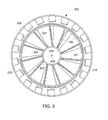
- FIG. 3 is a top view of the center stack 210 portion of the cap assembly 202 shown in FIG. 2 .
- the vanes 214 are coupled to an inner burner tube 301 and center ring 212 via couplings 300 and 302, respectively, where the coupling are formed by a suitable durable method, such as brazing, welding or cladding.
- a suitable durable method such as brazing, welding or cladding.
- the center ring 212 with the defect is removed by a suitable process, such as electrical discharge machining (EDM), high speed milling, laser removal or waterjetting.
- EDM electrical discharge machining
- the center ring 212 is removed by high speed milling with a slow feed rate or by EDM, where the vanes 214 are substantially not loaded and retain their geometry during the removal process.
- the loading of the vanes 214 during a removal process may alter a geometry of the vanes and adversely affect fuel-air mixing and turbine efficiency.
- FIG. 4 is a top view of the center stack 210 portion of the cap assembly 202 shown in FIGS. 2 and 3 installed on a fixture 400 for servicing.
- the fixture 400 provides precise positioning of the cap assembly 202 for removal of the center ring 212 by a selected process.
- the fixture 400 includes a base 402 and supports 404.
- the supports 404 each include alignment or orienting features configured to be placed in orienting holes 406 in the cap assembly 202 to provide precise positioning of the assembly during servicing.
- the orienting features and orienting holes 406 enable the removal tool to find true center of the cap assembly 202 and center ring 212, thereby enabling precise removal of the ring without structurally impacting the vanes 214.
- the fixture 400 is coupled to a suitable apparatus (not shown), such as an EDM machine, configured to precisely remove the center ring 212 after the cap assembly 202 is positioned in the fixture 400.
- FIG. 5 is a side sectional view of the cap assembly 202 with a replacement center ring 500 on a fixture 502 positioned within the cap assembly 202.
- the fixture 502 includes a base 504, elongated support 506 and ring platform 508, where the ring platform 508 positions the replacement center ring 500 for coupling to the vanes 214.
- the fixture 502 precisely positions the replacement center ring 500 relative to the vanes 214 and cap assembly 202, thereby enabling the replacement center ring 500 to be coupled to the vanes 214.
- the replacement center ring 500 is substantially identical in dimension and geometry to the original equipment center ring, thus providing the replacement center ring configured to operate with the assembly without substantial modification after installation.
- the replacement center ring 500 is positioned in the cap assembly 202 and coupled to vanes 214 by a brazing process, where the replacement center ring 500 is not manually machined or modified after being coupled to the vanes 214. Accordingly, the servicing process has reduced manual steps as compared to other processes, thus reducing repair time and the occurrence of defects after repair. Further, the servicing process uses a coupling method, such as brazing, to couple the center ring 500 to the vanes 214 that does not affect joints and couplings in other portions of the cap assembly 202, such as joints 224.
- a coupling method such as brazing
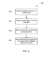
- FIG. 6 is a flow chart 600 of exemplary steps that may be included in a servicing process for a cap assembly, such as cap assembly 202.
- the depicted blocks may be part of or in addition to another process and/or may be performed in any suitable order to provide a serviced and operational cap assembly.
- a determination is made that a defect is present in a center ring of a cap assembly.
- the defect is a crack or worn portion of an inner sleeve surface of the center ring.
- the center ring is removed from the cap assembly by a suitable method, such as EDM, that has reduced loading of vanes coupled to the center ring.
- a fixture such as the fixture 400, may be used to position the cap assembly to enable precise removal of the center ring while enabling the vanes to remain structurally intact. Further, in embodiments, the removal of the center ring does not require disassembly of the cap assembly, thus simplifying the servicing process. In an embodiment, remnants of the removed center ring are removed by a process, such as de-burring.
- a replacement center ring is positioned in the cap assembly, where the replacement center ring has substantially the same dimensions and geometry as the original equipment center ring used during production of the turbine engine. In an embodiment, the replacement center ring is positioned in the cap assembly by a fixture, such as fixture 502.
- the replacement center ring is coupled to the vanes by a suitable method to provide a durable bond, such as brazing.
- the brazing process uses a suitable brazing material, such as a nickel alloy braze paste.
- the braze paste may comprise a nickel alloy compound including but not limited to, AMDRY 103, AMDRY 915 or AMDRY 773.
- the braze paste material is applied to each joint between the vanes and center ring and is then cycled through various heating stages to cure the coupling.
- the assembly may be heated to about 1100 to 1300 Fahrenheit (F) for a first period of time, then heated to about 1850 to 2000 F for a second period of time, then heated to about 2060 to about 2160 F for a third period of time and finally cooled to finish the brazing process.
- F Fahrenheit
- the first, second and third periods of time are all the same. In other embodiments, the first, second and third periods of time are different.
Landscapes
- Engineering & Computer Science (AREA)
- Mechanical Engineering (AREA)
- Chemical & Material Sciences (AREA)
- Combustion & Propulsion (AREA)
- General Engineering & Computer Science (AREA)
- Physics & Mathematics (AREA)
- Optics & Photonics (AREA)
- Plasma & Fusion (AREA)
- Turbine Rotor Nozzle Sealing (AREA)
- Laser Beam Processing (AREA)
Applications Claiming Priority (1)
| Application Number | Priority Date | Filing Date | Title |
|---|---|---|---|
| US13/535,897 US9249976B2 (en) | 2012-06-28 | 2012-06-28 | Method for servicing a combustor cap assembly for a turbine |
Publications (2)
| Publication Number | Publication Date |
|---|---|
| EP2679906A2 true EP2679906A2 (de) | 2014-01-01 |
| EP2679906A3 EP2679906A3 (de) | 2017-12-27 |
Family
ID=48746275
Family Applications (1)
| Application Number | Title | Priority Date | Filing Date |
|---|---|---|---|
| EP13173601.9A Withdrawn EP2679906A3 (de) | 2012-06-28 | 2013-06-25 | Verfahren zur Wartung einer Brennkammerkappenanordnung für eine Turbine |
Country Status (3)
| Country | Link |
|---|---|
| US (1) | US9249976B2 (de) |
| EP (1) | EP2679906A3 (de) |
| JP (1) | JP6159168B2 (de) |
Families Citing this family (2)
| Publication number | Priority date | Publication date | Assignee | Title |
|---|---|---|---|---|
| US9278386B1 (en) | 2014-09-04 | 2016-03-08 | General Electric Company | Hole reducing tool |
| DE102017212575A1 (de) * | 2017-07-21 | 2019-01-24 | Siemens Aktiengesellschaft | Verfahren zur Erhöhung der Leistung einer Gasturbine |
Family Cites Families (17)
| Publication number | Priority date | Publication date | Assignee | Title |
|---|---|---|---|---|
| DE3942271A1 (de) * | 1989-12-21 | 1991-07-04 | Mtu Maintenance Gmbh | Verfahren zur reparatur eines flammrohres |
| EP0564181B1 (de) | 1992-03-30 | 1996-11-20 | General Electric Company | Konstruktion eines Brennkammerdomes |
| US5329772A (en) * | 1992-12-09 | 1994-07-19 | General Electric Company | Cast slot-cooled single nozzle combustion liner cap |
| US5430935A (en) * | 1993-07-14 | 1995-07-11 | Yaworsky; Chester E. | Method for repairing a combustion chamber assembly |
| US6112971A (en) * | 1999-05-12 | 2000-09-05 | General Electric Co. | Multi-nozzle combustion end cover vacuum brazing process |
| US6414458B1 (en) | 2000-12-19 | 2002-07-02 | General Electric Company | Apparatus for robotically inspecting gas turbine combustion components |
| US6532840B2 (en) | 2000-12-19 | 2003-03-18 | General Electric Company | Methods for robotically inspecting gas turbine combustion components |
| JP3915423B2 (ja) * | 2001-03-29 | 2007-05-16 | 株式会社日立製作所 | ガスタービン燃焼器ライナー構造とその補修方法 |
| US6581285B2 (en) * | 2001-06-11 | 2003-06-24 | General Electric Co. | Methods for replacing nuggeted combustor liner panels |
| US6655027B2 (en) * | 2002-01-15 | 2003-12-02 | General Electric Company | Methods for assembling gas turbine engine combustors |
| US6782620B2 (en) * | 2003-01-28 | 2004-08-31 | General Electric Company | Methods for replacing a portion of a combustor dome assembly |
| US7662091B2 (en) | 2004-12-30 | 2010-02-16 | General Electric Company | Flexible borescope assembly for inspecting internal turbine components at elevated temperatures |
| US20070119052A1 (en) * | 2005-11-28 | 2007-05-31 | General Electric Company | Combustor dome repair method |
| US8020385B2 (en) * | 2008-07-28 | 2011-09-20 | General Electric Company | Centerbody cap for a turbomachine combustor and method |
| US8356409B2 (en) * | 2007-11-01 | 2013-01-22 | United Technologies Corporation | Repair method for gas turbine engine components |
| JP5010521B2 (ja) * | 2008-03-28 | 2012-08-29 | 三菱重工業株式会社 | 燃焼器尾筒案内治具及びガスタービンの燃焼器の取り外し方法、並びに製造方法 |
| US7918433B2 (en) | 2008-06-25 | 2011-04-05 | General Electric Company | Transition piece mounting bracket and related method |
-
2012
- 2012-06-28 US US13/535,897 patent/US9249976B2/en active Active
-
2013
- 2013-06-25 EP EP13173601.9A patent/EP2679906A3/de not_active Withdrawn
- 2013-06-25 JP JP2013132196A patent/JP6159168B2/ja not_active Expired - Fee Related
Non-Patent Citations (1)
| Title |
|---|
| None |
Also Published As
| Publication number | Publication date |
|---|---|
| JP2014009691A (ja) | 2014-01-20 |
| US20140000111A1 (en) | 2014-01-02 |
| JP6159168B2 (ja) | 2017-07-05 |
| EP2679906A3 (de) | 2017-12-27 |
| US9249976B2 (en) | 2016-02-02 |
Similar Documents
| Publication | Publication Date | Title |
|---|---|---|
| US10213883B2 (en) | System and method for in situ repair of gas turbine engine casing clearance | |
| US11225869B2 (en) | In situ gas turbine prevention of crack growth progression | |
| US20090271984A1 (en) | Method for repairing a gas turbine engine component | |
| US9567860B2 (en) | Fixture for an airfoil shroud and method for modifying an airfoil shroud | |
| US9694440B2 (en) | Support collar geometry for linear friction welding | |
| US9995487B2 (en) | Method for repairing fuel nozzle guides for gas turbine engine combustors using cold metal transfer weld technology | |
| EP2735704A2 (de) | Verfahren zur Modifizierung eines Schaufeldeckbandes und Schaufel | |
| US10125611B2 (en) | System and method for in situ repair of turbine blades of gas turbine engines | |
| CA2623675C (en) | Turbine nozzle segment and repair method | |
| EP2612992A2 (de) | Turbine und Verfahren zur Abscheidung von Partikeln aus einer Flüssigkeit | |
| EP3203017B1 (de) | Verfahren zum aufhalten eines risses in einer gasturbinentriebwerkskomponente zur durchführung von in-situ-reparaturen | |
| EP3203019B1 (de) | Verfahren zum anfügen von material an einem oberflächenbereich einer gasturbinentriebwerkskomponente | |
| US9249976B2 (en) | Method for servicing a combustor cap assembly for a turbine | |
| US10544676B2 (en) | Situ gas turbine prevention of crack growth progression | |
| US20080080971A1 (en) | Labyrinth seal repair | |
| CA2826488C (en) | Gas generator case repair | |
| US20160362988A1 (en) | Method for modifying an airfoil shroud and airfoil | |
| JP7604198B2 (ja) | 改良されたパッチリングおよび使用方法 | |
| EP4513088A1 (de) | Verfahren zur reparatur von rohren in gebündelten rohrbrennstoffinjektoren | |
| US20140147284A1 (en) | Method for modifying an airfoil shroud | |
| US11028719B2 (en) | Brush seal repair method | |
| EP3163015A1 (de) | Leistungsdüsenreparatur mit installierter kühl-hardware |
Legal Events
| Date | Code | Title | Description |
|---|---|---|---|
| PUAI | Public reference made under article 153(3) epc to a published international application that has entered the european phase |
Free format text: ORIGINAL CODE: 0009012 |
|
| AK | Designated contracting states |
Kind code of ref document: A2 Designated state(s): AL AT BE BG CH CY CZ DE DK EE ES FI FR GB GR HR HU IE IS IT LI LT LU LV MC MK MT NL NO PL PT RO RS SE SI SK SM TR |
|
| AX | Request for extension of the european patent |
Extension state: BA ME |
|
| PUAL | Search report despatched |
Free format text: ORIGINAL CODE: 0009013 |
|
| AK | Designated contracting states |
Kind code of ref document: A3 Designated state(s): AL AT BE BG CH CY CZ DE DK EE ES FI FR GB GR HR HU IE IS IT LI LT LU LV MC MK MT NL NO PL PT RO RS SE SI SK SM TR |
|
| AX | Request for extension of the european patent |
Extension state: BA ME |
|
| RIC1 | Information provided on ipc code assigned before grant |
Ipc: F23R 3/00 20060101AFI20171122BHEP |
|
| 17P | Request for examination filed |
Effective date: 20180627 |
|
| RBV | Designated contracting states (corrected) |
Designated state(s): AL AT BE BG CH CY CZ DE DK EE ES FI FR GB GR HR HU IE IS IT LI LT LU LV MC MK MT NL NO PL PT RO RS SE SI SK SM TR |
|
| STAA | Information on the status of an ep patent application or granted ep patent |
Free format text: STATUS: THE APPLICATION IS DEEMED TO BE WITHDRAWN |
|
| 18D | Application deemed to be withdrawn |
Effective date: 20180628 |