EP2679870B1 - Vanne pilote électropneumatique avec drain thermique - Google Patents
Vanne pilote électropneumatique avec drain thermique Download PDFInfo
- Publication number
- EP2679870B1 EP2679870B1 EP20130173374 EP13173374A EP2679870B1 EP 2679870 B1 EP2679870 B1 EP 2679870B1 EP 20130173374 EP20130173374 EP 20130173374 EP 13173374 A EP13173374 A EP 13173374A EP 2679870 B1 EP2679870 B1 EP 2679870B1
- Authority
- EP
- European Patent Office
- Prior art keywords
- heat sink
- pneumatic
- astm
- distribution device
- standard
- Prior art date
- Legal status (The legal status is an assumption and is not a legal conclusion. Google has not performed a legal analysis and makes no representation as to the accuracy of the status listed.)
- Active
Links
Images

Classifications
-
- F—MECHANICAL ENGINEERING; LIGHTING; HEATING; WEAPONS; BLASTING
- F16—ENGINEERING ELEMENTS AND UNITS; GENERAL MEASURES FOR PRODUCING AND MAINTAINING EFFECTIVE FUNCTIONING OF MACHINES OR INSTALLATIONS; THERMAL INSULATION IN GENERAL
- F16K—VALVES; TAPS; COCKS; ACTUATING-FLOATS; DEVICES FOR VENTING OR AERATING
- F16K49/00—Means in or on valves for heating or cooling
-
- F—MECHANICAL ENGINEERING; LIGHTING; HEATING; WEAPONS; BLASTING
- F16—ENGINEERING ELEMENTS AND UNITS; GENERAL MEASURES FOR PRODUCING AND MAINTAINING EFFECTIVE FUNCTIONING OF MACHINES OR INSTALLATIONS; THERMAL INSULATION IN GENERAL
- F16K—VALVES; TAPS; COCKS; ACTUATING-FLOATS; DEVICES FOR VENTING OR AERATING
- F16K27/00—Construction of housing; Use of materials therefor
- F16K27/003—Housing formed from a plurality of the same valve elements
-
- F—MECHANICAL ENGINEERING; LIGHTING; HEATING; WEAPONS; BLASTING
- F16—ENGINEERING ELEMENTS AND UNITS; GENERAL MEASURES FOR PRODUCING AND MAINTAINING EFFECTIVE FUNCTIONING OF MACHINES OR INSTALLATIONS; THERMAL INSULATION IN GENERAL
- F16K—VALVES; TAPS; COCKS; ACTUATING-FLOATS; DEVICES FOR VENTING OR AERATING
- F16K31/00—Actuating devices; Operating means; Releasing devices
- F16K31/02—Actuating devices; Operating means; Releasing devices electric; magnetic
- F16K31/06—Actuating devices; Operating means; Releasing devices electric; magnetic using a magnet, e.g. diaphragm valves, cutting off by means of a liquid
-
- Y—GENERAL TAGGING OF NEW TECHNOLOGICAL DEVELOPMENTS; GENERAL TAGGING OF CROSS-SECTIONAL TECHNOLOGIES SPANNING OVER SEVERAL SECTIONS OF THE IPC; TECHNICAL SUBJECTS COVERED BY FORMER USPC CROSS-REFERENCE ART COLLECTIONS [XRACs] AND DIGESTS
- Y10—TECHNICAL SUBJECTS COVERED BY FORMER USPC
- Y10T—TECHNICAL SUBJECTS COVERED BY FORMER US CLASSIFICATION
- Y10T137/00—Fluid handling
- Y10T137/6416—With heating or cooling of the system
Definitions
- the power of the compressed air for the cylinders and motors must be checked.
- the distributor located between the pneumatic energy source and the actuator performs this function.
- These pneumatic distributors generally require the use of electropneumatic pilot valves to enable their control of state switching.
- These electropneumatic pilots are generally of the electromagnetic type and thus generate a heating related to the Joule effect due to the electric current flowing through the inductor coil.
- the invention therefore aims, above all, to provide a device for optimizing heat exchange to the outside.
- a pneumatic dispensing device comprising at least one electromagnetic pilot valve, a body of distribution and at least one heat sink having a thermal conductivity measured according to ASTM D5470 greater than or equal to 0.5 W / mK, the heat sink being disposed between at least one electromagnetic pilot valve and the dispensing body.
- the pneumatic dispensing device also comprises a pneumatic distribution line associated with a liner and a movable elastomer or sliding sealant called "metal / metal", with or without a manual control device and with or without a printed circuit linking the drivers to the circuits electrical control.
- a pneumatic distribution line associated with a liner and a movable elastomer or sliding sealant called "metal / metal"
- metal / metal movable elastomer or sliding sealant
- a simple pneumatic base is also provided, in the case of an isolated distributor, or a pneumatic base juxtaposable to form a distribution island.
- thermal drains for capturing and directing the thermal flux emitted by them makes it possible to obtain a limitation of the heating of the electromagnetic pilots. It is also conceivable to associate these drains to the assembly of the distribution body and the pneumatic base, in order to further increase the heat exchange capacity between these two parts.
- the heat sink has a thermal conductivity measured according to ASTM D5470 greater than or equal to 0.9 W / m-K.
- the heat sink has a thermal conductivity measured according to ASTM D5470 greater than or equal to 1.2 W / m-K.
- the device can be assembled on a metal pneumatic base, at least one heat sink being interposed between the distribution body and the pneumatic base.
- the heat sink may have a Shore 00 hardness measured according to ASTM D 2240 of between 30 and 80.
- the heat sink has a Shore 00 hardness measured according to ASTM D 2240 of between 40 and 70.
- the heat sink has a Shore 00 hardness measured according to ASTM D 2240 of between 40 and 50.
- the heat sink can be obtained by polymerization or solidification of a liquid or pasty material.
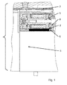
- drain 2 an element shaped from a high thermal conductivity material called drain 2, is used to capture and direct the heat flow by conduction.
- the drain 2 is placed between an electropneumatic pilot 1 and a metal body 3 of a pneumatic distributor 4 of a device according to the invention.
- the drain 2 is housed in a gap 5 provided between the electropneumatic pilot 1 and the metal body 3 of the pneumatic distributor 4.
- the drain 2 can be stressed in order to make permanent contact between the facing surfaces.
- the drain 2 can be realized in a elastic or rigid material or by polymerization (or solidification) of a liquid or pasty material ( figure 1 ).
- the electropneumatic pilot 1 may alternatively be completely integrated inside the pneumatic distributor 4, in a housing 8.
- An additional electronic circuit 7 may be positioned near the electropneumatic pilot 1, inside the pneumatic distributor 4.
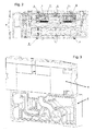
- Several drivers electropneumatic devices can be integrated within the same pneumatic distributor ( figure 2 ).
- the pneumatic distributor 4 can also be assembled on a metal base 6.
- drains can also advantageously be added in the pneumatic distributor 4 and / or in the metal base 6, and / or between these two elements, in order to increase the conduction of the heat flow and the heat dissipation of the whole of the pneumatic distributor (s) 4 mounted on the metal base 6.
- the device according to the invention makes it possible to increase the exchange surface with the external medium, but also the use of the base pneumatic and circulating compressed air flow such as in particular the common supply and exhaust distribution islands.
Landscapes
- Engineering & Computer Science (AREA)
- General Engineering & Computer Science (AREA)
- Mechanical Engineering (AREA)
- Cooling Or The Like Of Electrical Apparatus (AREA)
- Cooling Or The Like Of Semiconductors Or Solid State Devices (AREA)
- Details Of Valves (AREA)
- Magnetically Actuated Valves (AREA)
- Temperature-Responsive Valves (AREA)
- Physical Or Chemical Processes And Apparatus (AREA)
- Fluid-Pressure Circuits (AREA)
Description
- La puissance de l'air comprimé destinée aux vérins et moteurs doit être contrôlée. Le distributeur situé entre la source d'énergie pneumatique et l'actionneur remplit cette fonction.
- Ces distributeurs pneumatiques nécessitent généralement l'utilisation de vannes pilotes électropneumatiques pour permettre leur commande de basculement d'état. Ces pilotes électropneumatiques sont généralement de type électromagnétique et génèrent de ce fait un échauffement lié à l'effet Joule dû au courant électrique parcourant la bobine inductrice.
- Dans le but de limiter cet échauffement, il est d'usage : soit de limiter la puissance de la bobine, mais la performance pneumatique se trouve alors dégradée, soit de positionner les pilotes électropneumatiques de manière à évacuer directement leur chaleur vers l'extérieur. Cette construction contraint fortement les connexions pneumatiques et électriques et impacte de ce fait le dimensionnel du distributeur pneumatique.
- Des solutions pour la dissipation de chaleur sont mentionnées par exemple dans les documents
US2003/0115950 ,US6427970 ouUS5769508 . - Cet inconvénient est encore plus important dans le cas d'îlots de distribution pneumatique composés de plusieurs distributeurs pneumatiques juxtaposés. Cette juxtaposition en confinant les sources thermiques, abaisse encore les capacités d'échange thermique avec l'extérieur.
- Cette problématique d'échange thermique et de son amélioration est connue des fabricants de composants électriques.
- Dans le domaine des transformateurs électriques la solution présentée dans le brevet
JP2010027733 - Malheureusement ces solutions se sont révélées insuffisantes pour évacuer suffisamment de chaleur et garantir un fonctionnement optimal des dispositifs.
- L'invention a donc pour but, surtout, de proposer un dispositif permettant d'optimiser les échanges thermiques vers l'extérieur.
- Selon l'invention un dispositif de distribution pneumatique comprenant au moins une vanne pilote électromagnétique, un corp de distribution et au moins un drain thermique présentant une conductivité thermique mesurée suivant la norme ASTM D5470 supérieure ou égale à 0.5 W/m-K, le drain thermique étant disposé entre au moins une vanne pilote électromagnétique et le corps de distribution.
- Le dispositif de distribution pneumatique comprend également une ligne de distribution pneumatique associée à une chemise et un tiroir mobile à étanchéité élastomère ou glissante dite « métal / métal », avec ou sans dispositif de commande manuelle et avec ou sans circuit imprimé liant les pilotes aux circuits de commande électrique. Dans le cas de l'utilisation d'un circuit imprimé, le drain thermique autorise une plus grande proximité entre le pilote et les composants électroniques du circuit sans risque d'endommagement des composants du circuit grâce à une meilleure évacuation de la chaleur générée par le pilote.
- Une embase pneumatique simple est également prévue, cas d'un distributeur isolé, ou une embase pneumatique juxtaposable pour constituer un ilot de distribution.
- L'utilisation d'un ou plusieurs drains thermiques permettant le captage et l'orientation du flux thermique émit par ceux-ci permet d'obtenir une limitation de l'échauffement des pilotes électromagnétiques. Il est également envisageable d'associer ces drains à l'assemblage du corps de distribution et de l'embase pneumatique, afin d'augmenter encore la capacité d'échange thermique entre ces deux parties.
- De manière avantageuse le drain thermique présente une conductivité thermique mesurée suivant la norme ASTM D5470 supérieure ou égale à 0.9 W/m-K.
- De manière plus avantageuse le drain thermique présente une conductivité thermique mesurée suivant la norme ASTM D5470 supérieure ou égale à 1.2 W/m-K.
- Le dispositif peut être assemblé sur une embase pneumatique métallique, au moins un drain thermique étant interposé entre le corps de distribution et l'embase pneumatique.
- Le drain thermique peut présenter une dureté Shore 00 mesurée suivant la norme ASTM D 2240 comprise entre 30 et 80.
- De manière avantageuse le drain thermique présente une dureté Shore 00 mesurée suivant la norme ASTM D 2240 comprise entre 40 et 70.
- De manière plus avantageuse le drain thermique présente une dureté Shore 00 mesurée suivant la norme ASTM D 2240 comprise entre 40 et 50.
- Le drain thermique peut être obtenu par polymérisation ou solidification d'un matériau liquide ou pâteux.
- D'autres caractéristiques et avantages de l'invention apparaîtront dans la description qui suit d'un mode de réalisation préféré (distributeur bistable avec deux pilotes électromagnétiques et embase pneumatique juxtaposable) avec référence aux dessins annexés mais qui n'a aucun caractère limitatif. Sur ces dessins :
- La
figure 1 est un schéma illustrant le détail de montage d'un drain thermique selon l'invention entre le pilote et le corps de distribution. - La
figure 2 est un schéma illustrant l'ensemble du corps de distribution avec la disposition des pilotes et leur drain respectif ainsi que les drains sur le corps de distribution. - La
figure 3 représente le corps de distribution monté sur l'embase pneumatique. - La
figure 4 représente un mode de réalisation en ilot de distribution pneumatique. - Il est visible sur les
figures 1 à 4 qu'un élément mis en forme à partir d'un matériau à haute conductivité thermique appelé drain 2, est utilisé pour capter et orienter par conduction le flux thermique. Le drain 2 est placé entre un pilote électropneumatique 1 et un corps métallique 3 d'un distributeur pneumatique 4 d'un dispositif selon l'invention. Le drain 2 est logé dans un interstice 5 prévu entre le pilote électropneumatique 1 et le corps métallique 3 du distributeur pneumatique 4. - Le drain 2 peut être mis en contrainte afin de rendre le contact permanent entre les surfaces en regard. Le drain 2 peut être réalisé dans un matériau élastique ou rigide ou par polymérisation (ou solidification) d'un matériau liquide ou pâteux (
figure 1 ). - Comme drain 2, on peut citer les pads 1000SF de la société Bergquist d'une conductivité thermique mesurée suivant la norme ASTM D5470 de 0,9 W/m-K pour une épaisseur de 0.254 à 3.175 mm et une dureté Shore 00 mesurée suivant la norme ASTM D 2240 de 40 ou les pads 575-NS de la société Parker d'une conductivité thermique mesurée suivant la norme ASTM D5470 de 1,2 W/m-K pour une épaisseur de 0.5 à 2.5 mm et une dureté Shore 00 mesurée suivant la norme ASTM D 2240 de 70.
- De nombreuses variantes sont possibles à partir du mode de réalisation principal précédemment décrit.
- Le pilote électropneumatique 1 peut en variante être intégré complètement à l'intérieur du distributeur pneumatique 4, dans un boîtier 8. Un circuit électronique 7 additionnel peut être positionné à proximité du pilote électropneumatique 1, à l'intérieur du distributeur pneumatique 4. Plusieurs pilotes électropneumatiques peuvent être intégrés au sein du même distributeur pneumatique (
figure 2 ). - Le distributeur pneumatique 4 peut également être assemblé sur une embase métallique 6.
- Plusieurs drains peuvent également être ajoutés avantageusement dans le distributeur pneumatique 4 et/ou dans l'embase métallique 6, et/ou entre ces deux éléments, afin d'augmenter la conduction du flux thermique et la dissipation thermique de l'ensemble du ou des distributeur(s) pneumatique(s) 4 monté(s) sur l'embase métallique 6.
- En particulier il est possible d'utiliser la capacité de dissipation thermique liée à la circulation de l'air comprimée dans les communs d'alimentation et d'échappement de l'embase, mais aussi d'utiliser les effets thermodynamiques intervenant dans le dispositif tels que le refroidissement par détente de l'air comprimé entre les orifices d'utilisation et d'échappement (
figures 2, 3 ). Ce même principe s'applique aussi au mode de réalisation en ilots de distribution (figure 4 ). - Le dispositif selon l'invention permet d'augmenter la surface d'échange avec le milieu extérieur, mais aussi l'utilisation de l'embase pneumatique et sa circulation de flux d'air comprimé tels que notamment les communs d'alimentation et d'échappement des ilots de distribution.
Claims (9)
- Dispositif de distribution pneumatique comprenant au moins une vanne pilote électromagnétique (1), un corps de distribution (3) et au moins un drain thermique (2), présentant une conductivité thermique mesurée suivant la norme ASTM D5470 supérieure ou égale à 0.5 W/m-K, le drain thermique étant disposé entre au moins une vanne pilote électromagnétique (1) et le corps de distribution (3).
- Dispositif de distribution pneumatique selon la revendication 1, caractérisé en ce que le drain thermique (2) présente une conductivité thermique mesurée suivant la norme ASTM D5470 supérieure ou égale à 0.9 W/m-K.
- Dispositif de distribution pneumatique selon la revendication 1, caractérisé en ce que le drain thermique présente une conductivité thermique mesurée suivant la norme ASTM D5470 supérieure ou égale à 1.2 W/m-K.
- Dispositif de distribution pneumatique selon l'une quelconque des revendications précédentes, caractérisé en ce que le dispositif est assemblé sur une embase pneumatique métallique [6], au moins un drain thermique étant interposé entre le corps de distribution et l'embase pneumatique.
- Dispositif de distribution pneumatique selon l'une quelconque des revendications précédentes, caractérisé en ce que le drain thermique présente une dureté Shore 00 mesurée suivant la norme ASTM D 2240 comprise entre 30 et 80.
- Dispositif de distribution pneumatique selon l'une quelconque des revendications précédentes, caractérisé en ce que le drain thermique présente une dureté Shore 00 mesurée suivant la norme ASTM D 2240 comprise entre 40 et 70.
- Dispositif de distribution pneumatique selon l'une quelconque des revendications précédentes, caractérisé en ce que le drain thermique présente une dureté Shore 00 mesurée suivant la norme ASTM D 2240 comprise entre 40 et 50.
- Dispositif de distribution pneumatique selon l'une quelconque des revendications précédentes, caractérisé en ce que le drain thermique est obtenu par polymérisation ou solidification d'un matériau liquide ou pâteux.
- Dispositif de distribution pneumatique selon l'une quelconque des revendications précédentes, caractérisé en que au moins une vanne pilote est intégrée dans le corps de distribution.
Applications Claiming Priority (1)
| Application Number | Priority Date | Filing Date | Title |
|---|---|---|---|
| FR1256001A FR2992397B1 (fr) | 2012-06-25 | 2012-06-25 | Vanne pilote electropneumatique avec drain thermique |
Publications (2)
| Publication Number | Publication Date |
|---|---|
| EP2679870A1 EP2679870A1 (fr) | 2014-01-01 |
| EP2679870B1 true EP2679870B1 (fr) | 2014-09-03 |
Family
ID=46785668
Family Applications (1)
| Application Number | Title | Priority Date | Filing Date |
|---|---|---|---|
| EP20130173374 Active EP2679870B1 (fr) | 2012-06-25 | 2013-06-24 | Vanne pilote électropneumatique avec drain thermique |
Country Status (6)
| Country | Link |
|---|---|
| US (1) | US20130340844A1 (fr) |
| EP (1) | EP2679870B1 (fr) |
| JP (1) | JP6285114B2 (fr) |
| CN (1) | CN103511733B (fr) |
| ES (1) | ES2523987T3 (fr) |
| FR (1) | FR2992397B1 (fr) |
Family Cites Families (13)
| Publication number | Priority date | Publication date | Assignee | Title |
|---|---|---|---|---|
| DE19512804C2 (de) * | 1995-04-05 | 2000-06-15 | Lucas Ind Plc | Hydraulikaggregat für eine blockiergeschützte Fahrzeugbremsanlage |
| US6202672B1 (en) * | 1997-08-25 | 2001-03-20 | Hill-Rom, Inc. | Valve assembly |
| US6427970B1 (en) * | 2001-03-16 | 2002-08-06 | Young & Franklin, Inc. | Heat dissipating voice coil activated valves |
| US6668641B2 (en) * | 2001-12-21 | 2003-12-30 | Mks Instruments, Inc. | Apparatus and method for thermal dissipation in a thermal mass flow sensor |
| JP4712385B2 (ja) * | 2002-09-06 | 2011-06-29 | ヒル−ロム サービシーズ,インコーポレイティド | 病院ベッド |
| JP4499984B2 (ja) * | 2002-11-08 | 2010-07-14 | 株式会社堀場エステック | 高温対応バルブ |
| JP2005036928A (ja) * | 2003-07-17 | 2005-02-10 | Advics:Kk | 電磁弁 |
| US7195482B2 (en) * | 2003-12-30 | 2007-03-27 | Ultradent Products, Inc. | Dental curing device having a heat sink for dissipating heat |
| JP4677805B2 (ja) * | 2005-03-22 | 2011-04-27 | 株式会社フジキン | 流体制御装置 |
| US7402193B2 (en) * | 2005-04-05 | 2008-07-22 | Respironics Oxytec, Inc. | Portable oxygen concentrator |
| CN1964028B (zh) * | 2005-11-11 | 2010-08-18 | 鸿富锦精密工业(深圳)有限公司 | 散热器 |
| JP2010027733A (ja) | 2008-07-16 | 2010-02-04 | Daikin Ind Ltd | リアクトルの冷却構造 |
| CN201386213Y (zh) * | 2008-12-29 | 2010-01-20 | 博西威家用电器有限公司 | 家用电器的进水阀系统 |
-
2012
- 2012-06-25 FR FR1256001A patent/FR2992397B1/fr not_active Expired - Fee Related
-
2013
- 2013-06-21 JP JP2013130812A patent/JP6285114B2/ja active Active
- 2013-06-24 ES ES13173374.3T patent/ES2523987T3/es active Active
- 2013-06-24 US US13/925,140 patent/US20130340844A1/en not_active Abandoned
- 2013-06-24 EP EP20130173374 patent/EP2679870B1/fr active Active
- 2013-06-25 CN CN201310256099.7A patent/CN103511733B/zh active Active
Also Published As
| Publication number | Publication date |
|---|---|
| CN103511733B (zh) | 2018-01-19 |
| EP2679870A1 (fr) | 2014-01-01 |
| CN103511733A (zh) | 2014-01-15 |
| US20130340844A1 (en) | 2013-12-26 |
| FR2992397B1 (fr) | 2014-08-01 |
| JP2014005939A (ja) | 2014-01-16 |
| JP6285114B2 (ja) | 2018-02-28 |
| FR2992397A1 (fr) | 2013-12-27 |
| ES2523987T3 (es) | 2014-12-03 |
Similar Documents
| Publication | Publication Date | Title |
|---|---|---|
| EP2993435B1 (fr) | Plaque d'échange thermique pour gestion thermique de pack batteries | |
| WO2007089874A3 (fr) | Dispositifs de diode thermique pour applications a vitesse de refroidissement elevee et leurs procedes de fabrication | |
| TW200735322A (en) | High power light emitting device assembly with ESD preotection ability and the method of manufacturing the same | |
| US20190109516A1 (en) | Fluid pump with heat dissipation | |
| WO2007090664A3 (fr) | Dispositif électronique de puissance | |
| TW201528927A (zh) | 新構裝散熱設計 | |
| FR3016266A1 (fr) | Dispositif electronique de puissance a refroidissement ameliore | |
| TW200723484A (en) | Laser fuse with efficient heat dissipation | |
| TW200720455A (en) | Monolithic sputter target backing plate with integrated cooling passages | |
| WO2003085500A3 (fr) | Dissipation thermique sur des appareils comportant une source d'energie interne | |
| EP2679870A1 (fr) | Vanne pilote électropneumatique avec drain thermique | |
| FR2934749A1 (fr) | Dispositif de blindage electromagnetique et de dissipation de chaleur degagee par un composant electronique et circuit electronique correspondant. | |
| FR2701190A1 (fr) | Disposition pour évacuer la chaleur dégagée par des composants de puissance montés sur des circuits imprimés. | |
| FR2517330A1 (fr) | Appareil de projection de metal sur un substrat, en particulier du type a magnetron | |
| EP1742264A3 (fr) | Module monolithique de puissance refroidi par fluide et méthode de fabrication | |
| JP5535003B2 (ja) | 半導体ウエハ冷却装置 | |
| US8297532B2 (en) | Apparatus for cooling a fuel injector | |
| CN205912405U (zh) | 散热结构和手持装置 | |
| TWI658615B (zh) | 熱電產生器 | |
| WO2008118937A3 (fr) | Dispositifs thermoélectriques et leurs procédés de fabrication | |
| KR101207934B1 (ko) | 방열판 구조 | |
| WO2020234544A1 (fr) | Régulateur poreux à ventilation intégrée | |
| FR3070231B1 (fr) | Equipement electronique comprenant une bride de fixation | |
| CN203453525U (zh) | 电动硬密封球阀 | |
| WO2020016215A1 (fr) | Dispositif de dissipation thermique muni d'une plaque froide secondaire |
Legal Events
| Date | Code | Title | Description |
|---|---|---|---|
| PUAI | Public reference made under article 153(3) epc to a published international application that has entered the european phase |
Free format text: ORIGINAL CODE: 0009012 |
|
| 17P | Request for examination filed |
Effective date: 20130624 |
|
| AK | Designated contracting states |
Kind code of ref document: A1 Designated state(s): AL AT BE BG CH CY CZ DE DK EE ES FI FR GB GR HR HU IE IS IT LI LT LU LV MC MK MT NL NO PL PT RO RS SE SI SK SM TR |
|
| AX | Request for extension of the european patent |
Extension state: BA ME |
|
| GRAP | Despatch of communication of intention to grant a patent |
Free format text: ORIGINAL CODE: EPIDOSNIGR1 |
|
| RIC1 | Information provided on ipc code assigned before grant |
Ipc: F16K 49/00 20060101AFI20140307BHEP Ipc: F16K 31/06 20060101ALI20140307BHEP |
|
| INTG | Intention to grant announced |
Effective date: 20140410 |
|
| GRAS | Grant fee paid |
Free format text: ORIGINAL CODE: EPIDOSNIGR3 |
|
| GRAA | (expected) grant |
Free format text: ORIGINAL CODE: 0009210 |
|
| RBV | Designated contracting states (corrected) |
Designated state(s): AL AT BE BG CH CY CZ DE DK EE ES FI FR GB GR HR HU IE IS IT LI LT LU LV MC MK MT NL NO PL PT RO RS SE SI SK SM TR |
|
| AK | Designated contracting states |
Kind code of ref document: B1 Designated state(s): AL AT BE BG CH CY CZ DE DK EE ES FI FR GB GR HR HU IE IS IT LI LT LU LV MC MK MT NL NO PL PT RO RS SE SI SK SM TR |
|
| REG | Reference to a national code |
Ref country code: GB Ref legal event code: FG4D Free format text: NOT ENGLISH |
|
| REG | Reference to a national code |
Ref country code: CH Ref legal event code: EP Ref country code: AT Ref legal event code: REF Ref document number: 685807 Country of ref document: AT Kind code of ref document: T Effective date: 20140915 |
|
| REG | Reference to a national code |
Ref country code: IE Ref legal event code: FG4D Free format text: LANGUAGE OF EP DOCUMENT: FRENCH |
|
| REG | Reference to a national code |
Ref country code: DE Ref legal event code: R096 Ref document number: 602013000223 Country of ref document: DE Effective date: 20141016 |
|
| REG | Reference to a national code |
Ref country code: ES Ref legal event code: FG2A Ref document number: 2523987 Country of ref document: ES Kind code of ref document: T3 Effective date: 20141203 |
|
| REG | Reference to a national code |
Ref country code: AT Ref legal event code: MK05 Ref document number: 685807 Country of ref document: AT Kind code of ref document: T Effective date: 20140903 |
|
| PG25 | Lapsed in a contracting state [announced via postgrant information from national office to epo] |
Ref country code: SE Free format text: LAPSE BECAUSE OF FAILURE TO SUBMIT A TRANSLATION OF THE DESCRIPTION OR TO PAY THE FEE WITHIN THE PRESCRIBED TIME-LIMIT Effective date: 20140903 Ref country code: GR Free format text: LAPSE BECAUSE OF FAILURE TO SUBMIT A TRANSLATION OF THE DESCRIPTION OR TO PAY THE FEE WITHIN THE PRESCRIBED TIME-LIMIT Effective date: 20141204 Ref country code: LT Free format text: LAPSE BECAUSE OF FAILURE TO SUBMIT A TRANSLATION OF THE DESCRIPTION OR TO PAY THE FEE WITHIN THE PRESCRIBED TIME-LIMIT Effective date: 20140903 Ref country code: NO Free format text: LAPSE BECAUSE OF FAILURE TO SUBMIT A TRANSLATION OF THE DESCRIPTION OR TO PAY THE FEE WITHIN THE PRESCRIBED TIME-LIMIT Effective date: 20141203 Ref country code: FI Free format text: LAPSE BECAUSE OF FAILURE TO SUBMIT A TRANSLATION OF THE DESCRIPTION OR TO PAY THE FEE WITHIN THE PRESCRIBED TIME-LIMIT Effective date: 20140903 |
|
| REG | Reference to a national code |
Ref country code: NL Ref legal event code: VDEP Effective date: 20140903 |
|
| REG | Reference to a national code |
Ref country code: LT Ref legal event code: MG4D |
|
| PG25 | Lapsed in a contracting state [announced via postgrant information from national office to epo] |
Ref country code: CY Free format text: LAPSE BECAUSE OF FAILURE TO SUBMIT A TRANSLATION OF THE DESCRIPTION OR TO PAY THE FEE WITHIN THE PRESCRIBED TIME-LIMIT Effective date: 20140903 Ref country code: RS Free format text: LAPSE BECAUSE OF FAILURE TO SUBMIT A TRANSLATION OF THE DESCRIPTION OR TO PAY THE FEE WITHIN THE PRESCRIBED TIME-LIMIT Effective date: 20140903 Ref country code: LV Free format text: LAPSE BECAUSE OF FAILURE TO SUBMIT A TRANSLATION OF THE DESCRIPTION OR TO PAY THE FEE WITHIN THE PRESCRIBED TIME-LIMIT Effective date: 20140903 Ref country code: HR Free format text: LAPSE BECAUSE OF FAILURE TO SUBMIT A TRANSLATION OF THE DESCRIPTION OR TO PAY THE FEE WITHIN THE PRESCRIBED TIME-LIMIT Effective date: 20140903 Ref country code: AT Free format text: LAPSE BECAUSE OF FAILURE TO SUBMIT A TRANSLATION OF THE DESCRIPTION OR TO PAY THE FEE WITHIN THE PRESCRIBED TIME-LIMIT Effective date: 20140903 |
|
| PG25 | Lapsed in a contracting state [announced via postgrant information from national office to epo] |
Ref country code: NL Free format text: LAPSE BECAUSE OF FAILURE TO SUBMIT A TRANSLATION OF THE DESCRIPTION OR TO PAY THE FEE WITHIN THE PRESCRIBED TIME-LIMIT Effective date: 20140903 |
|
| PG25 | Lapsed in a contracting state [announced via postgrant information from national office to epo] |
Ref country code: EE Free format text: LAPSE BECAUSE OF FAILURE TO SUBMIT A TRANSLATION OF THE DESCRIPTION OR TO PAY THE FEE WITHIN THE PRESCRIBED TIME-LIMIT Effective date: 20140903 Ref country code: PT Free format text: LAPSE BECAUSE OF FAILURE TO SUBMIT A TRANSLATION OF THE DESCRIPTION OR TO PAY THE FEE WITHIN THE PRESCRIBED TIME-LIMIT Effective date: 20150105 Ref country code: SK Free format text: LAPSE BECAUSE OF FAILURE TO SUBMIT A TRANSLATION OF THE DESCRIPTION OR TO PAY THE FEE WITHIN THE PRESCRIBED TIME-LIMIT Effective date: 20140903 Ref country code: IS Free format text: LAPSE BECAUSE OF FAILURE TO SUBMIT A TRANSLATION OF THE DESCRIPTION OR TO PAY THE FEE WITHIN THE PRESCRIBED TIME-LIMIT Effective date: 20150103 Ref country code: RO Free format text: LAPSE BECAUSE OF FAILURE TO SUBMIT A TRANSLATION OF THE DESCRIPTION OR TO PAY THE FEE WITHIN THE PRESCRIBED TIME-LIMIT Effective date: 20140903 Ref country code: CZ Free format text: LAPSE BECAUSE OF FAILURE TO SUBMIT A TRANSLATION OF THE DESCRIPTION OR TO PAY THE FEE WITHIN THE PRESCRIBED TIME-LIMIT Effective date: 20140903 |
|
| PG25 | Lapsed in a contracting state [announced via postgrant information from national office to epo] |
Ref country code: PL Free format text: LAPSE BECAUSE OF FAILURE TO SUBMIT A TRANSLATION OF THE DESCRIPTION OR TO PAY THE FEE WITHIN THE PRESCRIBED TIME-LIMIT Effective date: 20140903 |
|
| REG | Reference to a national code |
Ref country code: DE Ref legal event code: R097 Ref document number: 602013000223 Country of ref document: DE |
|
| PLBE | No opposition filed within time limit |
Free format text: ORIGINAL CODE: 0009261 |
|
| STAA | Information on the status of an ep patent application or granted ep patent |
Free format text: STATUS: NO OPPOSITION FILED WITHIN TIME LIMIT |
|
| PG25 | Lapsed in a contracting state [announced via postgrant information from national office to epo] |
Ref country code: DK Free format text: LAPSE BECAUSE OF FAILURE TO SUBMIT A TRANSLATION OF THE DESCRIPTION OR TO PAY THE FEE WITHIN THE PRESCRIBED TIME-LIMIT Effective date: 20140903 |
|
| 26N | No opposition filed |
Effective date: 20150604 |
|
| PG25 | Lapsed in a contracting state [announced via postgrant information from national office to epo] |
Ref country code: SI Free format text: LAPSE BECAUSE OF FAILURE TO SUBMIT A TRANSLATION OF THE DESCRIPTION OR TO PAY THE FEE WITHIN THE PRESCRIBED TIME-LIMIT Effective date: 20140903 |
|
| PG25 | Lapsed in a contracting state [announced via postgrant information from national office to epo] |
Ref country code: MC Free format text: LAPSE BECAUSE OF FAILURE TO SUBMIT A TRANSLATION OF THE DESCRIPTION OR TO PAY THE FEE WITHIN THE PRESCRIBED TIME-LIMIT Effective date: 20140903 |
|
| PG25 | Lapsed in a contracting state [announced via postgrant information from national office to epo] |
Ref country code: LU Free format text: LAPSE BECAUSE OF FAILURE TO SUBMIT A TRANSLATION OF THE DESCRIPTION OR TO PAY THE FEE WITHIN THE PRESCRIBED TIME-LIMIT Effective date: 20150624 |
|
| REG | Reference to a national code |
Ref country code: IE Ref legal event code: MM4A |
|
| PG25 | Lapsed in a contracting state [announced via postgrant information from national office to epo] |
Ref country code: IE Free format text: LAPSE BECAUSE OF NON-PAYMENT OF DUE FEES Effective date: 20150624 |
|
| REG | Reference to a national code |
Ref country code: FR Ref legal event code: PLFP Year of fee payment: 4 |
|
| PG25 | Lapsed in a contracting state [announced via postgrant information from national office to epo] |
Ref country code: MT Free format text: LAPSE BECAUSE OF FAILURE TO SUBMIT A TRANSLATION OF THE DESCRIPTION OR TO PAY THE FEE WITHIN THE PRESCRIBED TIME-LIMIT Effective date: 20140903 |
|
| REG | Reference to a national code |
Ref country code: CH Ref legal event code: PL |
|
| PG25 | Lapsed in a contracting state [announced via postgrant information from national office to epo] |
Ref country code: CH Free format text: LAPSE BECAUSE OF NON-PAYMENT OF DUE FEES Effective date: 20160630 Ref country code: LI Free format text: LAPSE BECAUSE OF NON-PAYMENT OF DUE FEES Effective date: 20160630 |
|
| PG25 | Lapsed in a contracting state [announced via postgrant information from national office to epo] |
Ref country code: HU Free format text: LAPSE BECAUSE OF FAILURE TO SUBMIT A TRANSLATION OF THE DESCRIPTION OR TO PAY THE FEE WITHIN THE PRESCRIBED TIME-LIMIT; INVALID AB INITIO Effective date: 20130624 Ref country code: BG Free format text: LAPSE BECAUSE OF FAILURE TO SUBMIT A TRANSLATION OF THE DESCRIPTION OR TO PAY THE FEE WITHIN THE PRESCRIBED TIME-LIMIT Effective date: 20140903 |
|
| REG | Reference to a national code |
Ref country code: FR Ref legal event code: PLFP Year of fee payment: 5 |
|
| PG25 | Lapsed in a contracting state [announced via postgrant information from national office to epo] |
Ref country code: BE Free format text: LAPSE BECAUSE OF NON-PAYMENT OF DUE FEES Effective date: 20150630 |
|
| PG25 | Lapsed in a contracting state [announced via postgrant information from national office to epo] |
Ref country code: TR Free format text: LAPSE BECAUSE OF FAILURE TO SUBMIT A TRANSLATION OF THE DESCRIPTION OR TO PAY THE FEE WITHIN THE PRESCRIBED TIME-LIMIT Effective date: 20140903 |
|
| GBPC | Gb: european patent ceased through non-payment of renewal fee |
Effective date: 20170624 |
|
| PG25 | Lapsed in a contracting state [announced via postgrant information from national office to epo] |
Ref country code: GB Free format text: LAPSE BECAUSE OF NON-PAYMENT OF DUE FEES Effective date: 20170624 |
|
| PG25 | Lapsed in a contracting state [announced via postgrant information from national office to epo] |
Ref country code: SM Free format text: LAPSE BECAUSE OF FAILURE TO SUBMIT A TRANSLATION OF THE DESCRIPTION OR TO PAY THE FEE WITHIN THE PRESCRIBED TIME-LIMIT Effective date: 20140903 |
|
| REG | Reference to a national code |
Ref country code: FR Ref legal event code: PLFP Year of fee payment: 6 |
|
| PG25 | Lapsed in a contracting state [announced via postgrant information from national office to epo] |
Ref country code: MK Free format text: LAPSE BECAUSE OF FAILURE TO SUBMIT A TRANSLATION OF THE DESCRIPTION OR TO PAY THE FEE WITHIN THE PRESCRIBED TIME-LIMIT Effective date: 20140903 |
|
| PG25 | Lapsed in a contracting state [announced via postgrant information from national office to epo] |
Ref country code: AL Free format text: LAPSE BECAUSE OF FAILURE TO SUBMIT A TRANSLATION OF THE DESCRIPTION OR TO PAY THE FEE WITHIN THE PRESCRIBED TIME-LIMIT Effective date: 20140903 |
|
| P01 | Opt-out of the competence of the unified patent court (upc) registered |
Effective date: 20240503 |
|
| PGFP | Annual fee paid to national office [announced via postgrant information from national office to epo] |
Ref country code: DE Payment date: 20240521 Year of fee payment: 12 |
|
| PGFP | Annual fee paid to national office [announced via postgrant information from national office to epo] |
Ref country code: IT Payment date: 20240522 Year of fee payment: 12 Ref country code: FR Payment date: 20240521 Year of fee payment: 12 |
|
| PGFP | Annual fee paid to national office [announced via postgrant information from national office to epo] |
Ref country code: ES Payment date: 20240701 Year of fee payment: 12 |
|
| REG | Reference to a national code |
Ref country code: DE Ref legal event code: R119 Ref document number: 602013000223 Country of ref document: DE |
|
| PG25 | Lapsed in a contracting state [announced via postgrant information from national office to epo] |
Ref country code: DE Free format text: LAPSE BECAUSE OF NON-PAYMENT OF DUE FEES Effective date: 20260101 |
|
| PG25 | Lapsed in a contracting state [announced via postgrant information from national office to epo] |
Ref country code: IT Free format text: LAPSE BECAUSE OF NON-PAYMENT OF DUE FEES Effective date: 20250624 |
|
| PG25 | Lapsed in a contracting state [announced via postgrant information from national office to epo] |
Ref country code: FR Free format text: LAPSE BECAUSE OF NON-PAYMENT OF DUE FEES Effective date: 20250630 |