EP2679856A1 - Air spring apparatus - Google Patents
Air spring apparatus Download PDFInfo
- Publication number
- EP2679856A1 EP2679856A1 EP12749106.6A EP12749106A EP2679856A1 EP 2679856 A1 EP2679856 A1 EP 2679856A1 EP 12749106 A EP12749106 A EP 12749106A EP 2679856 A1 EP2679856 A1 EP 2679856A1
- Authority
- EP
- European Patent Office
- Prior art keywords
- section
- contact
- engaging
- axial line
- support section
- Prior art date
- Legal status (The legal status is an assumption and is not a legal conclusion. Google has not performed a legal analysis and makes no representation as to the accuracy of the status listed.)
- Granted
Links
Images
Classifications
-
- B—PERFORMING OPERATIONS; TRANSPORTING
- B61—RAILWAYS
- B61F—RAIL VEHICLE SUSPENSIONS, e.g. UNDERFRAMES, BOGIES OR ARRANGEMENTS OF WHEEL AXLES; RAIL VEHICLES FOR USE ON TRACKS OF DIFFERENT WIDTH; PREVENTING DERAILING OF RAIL VEHICLES; WHEEL GUARDS, OBSTRUCTION REMOVERS OR THE LIKE FOR RAIL VEHICLES
- B61F5/00—Constructional details of bogies; Connections between bogies and vehicle underframes; Arrangements or devices for adjusting or allowing self-adjustment of wheel axles or bogies when rounding curves
- B61F5/02—Arrangements permitting limited transverse relative movements between vehicle underframe or bolster and bogie; Connections between underframes and bogies
-
- F—MECHANICAL ENGINEERING; LIGHTING; HEATING; WEAPONS; BLASTING
- F16—ENGINEERING ELEMENTS AND UNITS; GENERAL MEASURES FOR PRODUCING AND MAINTAINING EFFECTIVE FUNCTIONING OF MACHINES OR INSTALLATIONS; THERMAL INSULATION IN GENERAL
- F16F—SPRINGS; SHOCK-ABSORBERS; MEANS FOR DAMPING VIBRATION
- F16F13/00—Units comprising springs of the non-fluid type as well as vibration-dampers, shock-absorbers, or fluid springs
- F16F13/002—Units comprising springs of the non-fluid type as well as vibration-dampers, shock-absorbers, or fluid springs comprising at least one fluid spring
-
- F—MECHANICAL ENGINEERING; LIGHTING; HEATING; WEAPONS; BLASTING
- F16—ENGINEERING ELEMENTS AND UNITS; GENERAL MEASURES FOR PRODUCING AND MAINTAINING EFFECTIVE FUNCTIONING OF MACHINES OR INSTALLATIONS; THERMAL INSULATION IN GENERAL
- F16F—SPRINGS; SHOCK-ABSORBERS; MEANS FOR DAMPING VIBRATION
- F16F9/00—Springs, vibration-dampers, shock-absorbers, or similarly-constructed movement-dampers using a fluid or the equivalent as damping medium
- F16F9/02—Springs, vibration-dampers, shock-absorbers, or similarly-constructed movement-dampers using a fluid or the equivalent as damping medium using gas only or vacuum
- F16F9/04—Springs, vibration-dampers, shock-absorbers, or similarly-constructed movement-dampers using a fluid or the equivalent as damping medium using gas only or vacuum in a chamber with a flexible wall
- F16F9/05—Springs, vibration-dampers, shock-absorbers, or similarly-constructed movement-dampers using a fluid or the equivalent as damping medium using gas only or vacuum in a chamber with a flexible wall the flexible wall being of the rolling diaphragm type
Definitions
- the present invention relates to an air spring apparatus that is disposed, for example, between a body and a carriage of a railroad vehicle or the like.
- Priority is claimed on Japanese Patent Application No. 2011-040031, filed February 25, 2011 , the content of which is incorporated herein by reference.
- the air spring apparatus includes a diaphragm that has an upper member, a lower member, and a cylindrical membrane member having both open end sections connected to both members and sealed therewith. Furthermore, a sliding surface is formed on a lower surface of the upper member.
- the lower member is equipped with a slide plate with which the sliding surface of the upper member comes into contact in an exhaust state in which the interior of the diaphragm is exhausted, and a support section that supports the slide plate from the lower side thereof.
- the slide plate is formed of a resin material so as to reduce a coefficient of friction between the slide plate and the sliding surface, and is fixed to the upper surface of the support section by bonding.
- the sliding surface and the slide plate slide in the mutual contact state. Accordingly, it is possible to relatively move the upper member and the lower member in a radial direction.
- An aspect of the present invention was made in view of the above-mentioned circumstances, and an object thereof is to provide an air spring apparatus which is capable of suppressing the contact section from being detached from the support section.
- An air spring apparatus includes a diaphragm that has an upper member, a lower member, and a cylindrical membrane member having both open end sections connected to both the upper and lower members and sealed therewith, the upper member and the lower member being provided with contact sections that slidably come into contact with each other in an exhaust state in which the interior of the diaphragm is exhausted, wherein at least one of the upper member and the lower member having the contact sections, which are formed of a resin material, includes a support section that supports the contact section from the exterior of the diaphragm disposed in an axial line direction, and an engaging section that is provided in the contact section and controls respective relative movements of the contact section with respect to the support section in each of the axial line direction and the radial direction by being engaged with an engagement section that is provided in the support section.
- the engaging section is provided in the contact section that is supported by the support section. For this reason, the engaging section is engaged with the engagement section, which makes it possible to control each relative movement of the contact sections with respect to the support section in the axial line direction and the radial direction. Furthermore, it is possible to suppress the contact sections formed of a resin material supported by the support section from being detached from the support section when the contact sections slide in the mutual contact state.
- the engaging section in the contact section, it is possible to separately form the contact section and the support section while suppressing the contact section from being detached from the support section. Accordingly, for example, by forming the support section of a metallic material, durability of the lower member can be easily secured.
- At least one contact section of the upper member and the lower member is formed of a resin material.
- a material having a smaller coefficient of friction than a material that forms the support section as a resin material that forms the contact section, the coefficient of friction between the contact sections can be effectively reduced.
- the engaging section may be integrally provided in the contact section of the same resin material as the contact section provided with the engaging section.
- the engaging section is integrally formed with the contact section of the same resin material as the contact section provided with the engaging section. Accordingly, a connected body of the engaging section and the contact section can be integrally molded, for example, by injection molding or the like, and can be easily formed.
- the connected body can be integrally formed by the injection molding. Accordingly, when the connected body is molded, for example, by adopting insert molding in which the resin material is injected into a metal mold to mold the connector in a state in which the support section is disposed inside a metal mold, the engaging section can be engaged with the engagement section while forming the connected body. As a result, manufacturing work of the air spring apparatus can be simplified.
- the connected body is molded by the insert molding as mentioned above, it is possible to bring the connected body into close contact with the support section. As a result, it is possible to effectively suppress the contact section from being detached from the support section.
- the engagement section may be formed on an outer circumferential surface of the support section in a groove shape.
- the engaging section may include a cylindrical section that extends toward the exterior of the diaphragm disposed in the axial line direction from an outer circumferential edge of the contact section and is externally fitted to the support section, and a protrusion section that protrudes on an inner circumferential surface of the cylindrical section and is disposed in the engagement section.
- the cylindrical section of the engaging section is externally fitted to the support section, the relative movement in the radial direction between the contact section and the support section can be controlled by the contact between the inner circumferential surface of the cylindrical section and the outer circumferential surface of the support section. Furthermore, since the protrusion section of the engaging section is disposed in the engagement section, the relative movement in the axial line direction between the contact section and the support section can be controlled by the contact between the protrusion section and the inner surface of the engagement section.
- the cylindrical section extends toward the exterior of the diaphragm in the axial line direction from the outer circumferential edge of the contact section.
- the air spring apparatus related to a first aspect of the present invention, it is possible to suppress the contact section from being detached from the support section.
- an air spring apparatus 1 includes a diaphragm 5 that includes an upper surface plate (an upper member) 2, a lower surface plate (a lower member) 3, and a cylindrical membrane member 4 having open end sections 4a and 4b connected to the surface plates 2 and 3 and sealed therewith, and an intermediate portion 4c located between the open end sections 4a and 4b bulges toward the exterior in the radial direction, and an auxiliary elastic body 6 that is connected to the lower surface plate 3 of the diaphragm 5.
- the air spring apparatus 1 is provided, for example, between a body and a carriage (not shown) of a railroad vehicle or the like.
- the auxiliary elastic body 6 is formed in a cylindrical shape, and respective central axial lines of the upper surface plate 2, the lower surface plate 3, the cylindrical membrane member 4, and the auxiliary elastic body 6 are located on a common axial line.
- the common axis is assumed to be an axial line O
- the upper surface plate 2 side along the axial line O is assumed to be an upper side
- the lower surface plate 3 side is assumed to be a lower side
- a direction perpendicular to the axial line O is assumed to be a radial direction
- a direction rotating around the axial line O is assumed to be a circumferential direction.
- the auxiliary elastic body 6 is constituted by laminated rubber that includes an annular lower board 7, an annular upper board 8, and an annular rubber plate 9 and an annular metallic plate 10 that are alternately disposed in the axial line O direction between the boards 7 and 8.
- the lower board 7, the upper board 8, the rubber plate 9, and the metallic plate 10 are disposed coaxially with the axial line O.
- the lower board 7, the upper board 8, the metallic plate 10 and the rubber plate 9 are affixed by vulcanization.
- an outer diameter of the upper board 8 is the greatest, and the outer circumferential edge section of the upper board 8 protrudes outward in the radial direction.
- the inner diameter of the lower board 7 is the smallest, and the inner circumferential edge section of the lower board 7 protrudes inward in the radial direction.
- a communication cylinder section 7a the interior of which is opened toward both sides in the axial line O direction to communicate with the interior of the auxiliary elastic body 6, is fitted into the lower board 7.
- Air supplying member, an auxiliary tank or the like (not shown) for supplying and discharging the gas such as air into and from the diaphragm 5 is hermetically connected to a portion that protrudes downward from the lower board 7 in the communication cylinder section 7a.
- the lower surface plate 3 of the diaphragm 5 includes a resin plate section (contact section) 11 formed of a resin material, and a support section 12 that supports the resin plate section 11 from the lower side (the exterior of the diaphragm disposed in the axial line direction).
- the resin plate section 11 and the support section 12 are disposed coaxially with the axial line O.
- the support section 12 is formed of, for example, a metallic material or the like.
- the support section 12 is configured so that a large-diameter portion 12a and a small-diameter portion 12b disposed coaxially with the axial line O are connected to each other from the lower side (the exterior) in the axial line O direction in this sequence.
- An outer diameter of the large-diameter portion 12a of the support section 12 is smaller than an outer diameter of the upper board 8 of the auxiliary elastic body 6.
- the support section 12 is fixed to the upper board 8 of the auxiliary elastic body 6 by a fixing bolt 13.
- the lower surface plate 3 and the auxiliary elastic body 6 are hermetically connected to each other, and the communication between the interior and the exterior of the auxiliary elastic body 6 through the gap between the lower surface plate 3 and the auxiliary elastic body 6 is blocked.
- the support section 12 is formed with a plurality of bolt holes 14 through which the fixing bolts 13 are inserted.
- the bolt holes 14 penetrate the support section 12 in the axial line O direction, and are disposed at intervals in the circumferential direction in a plural number, as shown in FIG. 2 .
- the plurality of bolt holes 14 are disposed at equal intervals in a circumferential direction on the same circle around the axial line O in the top view as viewed from the upper side in the axial line O direction.
- the supplying and discharging hole 15 is disposed coaxially with the axial line O, and communicates with the interior of the communication cylinder section 7a through the interior of the auxiliary elastic body 6.
- a female screw section 15a is formed in the supplying and discharging hole 15, and a hanging bolt included in a hanging device (not shown) for lifting the lower surface plate 3 upward can be screwed into the female screw section 15a.
- an outer circumferential edge section located outside the support section 12 in the radial direction is covered by an annular rubber seat 16 from the upper side and the outer side in the radial direction.
- the inner circumferential edge of the rubber seat 16 is interposed between the support section 12 of the lower surface plate 3 and the upper board 8 of the auxiliary elastic body 6.
- the lower surface of the resin plate section 11 comes into surface contact with the upper surface of the support section 12. Furthermore, the outer diameter of the resin plate section 11 is equal to the outer diameter of the large-diameter portion 12a of the support section 12. The resin plate section 11 is thinner than the support section 12 in the axial line O direction. Furthermore, in the resin plate section 11, at a position corresponding to the bolt hole 14 of the support section 12, an insertion hole 11a, which is coaxial with the bolt hole 14 and has the same shape and the same size as viewed from the upper surface, is formed.
- a communication hole 11b which has a greater diameter than the supplying and discharging hole 15 and communicates with the supplying and discharging hole 15 and the interior of the diaphragm 5, is formed.
- the resin material for forming the resin plate section 11 it is preferable to use a material having a lower coefficient of friction than the material for forming the support section 12.
- a resin material for example, a thermoplastic resin, a thermosetting resin and the like are adopted, and preferably, polyethylene, polyacetal and the like are adopted.
- the upper surface plate 2 includes a main body plate section 17 that has an outer diameter greater than that of the cylindrical membrane member 4, and a projecting section (contact section) 18 that projects downward (toward the interior of the diaphragm in the axial line direction) from a central section in the radial direction in the main body plate section 17.
- the main body plate section 17 and the projecting section 18 are disposed coaxially with the axial line O.
- the projecting section 18 is formed in a closed-end cylindrical shape and faces the resin plate section 11 of the lower surface plate 3 in the axial line O direction.
- the outer diameter of the projecting section 18 is equal to the outer diameter of the resin plate section 11.
- an outer circumferential side portion located outside the projecting section 18 in the radial direction is covered by an annular rubber membrane 19 from the lower side.
- a radial gap is provided between the projecting section 18 and the rubber membrane 19.
- the upper surface plate 2 is provided with a penetration cylinder section 20 which penetrates the main body plate section 17 and the projecting section 18 in the axial line O direction, and through which the interior and the exterior of the diaphragm 5 communicate with each other.
- a lower end surface of the penetration cylinder section 20 is coplanar with the lower surface of the projecting section 18.
- An upper end section of the penetration cylinder section 20 protrudes above the main body plate section 17.
- the above-mentioned gas supplying member, auxiliary tank or the like is hermetically connected to the upper end section of the penetration cylinder section 20.
- the cylindrical membrane member 4 has flexibility, and is formed of, for example, an elastic body material, preferably, a rubber material or the like. Furthermore, the upper open end section 4a of the open end sections 4a and 4b of the cylindrical membrane member 4 is hermetically and externally fitted to the projecting section 18 of the upper surface plate 2, and is disposed in a gap between the projecting section 18 and the rubber membrane 19. Furthermore, the lower open end section 4b of the open end sections 4a and 4b is hermetically and externally fitted to the support section 12 of the lower surface plate 3, and is disposed on the rubber seat 16.
- the intermediate portion 4c of the cylindrical membrane member 4 protrudes outward from the upper board 8 of the auxiliary elastic body 6 in the radial direction.
- the intermediate portion 4c comes into contact with the upper board 8 of the auxiliary elastic body 6 from the upper side and the outer side in the radial direction via the rubber seat 16 provided on the lower surface plate 3 side.
- the intermediate portion 4c comes into contact with the main body plate section 17 of the upper surface plate 2 from the lower side via the rubber membrane 19 provided on the upper surface plate 2 side.
- the projecting section 18 of the upper surface plate 2 and the resin plate section 11 of the lower surface plate 3 are separated from each other in the axial line O direction and face each other in a filled state in which the gas is filled in the diaphragm 5. As shown in FIG. 3 , the projecting section 18 and the resin plate section 11 slidably come into contact with each other in the exhaust state in which the interior of the diaphragm 5 is exhausted.
- a diaphragm space S is formed to include a central space S1 located between the projecting section 18 of the upper surface plate 2 and the resin plate section 11 of the lower surface plate 3, and an outer circumferential space S2 which is located in the cylindrical membrane member 4, extends over the whole circumference, and is connected to the central space S1 from the outer side in the radial direction.
- the interior of the penetration cylinder section 20 of the upper surface plate 2 side and the supplying and discharging hole 15 of the lower surface plate 3 side communicate with the outer circumferential space S2 in the cylindrical membrane member 4 through the central space S1 between the projecting section 18 of the upper surface plate 2 and the resin plate section 11 of the lower surface plate 3, respectively.
- the gas is supplied to and discharged from the interior of the penetration cylinder section 20 or the interior of the diaphragm 5 through the supplying and discharging hole 15, thereby adjusting the pressure in the diaphragm 5.
- the central space S1 and the outer circumferential space S2 are gradually reduced, respectively.
- the projecting section 18 of the upper surface plate 2 and the resin plate section 11 of the lower surface plate 3 gradually approach each other in the axial line O direction.
- the cylindrical membrane member 4 gradually undergoes shrinkage deformation.
- the projecting section 18 and the resin plate section 11 come into contact with each other, and the central space S1 disappears.
- the projecting section 18 of the upper surface plate 2 and the resin plate section 11 of the lower surface plate 3 slide in the mutual contact state. Accordingly, the upper surface plate 2 and the lower surface plate 3 are able to relatively move in the radial direction.
- the resin plate section 11 is provided with engaging sections 22A and 22B that control each relative movement in the axial line O direction and the radial direction of the resin plate section 11 with respect to the support section 12 by being engaged with engagement sections 21A and 21B provided on the support section 12.
- a first engaging section 22A having a cylindrical section 23 that extends downward (the exterior of the diaphragm in the axial line direction) from the outer circumferential edge of the resin plate section 11 and is externally fitted to the support section 12, and a first engagement section 21A engaged with the first engaging section 22A are included.
- a second engaging section 22B having a columnar section 24 that extends downward from a portion located inside the outer circumferential edge of the resin plate section 11, and a second engagement section 21B engaged with the second engaging section 22B are included.
- the first engagement section 21A is formed on the outer circumferential surface of the support section 12 in a groove shape.
- the first engagement section 21A extends in the small-diameter portion 12b of the support section 12 over the whole circumference in the circumferential direction.
- the shape of the first engagement section 21 A as viewed in the longitudinal cross-section along the axial line O is a rectangular shape having side portions that extend in the axial line O direction and the radial direction.
- the cylindrical section 23 of the first engaging section 22A is externally fitted to the small-diameter portion 12b of the support section 12.
- the outer circumferential surface of the cylindrical section 23 is coplanar with the outer circumferential surface of the large-diameter portion 12a of the support section 12.
- the cylindrical section 23 is interposed between the small-diameter portion 12b of the support section 12 and the lower open end section 4b of the cylindrical membrane member 4.
- a protrusion section 25 disposed in the first engagement section 21A protrudes inward in the radial direction.
- the protrusion section 25 is formed in an annular shape extending over the whole circumference in the circumferential direction, and the protrusion section 25 and the first engagement section 21 A have the same shape and the same size.
- the cylindrical section 23 of the first engaging section 22A is externally fitted to the support section 12. For this reason, it is possible to control the relative movement between the resin plate section 11 and the support section 12 in the radial direction by the contact between the inner circumferential surface of the cylindrical section 23 and the outer circumferential surface of the support section 12. Furthermore, the protrusion section 25 of the first engaging section 22A is disposed in the first engagement section 21A. For this reason, it is possible to control the relative movement between the resin plate section 11 and the support section 12 in the axial line O direction by the contact between the protrusion section 25 and the inner surface of the first engagement section 21A.
- the second engagement section 21B includes a through hole 26 that penetrates through the support section 12 in the axial line O direction, and an engaging concave section 27 that is formed on an inner circumferential surface of the through hole 26.
- a plurality of through holes 26 are disposed inside the bolt hole 14 in the support section 12 in the radial direction at intervals in the circumferential direction.
- the plurality of through holes 26 are disposed on the same circle around the axial line O at equal intervals in the circumferential direction, when viewed from the upper surface.
- the engaging concave section 27 is formed on the inner circumferential surface of the through holes 26 over the whole circumference in a groove shape, and opens toward the lower surface of the support section 12 as shown in FIG. 1 .
- the shape of the engaging concave section 27 as viewed in the longitudinal cross-section is a rectangular shape having each side section that extends in the axial line O direction and the radial direction.
- a plurality of columnar sections 24 of the second engaging section 22B are disposed in the circumferential direction at intervals, and are inserted into each through hole 26.
- the through holes 26 and the columnar sections 24 inserted into the through holes 26 have the same shape and the same size.
- Each of the columnar sections 24 is provided with an engaging convex section 28 that is disposed in the engaging concave section 27 of the second engagement section 21B.
- the engaging convex section 28 is formed in an annular shape extending on the outer circumferential surface of the columnar section 24 over the whole circumference. Furthermore, the engaging convex section 28 and the engaging concave section 27 have the same shape and the same size.
- the columnar section 24 of the second engaging section 22B is inserted into the through hole 26 of the second engagement section 21B. For this reason, it is possible to control the relative movement between the resin plate section 11 and the support section 12 in the radial direction by the contact between the columnar section 24 and the inner circumferential surface of the through hole 26.
- the second engaging sections 22B and the second engagement sections 21B are respectively provided in plural numbers. For this reason, the plurality of columnar sections 24 and the inner circumferential surfaces of the through holes 26 come into contact with one another, and thus it is possible to control the relative movement between the resin plate section 11 and the support section 12 in the circumferential direction. Furthermore, the engaging convex section 28 of the second engaging section 22B is disposed in the engaging concave section 27 of the second engagement section 21B. For this reason, it is possible to control the relative movement between the resin plate section 11 and the support section 12 in the axial line O direction by the contact between the engaging convex section 28 and the inner surface of the engaging concave section 27.
- Both the first engaging section 22A and the second engaging section 22B are made of the same resin material as the resin plate section 11, and are integrally provided in the resin plate section 11.
- a connected body 29 of both of the engaging sections 22A and 22B and the resin plate section 11 is integrally molded by injection molding.
- the connected body 29 is integrally molded by insert molding in which the resin material is injected into a metal mold to mold the connected body 29, in the state in which the support section 12 is disposed in the metal mold (not shown).
- a portion in the connected body 29 coming into contact with the support section 12 comes into close contact with the support section 12 over approximately the entire surface.
- the engaging sections 22A and 22B are provided in the resin plate section 11. For this reason, the engaging sections 22A and 22B are engaged with the engagement sections 21A and 21B, respectively and thus it is possible to control relative movement of the resin plate section 11 with respect to the support section 12 in each of the axial line O direction and the radial direction. As a result, when the resin plate section 11 and the projecting section 18 of the upper surface plate 2 slide in the mutual contact state, it is possible to suppress the resin plate section 11 from being detached from the support section 12.
- the resin plate section 11 with the engaging sections 22A and 22B, the resin plate section 11 and the support section 12 can be separately formed while suppressing the detachment of the resin plate section 11 from the support section 12. Accordingly, for example, as in the present embodiment, durability of the lower surface plate 3 can be easily secured by forming the support section 12 of a metallic material or the like.
- the resin material for forming the resin plate section 11 for example, by adopting a material having a smaller coefficient of friction than a material for forming the support section 12, a coefficient of friction between the resin plate section 11 and the projecting section 18 of the upper surface plate 2 can be effectively reduced.
- the engaging sections 22A and 22B are integrally provided on the resin plate section 11 and formed of the same resin material as the resin plate section 11. For this reason, it is possible to integrally mold the connected body 29 of the engaging sections 22A and 22B and the resin plate section 11 through the injection molding or the like as in the present embodiment, and thus the connected body 29 can be easily formed.
- the connected body 29 can be integrally molded by the injection molding. For this reason, it is possible to engage the engaging sections 22A and 22B with the engagement sections 21A and 21B while forming the connected body 29 by adopting the insert molding or the like, as in the present embodiment, when molding the connected body 29. As a result, the manufacturing work of the air spring apparatus 1 can be simplified. Additionally, when the connected body 29 is molded by the insert molding as in the present embodiment, the connected body 29 can be brought into close contact with the support section 12, and thus it is possible to effectively suppress the resin plate section 11 from being detached from the support section 12.
- the cylindrical section 23 of the first engaging section 22A extends downward from the outer circumferential edge of the resin plate section 11. For this reason, as described above, the relative movement between the resin plate section 11 and the support section 12 in the axial line O direction can be controlled by the contact between the protrusion section 25 of the first engaging section 22A and the inner surface of the first engagement section 21A. As a result, it is possible to suppress an outer circumferential side portion including the outer circumferential edge in the resin plate section 11 from bending upward. In addition, by repeating sliding in the state in which the resin plate section 11 and the projecting section 18 of the upper surface plate 2 come into contact with each other, the outer circumferential side portion of the resin plate section 11 easily bends backward. For this reason, the above-mentioned effects can be more greatly achieved.
- first engaging section 22A and the first engagement section 21A and the second engaging section 22B and the second engagement section 21B are included as the engaging sections 22A and 22B and the engagement sections 21 A and 21B, any one kind thereof may be included, without being limited thereto.
- the engaging sections 22A and 22B and the engagement sections 21A and 21B are not limited to the confguration shown in the above-mentioned embodiment, and as long as an engaging section is adopted that is provided in the resin plate section and controls relative movement of the resin plate section with respect to the support section in each of the axial line direction and the radial direction by being engaged with the engagement section that is provided in the support section, the configuration thereof can be suitably modified.
- the connected body 29 is molded by the insert molding, the embodiment is not limited thereto.
- the connected body 29 and the support section 12 may be separately formed and then assembled.
- the engaging sections 22A and 22B are provided integrally with the resin plate section 11 and formed of the same material as the resin plate section 11, the embodiment is not limited thereto.
- the resin plate section 11 and the engaging sections 22A and 22B may be formed of different resin materials by molding the connected body 29 through two-color molding.
- the resin plate section 11 may be provided on the upper surface plate 2 side and may be provided on both sides.
- the resin plate section 11 when the resin plate section 11 is provided on the upper surface plate 2 side, a configuration may be provided in which the resin plate section is supported from the upper side (the outer side of the diaphragm in the axial line direction) by the projecting section (support section) of the upper surface plate, and an engagement section that is engaged with the engaging section is provided in the projecting section.
- the upper surface plate 2 adopted as the upper member and the lower surface plate 3 adopted as the lower member are not limited to those shown in the above-mentioned embodiment.
- a configuration may be adopted in which contact sections slidably coming into contact with each other in the exhaust state in which the interior of the diaphragm is exhausted are provided in each of the upper member and the lower member, and at least one of the upper member and the lower member has the contact section formed of the resin material, and includes a support section that supports the contact section from the exterior of the diaphragm in the axial line direction, and an engaging section that is provided in the contact section and controls relative movement of the contact section with respect to the support section in each of the axial line direction and the radial direction by being engaged with the engagement section that is provided in the support section.
- the auxiliary elastic body 6 is constituted by the laminated rubber
- the auxiliary elastic body 6 may be suitably modified by other configurations in which a spring constant in each of the axial line O direction and the radial direction is higher than that of the diaphragm 5 filled with a gas.
- a configuration may be adopted that includes a lower board, an upper board, and a cylindrical elastic member disposed between the boards and affixed to both boards by vulcanization.
- the auxiliary elastic body 6 may be excluded.
- the lower surface plate 3 may include a configuration that corresponds to the upper board 8 of the auxiliary elastic body 6.
- the air spring apparatus related to the present invention it is possible to suppress the contact section from being detached from the support section.
Landscapes
- Engineering & Computer Science (AREA)
- General Engineering & Computer Science (AREA)
- Mechanical Engineering (AREA)
- Fluid-Damping Devices (AREA)
- Vibration Prevention Devices (AREA)
Abstract
Description
- The present invention relates to an air spring apparatus that is disposed, for example, between a body and a carriage of a railroad vehicle or the like. Priority is claimed on Japanese Patent Application No.
2011-040031, filed February 25, 2011 - From the related art, as an air spring apparatus, for example, a configuration disclosed in
Patent Document 1 described below has been known. The air spring apparatus includes a diaphragm that has an upper member, a lower member, and a cylindrical membrane member having both open end sections connected to both members and sealed therewith. Furthermore, a sliding surface is formed on a lower surface of the upper member. The lower member is equipped with a slide plate with which the sliding surface of the upper member comes into contact in an exhaust state in which the interior of the diaphragm is exhausted, and a support section that supports the slide plate from the lower side thereof. The slide plate is formed of a resin material so as to reduce a coefficient of friction between the slide plate and the sliding surface, and is fixed to the upper surface of the support section by bonding.
In the above-mentioned air spring apparatus, even in the exhaust state, the sliding surface and the slide plate slide in the mutual contact state. Accordingly, it is possible to relatively move the upper member and the lower member in a radial direction. -
- [Patent Document 1]
Japanese Unexamined Patent Application, First Publication No.2010-127350 - However, in the above-mentioned air spring apparatus of the related art, there is a problem in that when the sliding surface and the slide plate slide in the mutual contact state, the slide plate tends to be detached and peeled off from the support section.
In addition, in order to suppress peeling of the slide plate from the support section, integrally forming the slide plate and the support section of the same resin material may be considered. However, in this case, compared to a case in which the support section is formed of a metallic material, strength becomes weak or creeping tends to occur, which may affect durability of the lower member. - An aspect of the present invention was made in view of the above-mentioned circumstances, and an object thereof is to provide an air spring apparatus which is capable of suppressing the contact section from being detached from the support section.
- In order to achieve the aforementioned objects, the present invention suggests the following means.
An air spring apparatus according to a first aspect of the present invention includes a diaphragm that has an upper member, a lower member, and a cylindrical membrane member having both open end sections connected to both the upper and lower members and sealed therewith, the upper member and the lower member being provided with contact sections that slidably come into contact with each other in an exhaust state in which the interior of the diaphragm is exhausted, wherein at least one of the upper member and the lower member having the contact sections, which are formed of a resin material, includes a support section that supports the contact section from the exterior of the diaphragm disposed in an axial line direction, and an engaging section that is provided in the contact section and controls respective relative movements of the contact section with respect to the support section in each of the axial line direction and the radial direction by being engaged with an engagement section that is provided in the support section. - According to the present invention, the engaging section is provided in the contact section that is supported by the support section. For this reason, the engaging section is engaged with the engagement section, which makes it possible to control each relative movement of the contact sections with respect to the support section in the axial line direction and the radial direction. Furthermore, it is possible to suppress the contact sections formed of a resin material supported by the support section from being detached from the support section when the contact sections slide in the mutual contact state.
- By providing the engaging section in the contact section, it is possible to separately form the contact section and the support section while suppressing the contact section from being detached from the support section. Accordingly, for example, by forming the support section of a metallic material, durability of the lower member can be easily secured.
- Furthermore, at least one contact section of the upper member and the lower member is formed of a resin material. Thus, for example, by adopting a material having a smaller coefficient of friction than a material that forms the support section as a resin material that forms the contact section, the coefficient of friction between the contact sections can be effectively reduced.
- Furthermore, the engaging section may be integrally provided in the contact section of the same resin material as the contact section provided with the engaging section.
- In this case, the engaging section is integrally formed with the contact section of the same resin material as the contact section provided with the engaging section. Accordingly, a connected body of the engaging section and the contact section can be integrally molded, for example, by injection molding or the like, and can be easily formed.
- Moreover, the connected body can be integrally formed by the injection molding. Accordingly, when the connected body is molded, for example, by adopting insert molding in which the resin material is injected into a metal mold to mold the connector in a state in which the support section is disposed inside a metal mold, the engaging section can be engaged with the engagement section while forming the connected body. As a result, manufacturing work of the air spring apparatus can be simplified.
- Moreover, when the connected body is molded by the insert molding as mentioned above, it is possible to bring the connected body into close contact with the support section. As a result, it is possible to effectively suppress the contact section from being detached from the support section.
- Furthermore, the engagement section may be formed on an outer circumferential surface of the support section in a groove shape. Furthermore, the engaging section may include a cylindrical section that extends toward the exterior of the diaphragm disposed in the axial line direction from an outer circumferential edge of the contact section and is externally fitted to the support section, and a protrusion section that protrudes on an inner circumferential surface of the cylindrical section and is disposed in the engagement section.
- In this case, since the cylindrical section of the engaging section is externally fitted to the support section, the relative movement in the radial direction between the contact section and the support section can be controlled by the contact between the inner circumferential surface of the cylindrical section and the outer circumferential surface of the support section.
Furthermore, since the protrusion section of the engaging section is disposed in the engagement section, the relative movement in the axial line direction between the contact section and the support section can be controlled by the contact between the protrusion section and the inner surface of the engagement section. - The cylindrical section extends toward the exterior of the diaphragm in the axial line direction from the outer circumferential edge of the contact section. For this reason, as described above, the relative movement in the axial line direction between the contact section and the support section is controlled by the contact between the protrusion section and the inner surface of the engagement section, which makes it possible to suppress an outer circumferential side portion including the outer circumferential edge in the contact section from bending backward toward the interior of the diaphragm in the axial line direction.
In addition, both contact sections repeatedly slide in the mutual contact state, and thus the outer circumferential side portion of the contact section formed of a resin material easily bends backward. For this reason, the above-mentioned working effects can be greatly increased. - According to the air spring apparatus related to a first aspect of the present invention, it is possible to suppress the contact section from being detached from the support section.
-
-
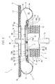
FIG. 1 is a longitudinal cross-sectional view of an air spring apparatus related to an embodiment of the present invention. -
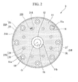
FIG. 2 is a top view of a plate-like base section that forms the air spring apparatus shown inFIG. 1 . -
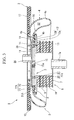
FIG. 3 is a longitudinal cross-sectional view of an exhaust state in which the interior of the diaphragm is exhausted in the air spring apparatus shown inFIG. 1 . - Hereinafter, an air spring apparatus related to an embodiment of the present invention will be described with reference to the drawings.
As shown inFIG. 1 , anair spring apparatus 1 includes a diaphragm 5 that includes an upper surface plate (an upper member) 2, a lower surface plate (a lower member) 3, and acylindrical membrane member 4 havingopen end sections surface plates intermediate portion 4c located between theopen end sections lower surface plate 3 of the diaphragm 5. Theair spring apparatus 1 is provided, for example, between a body and a carriage (not shown) of a railroad vehicle or the like. - The auxiliary elastic body 6 is formed in a cylindrical shape, and respective central axial lines of the
upper surface plate 2, thelower surface plate 3, thecylindrical membrane member 4, and the auxiliary elastic body 6 are located on a common axial line.
Hereinbelow, the common axis is assumed to be an axial line O, theupper surface plate 2 side along the axial line O is assumed to be an upper side, thelower surface plate 3 side is assumed to be a lower side, a direction perpendicular to the axial line O is assumed to be a radial direction, and a direction rotating around the axial line O is assumed to be a circumferential direction. - Spring constants of the auxiliary elastic body 6 in each of the axial line O direction and the radial direction are higher than those of the diaphragm 5 in which a gas such as air is filled. In the present embodiment, the auxiliary elastic body 6 is constituted by laminated rubber that includes an annular lower board 7, an annular
upper board 8, and anannular rubber plate 9 and an annularmetallic plate 10 that are alternately disposed in the axial line O direction between theboards 7 and 8. The lower board 7, theupper board 8, therubber plate 9, and themetallic plate 10 are disposed coaxially with the axial line O. The lower board 7, theupper board 8, themetallic plate 10 and therubber plate 9 are affixed by vulcanization. - Furthermore, in the present embodiment, among outer diameters of each member that constitutes the auxiliary elastic body 6, an outer diameter of the
upper board 8 is the greatest, and the outer circumferential edge section of theupper board 8 protrudes outward in the radial direction.
Additionally, among inner diameters of each member that constitutes the auxiliary elastic body 6, the inner diameter of the lower board 7 is the smallest, and the inner circumferential edge section of the lower board 7 protrudes inward in the radial direction. - Moreover, a
communication cylinder section 7a, the interior of which is opened toward both sides in the axial line O direction to communicate with the interior of the auxiliary elastic body 6, is fitted into the lower board 7. Air supplying member, an auxiliary tank or the like (not shown) for supplying and discharging the gas such as air into and from the diaphragm 5 is hermetically connected to a portion that protrudes downward from the lower board 7 in thecommunication cylinder section 7a. - The
lower surface plate 3 of the diaphragm 5 includes a resin plate section (contact section) 11 formed of a resin material, and asupport section 12 that supports theresin plate section 11 from the lower side (the exterior of the diaphragm disposed in the axial line direction). Theresin plate section 11 and thesupport section 12 are disposed coaxially with the axial line O.
Thesupport section 12 is formed of, for example, a metallic material or the like. In the present embodiment, thesupport section 12 is configured so that a large-diameter portion 12a and a small-diameter portion 12b disposed coaxially with the axial line O are connected to each other from the lower side (the exterior) in the axial line O direction in this sequence. An outer diameter of the large-diameter portion 12a of thesupport section 12 is smaller than an outer diameter of theupper board 8 of the auxiliary elastic body 6. - Furthermore, the
support section 12 is fixed to theupper board 8 of the auxiliary elastic body 6 by a fixingbolt 13. Thus, thelower surface plate 3 and the auxiliary elastic body 6 are hermetically connected to each other, and the communication between the interior and the exterior of the auxiliary elastic body 6 through the gap between thelower surface plate 3 and the auxiliary elastic body 6 is blocked. - In addition, the
support section 12 is formed with a plurality of bolt holes 14 through which the fixingbolts 13 are inserted. The bolt holes 14 penetrate thesupport section 12 in the axial line O direction, and are disposed at intervals in the circumferential direction in a plural number, as shown inFIG. 2 . The plurality of bolt holes 14 are disposed at equal intervals in a circumferential direction on the same circle around the axial line O in the top view as viewed from the upper side in the axial line O direction. - Furthermore, as shown in
FIG 1 , in thesupport section 12, a supplying and discharginghole 15 communicating the interior of the auxiliary elastic body 6 and the interior of the diaphragm 5 penetrates in the axial line O direction. The supplying and discharginghole 15 is disposed coaxially with the axial line O, and communicates with the interior of thecommunication cylinder section 7a through the interior of the auxiliary elastic body 6.
In addition, in the shown example, afemale screw section 15a is formed in the supplying and discharginghole 15, and a hanging bolt included in a hanging device (not shown) for lifting thelower surface plate 3 upward can be screwed into thefemale screw section 15a. - In the
upper board 8 of the auxiliary elastic body 6, an outer circumferential edge section located outside thesupport section 12 in the radial direction is covered by anannular rubber seat 16 from the upper side and the outer side in the radial direction. The inner circumferential edge of therubber seat 16 is interposed between thesupport section 12 of thelower surface plate 3 and theupper board 8 of the auxiliary elastic body 6. - The lower surface of the
resin plate section 11 comes into surface contact with the upper surface of thesupport section 12. Furthermore, the outer diameter of theresin plate section 11 is equal to the outer diameter of the large-diameter portion 12a of thesupport section 12. Theresin plate section 11 is thinner than thesupport section 12 in the axial line O direction. Furthermore, in theresin plate section 11, at a position corresponding to thebolt hole 14 of thesupport section 12, aninsertion hole 11a, which is coaxial with thebolt hole 14 and has the same shape and the same size as viewed from the upper surface, is formed. Furthermore, in theresin plate section 11, at a position corresponding to the supplying and discharginghole 15 of thesupport section 12, acommunication hole 11b, which has a greater diameter than the supplying and discharginghole 15 and communicates with the supplying and discharginghole 15 and the interior of the diaphragm 5, is formed. - In addition, as the resin material for forming the
resin plate section 11, it is preferable to use a material having a lower coefficient of friction than the material for forming thesupport section 12. As the resin material, for example, a thermoplastic resin, a thermosetting resin and the like are adopted, and preferably, polyethylene, polyacetal and the like are adopted. - The
upper surface plate 2 includes a mainbody plate section 17 that has an outer diameter greater than that of thecylindrical membrane member 4, and a projecting section (contact section) 18 that projects downward (toward the interior of the diaphragm in the axial line direction) from a central section in the radial direction in the mainbody plate section 17. The mainbody plate section 17 and the projectingsection 18 are disposed coaxially with the axial line O. - The projecting
section 18 is formed in a closed-end cylindrical shape and faces theresin plate section 11 of thelower surface plate 3 in the axial line O direction. The outer diameter of the projectingsection 18 is equal to the outer diameter of theresin plate section 11.
Furthermore, in the mainbody plate section 17, an outer circumferential side portion located outside the projectingsection 18 in the radial direction is covered by anannular rubber membrane 19 from the lower side. A radial gap is provided between the projectingsection 18 and therubber membrane 19. - Additionally, the
upper surface plate 2 is provided with apenetration cylinder section 20 which penetrates the mainbody plate section 17 and the projectingsection 18 in the axial line O direction, and through which the interior and the exterior of the diaphragm 5 communicate with each other. A lower end surface of thepenetration cylinder section 20 is coplanar with the lower surface of the projectingsection 18. An upper end section of thepenetration cylinder section 20 protrudes above the mainbody plate section 17. For example, the above-mentioned gas supplying member, auxiliary tank or the like is hermetically connected to the upper end section of thepenetration cylinder section 20. - The
cylindrical membrane member 4 has flexibility, and is formed of, for example, an elastic body material, preferably, a rubber material or the like. Furthermore, the upperopen end section 4a of theopen end sections cylindrical membrane member 4 is hermetically and externally fitted to the projectingsection 18 of theupper surface plate 2, and is disposed in a gap between the projectingsection 18 and therubber membrane 19. Furthermore, the loweropen end section 4b of theopen end sections support section 12 of thelower surface plate 3, and is disposed on therubber seat 16. - Furthermore, the
intermediate portion 4c of thecylindrical membrane member 4 protrudes outward from theupper board 8 of the auxiliary elastic body 6 in the radial direction. Theintermediate portion 4c comes into contact with theupper board 8 of the auxiliary elastic body 6 from the upper side and the outer side in the radial direction via therubber seat 16 provided on thelower surface plate 3 side. Furthermore, theintermediate portion 4c comes into contact with the mainbody plate section 17 of theupper surface plate 2 from the lower side via therubber membrane 19 provided on theupper surface plate 2 side. - The projecting
section 18 of theupper surface plate 2 and theresin plate section 11 of thelower surface plate 3 are separated from each other in the axial line O direction and face each other in a filled state in which the gas is filled in the diaphragm 5. As shown inFIG. 3 , the projectingsection 18 and theresin plate section 11 slidably come into contact with each other in the exhaust state in which the interior of the diaphragm 5 is exhausted.
In the present embodiment, as shown inFIG 1 , in the diaphragm 5 of the filled state, a diaphragm space S is formed to include a central space S1 located between the projectingsection 18 of theupper surface plate 2 and theresin plate section 11 of thelower surface plate 3, and an outer circumferential space S2 which is located in thecylindrical membrane member 4, extends over the whole circumference, and is connected to the central space S1 from the outer side in the radial direction. - In the filled state, the interior of the
penetration cylinder section 20 of theupper surface plate 2 side and the supplying and discharginghole 15 of thelower surface plate 3 side communicate with the outer circumferential space S2 in thecylindrical membrane member 4 through the central space S1 between the projectingsection 18 of theupper surface plate 2 and theresin plate section 11 of thelower surface plate 3, respectively. In the filled state, for example, the gas is supplied to and discharged from the interior of thepenetration cylinder section 20 or the interior of the diaphragm 5 through the supplying and discharginghole 15, thereby adjusting the pressure in the diaphragm 5. - Furthermore, when the gas is discharged from the interior of the diaphragm 5 in the filled state through the interior of the
penetration cylinder section 20 or the supplying and discharginghole 15, the central space S1 and the outer circumferential space S2 are gradually reduced, respectively. Furthermore, the projectingsection 18 of theupper surface plate 2 and theresin plate section 11 of thelower surface plate 3 gradually approach each other in the axial line O direction. Furthermore, thecylindrical membrane member 4 gradually undergoes shrinkage deformation. Moreover, as shown inFIG. 3 , when entering the exhaust state, the projectingsection 18 and theresin plate section 11 come into contact with each other, and the central space S1 disappears.
In the exhaust state, the projectingsection 18 of theupper surface plate 2 and theresin plate section 11 of thelower surface plate 3 slide in the mutual contact state. Accordingly, theupper surface plate 2 and thelower surface plate 3 are able to relatively move in the radial direction. - Moreover, in the present embodiment, the
resin plate section 11 is provided with engagingsections resin plate section 11 with respect to thesupport section 12 by being engaged withengagement sections support section 12. - In the shown example, as the engaging
sections engagement sections section 22A having acylindrical section 23 that extends downward (the exterior of the diaphragm in the axial line direction) from the outer circumferential edge of theresin plate section 11 and is externally fitted to thesupport section 12, and afirst engagement section 21A engaged with the first engagingsection 22A are included. Furthermore, a secondengaging section 22B having acolumnar section 24 that extends downward from a portion located inside the outer circumferential edge of theresin plate section 11, and asecond engagement section 21B engaged with the second engagingsection 22B are included. - The
first engagement section 21A is formed on the outer circumferential surface of thesupport section 12 in a groove shape. In the present embodiment, thefirst engagement section 21A extends in the small-diameter portion 12b of thesupport section 12 over the whole circumference in the circumferential direction. The shape of thefirst engagement section 21 A as viewed in the longitudinal cross-section along the axial line O is a rectangular shape having side portions that extend in the axial line O direction and the radial direction. - The
cylindrical section 23 of the first engagingsection 22A is externally fitted to the small-diameter portion 12b of thesupport section 12. The outer circumferential surface of thecylindrical section 23 is coplanar with the outer circumferential surface of the large-diameter portion 12a of thesupport section 12. Furthermore, thecylindrical section 23 is interposed between the small-diameter portion 12b of thesupport section 12 and the loweropen end section 4b of thecylindrical membrane member 4.
On an inner circumferential surface of thecylindrical section 23, aprotrusion section 25 disposed in thefirst engagement section 21A protrudes inward in the radial direction. Theprotrusion section 25 is formed in an annular shape extending over the whole circumference in the circumferential direction, and theprotrusion section 25 and thefirst engagement section 21 A have the same shape and the same size. - According to the first engaging
section 22A and thefirst engagement section 21A described above, thecylindrical section 23 of the first engagingsection 22A is externally fitted to thesupport section 12. For this reason, it is possible to control the relative movement between theresin plate section 11 and thesupport section 12 in the radial direction by the contact between the inner circumferential surface of thecylindrical section 23 and the outer circumferential surface of thesupport section 12.
Furthermore, theprotrusion section 25 of the first engagingsection 22A is disposed in thefirst engagement section 21A. For this reason, it is possible to control the relative movement between theresin plate section 11 and thesupport section 12 in the axial line O direction by the contact between theprotrusion section 25 and the inner surface of thefirst engagement section 21A. - The
second engagement section 21B includes a throughhole 26 that penetrates through thesupport section 12 in the axial line O direction, and an engagingconcave section 27 that is formed on an inner circumferential surface of the throughhole 26.
As shown inFIG. 2 , a plurality of throughholes 26 are disposed inside thebolt hole 14 in thesupport section 12 in the radial direction at intervals in the circumferential direction. The plurality of throughholes 26 are disposed on the same circle around the axial line O at equal intervals in the circumferential direction, when viewed from the upper surface.
Furthermore, the engagingconcave section 27 is formed on the inner circumferential surface of the throughholes 26 over the whole circumference in a groove shape, and opens toward the lower surface of thesupport section 12 as shown inFIG. 1 . The shape of the engagingconcave section 27 as viewed in the longitudinal cross-section is a rectangular shape having each side section that extends in the axial line O direction and the radial direction. - A plurality of
columnar sections 24 of the second engagingsection 22B are disposed in the circumferential direction at intervals, and are inserted into each throughhole 26. The through holes 26 and thecolumnar sections 24 inserted into the throughholes 26 have the same shape and the same size.
Each of thecolumnar sections 24 is provided with an engagingconvex section 28 that is disposed in the engagingconcave section 27 of thesecond engagement section 21B. The engagingconvex section 28 is formed in an annular shape extending on the outer circumferential surface of thecolumnar section 24 over the whole circumference. Furthermore, the engagingconvex section 28 and the engagingconcave section 27 have the same shape and the same size. - According to the second engaging
section 22B and thesecond engagement section 21B mentioned above, thecolumnar section 24 of the second engagingsection 22B is inserted into the throughhole 26 of thesecond engagement section 21B. For this reason, it is possible to control the relative movement between theresin plate section 11 and thesupport section 12 in the radial direction by the contact between thecolumnar section 24 and the inner circumferential surface of the throughhole 26. - Furthermore, the second
engaging sections 22B and thesecond engagement sections 21B are respectively provided in plural numbers. For this reason, the plurality ofcolumnar sections 24 and the inner circumferential surfaces of the throughholes 26 come into contact with one another, and thus it is possible to control the relative movement between theresin plate section 11 and thesupport section 12 in the circumferential direction.
Furthermore, the engagingconvex section 28 of the second engagingsection 22B is disposed in the engagingconcave section 27 of thesecond engagement section 21B. For this reason, it is possible to control the relative movement between theresin plate section 11 and thesupport section 12 in the axial line O direction by the contact between the engagingconvex section 28 and the inner surface of the engagingconcave section 27. - Both the first engaging
section 22A and the second engagingsection 22B are made of the same resin material as theresin plate section 11, and are integrally provided in theresin plate section 11. A connectedbody 29 of both of the engagingsections resin plate section 11 is integrally molded by injection molding. In the present embodiment, the connectedbody 29 is integrally molded by insert molding in which the resin material is injected into a metal mold to mold the connectedbody 29, in the state in which thesupport section 12 is disposed in the metal mold (not shown). Moreover, by molding the connectedbody 29 through the insert molding, a portion in the connectedbody 29 coming into contact with thesupport section 12 comes into close contact with thesupport section 12 over approximately the entire surface. - As described above, according to the
air spring apparatus 1 related to the present embodiment, the engagingsections resin plate section 11. For this reason, the engagingsections engagement sections resin plate section 11 with respect to thesupport section 12 in each of the axial line O direction and the radial direction. As a result, when theresin plate section 11 and the projectingsection 18 of theupper surface plate 2 slide in the mutual contact state, it is possible to suppress theresin plate section 11 from being detached from thesupport section 12. - Furthermore, by providing the
resin plate section 11 with the engagingsections resin plate section 11 and thesupport section 12 can be separately formed while suppressing the detachment of theresin plate section 11 from thesupport section 12. Accordingly, for example, as in the present embodiment, durability of thelower surface plate 3 can be easily secured by forming thesupport section 12 of a metallic material or the like. - Furthermore, as the resin material for forming the
resin plate section 11, for example, by adopting a material having a smaller coefficient of friction than a material for forming thesupport section 12, a coefficient of friction between theresin plate section 11 and the projectingsection 18 of theupper surface plate 2 can be effectively reduced. - Additionally, the engaging
sections resin plate section 11 and formed of the same resin material as theresin plate section 11. For this reason, it is possible to integrally mold the connectedbody 29 of the engagingsections resin plate section 11 through the injection molding or the like as in the present embodiment, and thus the connectedbody 29 can be easily formed. - Furthermore, the connected
body 29 can be integrally molded by the injection molding. For this reason, it is possible to engage the engagingsections engagement sections body 29 by adopting the insert molding or the like, as in the present embodiment, when molding the connectedbody 29. As a result, the manufacturing work of theair spring apparatus 1 can be simplified.
Additionally, when the connectedbody 29 is molded by the insert molding as in the present embodiment, the connectedbody 29 can be brought into close contact with thesupport section 12, and thus it is possible to effectively suppress theresin plate section 11 from being detached from thesupport section 12. - Furthermore, the
cylindrical section 23 of the first engagingsection 22A extends downward from the outer circumferential edge of theresin plate section 11. For this reason, as described above, the relative movement between theresin plate section 11 and thesupport section 12 in the axial line O direction can be controlled by the contact between theprotrusion section 25 of the first engagingsection 22A and the inner surface of thefirst engagement section 21A. As a result, it is possible to suppress an outer circumferential side portion including the outer circumferential edge in theresin plate section 11 from bending upward.
In addition, by repeating sliding in the state in which theresin plate section 11 and the projectingsection 18 of theupper surface plate 2 come into contact with each other, the outer circumferential side portion of theresin plate section 11 easily bends backward. For this reason, the above-mentioned effects can be more greatly achieved. - In addition, the technical scope of the present invention is not limited to the above-mentioned embodiment, but various modifications can be added within the scope that does not depart from the gist of the present invention.
- For example, in the above-mentioned embodiment, although two types of the first engaging
section 22A and thefirst engagement section 21A, and the second engagingsection 22B and thesecond engagement section 21B are included as the engagingsections engagement sections - Furthermore, the engaging
sections engagement sections - Furthermore, in the above-mentioned embodiment, although the connected
body 29 is molded by the insert molding, the embodiment is not limited thereto. For example, the connectedbody 29 and thesupport section 12 may be separately formed and then assembled.
Furthermore, in the above-mentioned embodiment, although the engagingsections resin plate section 11 and formed of the same material as theresin plate section 11, the embodiment is not limited thereto. For example, theresin plate section 11 and the engagingsections body 29 through two-color molding. - Furthermore, in the above-mentioned embodiment, although the
resin plate section 11 is provided on thelower surface plate 3 side, theresin plate section 11 may be provided on theupper surface plate 2 side and may be provided on both sides. For example, when theresin plate section 11 is provided on theupper surface plate 2 side, a configuration may be provided in which the resin plate section is supported from the upper side (the outer side of the diaphragm in the axial line direction) by the projecting section (support section) of the upper surface plate, and an engagement section that is engaged with the engaging section is provided in the projecting section.
Additionally, theupper surface plate 2 adopted as the upper member and thelower surface plate 3 adopted as the lower member are not limited to those shown in the above-mentioned embodiment.
That is, a configuration may be adopted in which contact sections slidably coming into contact with each other in the exhaust state in which the interior of the diaphragm is exhausted are provided in each of the upper member and the lower member, and at least one of the upper member and the lower member has the contact section formed of the resin material, and includes a support section that supports the contact section from the exterior of the diaphragm in the axial line direction, and an engaging section that is provided in the contact section and controls relative movement of the contact section with respect to the support section in each of the axial line direction and the radial direction by being engaged with the engagement section that is provided in the support section. - Furthermore, in the above-mentioned embodiment, although the auxiliary elastic body 6 is constituted by the laminated rubber, the auxiliary elastic body 6 may be suitably modified by other configurations in which a spring constant in each of the axial line O direction and the radial direction is higher than that of the diaphragm 5 filled with a gas. For example, a configuration may be adopted that includes a lower board, an upper board, and a cylindrical elastic member disposed between the boards and affixed to both boards by vulcanization.
Moreover, the auxiliary elastic body 6 may be excluded. In this case, thelower surface plate 3 may include a configuration that corresponds to theupper board 8 of the auxiliary elastic body 6. - In addition, the components in the above-mentioned embodiment can be suitably replaced with well-known components within the scope that does not depart from the gist of the present invention, and the modified examples may be suitably combined.
- According to the air spring apparatus related to the present invention, it is possible to suppress the contact section from being detached from the support section.
-
- 1 air spring apparatus
- 2 upper surface plate
- 3 lower surface plate
- 4 cylindrical membrane member
- 4a, 4b open end section
- 5 diaphragm
- 11 resin plate section (contact section)
- 12 support section
- 18 projecting section (contact section)
- 21A, 21B engagement section
- 22A, 22B engaging section
- 23 cylindrical section
- 25 protrusion section
Claims (3)
- An air spring apparatus comprising:a diaphragm that has an upper member, a lower member, and a cylindrical membrane member having both open end sections connected to both the upper and lower members and sealed with the upper and lower members, the upper member and the lower member being provided with contact sections that slidably come into contact with each other in an exhaust state in which the interior of the diaphragm is exhausted,wherein at least one of the upper member and the lower member having the contact sections, which are formed of a resin material, comprises:a support section that supports the contact section from the exterior of the diaphragm disposed in an axial line direction; andan engaging section that is provided in the contact section and controls respective relative movements of the contact section with respect to the support section in the axial line direction and a radial direction by being engaged with an engagement section that is provided in the support section.
- The air spring apparatus according to claim 1,
wherein the engaging section is integrally formed with the contact section formed of the same resin material as the contact section provided with the engaging section. - The air spring apparatus according to claim 1 or 2,
wherein the engagement section is formed on an outer circumferential surface of the support section in a groove shape, and
the engaging section comprises a cylindrical section that extends toward the exterior of the diaphragm disposed in the axial line direction from an outer circumferential edge of the contact section and is externally fitted to the support section, and
a protrusion section that protrudes on an inner circumferential surface of the cylindrical section and is disposed in the engagement section.
Applications Claiming Priority (2)
| Application Number | Priority Date | Filing Date | Title |
|---|---|---|---|
| JP2011040031A JP5743604B2 (en) | 2011-02-25 | 2011-02-25 | Air spring device |
| PCT/JP2012/054406 WO2012115183A1 (en) | 2011-02-25 | 2012-02-23 | Air spring apparatus |
Publications (3)
| Publication Number | Publication Date |
|---|---|
| EP2679856A1 true EP2679856A1 (en) | 2014-01-01 |
| EP2679856A4 EP2679856A4 (en) | 2016-08-17 |
| EP2679856B1 EP2679856B1 (en) | 2020-01-01 |
Family
ID=46720957
Family Applications (1)
| Application Number | Title | Priority Date | Filing Date |
|---|---|---|---|
| EP12749106.6A Active EP2679856B1 (en) | 2011-02-25 | 2012-02-23 | Air spring apparatus |
Country Status (5)
| Country | Link |
|---|---|
| EP (1) | EP2679856B1 (en) |
| JP (1) | JP5743604B2 (en) |
| CN (2) | CN103392081B (en) |
| ES (1) | ES2778856T3 (en) |
| WO (1) | WO2012115183A1 (en) |
Families Citing this family (6)
| Publication number | Priority date | Publication date | Assignee | Title |
|---|---|---|---|---|
| US9759282B2 (en) * | 2012-07-30 | 2017-09-12 | Sumitomo Electric Industries, Ltd. | Air spring |
| JP6516628B2 (en) | 2015-08-25 | 2019-05-22 | 株式会社ブリヂストン | Air spring device |
| CN109844356B (en) * | 2016-10-17 | 2021-08-10 | 住友电气工业株式会社 | Air spring and bogie |
| CN109204362A (en) * | 2017-07-04 | 2019-01-15 | 杜邦公司 | Air spring used for rail vehicle |
| CN116547035A (en) | 2020-08-28 | 2023-08-04 | 萨鲁达医疗有限公司 | Neural stimulation responsive to posture |
| JP7670470B2 (en) * | 2020-10-20 | 2025-04-30 | ニッタ化工品株式会社 | Air spring |
Family Cites Families (13)
| Publication number | Priority date | Publication date | Assignee | Title |
|---|---|---|---|---|
| JPS5684139U (en) * | 1979-12-04 | 1981-07-07 | ||
| JPH08128502A (en) * | 1994-10-31 | 1996-05-21 | Nissan Tecsys Kk | Vibrationproof frame device for loom |
| JP4358922B2 (en) * | 1999-02-09 | 2009-11-04 | 積水化学工業株式会社 | Seismic isolation device with lock device and building equipped with the seismic isolation device |
| JP4121114B2 (en) * | 2002-04-03 | 2008-07-23 | 株式会社ブリヂストン | Air spring |
| JP4714505B2 (en) * | 2005-05-25 | 2011-06-29 | 東洋ゴム工業株式会社 | Air spring |
| JP4568206B2 (en) * | 2005-10-25 | 2010-10-27 | 住友金属工業株式会社 | Pillow spring air spring |
| DE102006047882B3 (en) * | 2006-10-10 | 2007-08-02 | Rasmussen Gmbh | Pluggable connection arrangement for hose and pipe or tube, uses leaf-spring ring for latching into annular groove |
| JP5297602B2 (en) * | 2007-06-08 | 2013-09-25 | 東洋ゴム工業株式会社 | Railway vehicle suspension system |
| JP4912267B2 (en) * | 2007-09-26 | 2012-04-11 | 東洋ゴム工業株式会社 | Air spring |
| WO2009107679A1 (en) * | 2008-02-25 | 2009-09-03 | 株式会社ブリヂストン | Air spring device |
| JP2010127350A (en) | 2008-11-26 | 2010-06-10 | Toyo Tire & Rubber Co Ltd | Suspension device for vehicle |
| JP5352363B2 (en) * | 2009-07-15 | 2013-11-27 | 東洋ゴム工業株式会社 | Vehicle suspension system |
| JP5145298B2 (en) * | 2009-07-16 | 2013-02-13 | 東洋ゴム工業株式会社 | Vehicular air spring and its mounting method |
-
2011
- 2011-02-25 JP JP2011040031A patent/JP5743604B2/en active Active
-
2012
- 2012-02-23 ES ES12749106T patent/ES2778856T3/en active Active
- 2012-02-23 EP EP12749106.6A patent/EP2679856B1/en active Active
- 2012-02-23 CN CN201280010381.0A patent/CN103392081B/en active Active
- 2012-02-23 CN CN201510182108.1A patent/CN104912989B/en active Active
- 2012-02-23 WO PCT/JP2012/054406 patent/WO2012115183A1/en not_active Ceased
Also Published As
| Publication number | Publication date |
|---|---|
| CN104912989A (en) | 2015-09-16 |
| ES2778856T3 (en) | 2020-08-12 |
| CN104912989B (en) | 2017-04-05 |
| WO2012115183A1 (en) | 2012-08-30 |
| EP2679856A4 (en) | 2016-08-17 |
| EP2679856B1 (en) | 2020-01-01 |
| JP5743604B2 (en) | 2015-07-01 |
| CN103392081B (en) | 2015-08-26 |
| JP2012177407A (en) | 2012-09-13 |
| CN103392081A (en) | 2013-11-13 |
Similar Documents
| Publication | Publication Date | Title |
|---|---|---|
| EP2679856B1 (en) | Air spring apparatus | |
| US9868261B2 (en) | Vent piece, tire vulcanization mold with vent piece, and tire manufactured using tire vulcanization mold | |
| US8801453B1 (en) | Rotary connector having a housing and a locking ring | |
| US9285004B2 (en) | Silencer for a multi-leaf spring | |
| US11654764B2 (en) | Vibration-damping device body and vibration-damping device | |
| WO2015054282A4 (en) | Convertible plungers, film coated plungers and related syringe assemblies | |
| JP2014125079A (en) | Non-pneumatic tire | |
| EP1844978A3 (en) | Interior trim for automobile | |
| JP2014125081A (en) | Non-pneumatic tire | |
| EP3441236B1 (en) | Fastening member for use in a connection structure between an airless tire and a rim | |
| CN102822558B (en) | Anti-vibration device and manufacturing method of anti-vibration device | |
| US20140157977A1 (en) | Cylinder mechanism | |
| US10065265B2 (en) | Joined body | |
| CN112744685A (en) | Universal vacuum chuck and method of lifting an object | |
| US20120313329A1 (en) | Vented Dual Lip Seal And Method Of Making | |
| US20160053804A1 (en) | Dust cover for ball joint | |
| EP2236867A1 (en) | Sealing Device | |
| US20140339749A1 (en) | Anti-vibration device | |
| WO2012105444A1 (en) | Air spring device | |
| US20240271677A1 (en) | Vibration device | |
| CN107763215A (en) | Sealing system and the valve for being provided with sealing system | |
| WO2016157967A1 (en) | Gas pressure type actuator | |
| EP2647871A1 (en) | Air spring | |
| KR20160103089A (en) | Air spring device and method for manufacturing air spring device | |
| CA2955864C (en) | Cushion pin |
Legal Events
| Date | Code | Title | Description |
|---|---|---|---|
| PUAI | Public reference made under article 153(3) epc to a published international application that has entered the european phase |
Free format text: ORIGINAL CODE: 0009012 |
|
| 17P | Request for examination filed |
Effective date: 20130829 |
|
| AK | Designated contracting states |
Kind code of ref document: A1 Designated state(s): AL AT BE BG CH CY CZ DE DK EE ES FI FR GB GR HR HU IE IS IT LI LT LU LV MC MK MT NL NO PL PT RO RS SE SI SK SM TR |
|
| DAX | Request for extension of the european patent (deleted) | ||
| RA4 | Supplementary search report drawn up and despatched (corrected) |
Effective date: 20160720 |
|
| RIC1 | Information provided on ipc code assigned before grant |
Ipc: F16F 9/05 20060101ALI20160714BHEP Ipc: F16F 13/00 20060101ALI20160714BHEP Ipc: F16F 15/04 20060101ALI20160714BHEP Ipc: B61F 5/10 20060101ALI20160714BHEP Ipc: F16F 9/32 20060101ALI20160714BHEP Ipc: B61F 5/02 20060101ALI20160714BHEP Ipc: F16F 9/08 20060101AFI20160714BHEP |
|
| GRAP | Despatch of communication of intention to grant a patent |
Free format text: ORIGINAL CODE: EPIDOSNIGR1 |
|
| STAA | Information on the status of an ep patent application or granted ep patent |
Free format text: STATUS: GRANT OF PATENT IS INTENDED |
|
| INTG | Intention to grant announced |
Effective date: 20190724 |
|
| GRAS | Grant fee paid |
Free format text: ORIGINAL CODE: EPIDOSNIGR3 |
|
| GRAA | (expected) grant |
Free format text: ORIGINAL CODE: 0009210 |
|
| STAA | Information on the status of an ep patent application or granted ep patent |
Free format text: STATUS: THE PATENT HAS BEEN GRANTED |
|
| AK | Designated contracting states |
Kind code of ref document: B1 Designated state(s): AL AT BE BG CH CY CZ DE DK EE ES FI FR GB GR HR HU IE IS IT LI LT LU LV MC MK MT NL NO PL PT RO RS SE SI SK SM TR |
|
| REG | Reference to a national code |
Ref country code: GB Ref legal event code: FG4D |
|
| REG | Reference to a national code |
Ref country code: CH Ref legal event code: EP Ref country code: AT Ref legal event code: REF Ref document number: 1220151 Country of ref document: AT Kind code of ref document: T Effective date: 20200115 |
|
| REG | Reference to a national code |
Ref country code: IE Ref legal event code: FG4D |
|
| REG | Reference to a national code |
Ref country code: DE Ref legal event code: R096 Ref document number: 602012066915 Country of ref document: DE |
|
| REG | Reference to a national code |
Ref country code: NL Ref legal event code: MP Effective date: 20200101 |
|
| REG | Reference to a national code |
Ref country code: LT Ref legal event code: MG4D |
|
| PG25 | Lapsed in a contracting state [announced via postgrant information from national office to epo] |
Ref country code: NL Free format text: LAPSE BECAUSE OF FAILURE TO SUBMIT A TRANSLATION OF THE DESCRIPTION OR TO PAY THE FEE WITHIN THE PRESCRIBED TIME-LIMIT Effective date: 20200101 Ref country code: RS Free format text: LAPSE BECAUSE OF FAILURE TO SUBMIT A TRANSLATION OF THE DESCRIPTION OR TO PAY THE FEE WITHIN THE PRESCRIBED TIME-LIMIT Effective date: 20200101 Ref country code: NO Free format text: LAPSE BECAUSE OF FAILURE TO SUBMIT A TRANSLATION OF THE DESCRIPTION OR TO PAY THE FEE WITHIN THE PRESCRIBED TIME-LIMIT Effective date: 20200401 Ref country code: FI Free format text: LAPSE BECAUSE OF FAILURE TO SUBMIT A TRANSLATION OF THE DESCRIPTION OR TO PAY THE FEE WITHIN THE PRESCRIBED TIME-LIMIT Effective date: 20200101 Ref country code: PT Free format text: LAPSE BECAUSE OF FAILURE TO SUBMIT A TRANSLATION OF THE DESCRIPTION OR TO PAY THE FEE WITHIN THE PRESCRIBED TIME-LIMIT Effective date: 20200527 Ref country code: CZ Free format text: LAPSE BECAUSE OF FAILURE TO SUBMIT A TRANSLATION OF THE DESCRIPTION OR TO PAY THE FEE WITHIN THE PRESCRIBED TIME-LIMIT Effective date: 20200101 Ref country code: LT Free format text: LAPSE BECAUSE OF FAILURE TO SUBMIT A TRANSLATION OF THE DESCRIPTION OR TO PAY THE FEE WITHIN THE PRESCRIBED TIME-LIMIT Effective date: 20200101 |
|
| REG | Reference to a national code |
Ref country code: ES Ref legal event code: FG2A Ref document number: 2778856 Country of ref document: ES Kind code of ref document: T3 Effective date: 20200812 |
|
| PG25 | Lapsed in a contracting state [announced via postgrant information from national office to epo] |
Ref country code: LV Free format text: LAPSE BECAUSE OF FAILURE TO SUBMIT A TRANSLATION OF THE DESCRIPTION OR TO PAY THE FEE WITHIN THE PRESCRIBED TIME-LIMIT Effective date: 20200101 Ref country code: SE Free format text: LAPSE BECAUSE OF FAILURE TO SUBMIT A TRANSLATION OF THE DESCRIPTION OR TO PAY THE FEE WITHIN THE PRESCRIBED TIME-LIMIT Effective date: 20200101 Ref country code: BG Free format text: LAPSE BECAUSE OF FAILURE TO SUBMIT A TRANSLATION OF THE DESCRIPTION OR TO PAY THE FEE WITHIN THE PRESCRIBED TIME-LIMIT Effective date: 20200401 Ref country code: GR Free format text: LAPSE BECAUSE OF FAILURE TO SUBMIT A TRANSLATION OF THE DESCRIPTION OR TO PAY THE FEE WITHIN THE PRESCRIBED TIME-LIMIT Effective date: 20200402 Ref country code: IS Free format text: LAPSE BECAUSE OF FAILURE TO SUBMIT A TRANSLATION OF THE DESCRIPTION OR TO PAY THE FEE WITHIN THE PRESCRIBED TIME-LIMIT Effective date: 20200501 Ref country code: HR Free format text: LAPSE BECAUSE OF FAILURE TO SUBMIT A TRANSLATION OF THE DESCRIPTION OR TO PAY THE FEE WITHIN THE PRESCRIBED TIME-LIMIT Effective date: 20200101 |
|
| REG | Reference to a national code |
Ref country code: CH Ref legal event code: PL |
|
| REG | Reference to a national code |
Ref country code: DE Ref legal event code: R097 Ref document number: 602012066915 Country of ref document: DE |
|
| REG | Reference to a national code |
Ref country code: BE Ref legal event code: MM Effective date: 20200229 |
|
| PG25 | Lapsed in a contracting state [announced via postgrant information from national office to epo] |
Ref country code: SM Free format text: LAPSE BECAUSE OF FAILURE TO SUBMIT A TRANSLATION OF THE DESCRIPTION OR TO PAY THE FEE WITHIN THE PRESCRIBED TIME-LIMIT Effective date: 20200101 Ref country code: EE Free format text: LAPSE BECAUSE OF FAILURE TO SUBMIT A TRANSLATION OF THE DESCRIPTION OR TO PAY THE FEE WITHIN THE PRESCRIBED TIME-LIMIT Effective date: 20200101 Ref country code: SK Free format text: LAPSE BECAUSE OF FAILURE TO SUBMIT A TRANSLATION OF THE DESCRIPTION OR TO PAY THE FEE WITHIN THE PRESCRIBED TIME-LIMIT Effective date: 20200101 Ref country code: DK Free format text: LAPSE BECAUSE OF FAILURE TO SUBMIT A TRANSLATION OF THE DESCRIPTION OR TO PAY THE FEE WITHIN THE PRESCRIBED TIME-LIMIT Effective date: 20200101 Ref country code: LU Free format text: LAPSE BECAUSE OF NON-PAYMENT OF DUE FEES Effective date: 20200223 Ref country code: MC Free format text: LAPSE BECAUSE OF FAILURE TO SUBMIT A TRANSLATION OF THE DESCRIPTION OR TO PAY THE FEE WITHIN THE PRESCRIBED TIME-LIMIT Effective date: 20200101 Ref country code: RO Free format text: LAPSE BECAUSE OF FAILURE TO SUBMIT A TRANSLATION OF THE DESCRIPTION OR TO PAY THE FEE WITHIN THE PRESCRIBED TIME-LIMIT Effective date: 20200101 |
|
| PLBE | No opposition filed within time limit |
Free format text: ORIGINAL CODE: 0009261 |
|
| STAA | Information on the status of an ep patent application or granted ep patent |
Free format text: STATUS: NO OPPOSITION FILED WITHIN TIME LIMIT |
|
| REG | Reference to a national code |
Ref country code: AT Ref legal event code: MK05 Ref document number: 1220151 Country of ref document: AT Kind code of ref document: T Effective date: 20200101 |
|
| PG25 | Lapsed in a contracting state [announced via postgrant information from national office to epo] |
Ref country code: LI Free format text: LAPSE BECAUSE OF NON-PAYMENT OF DUE FEES Effective date: 20200229 Ref country code: CH Free format text: LAPSE BECAUSE OF NON-PAYMENT OF DUE FEES Effective date: 20200229 |
|
| 26N | No opposition filed |
Effective date: 20201002 |
|
| PG25 | Lapsed in a contracting state [announced via postgrant information from national office to epo] |
Ref country code: IE Free format text: LAPSE BECAUSE OF NON-PAYMENT OF DUE FEES Effective date: 20200223 Ref country code: IT Free format text: LAPSE BECAUSE OF FAILURE TO SUBMIT A TRANSLATION OF THE DESCRIPTION OR TO PAY THE FEE WITHIN THE PRESCRIBED TIME-LIMIT Effective date: 20200101 Ref country code: AT Free format text: LAPSE BECAUSE OF FAILURE TO SUBMIT A TRANSLATION OF THE DESCRIPTION OR TO PAY THE FEE WITHIN THE PRESCRIBED TIME-LIMIT Effective date: 20200101 Ref country code: FR Free format text: LAPSE BECAUSE OF NON-PAYMENT OF DUE FEES Effective date: 20200301 |
|
| PG25 | Lapsed in a contracting state [announced via postgrant information from national office to epo] |
Ref country code: SI Free format text: LAPSE BECAUSE OF FAILURE TO SUBMIT A TRANSLATION OF THE DESCRIPTION OR TO PAY THE FEE WITHIN THE PRESCRIBED TIME-LIMIT Effective date: 20200101 Ref country code: PL Free format text: LAPSE BECAUSE OF FAILURE TO SUBMIT A TRANSLATION OF THE DESCRIPTION OR TO PAY THE FEE WITHIN THE PRESCRIBED TIME-LIMIT Effective date: 20200101 Ref country code: BE Free format text: LAPSE BECAUSE OF NON-PAYMENT OF DUE FEES Effective date: 20200229 |
|
| GBPC | Gb: european patent ceased through non-payment of renewal fee |
Effective date: 20200401 |
|
| PG25 | Lapsed in a contracting state [announced via postgrant information from national office to epo] |
Ref country code: GB Free format text: LAPSE BECAUSE OF NON-PAYMENT OF DUE FEES Effective date: 20200401 |
|
| PG25 | Lapsed in a contracting state [announced via postgrant information from national office to epo] |
Ref country code: TR Free format text: LAPSE BECAUSE OF FAILURE TO SUBMIT A TRANSLATION OF THE DESCRIPTION OR TO PAY THE FEE WITHIN THE PRESCRIBED TIME-LIMIT Effective date: 20200101 Ref country code: MT Free format text: LAPSE BECAUSE OF FAILURE TO SUBMIT A TRANSLATION OF THE DESCRIPTION OR TO PAY THE FEE WITHIN THE PRESCRIBED TIME-LIMIT Effective date: 20200101 Ref country code: CY Free format text: LAPSE BECAUSE OF FAILURE TO SUBMIT A TRANSLATION OF THE DESCRIPTION OR TO PAY THE FEE WITHIN THE PRESCRIBED TIME-LIMIT Effective date: 20200101 |
|
| PG25 | Lapsed in a contracting state [announced via postgrant information from national office to epo] |
Ref country code: MK Free format text: LAPSE BECAUSE OF FAILURE TO SUBMIT A TRANSLATION OF THE DESCRIPTION OR TO PAY THE FEE WITHIN THE PRESCRIBED TIME-LIMIT Effective date: 20200101 Ref country code: AL Free format text: LAPSE BECAUSE OF FAILURE TO SUBMIT A TRANSLATION OF THE DESCRIPTION OR TO PAY THE FEE WITHIN THE PRESCRIBED TIME-LIMIT Effective date: 20200101 |
|
| PGFP | Annual fee paid to national office [announced via postgrant information from national office to epo] |
Ref country code: ES Payment date: 20220426 Year of fee payment: 11 |
|
| REG | Reference to a national code |
Ref country code: ES Ref legal event code: PC2A Owner name: PROSPIRA CORPORATION Effective date: 20220819 |
|
| REG | Reference to a national code |
Ref country code: DE Ref legal event code: R081 Ref document number: 602012066915 Country of ref document: DE Owner name: PROSPIRA CORPORATION, JP Free format text: FORMER OWNER: BRIDGESTONE CORPORATION, TOKYO, JP |
|
| REG | Reference to a national code |
Ref country code: DE Ref legal event code: R082 Ref document number: 602012066915 Country of ref document: DE |
|
| PG25 | Lapsed in a contracting state [announced via postgrant information from national office to epo] |
Ref country code: ES Free format text: LAPSE BECAUSE OF NON-PAYMENT OF DUE FEES Effective date: 20230224 |
|
| REG | Reference to a national code |
Ref country code: ES Ref legal event code: FD2A Effective date: 20240426 |
|
| PG25 | Lapsed in a contracting state [announced via postgrant information from national office to epo] |
Ref country code: ES Free format text: LAPSE BECAUSE OF NON-PAYMENT OF DUE FEES Effective date: 20230224 |
|
| PGFP | Annual fee paid to national office [announced via postgrant information from national office to epo] |
Ref country code: DE Payment date: 20240219 Year of fee payment: 13 |
|
| REG | Reference to a national code |
Ref country code: DE Ref legal event code: R119 Ref document number: 602012066915 Country of ref document: DE |
|
| PG25 | Lapsed in a contracting state [announced via postgrant information from national office to epo] |
Ref country code: DE Free format text: LAPSE BECAUSE OF NON-PAYMENT OF DUE FEES Effective date: 20250902 |