EP3441236B1 - Fastening member for use in a connection structure between an airless tire and a rim - Google Patents
Fastening member for use in a connection structure between an airless tire and a rim Download PDFInfo
- Publication number
- EP3441236B1 EP3441236B1 EP18188599.7A EP18188599A EP3441236B1 EP 3441236 B1 EP3441236 B1 EP 3441236B1 EP 18188599 A EP18188599 A EP 18188599A EP 3441236 B1 EP3441236 B1 EP 3441236B1
- Authority
- EP
- European Patent Office
- Prior art keywords
- tire
- rim
- fastening member
- extension section
- column body
- Prior art date
- Legal status (The legal status is an assumption and is not a legal conclusion. Google has not performed a legal analysis and makes no representation as to the accuracy of the status listed.)
- Not-in-force
Links
- 230000000694 effects Effects 0.000 description 4
- 125000006850 spacer group Chemical group 0.000 description 3
- 229910000831 Steel Inorganic materials 0.000 description 2
- 238000000034 method Methods 0.000 description 2
- 239000010959 steel Substances 0.000 description 2
- 238000010521 absorption reaction Methods 0.000 description 1
- 230000001419 dependent effect Effects 0.000 description 1
- 239000000835 fiber Substances 0.000 description 1
- 238000000465 moulding Methods 0.000 description 1
- 239000002861 polymer material Substances 0.000 description 1
- 230000035939 shock Effects 0.000 description 1
- 239000007787 solid Substances 0.000 description 1
- 229920002994 synthetic fiber Polymers 0.000 description 1
Images

Classifications
-
- B—PERFORMING OPERATIONS; TRANSPORTING
- B60—VEHICLES IN GENERAL
- B60C—VEHICLE TYRES; TYRE INFLATION; TYRE CHANGING; CONNECTING VALVES TO INFLATABLE ELASTIC BODIES IN GENERAL; DEVICES OR ARRANGEMENTS RELATED TO TYRES
- B60C7/00—Non-inflatable or solid tyres
- B60C7/24—Non-inflatable or solid tyres characterised by means for securing tyres on rim or wheel body
-
- F—MECHANICAL ENGINEERING; LIGHTING; HEATING; WEAPONS; BLASTING
- F16—ENGINEERING ELEMENTS AND UNITS; GENERAL MEASURES FOR PRODUCING AND MAINTAINING EFFECTIVE FUNCTIONING OF MACHINES OR INSTALLATIONS; THERMAL INSULATION IN GENERAL
- F16B—DEVICES FOR FASTENING OR SECURING CONSTRUCTIONAL ELEMENTS OR MACHINE PARTS TOGETHER, e.g. NAILS, BOLTS, CIRCLIPS, CLAMPS, CLIPS OR WEDGES; JOINTS OR JOINTING
- F16B21/00—Means for preventing relative axial movement of a pin, spigot, shaft or the like and a member surrounding it; Stud-and-socket releasable fastenings
- F16B21/06—Releasable fastening devices with snap-action
- F16B21/08—Releasable fastening devices with snap-action in which the stud, pin, or spigot has a resilient part
- F16B21/084—Releasable fastening devices with snap-action in which the stud, pin, or spigot has a resilient part with a series of flexible ribs or fins extending laterally from the shank of the stud, pin or spigot, said ribs or fins deforming predominantly in a direction parallel to the direction of insertion of the shank
Definitions
- the present invention relates generally to a fastening member, and more particularly to a fastening member for use in a connection structure between an airless tire and a rim.
- Chinese Patent No. 201080001376.4 discloses a technique for connecting an airless tire with the rim.
- multiple strip-shaped stopper members are inserted in a tire lip section of the airless tire and inlaid in the groove of the rim.
- Two ends of the stopper members are engaged with the inner side of the opening of the groove of the rim. Accordingly, the stopper members are engaged with the rim to locate the tire lip in the groove of the rim so as to connect the airless tire with the rim.
- the structure layers of fiber wires, steel string rings, artificial fiber strings and tire lip steel wires are used to provide sufficient strength for the tire.
- the tire contacts the ground to bear a load and rotate, the tire can keep a complete configuration so as to ensure that the tire is stably connected with the rim and ensure the safety in driving.
- the structure of such tire generally has no structure layer as the inflatable tire.
- the airless tire only has an elastic antiwear structure similar to the rubber layer of the inflatable tire for providing elasticity and shock absorption effect. Therefore, when the airless tire runs on the ground, in comparison with the inflatable tire, the ability of the airless tire to keep the configuration unchanged is obviously weaker.
- an attachment structure for fixation of a non-pneumatic tire on a bicycle rim is known.
- the tire comprises radially extending holes accommodating parts of the attachment structures, respectively.
- the attachment structure comprises a retaining member, a spacer, a first fastening member and a second fastening member - and is therefore four-parted.
- the second fastening member extends in an axial direction through the tire being inserted in a corresponding slot formed in the tire.
- the retaining member is positioned on the surface of the tire facing the rim, i.e.
- the spacer is positioned between the retaining member and the second fastening member and is arranged in one of the radially extending holes formed in the tire.
- the first fastening member is inserted in this arrangement and extends through a hole in the retaining member and through the spacer and is fixed on the second fastening member, for instance by a screw connection.
- the present invention provides a fastening member with the features defined in claim 1. Preferred embodiments thereof are presented in the dependent claims.
- the fastening member of the present invention has an extension section with a predetermined length, wherein said predetermined length corresponds to at least one half of a thickness of an annular tire body that is to be connected to a rim by the fastening member of the present invention.
- the extension section is configured to be coaxially inserted into a corresponding socket and held therein by friction force only, wherein, in use, one end of the extension section, protrudes from an opening of the socket on the inner circumference of the tire body.
- the fastening member further has a base section fixedly connected with one end of the extension section, the base section being engageable in the connection groove.
- the extension section has a column body with an outer diameter such that the column body can be tightly inserted in the socket so that the fastening member is securely connectable to an airless tire.
- the extension section may further include at least one protrusion protruding radially outwardly from the column body.
- the protrusion can engage with the wall of the corresponding socket so as to enhance the connection strength between the fastening member and the airless tire.
- the extension section may further comprise a split extending axially inwardly from a free end of the column body to divide the column body. Accordingly, in use, the column body will be temporarily contracted under an external force to reduce the outer diameter thereof. In this case, the column body can be successfully inserted into the corresponding socket with smaller inner diameter. After the external force disappears, the column body can restore to its original state with larger outer diameter and expand within the socket. Accordingly, the column body can apply a force to the wall of the socket to enhance the connection strength.
- the fastening member according to a first embodiment is used in a connection structure 10 between an airless tire and a rim, wherein said connection structure 10 includes a rim 20, an airless tire 30 and multiple fastening members 40 according to the present invention.
- the rim 20 is similar to the conventional rim, substantially having an annular rim body 21.
- An annular connection groove 22 with smaller opening is formed on outer circumference of the rim body 21.
- the airless tire 30 has a tire body 31 made of polymer material with suitable elasticity by molding. Multiple sockets 32 radially extend from inner circumference of the tire body 31 into the tire body 31 by suitable depth. Each socket 32 has an opening formed on the inner circumference of the tire body 31.
- the tire body 31 has an annular main body 311.
- An annular tire lip 312 with a certain thickness protrudes from the inner circumference of the main body 311.
- the tire lip 312 is inserted in the connection groove 22, whereby the main body 311 is annularly disposed around the rim body 21.
- Multiple recesses 313 with suitable depth are formed on the inner circumference of the tire lip 312.
- the depth of the recesses 313 is approximately equal to the thickness of the tire lip 312.
- the recesses 313 are positioned where the sockets 32 are positioned. Accordingly, the tire lip 312 is interrupted by the recesses 313 to form a discontinuous annular form.
- the openings of the sockets 32 are formed on the inner circumference of the main body 311.
- Each fastening member 40 has an extension section 41 with a certain length and a plate-shaped base section 42 perpendicularly fixedly connected with one end of the extension section 41.
- the extension section 41 is inserted in the corresponding socket 32 with one end protruding from the opening of the socket 41 on the inner circumference of the main body 311.
- the base section 42 is inlaid in the recess 313 and engaged in the connection groove 22.
- the opening of the connection groove 22 with smaller width restricts the base section 42 from detaching out of the connection groove 22 so that the base section 42 is located in the connection groove 22.
- the extension section 41 is a column body 411 with a certain diameter, such that, in use, the extension section 41 can be fixedly inserted in the socket 32 by press fit.
- One end of the column body 41 is perpendicularly fixedly connected with the base section 42, whereby the fastening member 40 can be securely connected with the tire body 31.
- the base section 42 of the fastening member 40 in the use state, is tightly engaged with the rim 20 and the extension section 41 is securely connected with the airless tire 30. Under such circumstance, the airless tire 30 is fastened to the rim 20 without easy detachment. Moreover, the extension section 41 is correspondingly inserted in the radially extending socket 32. Accordingly, the fastening member 40 is configured to provide a two-dimensional connection force between the airless tire 30 and the rim 20. To speak more specifically, in the use state, when the airless tire 30 contacts the ground to smoothly rotate, the force applied to the tire face will be uniformly distributed to every part of the airless tire 30. In this case, the airless tire 30 is uniformly deformed to absorb the force.
- the action force concentrated on one side of the tire body 31 will cause severe deformation of one side of the tire body 31.
- the extension section 41 is fixedly connected with the base section 42, the force applied to one side of the tire body 31 is partially transmitted from the base section 42 to the rim 20. Accordingly, the airless tire 30 is prevented from being over-deformed due to excessively great action force applied to a part of the airless tire 30. Therefore, the airless tire 30 is prevented from detaching from the rim 20 and can be stably connected with the rim 20.
- the length of the extension section 41 is at least one half of the thickness of the tire body 31. Therefore, the extension section 41 can extend into the tire body 31 by a depth to or over the center of the tire body 31. This can achieve better support effect.
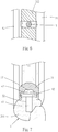
- FIGs. 8 and 9 show a second embodiment of a fastening member and the use thereof in a connection structure 10' between an airless tire and a rim.
- the second embodiment is substantially identical to the first embodiment.
- the second embodiment is different from the first embodiment in that the connection force between the extension section 41' and the socket 32' can be enhanced, since, in the second embodiment, the extension section 41' has a column body 411' and further has at least one annular protrusion 412' protruding radially outwardly from the column body 411'.
- the protrusion 412' abuts against the wall of the socket 32' so as to enhance the connection force therebetween.
- the fastening member may be also provided with multiple protrusions in the form of a reverse hook. This can further enhance the connection force between the extension section 41' and the socket 32' in the use state.
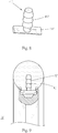
- each extension section 41" further has a split 413" extending inwardly from the other end of the column body 411" by a certain depth to divide the column body 411" Accordingly, under an external force, the column body 411" can be temporarily contracted to reduce the outer diameter thereof. In this case, the column body 411" can be successfully inserted into a corresponding socket 32" with smaller inner diameter.
- the column body 411" can restore to its original state with larger outer diameter and expand within the socket 32" Accordingly, the column body 411" can apply a force to the wall of the socket 32" to enhance the connection force therebetween. Therefore, the fastening member 40" can be more securely connected with the airless tire 30".
Landscapes
- Engineering & Computer Science (AREA)
- Mechanical Engineering (AREA)
- Tires In General (AREA)
Description
- The present invention relates generally to a fastening member, and more particularly to a fastening member for use in a connection structure between an airless tire and a rim.
- Chinese Patent No.
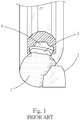
201080001376.4 - In the conventional inflatable tire structure, the structure layers of fiber wires, steel string rings, artificial fiber strings and tire lip steel wires are used to provide sufficient strength for the tire. When the tire contacts the ground to bear a load and rotate, the tire can keep a complete configuration so as to ensure that the tire is stably connected with the rim and ensure the safety in driving. With respect to an airless tire, especially a solid tire or cavity airless tire, the structure of such tire generally has no structure layer as the inflatable tire. The airless tire only has an elastic antiwear structure similar to the rubber layer of the inflatable tire for providing elasticity and shock absorption effect. Therefore, when the airless tire runs on the ground, in comparison with the inflatable tire, the ability of the airless tire to keep the configuration unchanged is obviously weaker. Therefore, when the airless tire 1 contacts the ground to run over an
obstacle 2 as shown inFig. 1 , in the case that the force applied to the airless tire 1 is greater than the engagement force between thestopper members 3 and thegroove 4, the tire lip will detach from the rim. This will affect the safety and needs to be overcome. - From the European patent application
EP 1 655 150 A1 an attachment structure for fixation of a non-pneumatic tire on a bicycle rim is known. The tire comprises radially extending holes accommodating parts of the attachment structures, respectively. The attachment structure comprises a retaining member, a spacer, a first fastening member and a second fastening member - and is therefore four-parted. The second fastening member extends in an axial direction through the tire being inserted in a corresponding slot formed in the tire. The retaining member is positioned on the surface of the tire facing the rim, i.e. on the surface of the "rim engagement portion" of the tire, and comprises a pair of elastically deformable retaining portions being in contact with the rim such that they act against a movement of the tire away from the rim, thereby holding the tire in position. The spacer is positioned between the retaining member and the second fastening member and is arranged in one of the radially extending holes formed in the tire. The first fastening member is inserted in this arrangement and extends through a hole in the retaining member and through the spacer and is fixed on the second fastening member, for instance by a screw connection. - It is therefore a primary object of the present invention to provide a fastening member configured to securely connect an airless tire with a rim in order to provide a simple connection structure between the airless tire and the rim. Further, the fastening member is configured to provide a suitable locating and support effect for the airless tire to enhance the strength thereof, such that, in use, when the airless tire contacts the ground to run over an obstacle, the airless tire is prevented from detaching from the rim so as to ensure safety in driving.
- To achieve the above and other objects, the present invention provides a fastening member with the features defined in claim 1. Preferred embodiments thereof are presented in the dependent claims.
- The fastening member of the present invention has an extension section with a predetermined length, wherein said predetermined length corresponds to at least one half of a thickness of an annular tire body that is to be connected to a rim by the fastening member of the present invention. The extension section is configured to be coaxially inserted into a corresponding socket and held therein by friction force only, wherein, in use, one end of the extension section, protrudes from an opening of the socket on the inner circumference of the tire body. The fastening member further has a base section fixedly connected with one end of the extension section, the base section being engageable in the connection groove.
- In the above fastening member, the extension section has a column body with an outer diameter such that the column body can be tightly inserted in the socket so that the fastening member is securely connectable to an airless tire.
- The extension section may further include at least one protrusion protruding radially outwardly from the column body. In use, the protrusion can engage with the wall of the corresponding socket so as to enhance the connection strength between the fastening member and the airless tire.
- The extension section may further comprise a split extending axially inwardly from a free end of the column body to divide the column body. Accordingly, in use, the column body will be temporarily contracted under an external force to reduce the outer diameter thereof. In this case, the column body can be successfully inserted into the corresponding socket with smaller inner diameter. After the external force disappears, the column body can restore to its original state with larger outer diameter and expand within the socket. Accordingly, the column body can apply a force to the wall of the socket to enhance the connection strength.
- The present invention can be best understood through the following description and accompanying drawings, wherein:
-
-
Fig. 1 is a view showing that a conventional airless air is detached from the rim when running over an obstacle; -
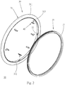
Fig. 2 is a perspective exploded view of the use of a fastening member of the present invention with an airless tire and a rim; -
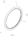
Fig. 3 is a perspective view of the assembly of a fastening member, an airless tire and a rim; -
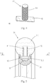
Fig. 4 is a perspective view of the fastening member of a first embodiment of the present invention; -
Fig. 5 is a sectional view taken along line 5-5 ofFig. 3 ; -
Fig. 6 is a sectional view taken along line 6-6 ofFig. 5 ; -
Fig. 7 is a sectional view showing the assembly of a fastening member, an airless tire and a rim running over an obstacle and the airless tire being deformed; -
Fig. 8 is a perspective view of the fastening member of a second embodiment of the present invention; -
Fig. 9 is a sectional view of the fastening member of the second embodiment in a use state assembled with an airless tire and a rim; -
Fig. 10 is a perspective view of the fastening member of a third embodiment of the present invention; and -
Fig. 11 is a sectional view of the fastening member of the third embodiment of the present invention in a use state assembled with an airless tire and a rim. - Please refer to
Figs. 2 to 6 . The fastening member according to a first embodiment is used in aconnection structure 10 between an airless tire and a rim, wherein saidconnection structure 10 includes arim 20, anairless tire 30 and multiple fasteningmembers 40 according to the present invention. - The
rim 20 is similar to the conventional rim, substantially having anannular rim body 21. Anannular connection groove 22 with smaller opening is formed on outer circumference of therim body 21. - The
airless tire 30 has atire body 31 made of polymer material with suitable elasticity by molding.Multiple sockets 32 radially extend from inner circumference of thetire body 31 into thetire body 31 by suitable depth. Eachsocket 32 has an opening formed on the inner circumference of thetire body 31. - To speak more specifically, the
tire body 31 has an annularmain body 311. Anannular tire lip 312 with a certain thickness protrudes from the inner circumference of themain body 311. Thetire lip 312 is inserted in theconnection groove 22, whereby themain body 311 is annularly disposed around therim body 21.Multiple recesses 313 with suitable depth are formed on the inner circumference of thetire lip 312. The depth of therecesses 313 is approximately equal to the thickness of thetire lip 312. Therecesses 313 are positioned where thesockets 32 are positioned. Accordingly, thetire lip 312 is interrupted by therecesses 313 to form a discontinuous annular form. The openings of thesockets 32 are formed on the inner circumference of themain body 311. - Each fastening
member 40 has anextension section 41 with a certain length and a plate-shapedbase section 42 perpendicularly fixedly connected with one end of theextension section 41. In use, theextension section 41 is inserted in the correspondingsocket 32 with one end protruding from the opening of thesocket 41 on the inner circumference of themain body 311. Thebase section 42 is inlaid in therecess 313 and engaged in theconnection groove 22. The opening of theconnection groove 22 with smaller width restricts thebase section 42 from detaching out of theconnection groove 22 so that thebase section 42 is located in theconnection groove 22. - The
extension section 41 is acolumn body 411 with a certain diameter, such that, in use, theextension section 41 can be fixedly inserted in thesocket 32 by press fit. One end of thecolumn body 41 is perpendicularly fixedly connected with thebase section 42, whereby thefastening member 40 can be securely connected with thetire body 31. - According to the above arrangement, in the use state, the
base section 42 of thefastening member 40 is tightly engaged with therim 20 and theextension section 41 is securely connected with theairless tire 30. Under such circumstance, theairless tire 30 is fastened to therim 20 without easy detachment. Moreover, theextension section 41 is correspondingly inserted in theradially extending socket 32. Accordingly, thefastening member 40 is configured to provide a two-dimensional connection force between theairless tire 30 and therim 20. To speak more specifically, in the use state, when theairless tire 30 contacts the ground to smoothly rotate, the force applied to the tire face will be uniformly distributed to every part of theairless tire 30. In this case, theairless tire 30 is uniformly deformed to absorb the force. When theairless tire 30 runs over an obstacle as shown inFig. 7 , the action force concentrated on one side of thetire body 31 will cause severe deformation of one side of thetire body 31. At this time, since theextension section 41 is fixedly connected with thebase section 42, the force applied to one side of thetire body 31 is partially transmitted from thebase section 42 to therim 20. Accordingly, theairless tire 30 is prevented from being over-deformed due to excessively great action force applied to a part of theairless tire 30. Therefore, theairless tire 30 is prevented from detaching from therim 20 and can be stably connected with therim 20. - Furthermore, in order to make the
fastening members 40 provide better support for theairless tire 30 in the use state, the length of theextension section 41 is at least one half of the thickness of thetire body 31. Therefore, theextension section 41 can extend into thetire body 31 by a depth to or over the center of thetire body 31. This can achieve better support effect. - Please now refer to
Figs. 8 and 9 , which show a second embodiment of a fastening member and the use thereof in a connection structure 10' between an airless tire and a rim. The second embodiment is substantially identical to the first embodiment. The second embodiment is different from the first embodiment in that the connection force between the extension section 41' and the socket 32' can be enhanced, since, in the second embodiment, the extension section 41' has a column body 411' and further has at least one annular protrusion 412' protruding radially outwardly from the column body 411'. In use, when the column body 411' is inserted into the socket 32' the protrusion 412' abuts against the wall of the socket 32' so as to enhance the connection force therebetween. - Moreover, the fastening member may be also provided with multiple protrusions in the form of a reverse hook. This can further enhance the connection force between the extension section 41' and the socket 32' in the use state.
- Please now refer to
Figs. 10 and 11 , which show a third embodiment of a fastening member and the use thereof in aconnection structure 10" between an airless tire and a rim. The third embodiment is substantially identical to the second embodiment in object and effect. However, the third embodiment is different from the second embodiment in means. In the third embodiment, eachextension section 41" further has asplit 413" extending inwardly from the other end of thecolumn body 411" by a certain depth to divide thecolumn body 411" Accordingly, under an external force, thecolumn body 411" can be temporarily contracted to reduce the outer diameter thereof. In this case, thecolumn body 411" can be successfully inserted into a correspondingsocket 32" with smaller inner diameter. After the external force disappears, thecolumn body 411" can restore to its original state with larger outer diameter and expand within thesocket 32" Accordingly, thecolumn body 411" can apply a force to the wall of thesocket 32" to enhance the connection force therebetween. Therefore, thefastening member 40" can be more securely connected with theairless tire 30".
Claims (4)
- A fastening member (40) for use with an airless tire (30) and a rim (20), wherein the rim (20) has an annular rim body (21) and defines an annular connection groove (22) on an outer circumference of the rim body (21), and wherein the airless tire (30) has an annular tire body (31) and defines multiple sockets (32) radially extending from an inner circumference of the tire body (31) into the tire body (31), the annular tire body (31) being configured for being coaxially fitted on the rim body (21), the fastening member (40) comprising:a plate-shaped base section (42) having a first end and a second end spaced from the first end by a predetermined distance, the base section (42) being configured to be engageable with the connection groove (22); andan extension section (41, 41', 41") having a column body (411, 411', 411") with a first end and a second end, wherein a predetermined length of the a column body (411, 411', 411") is defined between the first and second end, wherein the first end of the extension section (41, 41', 41") is perpendicularly fixedly connected to the base section (42) at a position between the first and second end of the base section (42), such that the column body (411, 411', 411") is perpendicularly extending outwardly from the base section (42), characterised in thatthe extension section (41, 41', 41") is configured to be coaxially insertable and tightly attachable to one of the sockets (32) by press fit,wherein the predetermined length of the extension section (41, 41', 41") is at least one half of a thickness of the annular tire body (31).
- The fastening member (40) as claimed in claim 1, wherein the extension section (41') further includes at least one protrusion (412') radially outwardly protruding from the column body (411').
- The fastening member (40) as claimed in claim 1 or 2, wherein the extension section (41") further has a split (413") axially inwardly extending from a free end of the column body (411") to divide the column body (411'').
- The fastening member (40) as claimed in claim 2 wherein the protrusion (412') is an annular protrusion disposed on the circumference of the column body (411').
Applications Claiming Priority (2)
| Application Number | Priority Date | Filing Date | Title |
|---|---|---|---|
| TW103202311U TWM483885U (en) | 2014-02-10 | 2014-02-10 | Combination structure of air-free tire and wheel rim, and fastener thereof |
| EP15150867.8A EP2905146B1 (en) | 2014-02-10 | 2015-01-13 | Connection structure between airless tire and rim and fastening members thereof |
Related Parent Applications (2)
| Application Number | Title | Priority Date | Filing Date |
|---|---|---|---|
| EP15150867.8A Division-Into EP2905146B1 (en) | 2014-02-10 | 2015-01-13 | Connection structure between airless tire and rim and fastening members thereof |
| EP15150867.8A Division EP2905146B1 (en) | 2014-02-10 | 2015-01-13 | Connection structure between airless tire and rim and fastening members thereof |
Publications (2)
| Publication Number | Publication Date |
|---|---|
| EP3441236A1 EP3441236A1 (en) | 2019-02-13 |
| EP3441236B1 true EP3441236B1 (en) | 2020-04-29 |
Family
ID=51793531
Family Applications (2)
| Application Number | Title | Priority Date | Filing Date |
|---|---|---|---|
| EP15150867.8A Not-in-force EP2905146B1 (en) | 2014-02-10 | 2015-01-13 | Connection structure between airless tire and rim and fastening members thereof |
| EP18188599.7A Not-in-force EP3441236B1 (en) | 2014-02-10 | 2015-01-13 | Fastening member for use in a connection structure between an airless tire and a rim |
Family Applications Before (1)
| Application Number | Title | Priority Date | Filing Date |
|---|---|---|---|
| EP15150867.8A Not-in-force EP2905146B1 (en) | 2014-02-10 | 2015-01-13 | Connection structure between airless tire and rim and fastening members thereof |
Country Status (12)
| Country | Link |
|---|---|
| US (1) | US9776454B2 (en) |
| EP (2) | EP2905146B1 (en) |
| JP (2) | JP3198349U (en) |
| CN (1) | CN204415055U (en) |
| DK (1) | DK2905146T3 (en) |
| ES (1) | ES2704686T3 (en) |
| HU (1) | HUE042509T2 (en) |
| LT (1) | LT2905146T (en) |
| PL (1) | PL2905146T3 (en) |
| PT (1) | PT2905146T (en) |
| TR (1) | TR201820971T4 (en) |
| TW (1) | TWM483885U (en) |
Families Citing this family (10)
| Publication number | Priority date | Publication date | Assignee | Title |
|---|---|---|---|---|
| EP3007909A4 (en) | 2013-06-15 | 2017-03-01 | Ronald Thompson | Annular ring and non-pneumatic tire |
| CN104608563A (en) * | 2014-12-25 | 2015-05-13 | 刘红伟 | Inflation-free spring type rubber tyre |
| EP3253591B1 (en) | 2015-02-04 | 2021-06-30 | Camso Inc. | Non-pneumatic tire and other annular devices |
| US11999419B2 (en) | 2015-12-16 | 2024-06-04 | Camso Inc. | Track system for traction of a vehicle |
| CN105799424A (en) * | 2016-05-16 | 2016-07-27 | 广州市耐动信息科技有限公司 | Fixed electric car tire and fixing method for tire body and wheel hub |
| DK3431306T3 (en) * | 2017-01-25 | 2020-11-16 | Tannus Co Ltd | CONNECTION UNIT |
| CN106938589A (en) * | 2017-03-20 | 2017-07-11 | 广州市耐动信息科技有限公司 | It is a kind of to be used for the wheel rim of non-inflatable tyre or pneumatic tire with back-off |
| CN113195255B (en) | 2018-11-14 | 2024-01-19 | 普利司通美国轮胎运营有限责任公司 | Tire rim assembly having inner rim component and outer rim component |
| USD909183S1 (en) * | 2019-01-30 | 2021-02-02 | Otrajet Inc. | Buckle nail |
| KR102568639B1 (en) * | 2021-05-25 | 2023-08-22 | 넥센타이어 주식회사 | Tire |
Family Cites Families (11)
| Publication number | Priority date | Publication date | Assignee | Title |
|---|---|---|---|---|
| FR321319A (en) * | 1902-05-20 | 1903-01-07 | Huffman William Scott | Improvements to tires for vehicle wheels |
| FR332619A (en) * | 1903-05-29 | 1903-11-03 | Raymond Emile Soulas | New way of fixing rubber tires for vehicle wheels, "Émile Soulas" system |
| US5040752A (en) * | 1986-10-01 | 1991-08-20 | Knoll International | Wire management clip |
| JPH11139103A (en) * | 1997-11-07 | 1999-05-25 | Nippon Mektron Ltd | Roller |
| DE10228370A1 (en) * | 2002-06-25 | 2004-01-22 | ZF Lemförder Metallwaren AG | Pendulum support made from an extruded profile |
| US7159632B2 (en) | 2004-11-08 | 2007-01-09 | Shimano Inc. | Non-pneumatic bicycle tire |
| US20070134073A1 (en) * | 2005-12-14 | 2007-06-14 | Shereyk David A | Fastener |
| DE202005020309U1 (en) * | 2005-12-27 | 2007-05-10 | S-Fasteners Gmbh | Connecting arrangement for superimposed layers of material |
| KR100943331B1 (en) | 2009-07-22 | 2010-02-19 | 화인케미칼 주식회사 | Bicycles tire |
| FR2956456B1 (en) * | 2010-02-16 | 2012-05-18 | Dinac Sa | CONNECTING ELEMENT FOR THRESHOLD BAR |
| US9610904B2 (en) * | 2012-08-13 | 2017-04-04 | Ford Global Technologies, Llc | Push pin with over-travel stop |
-
2014
- 2014-02-10 TW TW103202311U patent/TWM483885U/en not_active IP Right Cessation
-
2015
- 2015-01-13 EP EP15150867.8A patent/EP2905146B1/en not_active Not-in-force
- 2015-01-13 ES ES15150867T patent/ES2704686T3/en active Active
- 2015-01-13 PL PL15150867T patent/PL2905146T3/en unknown
- 2015-01-13 PT PT15150867T patent/PT2905146T/en unknown
- 2015-01-13 TR TR2018/20971T patent/TR201820971T4/en unknown
- 2015-01-13 EP EP18188599.7A patent/EP3441236B1/en not_active Not-in-force
- 2015-01-13 HU HUE15150867A patent/HUE042509T2/en unknown
- 2015-01-13 LT LTEP15150867.8T patent/LT2905146T/en unknown
- 2015-01-13 DK DK15150867.8T patent/DK2905146T3/en active
- 2015-01-14 US US14/596,467 patent/US9776454B2/en not_active Expired - Fee Related
- 2015-01-21 CN CN201520041330.5U patent/CN204415055U/en not_active Expired - Fee Related
- 2015-01-29 JP JP2015000387U patent/JP3198349U/en not_active Expired - Fee Related
- 2015-04-23 JP JP2015002056U patent/JP3198479U/en not_active Expired - Fee Related
Non-Patent Citations (1)
| Title |
|---|
| None * |
Also Published As
| Publication number | Publication date |
|---|---|
| JP3198349U (en) | 2015-07-02 |
| HUE042509T2 (en) | 2019-07-29 |
| ES2704686T3 (en) | 2019-03-19 |
| DK2905146T3 (en) | 2019-02-11 |
| EP2905146B1 (en) | 2018-10-17 |
| TR201820971T4 (en) | 2019-01-21 |
| PL2905146T3 (en) | 2019-04-30 |
| PT2905146T (en) | 2019-01-18 |
| US9776454B2 (en) | 2017-10-03 |
| EP2905146A3 (en) | 2016-03-09 |
| JP3198479U (en) | 2015-07-02 |
| TWM483885U (en) | 2014-08-11 |
| US20150224825A1 (en) | 2015-08-13 |
| EP2905146A2 (en) | 2015-08-12 |
| LT2905146T (en) | 2019-03-25 |
| EP3441236A1 (en) | 2019-02-13 |
| CN204415055U (en) | 2015-06-24 |
Similar Documents
| Publication | Publication Date | Title |
|---|---|---|
| EP3441236B1 (en) | Fastening member for use in a connection structure between an airless tire and a rim | |
| US10746217B2 (en) | Two-part plug-in coupling for connecting components | |
| CN106573365A (en) | Elastomeric retaining devices for joining elements | |
| EP3184832B1 (en) | Dust cover | |
| WO2011118173A1 (en) | Floor mat clip | |
| CN104819352B (en) | The circumferential connector uniformly fastened | |
| US10125803B2 (en) | Fixing device for lower level member and fluid control apparatus provided with the same | |
| US20210283966A1 (en) | Vibration-damping device body and vibration-damping device | |
| US8234952B2 (en) | Handgrip for handlebar | |
| CN105074269B (en) | Torque rod | |
| US8967337B2 (en) | Device for preventing overdrawing of winch hook | |
| CN101960185A (en) | Seals | |
| US8250714B2 (en) | Handgrip for handlebar | |
| US20140225422A1 (en) | Supporting device for a bicycle wheel | |
| CN210511541U (en) | Embedded lamp mounting device | |
| US20160153586A1 (en) | Fixing element, installation assembly, device assembly and method of fixing | |
| JP6089719B2 (en) | Dynamic damper | |
| KR101778791B1 (en) | Separation prevention washer of pressure construction | |
| JP2017187073A (en) | Fastener for pipe connection | |
| JP4932583B2 (en) | Bottle container with handle | |
| JP2017044299A (en) | Resin-made boot for slide type constant velocity joint | |
| KR101672071B1 (en) | fitting for prevention fatigue failure and separation of hose | |
| US20160131201A1 (en) | Transmission hub and sleeve assembly | |
| USD873195S1 (en) | Automotive wheel | |
| JP2010001900A (en) | Antivibration device |
Legal Events
| Date | Code | Title | Description |
|---|---|---|---|
| PUAI | Public reference made under article 153(3) epc to a published international application that has entered the european phase |
Free format text: ORIGINAL CODE: 0009012 |
|
| STAA | Information on the status of an ep patent application or granted ep patent |
Free format text: STATUS: THE APPLICATION HAS BEEN PUBLISHED |
|
| AC | Divisional application: reference to earlier application |
Ref document number: 2905146 Country of ref document: EP Kind code of ref document: P |
|
| AK | Designated contracting states |
Kind code of ref document: A1 Designated state(s): AL AT BE BG CH CY CZ DE DK EE ES FI FR GB GR HR HU IE IS IT LI LT LU LV MC MK MT NL NO PL PT RO RS SE SI SK SM TR |
|
| STAA | Information on the status of an ep patent application or granted ep patent |
Free format text: STATUS: REQUEST FOR EXAMINATION WAS MADE |
|
| 17P | Request for examination filed |
Effective date: 20190813 |
|
| RBV | Designated contracting states (corrected) |
Designated state(s): AL AT BE BG CH CY CZ DE DK EE ES FI FR GB GR HR HU IE IS IT LI LT LU LV MC MK MT NL NO PL PT RO RS SE SI SK SM TR |
|
| GRAP | Despatch of communication of intention to grant a patent |
Free format text: ORIGINAL CODE: EPIDOSNIGR1 |
|
| STAA | Information on the status of an ep patent application or granted ep patent |
Free format text: STATUS: GRANT OF PATENT IS INTENDED |
|
| INTG | Intention to grant announced |
Effective date: 20191115 |
|
| GRAS | Grant fee paid |
Free format text: ORIGINAL CODE: EPIDOSNIGR3 |
|
| GRAA | (expected) grant |
Free format text: ORIGINAL CODE: 0009210 |
|
| STAA | Information on the status of an ep patent application or granted ep patent |
Free format text: STATUS: THE PATENT HAS BEEN GRANTED |
|
| AC | Divisional application: reference to earlier application |
Ref document number: 2905146 Country of ref document: EP Kind code of ref document: P |
|
| AK | Designated contracting states |
Kind code of ref document: B1 Designated state(s): AL AT BE BG CH CY CZ DE DK EE ES FI FR GB GR HR HU IE IS IT LI LT LU LV MC MK MT NL NO PL PT RO RS SE SI SK SM TR |
|
| REG | Reference to a national code |
Ref country code: GB Ref legal event code: FG4D |
|
| REG | Reference to a national code |
Ref country code: CH Ref legal event code: EP |
|
| REG | Reference to a national code |
Ref country code: AT Ref legal event code: REF Ref document number: 1262731 Country of ref document: AT Kind code of ref document: T Effective date: 20200515 |
|
| REG | Reference to a national code |
Ref country code: DE Ref legal event code: R096 Ref document number: 602015051962 Country of ref document: DE |
|
| REG | Reference to a national code |
Ref country code: IE Ref legal event code: FG4D |
|
| REG | Reference to a national code |
Ref country code: NL Ref legal event code: FP |
|
| REG | Reference to a national code |
Ref country code: LT Ref legal event code: MG4D |
|
| PG25 | Lapsed in a contracting state [announced via postgrant information from national office to epo] |
Ref country code: GR Free format text: LAPSE BECAUSE OF FAILURE TO SUBMIT A TRANSLATION OF THE DESCRIPTION OR TO PAY THE FEE WITHIN THE PRESCRIBED TIME-LIMIT Effective date: 20200730 Ref country code: NO Free format text: LAPSE BECAUSE OF FAILURE TO SUBMIT A TRANSLATION OF THE DESCRIPTION OR TO PAY THE FEE WITHIN THE PRESCRIBED TIME-LIMIT Effective date: 20200729 Ref country code: IS Free format text: LAPSE BECAUSE OF FAILURE TO SUBMIT A TRANSLATION OF THE DESCRIPTION OR TO PAY THE FEE WITHIN THE PRESCRIBED TIME-LIMIT Effective date: 20200829 Ref country code: FI Free format text: LAPSE BECAUSE OF FAILURE TO SUBMIT A TRANSLATION OF THE DESCRIPTION OR TO PAY THE FEE WITHIN THE PRESCRIBED TIME-LIMIT Effective date: 20200429 Ref country code: LT Free format text: LAPSE BECAUSE OF FAILURE TO SUBMIT A TRANSLATION OF THE DESCRIPTION OR TO PAY THE FEE WITHIN THE PRESCRIBED TIME-LIMIT Effective date: 20200429 Ref country code: PT Free format text: LAPSE BECAUSE OF FAILURE TO SUBMIT A TRANSLATION OF THE DESCRIPTION OR TO PAY THE FEE WITHIN THE PRESCRIBED TIME-LIMIT Effective date: 20200831 Ref country code: SE Free format text: LAPSE BECAUSE OF FAILURE TO SUBMIT A TRANSLATION OF THE DESCRIPTION OR TO PAY THE FEE WITHIN THE PRESCRIBED TIME-LIMIT Effective date: 20200429 |
|
| REG | Reference to a national code |
Ref country code: AT Ref legal event code: MK05 Ref document number: 1262731 Country of ref document: AT Kind code of ref document: T Effective date: 20200429 |
|
| PG25 | Lapsed in a contracting state [announced via postgrant information from national office to epo] |
Ref country code: BG Free format text: LAPSE BECAUSE OF FAILURE TO SUBMIT A TRANSLATION OF THE DESCRIPTION OR TO PAY THE FEE WITHIN THE PRESCRIBED TIME-LIMIT Effective date: 20200729 Ref country code: RS Free format text: LAPSE BECAUSE OF FAILURE TO SUBMIT A TRANSLATION OF THE DESCRIPTION OR TO PAY THE FEE WITHIN THE PRESCRIBED TIME-LIMIT Effective date: 20200429 Ref country code: HR Free format text: LAPSE BECAUSE OF FAILURE TO SUBMIT A TRANSLATION OF THE DESCRIPTION OR TO PAY THE FEE WITHIN THE PRESCRIBED TIME-LIMIT Effective date: 20200429 Ref country code: LV Free format text: LAPSE BECAUSE OF FAILURE TO SUBMIT A TRANSLATION OF THE DESCRIPTION OR TO PAY THE FEE WITHIN THE PRESCRIBED TIME-LIMIT Effective date: 20200429 |
|
| PG25 | Lapsed in a contracting state [announced via postgrant information from national office to epo] |
Ref country code: AL Free format text: LAPSE BECAUSE OF FAILURE TO SUBMIT A TRANSLATION OF THE DESCRIPTION OR TO PAY THE FEE WITHIN THE PRESCRIBED TIME-LIMIT Effective date: 20200429 |
|
| PG25 | Lapsed in a contracting state [announced via postgrant information from national office to epo] |
Ref country code: EE Free format text: LAPSE BECAUSE OF FAILURE TO SUBMIT A TRANSLATION OF THE DESCRIPTION OR TO PAY THE FEE WITHIN THE PRESCRIBED TIME-LIMIT Effective date: 20200429 Ref country code: AT Free format text: LAPSE BECAUSE OF FAILURE TO SUBMIT A TRANSLATION OF THE DESCRIPTION OR TO PAY THE FEE WITHIN THE PRESCRIBED TIME-LIMIT Effective date: 20200429 Ref country code: SM Free format text: LAPSE BECAUSE OF FAILURE TO SUBMIT A TRANSLATION OF THE DESCRIPTION OR TO PAY THE FEE WITHIN THE PRESCRIBED TIME-LIMIT Effective date: 20200429 Ref country code: DK Free format text: LAPSE BECAUSE OF FAILURE TO SUBMIT A TRANSLATION OF THE DESCRIPTION OR TO PAY THE FEE WITHIN THE PRESCRIBED TIME-LIMIT Effective date: 20200429 Ref country code: ES Free format text: LAPSE BECAUSE OF FAILURE TO SUBMIT A TRANSLATION OF THE DESCRIPTION OR TO PAY THE FEE WITHIN THE PRESCRIBED TIME-LIMIT Effective date: 20200429 Ref country code: CZ Free format text: LAPSE BECAUSE OF FAILURE TO SUBMIT A TRANSLATION OF THE DESCRIPTION OR TO PAY THE FEE WITHIN THE PRESCRIBED TIME-LIMIT Effective date: 20200429 Ref country code: RO Free format text: LAPSE BECAUSE OF FAILURE TO SUBMIT A TRANSLATION OF THE DESCRIPTION OR TO PAY THE FEE WITHIN THE PRESCRIBED TIME-LIMIT Effective date: 20200429 |
|
| REG | Reference to a national code |
Ref country code: DE Ref legal event code: R097 Ref document number: 602015051962 Country of ref document: DE |
|
| PG25 | Lapsed in a contracting state [announced via postgrant information from national office to epo] |
Ref country code: SK Free format text: LAPSE BECAUSE OF FAILURE TO SUBMIT A TRANSLATION OF THE DESCRIPTION OR TO PAY THE FEE WITHIN THE PRESCRIBED TIME-LIMIT Effective date: 20200429 Ref country code: PL Free format text: LAPSE BECAUSE OF FAILURE TO SUBMIT A TRANSLATION OF THE DESCRIPTION OR TO PAY THE FEE WITHIN THE PRESCRIBED TIME-LIMIT Effective date: 20200429 |
|
| PLBE | No opposition filed within time limit |
Free format text: ORIGINAL CODE: 0009261 |
|
| STAA | Information on the status of an ep patent application or granted ep patent |
Free format text: STATUS: NO OPPOSITION FILED WITHIN TIME LIMIT |
|
| 26N | No opposition filed |
Effective date: 20210201 |
|
| PG25 | Lapsed in a contracting state [announced via postgrant information from national office to epo] |
Ref country code: SI Free format text: LAPSE BECAUSE OF FAILURE TO SUBMIT A TRANSLATION OF THE DESCRIPTION OR TO PAY THE FEE WITHIN THE PRESCRIBED TIME-LIMIT Effective date: 20200429 |
|
| PG25 | Lapsed in a contracting state [announced via postgrant information from national office to epo] |
Ref country code: MC Free format text: LAPSE BECAUSE OF FAILURE TO SUBMIT A TRANSLATION OF THE DESCRIPTION OR TO PAY THE FEE WITHIN THE PRESCRIBED TIME-LIMIT Effective date: 20200429 |
|
| REG | Reference to a national code |
Ref country code: CH Ref legal event code: PL |
|
| PG25 | Lapsed in a contracting state [announced via postgrant information from national office to epo] |
Ref country code: LU Free format text: LAPSE BECAUSE OF NON-PAYMENT OF DUE FEES Effective date: 20210113 |
|
| REG | Reference to a national code |
Ref country code: BE Ref legal event code: MM Effective date: 20210131 |
|
| PG25 | Lapsed in a contracting state [announced via postgrant information from national office to epo] |
Ref country code: CH Free format text: LAPSE BECAUSE OF NON-PAYMENT OF DUE FEES Effective date: 20210131 Ref country code: LI Free format text: LAPSE BECAUSE OF NON-PAYMENT OF DUE FEES Effective date: 20210131 |
|
| PG25 | Lapsed in a contracting state [announced via postgrant information from national office to epo] |
Ref country code: IE Free format text: LAPSE BECAUSE OF NON-PAYMENT OF DUE FEES Effective date: 20210113 |
|
| PGFP | Annual fee paid to national office [announced via postgrant information from national office to epo] |
Ref country code: GB Payment date: 20220125 Year of fee payment: 8 Ref country code: DE Payment date: 20220124 Year of fee payment: 8 |
|
| PGFP | Annual fee paid to national office [announced via postgrant information from national office to epo] |
Ref country code: IT Payment date: 20220124 Year of fee payment: 8 Ref country code: FR Payment date: 20220120 Year of fee payment: 8 Ref country code: NL Payment date: 20220120 Year of fee payment: 8 |
|
| PG25 | Lapsed in a contracting state [announced via postgrant information from national office to epo] |
Ref country code: BE Free format text: LAPSE BECAUSE OF NON-PAYMENT OF DUE FEES Effective date: 20210131 |
|
| PG25 | Lapsed in a contracting state [announced via postgrant information from national office to epo] |
Ref country code: CY Free format text: LAPSE BECAUSE OF FAILURE TO SUBMIT A TRANSLATION OF THE DESCRIPTION OR TO PAY THE FEE WITHIN THE PRESCRIBED TIME-LIMIT Effective date: 20200429 |
|
| PG25 | Lapsed in a contracting state [announced via postgrant information from national office to epo] |
Ref country code: HU Free format text: LAPSE BECAUSE OF FAILURE TO SUBMIT A TRANSLATION OF THE DESCRIPTION OR TO PAY THE FEE WITHIN THE PRESCRIBED TIME-LIMIT; INVALID AB INITIO Effective date: 20150113 |
|
| REG | Reference to a national code |
Ref country code: DE Ref legal event code: R119 Ref document number: 602015051962 Country of ref document: DE |
|
| REG | Reference to a national code |
Ref country code: NL Ref legal event code: MM Effective date: 20230201 |
|
| GBPC | Gb: european patent ceased through non-payment of renewal fee |
Effective date: 20230113 |
|
| PG25 | Lapsed in a contracting state [announced via postgrant information from national office to epo] |
Ref country code: NL Free format text: LAPSE BECAUSE OF NON-PAYMENT OF DUE FEES Effective date: 20230201 Ref country code: GB Free format text: LAPSE BECAUSE OF NON-PAYMENT OF DUE FEES Effective date: 20230113 Ref country code: DE Free format text: LAPSE BECAUSE OF NON-PAYMENT OF DUE FEES Effective date: 20230801 |
|
| PG25 | Lapsed in a contracting state [announced via postgrant information from national office to epo] |
Ref country code: FR Free format text: LAPSE BECAUSE OF NON-PAYMENT OF DUE FEES Effective date: 20230131 |
|
| PG25 | Lapsed in a contracting state [announced via postgrant information from national office to epo] |
Ref country code: IT Free format text: LAPSE BECAUSE OF NON-PAYMENT OF DUE FEES Effective date: 20230113 |
|
| PG25 | Lapsed in a contracting state [announced via postgrant information from national office to epo] |
Ref country code: MK Free format text: LAPSE BECAUSE OF FAILURE TO SUBMIT A TRANSLATION OF THE DESCRIPTION OR TO PAY THE FEE WITHIN THE PRESCRIBED TIME-LIMIT Effective date: 20200429 |
|
| PG25 | Lapsed in a contracting state [announced via postgrant information from national office to epo] |
Ref country code: TR Free format text: LAPSE BECAUSE OF FAILURE TO SUBMIT A TRANSLATION OF THE DESCRIPTION OR TO PAY THE FEE WITHIN THE PRESCRIBED TIME-LIMIT Effective date: 20200429 |
|
| PG25 | Lapsed in a contracting state [announced via postgrant information from national office to epo] |
Ref country code: MT Free format text: LAPSE BECAUSE OF FAILURE TO SUBMIT A TRANSLATION OF THE DESCRIPTION OR TO PAY THE FEE WITHIN THE PRESCRIBED TIME-LIMIT Effective date: 20200429 |