EP2679490B1 - Leichtbaukufenlandewerkaufsatz - Google Patents
Leichtbaukufenlandewerkaufsatz Download PDFInfo
- Publication number
- EP2679490B1 EP2679490B1 EP12178623.0A EP12178623A EP2679490B1 EP 2679490 B1 EP2679490 B1 EP 2679490B1 EP 12178623 A EP12178623 A EP 12178623A EP 2679490 B1 EP2679490 B1 EP 2679490B1
- Authority
- EP
- European Patent Office
- Prior art keywords
- skid
- skid shoe
- assembly
- carbon fiber
- coupling
- Prior art date
- Legal status (The legal status is an assumption and is not a legal conclusion. Google has not performed a legal analysis and makes no representation as to the accuracy of the status listed.)
- Active
Links
Images

Classifications
-
- B—PERFORMING OPERATIONS; TRANSPORTING
- B64—AIRCRAFT; AVIATION; COSMONAUTICS
- B64C—AEROPLANES; HELICOPTERS
- B64C25/00—Alighting gear
- B64C25/32—Alighting gear characterised by elements which contact the ground or similar surface
- B64C25/52—Skis or runners
-
- B—PERFORMING OPERATIONS; TRANSPORTING
- B64—AIRCRAFT; AVIATION; COSMONAUTICS
- B64C—AEROPLANES; HELICOPTERS
- B64C25/00—Alighting gear
- B64C25/32—Alighting gear characterised by elements which contact the ground or similar surface
- B64C2025/325—Alighting gear characterised by elements which contact the ground or similar surface specially adapted for helicopters
Definitions
- the present disclosure generally relates to a skid shoe assembly, and more particularly, to a lightweight skid shoe assembly that may protect a structure, such as a helicopter skid tube, from friction-related damage.
- skid-type landing gear which generally comprises an assembly of horizontal skid tubes connected by support structure the fuselage of the helicopter. Skid tubes may be damaged by repeated contact and friction with landing surfaces during takeoffs, landing, and ground transport. Pads of wear-resistant metal, known as skid shoes, are typically attached to the skid tubes to protect them from damage. While they offer effective protection, traditional skid shoes are relatively heavy, which can reduce the usable load capability of a helicopter.
- US 2009/084895 A1 discloses skid shoes with wear-resistant cladding layers. Powders of hard particles and braze material are impregnated into at least one cloth which is applied to the wear surface of a skid shoe.
- CN 101092166 A discloses a helicopter crow plate type under carriage.
- the lower end of the crow plate support is connected with a rubber sole by bolt set and straw.
- US 2010/243798 A1 discloses a skid rail comprising a base member, cores and a skin, the skin being formed by a first fiber-reinforced plastic, and the cores being formed by a second fiber-reinforced plastic having fabrics of fibers having higher wear resistance than that of fibers in the first fiber-reinforced plastic.
- US 5893532 A discloses a wear surface for helicopter shoes constructed by forming a railed enclosure on a curved base plate, placing a mosaic of smooth-surfaced tungsten carbide blocks on the base plate within the enclosure, brazing the blocks to the plate and rails, and grinding the rails to form a smooth, edgeless transition between the wear surface and the plate surface.
- WO 2008/054401 A2 discloses a crash attenuation system for an aircraft, the system having an airbag carried by the aircraft and inflatable generally adjacent an exterior of the aircraft.
- Embodiments of the present disclosure generally provide lightweight skid shoe assemblies for protecting the surface of a structure such as a skid tube from friction-related damage.
- the present disclosure is directed to a lightweight skid shoe assembly comprising a body having one or more layers of wear resistant, non-metallic or partially metallic material; and a coupling mechanism for coupling the body to a skid tube; wherein the body withstands shear forces when frictionally engaging a contact surface; and wherein the body substantially prevents friction-related damage to a surface of the structure to which it is coupled.
- the material of at least one of the layers is selected from the group consisting of: a polyamide impregnated carbon fiber layup, a polyimide impregnated carbon fiber layup, a peek injection mold with carbon fiber, a polyetherimide injection mold with carbon fiber, compression molded carbon fiber, compression molded fiberglass, a resin infusion with carbon fiber preform fabric, a fiber reinforced thermoset, acetal resin, machined acetal, machined thermoplastic, thermosetting plastic, or a metal-matrix composite.
- the coupling mechanism comprises apertures in the body for receiving coupling hardware.
- the coupling mechanism comprises coupling bolts.
- the coupling mechanism comprises coupling straps.
- lightweight skid shoe assembly further comprises a shear-bearing mechanism operable to direct a portion of the shear forces away from the body when the body frictionally engages the contact surface.
- the shear-bearing mechanism comprises a retainer having an opening; and the body is disposed within the retainer.
- the depth of the opening is less than the thickness of the body.
- a portion of the body extends through the opening.
- the shear-bearing mechanism comprises a recess in the skid tube; and the body is disposed within the recess. In another embodiment, a portion of the body extends beyond the recess. In yet another embodiment, walls of the recess are operable to direct a portion of the shear forces away from the body when the body frictionally engages the contact surface.
- the body further comprises a wear indicator for determining when the body needs to be replaced.
- the body may be dispensed from a roll of body material.
- the present disclosure is directed to a lightweight skid shoe assembly
- a body having one or more layers of wear resistant, non-metallic or partially metallic material selected from the group consisting of: a polyamide impregnated carbon fiber layup, a polyimide impregnated carbon fiber layup, a peek injection mold with carbon fiber, a polyetherimide injection mold with carbon fiber, compression molded carbon fiber, compression molded fiberglass, a resin infusion with carbon fiber preform fabric, a fiber reinforced thermoset, acetal resin, machined acetal, machined thermoplastic, thermosetting plastic, or a metal-matrix composite; wherein the body substantially prevents friction-related damage to a surface of a structure to which it is coupled when the body frictionally engages a contact surface.
- the body further comprises a wear indicator for determining when the body needs to be replaced.
- lightweight skid shoe assembly further comprises a coupling mechanism for coupling the body to the structure.
- lightweight skid shoe assembly further comprises a retainer coupled to the structure; wherein the body is disposed within the retainer; and wherein the retainer is operable to direct a portion of shear forces away from the body when the body frictionally engages the contact surface.
- lightweight skid shoe assembly further comprises a recess within the structure; wherein the body is disposed within the recess; and wherein walls of the recess are operable to direct a portion of shear forces away from the body when the body frictionally engages the contact surface.
- the present disclosure is directed to a lightweight skid shoe assembly comprising a body having one or more layers of wear resistant, non-metallic or partially metallic material; and a shear-bearing mechanism within which the body is disposed; wherein the shear-bearing mechanism is operable to direct a portion of shear forces away from the body when the body frictionally engages a contact surface; and wherein the body substantially prevents friction-related damage to a surface of the structure to which it is coupled.
- Embodiments of the present disclosure generally provide a lightweight skid shoe assembly for use in a variety of applications including, but not limited to, protecting helicopter skid landing gear and other structures from friction-related damage.
- the skid shoe assembly may be lighter than traditional skid shoe assemblies, thereby reducing a helicopter's empty weight and increasing its useful load.
- lightweight skid shoe assembly may be easier to periodically replace than traditional skid shoe assemblies.
- the skid shoe assembly may comprise a skid shoe body of wear-resistant materials, all or a portion of which having sacrificial wear properties, a shear-bearing coupling mechanism to alleviate shear forces acting on the skid shoe body, and/or a recess in a protected structure within which the skid shoe body is disposed.
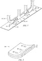
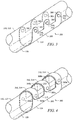
- FIGURES 1-6B illustrate representative embodiments or examples of skid shoe assemblies 100, 150, 160, 170, 180 and parts thereof. It should be understood that the components of skid shoe assemblies 100, 150, 160, 170, 180 and parts thereof shown in FIGURES 1-6B are for illustrative purposes only, and that any other suitable components or subcomponents may be used in conjunction with or in lieu of the components comprising skid shoe assemblies 100, 150, 160, 170, 180 and the parts of skid shoe assemblies 100, 150, 160, 170, 180 described herein.
- a representative skid shoe assembly 100 is shown coupled to a protected structure 110, such as a helicopter skid tube 112.
- a single skid shoe assembly 100 may generally cover a portion of, or substantially the entirety of, a protected surface 120 of the protected structure 110, such as the underside 114 of the helicopter skid tube 112, for example.
- a series of skid shoe assemblies 100 may cover a portion of, or substantially the entirety of, the protected surface 120 of the protected structure 110.
- a series of skid shoe assemblies 100 may be arranged in a spaced apart manner along the protected structure 110 to cover a portion of the protected surface 120, thereby resulting in uncovered portions 122 of the protected surface 120 and covered portions 124 of the protected surface covered by the skid shoe assemblies 100.
- the series of skid shoe assemblies 100 may further be configured to minimize or prevent contact between the uncovered portions 122 of the protected surface 120 and a contact surface 130, such as a helicopter landing pad, for example. As depicted in FIGURE 1 , one or more skid shoe assemblies 100 may be configured to protrude a suitable distance from the protected surface 120 to create a gap 125 between the uncovered portions 122 of the protected surface 120 and the contact surface 130.
- skid shoe assemblies 100 may vary in size, shape, thickness, materials, and construction. Skid shoe assemblies 100 having larger exposed areas and/or more wear-resistant constructions may be disposed on high-traffic or high-friction protected surfaces 120 or portions thereof, while skid shoe assemblies 100 having smaller exposed areas and/or less wear-resistant constructions may be disposed on lower-traffic or lower-friction protected surfaces 120 or portions thereof.
- Non-metallic constructions may offer less protection or be less durable than metallic constructions in certain applications.
- heavy-duty metallic skid shoes may still be needed under rigorous operating conditions involving numerous and/or hard landings, such as training or certification testing. It is not uncommon for helicopters to touch down and slide on a runway at speeds in excess of 60 knots during engine failure simulations, for example. Under normal operating conditions, however, operators often use medium-duty skid shoes to save weight and boost useful load as hard landings and landings on unprepared surfaces are far less common.
- Non-metallic skid shoe constructions are well suited for such conditions, as they may provide the requisite level of protection, while offering a lower weight penalty and easier replacement.
- an operator may be required to replace the skid landing gear. Many operators would view this as an acceptable cost of doing business given the relative infrequency of such events.
- the skid shoe assembly 100 may comprise a skid shoe body 200 having one or more layers 215 of lightweight, wear-resistant, non-metallic or partially metallic materials that may include, but are not limited to, a polyamide impregnated carbon fiber layup, a polyimide impregnated carbon fiber layup, a peek or PEI injection mold with carbon fiber, compression molded carbon fiber or fiberglass, a resin infusion with carbon fiber preform fabric, a fiber reinforced thermoset, acetal resin (such as DuPontTM Delrin®), machined acetal (or any wear resistant and structurally robust thermoplastic or thermosetting plastic), formed thermoplastics or thermosetting plastic, a metal-matrix composite, or any other lightweight non-metallic or partially metallic materials with sufficient capability for wear.
- a polyamide impregnated carbon fiber layup such as DuPontTM Delrin®
- machined acetal or any wear resistant and structurally robust thermoplastic or thermosetting plastic
- formed thermoplastics or thermosetting plastic such as DuPontTM Delrin®
- skid shoe body may be comprised of any number of suitable lightweight, wear-resistant, non-metallic or partially metallic materials and constructions, and the present disclosure should not be limited to only the examples provided herein.
- skid shoe body 200 may further comprise materials and/or constructions that provide for structural reinforcement.
- skid shoe body 200 may comprise injection-molded nylon with fiberglass or carbon fiber reinforcement.
- skid shoe body may comprise compression molded carbon fiber or fiberglass with one or more integral co-molded steel wear strips. All or a portion of skid shoe body 200 may have sacrificial wear properties.
- one or more layers 215 of body 200 may be classified as "sacrificial" layers, being comprised of any suitable wear-resistant material such as those described in this paragraph that may gradually wear away due to repeated frictional contact with contact surface 130. In a helicopter application, wear rate may be a function of the number of landings, any fore/aft or lateral skidding during landings, and the surface properties of the landing area.
- body 200 may comprise one or more layers 215 of lightweight, yet structurally robust material, that may be suitable to withstand all or a portion of shear loads occurring at the junction(s) of skid shoe body 200 with protected structure 110.
- Skid shoe body 200 may further comprise coupling points 300 that may be defined by flanges or apertures extending from or disposed through body 200, respectively, for coupling the layers 215 of the skid shoe body 200 together and/or for coupling the skid shoe body 200 to the protected structure 110.
- body 200 may be manufactured such that it may be disposed from a roll much like adhesive tape.
- a user may unroll a desired amount of body material from the roll and cut it to customized dimensions for coupling to the protected structure.
- an amount corresponding with a dimension of the protected surface may be dispensed.
- smaller sections may be dispensed and spaced in any suitable interval or pattern on the protected surface.
- a user may find such an embodiment beneficial for reasons including, but not limited to, less material waste, the ability to customize skid shoe dimensions, flexibility to "patch" high wear areas, and reduced cost from not having to buy custom-made skid shoes for one or more applications.
- FIGURES 3 and 4 each depict an example of a skid shoe assembly 150, 160 comprising a coupling mechanism 310 for coupling the skid shoe body 200 to a protected structure 110, such as a helicopter skid tube 112, to cover at least a portion of a protected surface 120, such as the underside 114 of the helicopter skid tube 112, for example.
- coupling mechanism 310 may react all or a portion of shear loads on the skid shoe body 200.
- coupling mechanism 310 may couple a skid shoe body 200 to a skid tube 112 and may resist fore/aft slippage of body 200 on skid tube 112 during a run-on landing.
- coupling mechanism 310 may resist lateral slippage of body 200 on skid tube 112 that would otherwise be caused by rotational movement of the skid tube 112 when flexing (spreading) under the vertical landing load of the helicopter.
- the coupling mechanism 310 of the skid shoe assembly 150 comprises a bolt 312 or a series of bolts 312 to secure the skid shoe body 200 to the helicopter skid tube 112 at discrete coupling points 300.
- the bolts 312 project through the skid shoe body 200 at coupling points 300 and into the protected structure 110, thereby securing skid shoe 200 thereon and covering a portion 124 of the protected surface 120.
- bolt 312 may have a tapered head for improved shear reaction.
- the skid shoe body 200 will make frictional, engaging contact with the contact surface 130, while generally preventing wearing engagement of the protected surface 120, 114 with the contact surface 130.
- the skid shoe body 200 With multiple helicopter landings, the skid shoe body 200 will gradually wear away due to such frictional engaging contact with the contact surface 130, and eventually, layers 215 of the skid shoe body 200, or the entire skid shoe body 200, will need to be replaced.
- the worn skid shoe body 200 may be removed by releasing the bolts 302 at the discrete contact points 300 that secure the skid shoe body 200 to the protected structure 110, 112.
- the coupling mechanism 310 of skid shoe assembly 160 comprises a strap 314 or a series of straps 314 that extend from coupling point(s) 300a located near a first edge 210 of the skid shoe body 200, then wrap around the protected structure 110, 112, and connect to corresponding coupling point(s) 300b located near a second opposing edge 212 of skid shoe body 200.
- straps 314 comprise band clamps.
- coupling mechanism 310 may comprise a collar (not shown) that may enshroud all or a portion of skid shoe body 200 and protected structure 110, thereby coupling them together and providing a mechanism to react all or a portion of shear loads acting thereon.
- collar may be heat shrinked, bonded, or mechanically fastened to protected structure 110.
- the skid shoe body 200 will make frictional, engaging contact with the contact surface 130, while generally preventing wearing engagement of the protected surface 120, 114 with the contact surface 130.
- the skid shoe body 200 will gradually wear away due to such frictional engaging contact with the contact surface 130, and eventually, layers 215 of the skid shoe body 200, or the entire skid shoe body 200, will need to be replaced.
- the worn skid shoe body 200 may be removed by releasing the straps 314 securing the skid shoe body 200 to the protected surface 110, 112.
- skid shoe bodies 200 may have inherent shear strength properties sufficient to withstand shear frictional forces associated with engaging a contact surface 130 without suffering damage or becoming dislodged. If necessary, skid shoe body 200 may comprise reinforced materials or reinforcing mechanisms (such as grommets, not shown) at coupling points 300, 300a, 300b.
- reinforced materials or reinforcing mechanisms such as grommets, not shown
- FIGURES 5A and 5B depict a bottom plan view and a side elevation view, respectively, of the present disclosure of a skid shoe assembly 170 comprising one or more shear-bearing mechanisms 400.
- Shear-bearing mechanism 400 may comprise any mechanism suitable to direct a significant portion of the shear stress on skid shoe assembly 170 away from the skid shoe body 200 and distribute such shear stress throughout the shear-bearing mechanism 400.
- the shear-bearing mechanism 400 comprises one or more retainers 410 for coupling the skid shoe body 200 to a protected surface 120, 114 of the protected structure 110, 112.
- Retainer 410 may be constructed of any suitable non-metallic, partially metallic, or metallic material and may be of any suitable planform to cover a portion of, or substantially the entirety of, skid shoe body 200.
- retainer 410 may comprise one or more openings 420 that may be substantially equal to or smaller in dimension than skid shoe body 200.
- retainer 410 may further have a thickness substantially equal to or less than the thickness of body 200.
- Retainer 410 may wrap around skid shoe body 200 and at least partially surround the protected structure 110, 112, thereby coupling the skid shoe body 200 to the protected structure 110, 112 and covering a portion 124 of the protected surface 120, 114.
- a bolt 312 or a series of bolts 312 may be used to secure the retainer 410 to the protected structure 110, 112.
- retainer 410 may be oriented relative to skid shoe body 200 such that a substantial portion of skid shoe body 200 projects through each opening 420, resulting in exposed portions 210 and unexposed portions 220 of skid shoe body 200. Such a configuration may result in the retainer 410 applying shear support to the unexposed portions 220 of skid shoe body 200, while allowing the exposed portions 210 of skid shoe body 200 to engage a contact surface 130.
- Shear-bearing coupling mechanisms 400 may be used as the sole means of coupling skid shoe body 200 to protected structure 110, 112, or in addition to other coupling mechanisms 300.
- the lower surface 217 of the exposed portions 210 of skid shoe body 200 will make frictional, engaging contact with the contact surface 130, while generally preventing wearing engagement of the protected surface 120, 114 with the contact surface 130.
- the retainer 410 will provide shear support to the unexposed portions 220 of the skid shoe body 200 during such landings.
- skid shoe body 200 may comprise a visual indicator to indicate the degree of wear and tear.
- body 200 may be imbedded with one or more colors at various depths to indicate the degree of wear.
- body 200 comprises layers 215 of different materials that may be visually distinguished from each other. When "sacrificial" layers have worn away, non-sacrificial will begin to show, indicating the need for replacement.
- the worn skid shoe body 200 may be removed by releasing the bolts 312 securing the retainer 410 to the protected surface 110, 112 and then removing the skid shoe body 200 from the retainer 410.
- layers 215 of the worn skid shoe body 200 comprising the exposed portions 210 may be removed and replaced without removing the retainer 410 by accessing such layers 215 through the opening 420 via coupling points 300 on the skid shoe body 200, as shown in FIGURE 2 .
- the abilities to accurately determine the serviceability of the shoe 100 and easily replace them are benefits of embodiments of the present disclosure as they are not generally available with traditional fully-metallic skid shoes.
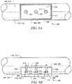
- FIGURES 6A and 6B depict a bottom plan view and a side elevation view, respectively, of another embodiment of a skid shoe assembly 180 comprising one or more shear-bearing mechanisms 400.
- the shear-bearing mechanism 400 comprises a recess 500 in the protected structure 110, 112 within which a skid shoe body 200 may be disposed.
- recess 500 may be substantially equal in planform shape and size to skid shoe body 200, and as best shown in FIGURE 6B , recess 500 may have a depth substantially equal to or less than the thickness of skid shoe body 200.
- the skid shoe body 200 may be disposed within recess 500 and coupled to one or more coupling surfaces 510 within the recess 500 by any coupling mechanism 310 suitable to secure skid shoe body 200 thereon.
- a bolt 312 or a series of bolts 312 may be used to secure the skid shoe body 200 to the coupling surfaces 510 at discrete coupling points 300.
- the coupling surfaces 510 and walls 520 of recess 500 may apply shear support to the unexposed portions 220 of skid shoe body 200, and the depth of the walls 520 may allow for exposed portions 210 of skid shoe body 200 to engage a contact surface 130.
- One having ordinary skill in the art will be capable of determining a suitable size of recess 500, as well as a suitable depth of walls 520, based on the desired amount of shear support to be provided to the unexposed portions 220 of skid shoe body 200 and the desired amount of area for exposed portions 210 of skid shoe body 200.
- the lower surface 217 of the exposed portions 210 of skid shoe body 200 will make frictional, engaging contact with the contact surface 130, while generally preventing wearing engagement of the protected surface 120, 114 with the contact surface 130.
- the walls 520 of the recess 500 will provide shear support to the unexposed portions 220 of the skid shoe body 200 during such landings.
- the exposed portions 210 of the skid shoe body 200 will gradually wear away due to such frictional engaging contact with the contact surface 130, and eventually, layers 215 of the skid shoe body 200, or the entire skid shoe body 200, will need to be replaced. Layers 215 or the entire worn skid shoe body 200 may be removed by releasing the bolts 312 securing the skid shoe body 200 to the coupling surfaces 210 and then removing the layers 215 or the entire skid shoe body 200 from the recess 500.
- Skid shoe assembly 100 may further comprise a wear skin (not shown) for protecting uncovered portions 122 of a protected surface 120.
- Wear skin may comprise a thin layer of any suitable non-metallic wear-resistant material. Wear skin may offer scratch protection from debris (rocks, gravel, sand, etc) on an unprepared landing surface.
- wear skin may be applied to uncovered portions 122 exposed by gaps 125 between skid shoe bodies 200.
- wear skin may be disposed from a roll much like adhesive tape.
- Couple and its derivatives refer to any direct or indirect communication between two or more elements, whether or not those elements are in physical contact with one another.
- the term “or” is inclusive, meaning and/or.
- the phrases “associated with” and “associated therewith,” as well as derivatives thereof, may mean to include, be included within, interconnect with, contain, be contained within, connect to or with, couple to or with, be communicable with, cooperate with, interleave, juxtapose, be proximate to, be bound to or with, have, have a property of, or the like.
Landscapes
- Engineering & Computer Science (AREA)
- Mechanical Engineering (AREA)
- Aviation & Aerospace Engineering (AREA)
- Laminated Bodies (AREA)
- Braking Arrangements (AREA)
Claims (7)
- Anordnung, umfassend:ein Kufenrohr (110, 112) für ein Hubschrauberfahrwerk (110, 112), wobei das Kufenrohr eine Aussparung (500) aufweist; undeine Kufenschuhanordnung (100), die Folgendes umfasst:wobei der Körper (200) Scherkräften widersteht, wenn er eine Kontaktfläche (130) in Reibeingriff nimmt; undeinen Körper (200), der in der Aussparung (500) angeordnet ist, wobei der Körper (200) eine oder mehrere Lagen (215) aus verschleißfestem, nichtmetallischem oder teilweise metallischem Material aufweist, wobei mindestens eine der Lagen aus verschleißfestem, nichtmetallischem oder teilweise metallischem Material eine erste Lage umfasst, und wobei die erste Lage einen Kupplungsmechanismus (310) umfasst, wobei der Kupplungsmechanismus (310) den Körper (200) mit dem Kufenrohr (110, 112) kuppelt; undeinen Scherkräfte aufnehmenden Mechanismus (400), der die Aussparung (500) in dem Kufenrohr (110, 112) umfasst und dazu fungiert, einen Teil der Scherkräfte von dem Körper (200) weg zu leiten, wenn der Körper (200) die Kontaktfläche (130) in Reibeingriff nimmt,
wobei der Körper (200) eine mit Reibung in Verbindung stehende Beschädigung einer Fläche des Kufenrohrs (110, 112), mit der der Körper (200) gekuppelt ist, im Wesentlichen verhindert. - Anordnung nach Anspruch 1, wobei das Material mindestens einer der Lagen (215) aus der aus einem mit Polyamid imprägnierten Carbonfaser-Lay-Up, einem mit Polyimid imprägnierten Carbonfaser-Lay-Up, einem PEEK-Spritzgießwerkzeug mit Carbonfaser, einem Polyetherimid-Spritzgießwerkzeug mit Carbonfaser, formgepresster Carbonfaser, formgepresster Glasfaser, Harzinfusion mit Carbonfasergewebevorformling, einem faserverstärktem Duroplast, einem Acetalharz, maschinell bearbeitetem Acetal, maschinell bearbeitetem Thermoplast, einem duroplastischen Kunststoff oder einem Metall-Matrix-Verbundwerkstoff bestehenden Gruppe ausgewählt ist.
- Anordnung nach Anspruch 1 oder Anspruch 2, wobei der Kupplungsmechanismus (310) Durchlässe im Körper (200) zur Aufnahme von Kupplungseinrichtungen umfasst oder wobei der Kupplungsmechanismus (310) Kupplungsbolzen (312) umfasst oder wobei der Kupplungsmechanismus (310) Kupplungsbänder (314) umfasst.
- Anordnung nach Anspruch 1:wobei der Scherkräfte aufnehmende Mechanismus (400) einen Halter (410) mit einer Öffnung (420) umfasst; undwobei der Körper (200) in dem Halter (410) angeordnet ist, und wahlweise(i) wobei die Tiefe der Öffnung (420) kleiner als die Dicke des Körpers (200) ist, oder(ii) wobei sich ein Teil des Körpers (200) durch die Öffnung (420) erstreckt.
- Anordnung nach Anspruch 1, wobei:sich ein Teil des Körpers (200) über die Aussparung (500) hinaus erstreckt, oderWände (520) der Aussparung (500) dazu fungieren, einen Teil der Scherkräfte von dem Körper (200) weg zu leiten, wenn der Körper (200) die Kontaktfläche (130) in Reibeingriff nimmt.
- Anordnung nach einem der Ansprüche 1 bis 5, wobei der Körper (200) ferner eine Verschleißanzeige zur Bestimmung, wann der Körper (200) ausgetauscht werden muss, umfasst.
- Anordnung nach einem der Ansprüche 1 bis 6, wobei der Körper (200) von einer Körpermaterialrolle ausgegeben werden kann.
Applications Claiming Priority (1)
| Application Number | Priority Date | Filing Date | Title |
|---|---|---|---|
| US13/533,835 US20130341461A1 (en) | 2012-06-26 | 2012-06-26 | Lightweight Helicopter Skid Shoes |
Publications (2)
| Publication Number | Publication Date |
|---|---|
| EP2679490A1 EP2679490A1 (de) | 2014-01-01 |
| EP2679490B1 true EP2679490B1 (de) | 2016-12-21 |
Family
ID=46799012
Family Applications (1)
| Application Number | Title | Priority Date | Filing Date |
|---|---|---|---|
| EP12178623.0A Active EP2679490B1 (de) | 2012-06-26 | 2012-07-31 | Leichtbaukufenlandewerkaufsatz |
Country Status (2)
| Country | Link |
|---|---|
| US (2) | US20130341461A1 (de) |
| EP (1) | EP2679490B1 (de) |
Families Citing this family (9)
| Publication number | Priority date | Publication date | Assignee | Title |
|---|---|---|---|---|
| US20130341461A1 (en) * | 2012-06-26 | 2013-12-26 | Bell Helicopter Textron Inc. | Lightweight Helicopter Skid Shoes |
| WO2016130847A1 (en) | 2015-02-11 | 2016-08-18 | Aerovironment, Inc. | Pod launch and landing system for vertical take-off and landing (vtol) unmanned aerial vehicles (uavs) |
| WO2016130721A2 (en) | 2015-02-11 | 2016-08-18 | Aerovironment, Inc. | Survey migration system for vertical take-off and landing (vtol) unmanned aerial vehicles (uavs) |
| WO2016130711A1 (en) | 2015-02-11 | 2016-08-18 | Aerovironment, Inc. | Pod operating system for a vertical take-off and landing (vtol) unmanned aerial vehicle (uav) |
| WO2016130797A1 (en) * | 2015-02-11 | 2016-08-18 | Aerovironment, Inc. | Pod cover system for a vertical take-off and landing (vtol) unmanned aerial vehicle (uav) |
| CN108482654B (zh) * | 2015-06-01 | 2020-06-02 | 深圳市大疆创新科技有限公司 | 起落架及使用该起落架的无人飞行器 |
| US11148805B2 (en) * | 2018-04-10 | 2021-10-19 | Government Of The United States, As Represented By The Secretary Of The Army | Enclosure for an unmanned aerial system |
| AU2024369507C1 (en) * | 2023-07-06 | 2026-03-26 | Solaris Suborbital Inc. | Solar powered plane |
| US12428173B2 (en) | 2023-07-06 | 2025-09-30 | Solaris Suborbital Inc. | Solar powered stratospheric glider |
Family Cites Families (47)
| Publication number | Priority date | Publication date | Assignee | Title |
|---|---|---|---|---|
| US2961362A (en) * | 1955-06-14 | 1960-11-22 | Wesley K Landes | Methods of fabricating aircraft skis and components thereof |
| US2950883A (en) * | 1955-06-14 | 1960-08-30 | Wesley K Landes | Skifor aircraft and the like |
| US3073269A (en) * | 1957-12-24 | 1963-01-15 | Gen Electric | Metallic brazing mixture |
| US3117845A (en) * | 1960-04-27 | 1964-01-14 | Bendix Corp | Friction coated metal base |
| US3154270A (en) * | 1962-08-17 | 1964-10-27 | Hiller Aircraft Company Inc | Amphibious landing gear for helicopter |
| US3395879A (en) * | 1966-09-29 | 1968-08-06 | Goodrich Co B F | Aircraft landing gear |
| US3507466A (en) * | 1968-03-11 | 1970-04-21 | Bell Aerospace Corp | Aircraft undercarriage |
| US3524517A (en) * | 1968-05-29 | 1970-08-18 | Bell Aerospace Corp | Air supported vehicle undercarriage |
| US4194040A (en) * | 1969-04-23 | 1980-03-18 | Joseph A. Teti, Jr. | Article of fibrillated polytetrafluoroethylene containing high volumes of particulate material and methods of making and using same |
| US3778334A (en) | 1971-04-20 | 1973-12-11 | Du Pont | High modulus organic fiber layers alternating with inorganic fiber layers in a resin matrix |
| FR2372081A1 (fr) * | 1976-11-24 | 1978-06-23 | Aerospatiale | Train d'atterrissage a patins pour aeronef |
| US4270711A (en) * | 1979-01-29 | 1981-06-02 | Textron, Inc. | Helicopter landing gear with crosstube pivot |
| IT1128409B (it) * | 1979-04-12 | 1986-05-28 | Bertold Lehn | Sci |
| US4519559A (en) * | 1979-12-26 | 1985-05-28 | Hughes Helicopters, Inc. | Landing gear energy distribution and righting system |
| US4390151A (en) * | 1981-02-20 | 1983-06-28 | Schneider Richard J | Aircraft ski mounting assembly |
| DE8107304U1 (de) * | 1981-03-13 | 1981-09-17 | Schäfer, Herbert, 6980 Wertheim | Elastischer sporn fuer segel- und leichtflugzeuge |
| FR2537542B1 (fr) * | 1982-12-08 | 1985-11-15 | Aerospatiale | Trains d'atterissage a patins equipes de composants munis d'un dispositif d'absorption d'energie par deformation plastique et/ou de limitation d'effort, et composants de ce type |
| FR2554210B1 (fr) * | 1983-11-02 | 1986-01-24 | Aerospatiale | Poutre flexible a forte absorption d'energie, et trains d'atterrissage et bequille arriere d'aerodyne equipes d'une telle poudre |
| US4544116A (en) * | 1983-11-14 | 1985-10-01 | Shwayder Warren M | Helicopter landing skid shoe pad |
| WO1988008391A1 (en) * | 1987-04-29 | 1988-11-03 | Bell Helicopter Textron Inc. | Landing gear load transducer |
| GB8924231D0 (en) * | 1989-10-27 | 1989-12-13 | British Aerospace | Carbon fibre composite structures |
| US5164247A (en) * | 1990-02-06 | 1992-11-17 | The Pullman Company | Wear resistance in a hardfaced substrate |
| US5109580A (en) * | 1990-04-20 | 1992-05-05 | Mark Camus | Mounting clamp for helicopter skid |
| FR2676208B1 (fr) * | 1991-05-06 | 1994-03-04 | Aerospatiale Ste Nationale Indle | Train d'atterrissage pour aerodyne, avec arceaux en materiau composite. |
| FR2676207B1 (fr) * | 1991-05-06 | 1993-08-27 | Aerospatiale | Train d'atterrissage pour aerodynes, a traverses en materiau composite. |
| US5358201A (en) * | 1993-02-05 | 1994-10-25 | Brown Sr Louis S | Vehicle skid assembly |
| US5462242A (en) * | 1993-11-05 | 1995-10-31 | Bell Helicopter Textron Inc. | Helicopter landing gear assembly |
| US5735484A (en) * | 1996-03-25 | 1998-04-07 | Nosterra Holdings Ltd. | Helicopter skid |
| FR2749561B1 (fr) * | 1996-06-10 | 1998-08-14 | Eurocopter France | Train d'atterrissage a patins pour helicoptere |
| US5893532A (en) * | 1997-09-25 | 1999-04-13 | Bain; Roy L. | Curved wear surface for helicopter skid shoes |
| US6491262B1 (en) * | 1999-01-15 | 2002-12-10 | Sridhar Kota | System for varying a surface contour |
| US6244538B1 (en) * | 1999-05-19 | 2001-06-12 | Bell Helicopter Textron Inc. | Stiffness de-coupled skid landing gear |
| US6953001B2 (en) * | 2002-02-04 | 2005-10-11 | Kazak Composites, Incorporated | Hatch or door system for securing and sealing openings in marine vessels |
| ZA200510240B (en) * | 2003-06-23 | 2007-03-28 | Smorgon Steel Litesteel Prod | An improved beam |
| CN100441479C (zh) * | 2004-08-10 | 2008-12-10 | 贝尔直升机泰克斯特龙公司 | 起落架上重量确定方法、传感器以及传感器支架和飞机 |
| US7954752B2 (en) * | 2005-11-09 | 2011-06-07 | Bell Helicopter Textron Inc. | Crash attenuation system for aircraft |
| US8418957B2 (en) * | 2005-11-09 | 2013-04-16 | Textron Innovations Inc. | Crash attenuation system for aircraft |
| US7424936B2 (en) * | 2005-11-17 | 2008-09-16 | Mcclellan William Thomas | Brake pad with wear indicator |
| US7938358B2 (en) * | 2006-01-06 | 2011-05-10 | Terrafugia, Inc. | Roadable aircraft with folding wings and integrated bumpers and lighting |
| CN101092166A (zh) * | 2007-07-20 | 2007-12-26 | 南京航空航天大学 | 直升机橇板式起落架 |
| US20090084895A1 (en) * | 2007-09-28 | 2009-04-02 | Kennametal Inc. | Aircraft Skid Shoes with Wear-Resistant Cladding Layers |
| US8096712B2 (en) * | 2007-10-23 | 2012-01-17 | At&T Intellectual Property Ii, L.P. | Fiber optic splice |
| JP5592672B2 (ja) * | 2009-03-27 | 2014-09-17 | ホンダ・パテンツ・アンド・テクノロジーズ・ノース・アメリカ・エルエルシー | 航空機用スキッドレール及びその製造方法 |
| DE102010008623A1 (de) * | 2010-02-19 | 2011-08-25 | Airbus Operations GmbH, 21129 | Anordnung von aerodynamischen Hilfsflächen für ein Luftfahrzeug |
| FR2963925A1 (fr) * | 2010-08-18 | 2012-02-24 | Eurocopter France | Train d'atterrissage a patins et procede anti-basculement d'un giravion muni d'un tel train |
| US8919694B2 (en) * | 2011-08-02 | 2014-12-30 | Textron Innovations Inc. | Skid landing gear system |
| US20130341461A1 (en) * | 2012-06-26 | 2013-12-26 | Bell Helicopter Textron Inc. | Lightweight Helicopter Skid Shoes |
-
2012
- 2012-06-26 US US13/533,835 patent/US20130341461A1/en not_active Abandoned
- 2012-07-31 EP EP12178623.0A patent/EP2679490B1/de active Active
-
2015
- 2015-01-05 US US14/589,548 patent/US9676476B2/en active Active
Non-Patent Citations (1)
| Title |
|---|
| None * |
Also Published As
| Publication number | Publication date |
|---|---|
| US20130341461A1 (en) | 2013-12-26 |
| US9676476B2 (en) | 2017-06-13 |
| EP2679490A1 (de) | 2014-01-01 |
| US20150336661A1 (en) | 2015-11-26 |
Similar Documents
| Publication | Publication Date | Title |
|---|---|---|
| US9676476B2 (en) | Lightweight helicopter skid shoes | |
| US20080087768A1 (en) | Aircraft component | |
| US8087681B2 (en) | Reinforced skateboard deck | |
| EP2253806B1 (de) | Laufschaufel aus einem faserverstärkten Verbundmaterial und Verfahren zur Verstärkung der Schaufel | |
| KR102060339B1 (ko) | 복합재 휠을 위한 면 대 허브 연결부 | |
| EP3028845B1 (de) | Kantenschutz und visuelle beschädigungsanzeige für faserverbund-stringer | |
| US7867928B2 (en) | Fluid resistant composite sandwich panel | |
| CA2797020A1 (en) | Elevator suspension and transmission strip | |
| AU2011216606B2 (en) | A fixing device for a bucket front | |
| CA2959433C (en) | Fan case for an aircraft engine | |
| CA2042218A1 (en) | Composite airfoil with increased shear capability | |
| DE102009036018A1 (de) | Thermoplastendstufenschaufel | |
| CA2970070A1 (en) | Method of making pad-ups for composite structures and composite structures including pad-ups | |
| US7942368B2 (en) | Composite aircraft component | |
| CA2531951C (en) | Universal floor and bucket protection devices, systems, and methods | |
| US8387915B2 (en) | Skid rail for aircrafts and its production method | |
| US10500822B2 (en) | Lining Element | |
| EP2366622B1 (de) | Flugzeugfahrwerkanordnung | |
| EP2189277A1 (de) | Faserverstärkter Verbundstoff | |
| US20230330952A1 (en) | Method of manufacturing a fibre reinforced composite component having a reinforced hole | |
| JP7304556B2 (ja) | ゴムクローラ走行装置に用いる転輪 | |
| DE102011006977A1 (de) | Verfahren zur Herstellung eines Faserverbundbauteils, Verstärkungselement sowie Faserverbundbauteil | |
| US20230332022A1 (en) | Method for creating an adhesive bond using an elastomeric material | |
| WO2019007611A1 (de) | Plattenelement, sandwichelement, baueinheit, verwendung und verfahren zur herstellung einer baueinheit | |
| COGGESHALL | Boeing/NASA composite components flight service evaluation(Final Progress Report No. 10, Jan. 1987- Jun.)(1989) |
Legal Events
| Date | Code | Title | Description |
|---|---|---|---|
| PUAI | Public reference made under article 153(3) epc to a published international application that has entered the european phase |
Free format text: ORIGINAL CODE: 0009012 |
|
| 17P | Request for examination filed |
Effective date: 20120731 |
|
| AK | Designated contracting states |
Kind code of ref document: A1 Designated state(s): AL AT BE BG CH CY CZ DE DK EE ES FI FR GB GR HR HU IE IS IT LI LT LU LV MC MK MT NL NO PL PT RO RS SE SI SK SM TR |
|
| AX | Request for extension of the european patent |
Extension state: BA ME |
|
| 17Q | First examination report despatched |
Effective date: 20150119 |
|
| RIC1 | Information provided on ipc code assigned before grant |
Ipc: B64C 25/52 20060101AFI20160822BHEP Ipc: B64C 25/32 20060101ALI20160822BHEP |
|
| GRAP | Despatch of communication of intention to grant a patent |
Free format text: ORIGINAL CODE: EPIDOSNIGR1 |
|
| INTG | Intention to grant announced |
Effective date: 20160930 |
|
| GRAS | Grant fee paid |
Free format text: ORIGINAL CODE: EPIDOSNIGR3 |
|
| GRAA | (expected) grant |
Free format text: ORIGINAL CODE: 0009210 |
|
| AK | Designated contracting states |
Kind code of ref document: B1 Designated state(s): AL AT BE BG CH CY CZ DE DK EE ES FI FR GB GR HR HU IE IS IT LI LT LU LV MC MK MT NL NO PL PT RO RS SE SI SK SM TR |
|
| REG | Reference to a national code |
Ref country code: GB Ref legal event code: FG4D |
|
| REG | Reference to a national code |
Ref country code: CH Ref legal event code: EP |
|
| REG | Reference to a national code |
Ref country code: IE Ref legal event code: FG4D |
|
| REG | Reference to a national code |
Ref country code: AT Ref legal event code: REF Ref document number: 855219 Country of ref document: AT Kind code of ref document: T Effective date: 20170115 |
|
| REG | Reference to a national code |
Ref country code: DE Ref legal event code: R096 Ref document number: 602012026788 Country of ref document: DE |
|
| PG25 | Lapsed in a contracting state [announced via postgrant information from national office to epo] |
Ref country code: LV Free format text: LAPSE BECAUSE OF FAILURE TO SUBMIT A TRANSLATION OF THE DESCRIPTION OR TO PAY THE FEE WITHIN THE PRESCRIBED TIME-LIMIT Effective date: 20161221 |
|
| REG | Reference to a national code |
Ref country code: LT Ref legal event code: MG4D |
|
| REG | Reference to a national code |
Ref country code: NL Ref legal event code: MP Effective date: 20161221 |
|
| PG25 | Lapsed in a contracting state [announced via postgrant information from national office to epo] |
Ref country code: NO Free format text: LAPSE BECAUSE OF FAILURE TO SUBMIT A TRANSLATION OF THE DESCRIPTION OR TO PAY THE FEE WITHIN THE PRESCRIBED TIME-LIMIT Effective date: 20170321 Ref country code: SE Free format text: LAPSE BECAUSE OF FAILURE TO SUBMIT A TRANSLATION OF THE DESCRIPTION OR TO PAY THE FEE WITHIN THE PRESCRIBED TIME-LIMIT Effective date: 20161221 Ref country code: LT Free format text: LAPSE BECAUSE OF FAILURE TO SUBMIT A TRANSLATION OF THE DESCRIPTION OR TO PAY THE FEE WITHIN THE PRESCRIBED TIME-LIMIT Effective date: 20161221 Ref country code: GR Free format text: LAPSE BECAUSE OF FAILURE TO SUBMIT A TRANSLATION OF THE DESCRIPTION OR TO PAY THE FEE WITHIN THE PRESCRIBED TIME-LIMIT Effective date: 20170322 |
|
| REG | Reference to a national code |
Ref country code: AT Ref legal event code: MK05 Ref document number: 855219 Country of ref document: AT Kind code of ref document: T Effective date: 20161221 |
|
| PG25 | Lapsed in a contracting state [announced via postgrant information from national office to epo] |
Ref country code: FI Free format text: LAPSE BECAUSE OF FAILURE TO SUBMIT A TRANSLATION OF THE DESCRIPTION OR TO PAY THE FEE WITHIN THE PRESCRIBED TIME-LIMIT Effective date: 20161221 Ref country code: RS Free format text: LAPSE BECAUSE OF FAILURE TO SUBMIT A TRANSLATION OF THE DESCRIPTION OR TO PAY THE FEE WITHIN THE PRESCRIBED TIME-LIMIT Effective date: 20161221 Ref country code: HR Free format text: LAPSE BECAUSE OF FAILURE TO SUBMIT A TRANSLATION OF THE DESCRIPTION OR TO PAY THE FEE WITHIN THE PRESCRIBED TIME-LIMIT Effective date: 20161221 |
|
| PG25 | Lapsed in a contracting state [announced via postgrant information from national office to epo] |
Ref country code: NL Free format text: LAPSE BECAUSE OF FAILURE TO SUBMIT A TRANSLATION OF THE DESCRIPTION OR TO PAY THE FEE WITHIN THE PRESCRIBED TIME-LIMIT Effective date: 20161221 |
|
| REG | Reference to a national code |
Ref country code: FR Ref legal event code: PLFP Year of fee payment: 6 |
|
| PG25 | Lapsed in a contracting state [announced via postgrant information from national office to epo] |
Ref country code: IS Free format text: LAPSE BECAUSE OF FAILURE TO SUBMIT A TRANSLATION OF THE DESCRIPTION OR TO PAY THE FEE WITHIN THE PRESCRIBED TIME-LIMIT Effective date: 20170421 Ref country code: RO Free format text: LAPSE BECAUSE OF FAILURE TO SUBMIT A TRANSLATION OF THE DESCRIPTION OR TO PAY THE FEE WITHIN THE PRESCRIBED TIME-LIMIT Effective date: 20161221 Ref country code: EE Free format text: LAPSE BECAUSE OF FAILURE TO SUBMIT A TRANSLATION OF THE DESCRIPTION OR TO PAY THE FEE WITHIN THE PRESCRIBED TIME-LIMIT Effective date: 20161221 Ref country code: SK Free format text: LAPSE BECAUSE OF FAILURE TO SUBMIT A TRANSLATION OF THE DESCRIPTION OR TO PAY THE FEE WITHIN THE PRESCRIBED TIME-LIMIT Effective date: 20161221 Ref country code: CZ Free format text: LAPSE BECAUSE OF FAILURE TO SUBMIT A TRANSLATION OF THE DESCRIPTION OR TO PAY THE FEE WITHIN THE PRESCRIBED TIME-LIMIT Effective date: 20161221 |
|
| PG25 | Lapsed in a contracting state [announced via postgrant information from national office to epo] |
Ref country code: ES Free format text: LAPSE BECAUSE OF FAILURE TO SUBMIT A TRANSLATION OF THE DESCRIPTION OR TO PAY THE FEE WITHIN THE PRESCRIBED TIME-LIMIT Effective date: 20161221 Ref country code: PL Free format text: LAPSE BECAUSE OF FAILURE TO SUBMIT A TRANSLATION OF THE DESCRIPTION OR TO PAY THE FEE WITHIN THE PRESCRIBED TIME-LIMIT Effective date: 20161221 Ref country code: AT Free format text: LAPSE BECAUSE OF FAILURE TO SUBMIT A TRANSLATION OF THE DESCRIPTION OR TO PAY THE FEE WITHIN THE PRESCRIBED TIME-LIMIT Effective date: 20161221 Ref country code: BE Free format text: LAPSE BECAUSE OF FAILURE TO SUBMIT A TRANSLATION OF THE DESCRIPTION OR TO PAY THE FEE WITHIN THE PRESCRIBED TIME-LIMIT Effective date: 20161221 Ref country code: SM Free format text: LAPSE BECAUSE OF FAILURE TO SUBMIT A TRANSLATION OF THE DESCRIPTION OR TO PAY THE FEE WITHIN THE PRESCRIBED TIME-LIMIT Effective date: 20161221 Ref country code: BG Free format text: LAPSE BECAUSE OF FAILURE TO SUBMIT A TRANSLATION OF THE DESCRIPTION OR TO PAY THE FEE WITHIN THE PRESCRIBED TIME-LIMIT Effective date: 20170321 Ref country code: PT Free format text: LAPSE BECAUSE OF FAILURE TO SUBMIT A TRANSLATION OF THE DESCRIPTION OR TO PAY THE FEE WITHIN THE PRESCRIBED TIME-LIMIT Effective date: 20170421 |
|
| REG | Reference to a national code |
Ref country code: DE Ref legal event code: R097 Ref document number: 602012026788 Country of ref document: DE |
|
| PLBE | No opposition filed within time limit |
Free format text: ORIGINAL CODE: 0009261 |
|
| STAA | Information on the status of an ep patent application or granted ep patent |
Free format text: STATUS: NO OPPOSITION FILED WITHIN TIME LIMIT |
|
| 26N | No opposition filed |
Effective date: 20170922 |
|
| PG25 | Lapsed in a contracting state [announced via postgrant information from national office to epo] |
Ref country code: DK Free format text: LAPSE BECAUSE OF FAILURE TO SUBMIT A TRANSLATION OF THE DESCRIPTION OR TO PAY THE FEE WITHIN THE PRESCRIBED TIME-LIMIT Effective date: 20161221 |
|
| PG25 | Lapsed in a contracting state [announced via postgrant information from national office to epo] |
Ref country code: SI Free format text: LAPSE BECAUSE OF FAILURE TO SUBMIT A TRANSLATION OF THE DESCRIPTION OR TO PAY THE FEE WITHIN THE PRESCRIBED TIME-LIMIT Effective date: 20161221 |
|
| REG | Reference to a national code |
Ref country code: CH Ref legal event code: PL |
|
| PG25 | Lapsed in a contracting state [announced via postgrant information from national office to epo] |
Ref country code: LI Free format text: LAPSE BECAUSE OF NON-PAYMENT OF DUE FEES Effective date: 20170731 Ref country code: CH Free format text: LAPSE BECAUSE OF NON-PAYMENT OF DUE FEES Effective date: 20170731 |
|
| REG | Reference to a national code |
Ref country code: IE Ref legal event code: MM4A |
|
| PG25 | Lapsed in a contracting state [announced via postgrant information from national office to epo] |
Ref country code: LU Free format text: LAPSE BECAUSE OF NON-PAYMENT OF DUE FEES Effective date: 20170731 |
|
| REG | Reference to a national code |
Ref country code: FR Ref legal event code: PLFP Year of fee payment: 7 |
|
| PG25 | Lapsed in a contracting state [announced via postgrant information from national office to epo] |
Ref country code: IE Free format text: LAPSE BECAUSE OF NON-PAYMENT OF DUE FEES Effective date: 20170731 |
|
| PG25 | Lapsed in a contracting state [announced via postgrant information from national office to epo] |
Ref country code: MT Free format text: LAPSE BECAUSE OF NON-PAYMENT OF DUE FEES Effective date: 20170731 |
|
| PG25 | Lapsed in a contracting state [announced via postgrant information from national office to epo] |
Ref country code: HU Free format text: LAPSE BECAUSE OF FAILURE TO SUBMIT A TRANSLATION OF THE DESCRIPTION OR TO PAY THE FEE WITHIN THE PRESCRIBED TIME-LIMIT; INVALID AB INITIO Effective date: 20120731 Ref country code: MC Free format text: LAPSE BECAUSE OF FAILURE TO SUBMIT A TRANSLATION OF THE DESCRIPTION OR TO PAY THE FEE WITHIN THE PRESCRIBED TIME-LIMIT Effective date: 20161221 |
|
| PG25 | Lapsed in a contracting state [announced via postgrant information from national office to epo] |
Ref country code: CY Free format text: LAPSE BECAUSE OF NON-PAYMENT OF DUE FEES Effective date: 20161221 |
|
| PG25 | Lapsed in a contracting state [announced via postgrant information from national office to epo] |
Ref country code: MK Free format text: LAPSE BECAUSE OF FAILURE TO SUBMIT A TRANSLATION OF THE DESCRIPTION OR TO PAY THE FEE WITHIN THE PRESCRIBED TIME-LIMIT Effective date: 20161221 |
|
| PG25 | Lapsed in a contracting state [announced via postgrant information from national office to epo] |
Ref country code: TR Free format text: LAPSE BECAUSE OF FAILURE TO SUBMIT A TRANSLATION OF THE DESCRIPTION OR TO PAY THE FEE WITHIN THE PRESCRIBED TIME-LIMIT Effective date: 20161221 |
|
| PG25 | Lapsed in a contracting state [announced via postgrant information from national office to epo] |
Ref country code: AL Free format text: LAPSE BECAUSE OF FAILURE TO SUBMIT A TRANSLATION OF THE DESCRIPTION OR TO PAY THE FEE WITHIN THE PRESCRIBED TIME-LIMIT Effective date: 20161221 |
|
| PGFP | Annual fee paid to national office [announced via postgrant information from national office to epo] |
Ref country code: IT Payment date: 20210721 Year of fee payment: 10 |
|
| PGFP | Annual fee paid to national office [announced via postgrant information from national office to epo] |
Ref country code: GB Payment date: 20210727 Year of fee payment: 10 |
|
| GBPC | Gb: european patent ceased through non-payment of renewal fee |
Effective date: 20220731 |
|
| PG25 | Lapsed in a contracting state [announced via postgrant information from national office to epo] |
Ref country code: GB Free format text: LAPSE BECAUSE OF NON-PAYMENT OF DUE FEES Effective date: 20220731 |
|
| P01 | Opt-out of the competence of the unified patent court (upc) registered |
Effective date: 20230602 |
|
| PG25 | Lapsed in a contracting state [announced via postgrant information from national office to epo] |
Ref country code: IT Free format text: LAPSE BECAUSE OF NON-PAYMENT OF DUE FEES Effective date: 20220731 |
|
| PGFP | Annual fee paid to national office [announced via postgrant information from national office to epo] |
Ref country code: DE Payment date: 20250729 Year of fee payment: 14 |
|
| PGFP | Annual fee paid to national office [announced via postgrant information from national office to epo] |
Ref country code: FR Payment date: 20250728 Year of fee payment: 14 |