EP2679448A2 - Agricultural work vehicle - Google Patents
Agricultural work vehicle Download PDFInfo
- Publication number
- EP2679448A2 EP2679448A2 EP12750255.7A EP12750255A EP2679448A2 EP 2679448 A2 EP2679448 A2 EP 2679448A2 EP 12750255 A EP12750255 A EP 12750255A EP 2679448 A2 EP2679448 A2 EP 2679448A2
- Authority
- EP
- European Patent Office
- Prior art keywords
- air cleaner
- control unit
- engine control
- work vehicle
- agricultural work
- Prior art date
- Legal status (The legal status is an assumption and is not a legal conclusion. Google has not performed a legal analysis and makes no representation as to the accuracy of the status listed.)
- Withdrawn
Links
Images


Classifications
-
- A—HUMAN NECESSITIES
- A01—AGRICULTURE; FORESTRY; ANIMAL HUSBANDRY; HUNTING; TRAPPING; FISHING
- A01B—SOIL WORKING IN AGRICULTURE OR FORESTRY; PARTS, DETAILS, OR ACCESSORIES OF AGRICULTURAL MACHINES OR IMPLEMENTS, IN GENERAL
- A01B49/00—Combined machines
-
- B—PERFORMING OPERATIONS; TRANSPORTING
- B60—VEHICLES IN GENERAL
- B60K—ARRANGEMENT OR MOUNTING OF PROPULSION UNITS OR OF TRANSMISSIONS IN VEHICLES; ARRANGEMENT OR MOUNTING OF PLURAL DIVERSE PRIME-MOVERS IN VEHICLES; AUXILIARY DRIVES FOR VEHICLES; INSTRUMENTATION OR DASHBOARDS FOR VEHICLES; ARRANGEMENTS IN CONNECTION WITH COOLING, AIR INTAKE, GAS EXHAUST OR FUEL SUPPLY OF PROPULSION UNITS IN VEHICLES
- B60K11/00—Arrangement in connection with cooling of propulsion units
- B60K11/02—Arrangement in connection with cooling of propulsion units with liquid cooling
- B60K11/04—Arrangement or mounting of radiators, radiator shutters, or radiator blinds
-
- B—PERFORMING OPERATIONS; TRANSPORTING
- B60—VEHICLES IN GENERAL
- B60K—ARRANGEMENT OR MOUNTING OF PROPULSION UNITS OR OF TRANSMISSIONS IN VEHICLES; ARRANGEMENT OR MOUNTING OF PLURAL DIVERSE PRIME-MOVERS IN VEHICLES; AUXILIARY DRIVES FOR VEHICLES; INSTRUMENTATION OR DASHBOARDS FOR VEHICLES; ARRANGEMENTS IN CONNECTION WITH COOLING, AIR INTAKE, GAS EXHAUST OR FUEL SUPPLY OF PROPULSION UNITS IN VEHICLES
- B60K13/00—Arrangement in connection with combustion air intake or gas exhaust of propulsion units
- B60K13/02—Arrangement in connection with combustion air intake or gas exhaust of propulsion units concerning intake
-
- B—PERFORMING OPERATIONS; TRANSPORTING
- B60—VEHICLES IN GENERAL
- B60K—ARRANGEMENT OR MOUNTING OF PROPULSION UNITS OR OF TRANSMISSIONS IN VEHICLES; ARRANGEMENT OR MOUNTING OF PLURAL DIVERSE PRIME-MOVERS IN VEHICLES; AUXILIARY DRIVES FOR VEHICLES; INSTRUMENTATION OR DASHBOARDS FOR VEHICLES; ARRANGEMENTS IN CONNECTION WITH COOLING, AIR INTAKE, GAS EXHAUST OR FUEL SUPPLY OF PROPULSION UNITS IN VEHICLES
- B60K26/00—Arrangement or mounting of propulsion-unit control devices in vehicles
-
- B—PERFORMING OPERATIONS; TRANSPORTING
- B60—VEHICLES IN GENERAL
- B60R—VEHICLES, VEHICLE FITTINGS, OR VEHICLE PARTS, NOT OTHERWISE PROVIDED FOR
- B60R16/00—Electric or fluid circuits specially adapted for vehicles and not otherwise provided for; Arrangement of elements of electric or fluid circuits specially adapted for vehicles and not otherwise provided for
- B60R16/02—Electric or fluid circuits specially adapted for vehicles and not otherwise provided for; Arrangement of elements of electric or fluid circuits specially adapted for vehicles and not otherwise provided for electric constitutive elements
- B60R16/04—Arrangement of batteries
Definitions
- the present invention relates to an agricultural work vehicle, and more particularly, to an agricultural work vehicle having a structure that changes the layout of an engine compartment of the agricultural work vehicle less and effectively secure an engine control unit (ECU).
- ECU engine control unit
- An agricultural work vehicle is the same as general vehicles in structure, but is mainly used for cultivation because it is equipped with a strong power engine and has a good traction power and is strong.
- a farm working machinery for instance, a rotary device
- it may be selectively equipped with a farm working machinery (for instance, a rotary device), which have a structure suitable for covering up seed with soil or leveling ground work as occasion demands.
- a rotary power for actuating the farm working machinery mounted on the agricultural work vehicle is generated from a main engine of the agricultural work vehicle.
- the conventional agricultural work vehicle generally and widely adopts a method that the movement of the engine is mechanically controlled by a cable displacement and an adjustment of the degree of opening of a throttle valve due to a manipulation of a foot acceleration pedal or a hand acceleration pedal (or a hand acceleration lever).
- the present invention has been made in an effort to solve the above-mentioned problems occurring in the prior arts, and it is an object of the present invention to provide an agricultural work vehicle having a structure that changes the layout of an engine compartment of the agricultural work vehicle less and effectively secure an engine control unit (ECU).
- ECU engine control unit
- the present invention provides an agricultural work vehicle including: a radiator mounted on the vehicle chassis frame in front of the engine in the engine compartment; an air cleaner support disposed in front of the radiator; the vehicle chassis, the length of which extends forward in front of the air cleaner support; a battery stored in the space created by the vehicle chassis frame extending forward in front of the air cleaner support; and an engine control unit securely disposed above the battery inside an engine compartment space by means of a fixing bracket secured to a side of the air cleaner support.
- the agricultural work vehicle further includes: a mesh mounted on the air cleaner support; and an air cleaner arranged in the engine compartment space spaced upwardly from the battery by means of the air cleaner support, the air cleaner being supported on the air cleaner support in such a manner that the air cleaner is inclined downwardly at a predetermined angle toward the front of the vehicle body.
- the fixing bracket is securely mounted at a vertical member of a side of the air cleaner support, and the rear face of the plane of the engine control unit is arranged to form an angle with the plane of the mesh by the fixing bracket.
- the fixing bracket is securely mounted at a vertical member of a side of the air cleaner support, and the rear face of the plane of the engine control unit is faced with the plane of the mesh by the fixing bracket in parallel.
- the agricultural work vehicle further includes: a mesh mounted on the air cleaner support; and an air cleaner arranged in a space between the battery and the air cleaner support by means of the air cleaner support.
- the fixing bracket is securely fixed at a horizontal member of the air cleaner support above the air cleaner, and the engine control unit is mounted above the air cleaner in front of the air cleaner support by means of the fixing bracket.
- the engine control unit is mounted in such a way that the rear face of the plane of the engine control unit is inclined d ownwardly against the plane of the mesh, or the rear face of th e plane of the engine control unit is faced with the plane of t he mesh in parallel.
- the fixing bracket is securel y mounted at a vertical member of the air cleaner support of a side of the air cleaner, and the engine control unit is mounte d at the side of the air cleaner by means of the fixing bracket .
- the engine control unit is mounted in such a way that the rear face of the plane of the engine control un it is inclined toward the center of the front end of the vehicl e chassis frame.
- the agricultural work vehicle f urther includes a plate mounted on the vehicle chassis frame e xtending in front of the air cleaner support, the battery bein g mounted in a receiving space formed in the vehicle chassis f rame by perforating the center of the plate.
- the agricultural work vehicle includes the engine control unit arranged inside the engine compartment utilizing a spare space for mounting the battery inside the engine compartment, such that the engine control unit (ECU) can be mounted in the limited engine compartment space without changing the lay-out of the engine compartment of the conventional agricultural work vehicle.
- ECU engine control unit
- the agricultural work vehicle can effectively prevent overheat of the engine control unit from the outside cold air introduced from the front of the engine compartment hood, and allows the engine control unit to be mounted at the optimum position that is never affected by radiant heat of the radiator.
- FIG. 1 is a perspective view of the front side of an engin e compartment of an agricultural work vehicle according to a f irst preferred embodiment of the present invention
- FIG. 2 is a side view of the engine compartment of FIG. 1 , namely, FI GS. 1 and 2 illustrate an arrangement structure of the engine compartment which may be applied to large-sized models.
- an engine compartment 1 in the agricultural work vehicle for instance, a tractor, is genera lly formed in the front of a vehicle body.
- the engine compartm ent 1 is divided into a vehicle chassis frame 10 and an engine compartment hood (its reference numeral is omitted).
- Such an engine compartment 1 is equipped with an engine (not shown) an d main compartments related with operation of the vehicle body , for instance, an oil fan (not shown), a battery 15, a radiato r 12, and others.
- the radiator 12 is arranged on the vehicle chassis frame 1 0 in front of the engine inside the engine compartment 1. More over, the vehicle chassis frame 10 extends more in front of th e radiator 12. Therefore, as shown in the drawings, the vehic le chassis frame 10 in front of the radiator 12 secures a space for mounting main components, such as an air cleaner support 13a and a battery 15, on the vehicle chassis frame 10.
- a plate 14 may be mounted on the vehicle chassis frame 10 extending in front of the radiator 12.
- the plate 14 functions to block introduction of foreign matters, such as dust, from t he lower part of the vehicle body toward the engine compartmen t 1 while the vehicle runs. Additionally, the plate 14 provid es a mounting surface for allowing the main components, for in stance, the radiator 12 and the air cleaner support 13a, to be mounted in stability.
- the battery 15 is transversely arranged on the vehicle ch assis frame 10 extending in front of the air cleaner support i n the width direction of the vehicle body.
- the batt ery 15 can be firmly mounted inside a receiving space (there i s no reference numeral), which is formed in the vehicle chassi s frame 10 by perforating the center of the plate 14 on the veh icle chassis frame 10, by a holder or a bracket (not shown) wit hout generating any movement during running of the vehicle bod y.
- ECU engine control unit
- t he engine control unit 18 is spaced apart from the plate 14, wh ich forms an engine compartment floor by means of a fixing bra cket 16 which forms a fixed end on the air cleaner support 13a.
- the engine control unit 18 may be mounted in such a manner that the rear face of the pl ane of the engine control unit 18 is arranged to form an angle with the plane of a mesh 13 mounted on the air cleaner support 13a by means of the fixing bracket 16 mounted at a vertical mem ber of a side (left side) of the air cleaner support 13a, for i nstance, arranged in such a manner that the plane of the mesh 1 3 is at right angles to the rear face of the plane of the engin e control unit 18.
- the fixing bracket 16 may be changed in shape and structur e according to the shape or the structure of the engine contro l unit 18. Therefore, the fixing bracket 16 is not limited to the shape and the structure illustrated in the drawings. In o ther words, if the engine control unit 18 located in the space in front of the air cleaner support 13a can be stably supporte d without any interference from other components, any fixing b racket can be applied without any special limitation.
- the reference numeral 17 designates an air cleaner for fi ltering foreign matters when the outside air is introduced int o the engine for fuel-air mixture.
- the air cleaner 17 is stably secured in the inside space of the engine compartment 1 upwardly separated from the battery 15 by the air cleaner support 13a.
- the air c leaner 17 is inclined downwardly at a predetermined angle towa rd the front of the vehicle body in order to effectively utili ze wind generated when the vehicle runs and in consideration o f the entire lay-out limited by an engine compartment hood.
- the mesh 13 is mounted on the air cleaner support 13a in o rder to prevent foreign matters introduced from the outside du ring running of the vehicle from being directly introduced int o the radiator 12. Furthermore, a condenser (its reference nu meral is omitted) for condensing refrigerant may be mounted be tween the mesh 13 and the radiator 12 just in case of a cabin a gricultural work vehicle with advanced features having an air conditioner.
- FIG. 3 is a view showing a modification of the agricultura l work vehicle according to the first preferred embodiment
- an d FIG. 4 is a side view of an engine compartment according to t he modification of FIG. 3 .
- the engine control unit 18 is mou nted above the battery inside the engine compartment space by means of the fixing bracket 16 fixed at one side of the air cle aner support 13a.
- the fixing bracket 16 fixed at one side of the air cle aner support 13a.
- the engine control unit 18 is located above the battery inside the engine compartment space by means of the fixing bracket 16 fixed at one side of the air cleaner support 13a.
- the battery 15 is transversely arranged on the vehicle chassis fr ame 10 extending in front of the air cleaner support in the wid th direction of the vehicle body, and the radiator 12 is arran ged on the plate 14 in the rear of the battery 15.
- the air cleaner support 13a is mounted between the radiator 12 and the battery 15.
- the engine control unit 18 is located in the space in fron t of the mesh 13 mounted on the air cleaner support 13a by mean s of the fixing bracket 16 having the fixed end on the vertical member at one side of the air cleaner support 13a.
- the engine control unit 18 in this embodiment is mounted in su ch a way that the rear face of the plane of the engine control unit 18 is faced with the plane of the mesh 13 in parallel.
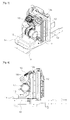
- FIGS. 5 and 6 are a perspective view and a side view of th e front side of an engine compartment of an agricultural work vehicle according to a second preferred embodiment of the pres ent invention.
- the drawings illustrate an engine compartment structure app licable to middle-sized models.
- the same components as the fi rst preferred embodiments have the same reference numerals as the first preferred embodiments.
- the a ir cleaner 17 is arranged adjacent to the plate 14 between the battery 15, which is mounted in a battery receiving space (its reference numeral is omitted) formed in the vehicle chassis f rame 10, and the air cleaner support 13a.
- the air cleaner 17 is transversely arranged in the width direction of the vehicl e body, and the engine control unit 18 is arranged above the ai r cleaner 17.
- the engine control unit 18 can be stably mounted above the air cleaner 17 by means of the fixing bracket 16 having the fi xed end at the air cleaner support 13a.
- the engine control unit 18 is mounted at the ce ntral portion of the upper part of the front of the air cleaner support 13a by fixing an end portion of the fixing bracket 16 at an approximately central portion of a horizontal member (it s reference numeral is omitted) mounted at the top of the air c leaner support.
- the engine control unit 18 When the engine control unit 18 is secured above the air c leaner 17 inside the engine compartment space in the above-men tioned structure, the engine control unit 18 is arranged in su ch a way that the rear face of the plane of the engine control unit 18 is inclined downwardly against the plane of the mesh 1 3 mounted on the air cleaner support, or as shown in FIGS. 7 an d 8, arranged in such a way that the rear face of the plane of the engine control unit 18 is faced with the plane of the mesh 13 in parallel.
- FIGS. 9 and 10 illustrate another modification of the sec ond preferred embodiment in which the engine control unit is a rranged adjacent to the side of the air cleaner.
- the engine control unit 18 is arranged in the engine compartment space spaced apart from the side of the air cleaner 17 at a predetermined interval and is adjacent to the air cleaner 17.
- the f ixing bracket 16 for securing the engine control unit 18 may b e fixed and secured on the vertical member (its reference nume ral is omitted) of the air cleaner support 13a.
- the engine control unit 18 is arranged i n such a way that the rear face of the plane of the engine cont rol unit 18 is inclined upwardly toward the center of the fron t end of the vehicle chassis frame.
- the eng ine control unit 18 is arranged at the left side of the air cle aner 17, but on the contrary, it is obvious to those skilled in the art that the engine control unit 18 may be arranged at the right side of the air cleaner 17.
- the agricultural work vehicle accordi ng to the preferred embodiments of the present invention include des the engine control unit arranged inside the engine compart ment utilizing a spare space for mounting the battery inside t he engine compartment, such that the engine control unit (ECU) can be mounted in the limited engine compartment space withou t changing the lay-out of the engine compartment of the conven tional agricultural work vehicle.
- ECU engine control unit
- the agricultural work vehicle can reduce expenses for additionally mounting the engine contr ol unit, secure easiness in mounting the engine control unit, and utilize the limited engine compartment space more effectiv ely.
- the agricultur al work vehicle can effecti vely prevent overheat of the engine control unit from the outs ide cold air introduced from the front of the engine compartme nt hood, and allows the engine control unit to be mounted at th e optimum position that is never affected by radiant heat of t he radiator.
Landscapes
- Engineering & Computer Science (AREA)
- Mechanical Engineering (AREA)
- Chemical & Material Sciences (AREA)
- Combustion & Propulsion (AREA)
- Transportation (AREA)
- Life Sciences & Earth Sciences (AREA)
- Soil Sciences (AREA)
- Environmental Sciences (AREA)
- Cooling, Air Intake And Gas Exhaust, And Fuel Tank Arrangements In Propulsion Units (AREA)
- Body Structure For Vehicles (AREA)
Abstract
Description
- The present invention relates to an agricultural work vehicle, and more particularly, to an agricultural work vehicle having a structure that changes the layout of an engine compartment of the agricultural work vehicle less and effectively secure an engine control unit (ECU).
- An agricultural work vehicle is the same as general vehicles in structure, but is mainly used for cultivation because it is equipped with a strong power engine and has a good traction power and is strong. In order to use the agricultural work vehicle for cultivation, it may be selectively equipped with a farm working machinery (for instance, a rotary device), which have a structure suitable for covering up seed with soil or leveling ground work as occasion demands.
- A rotary power for actuating the farm working machinery mounted on the agricultural work vehicle is generated from a main engine of the agricultural work vehicle. The conventional agricultural work vehicle generally and widely adopts a method that the movement of the engine is mechanically controlled by a cable displacement and an adjustment of the degree of opening of a throttle valve due to a manipulation of a foot acceleration pedal or a hand acceleration pedal (or a hand acceleration lever).
- However, such a conventional agricultural work vehicle adopting the mechanically engine-controlling method has a problem in that it is deteriorated in the general vehicle performances (fuel efficiency, effect, exhaust gas control, and so on) because it is difficult to precisely control the engine core functions, such as ignition time, fuel injection time, idle rotation, and so on. In order to overcome the above-mentioned problem, recently, an attempt to apply an engine control unit (ECU), which has been applied to general vehicles, also to the agricultural work vehicle has been spread.
- In order to apply the engine control unit to the conventional agricultural work vehicle, an additional space for arranging the engine control unit inside a limited engine compartment space must be secured. For this, because the entire lay out of the engine compartment must be changed or the engine compartment space must be enlarged, the entire appearance of the work vehicle is changed or the size of the engine compartment space is increased.
- Accordingly, the present invention has been made in an effort to solve the above-mentioned problems occurring in the prior arts, and it is an object of the present invention to provide an agricultural work vehicle having a structure that changes the layout of an engine compartment of the agricultural work vehicle less and effectively secure an engine control unit (ECU).
- To achieve the above objects, the present invention provides an agricultural work vehicle including: a radiator mounted on the vehicle chassis frame in front of the engine in the engine compartment; an air cleaner support disposed in front of the radiator; the vehicle chassis, the length of which extends forward in front of the air cleaner support; a battery stored in the space created by the vehicle chassis frame extending forward in front of the air cleaner support; and an engine control unit securely disposed above the battery inside an engine compartment space by means of a fixing bracket secured to a side of the air cleaner support.
- In an aspect of the present invention, the agricultural work vehicle further includes: a mesh mounted on the air cleaner support; and an air cleaner arranged in the engine compartment space spaced upwardly from the battery by means of the air cleaner support, the air cleaner being supported on the air cleaner support in such a manner that the air cleaner is inclined downwardly at a predetermined angle toward the front of the vehicle body.
- In this instance, the fixing bracket is securely mounted at a vertical member of a side of the air cleaner support, and the rear face of the plane of the engine control unit is arranged to form an angle with the plane of the mesh by the fixing bracket.
- Differently from the above, the fixing bracket is securely mounted at a vertical member of a side of the air cleaner support, and the rear face of the plane of the engine control unit is faced with the plane of the mesh by the fixing bracket in parallel.
- In another aspect of the present invention, the agricultural work vehicle further includes: a mesh mounted on the air cleaner support; and an air cleaner arranged in a space between the battery and the air cleaner support by means of the air cleaner support.
- In this instance, the fixing bracket is securely fixed at a horizontal member of the air cleaner support above the air cleaner, and the engine control unit is mounted above the air cleaner in front of the air cleaner support by means of the fixing bracket.
- The engine control unit is mounted in such a way that the rear face of the plane of the engine control unit is inclined d ownwardly against the plane of the mesh, or the rear face of th e plane of the engine control unit is faced with the plane of t he mesh in parallel.
- Differently from the above, the fixing bracket is securel y mounted at a vertical member of the air cleaner support of a side of the air cleaner, and the engine control unit is mounte d at the side of the air cleaner by means of the fixing bracket . In this instance, the engine control unit is mounted in such a way that the rear face of the plane of the engine control un it is inclined toward the center of the front end of the vehicl e chassis frame.
- In the present invention, the agricultural work vehicle f urther includes a plate mounted on the vehicle chassis frame e xtending in front of the air cleaner support, the battery bein g mounted in a receiving space formed in the vehicle chassis f rame by perforating the center of the plate.
- The agricultural work vehicle according to the present invention includes the engine control unit arranged inside the engine compartment utilizing a spare space for mounting the battery inside the engine compartment, such that the engine control unit (ECU) can be mounted in the limited engine compartment space without changing the lay-out of the engine compartment of the conventional agricultural work vehicle.
- Moreover, because the engine control unit is mounted in the engine compartment in front of the radiator, the agricultural work vehicle according to the present invention can effectively prevent overheat of the engine control unit from the outside cold air introduced from the front of the engine compartment hood, and allows the engine control unit to be mounted at the optimum position that is never affected by radiant heat of the radiator.
-
-
FIG. 1 is a perspective view of the front side of an engin e compartment of an agricultural work vehicle according to a f irst preferred embodiment of the present invention. -
FIG. 2 is a side view of the engine compartment ofFIG. 1 . -
FIG. 3 is a view showing a modification of the agricultura l work vehicle according to the first preferred embodiment. -
FIG. 4 is a side view of an engine compartment according t
o the modification ofFIG. 3 . -
FIG. 5 is a perspective view of the front side of an engin e compartment of an agricultural work vehicle according to a s econd preferred embodiment of the present invention. -
FIG. 6 is a side view of the engine compartment ofFIG. 5 . -
FIG. 7 is a view showing a modification of the agricultura l work vehicle according to the second preferred embodiment. -
FIG. 8 is a side view of an engine compartment according t o the modification ofFIG. 7 . -
FIG. 9 is a view showing another modification of the agric ultural work vehicle according to the second preferred embodim ent. -
FIG. 10 is a side view of the engine compartment ofFIG. 9 - Reference will be now made in detail to the preferred embo diments of the present invention with reference to the attache d drawings. In the present invention, description of the same configuration and action as the prior arts will be omitted, a nd when it is judged that detailed descriptions of known funct ions or structures related with the present invention may make the essential points vague, the detailed descriptions of the known functions or structures will be omitted. In description of the preferred embodiments of the present invention, the sa me components have the same reference numerals in the drawings
-
FIG. 1 is a perspective view of the front side of an engin e compartment of an agricultural work vehicle according to a f irst preferred embodiment of the present invention, andFIG. 2 is a side view of the engine compartment ofFIG. 1 , namely, FI GS. 1 and 2 illustrate an arrangement structure of the engine compartment which may be applied to large-sized models. - Referring to
FIGS. 1 and 2 , anengine compartment 1 in the agricultural work vehicle, for instance, a tractor, is genera lly formed in the front of a vehicle body. Theengine compartm ent 1 is divided into avehicle chassis frame 10 and an engine compartment hood (its reference numeral is omitted). Such anengine compartment 1 is equipped with an engine (not shown) an d main compartments related with operation of the vehicle body , for instance, an oil fan (not shown), abattery 15, aradiato r 12, and others. - The
radiator 12 is arranged on thevehicle chassis frame 1 0 in front of the engine inside theengine compartment 1. More over, thevehicle chassis frame 10 extends more in front of the radiator 12. Therefore, as shown in the drawings, the vehicle chassis frame 10 in front of theradiator 12 secures a space for mounting main components, such as an air cleaner support 13a and abattery 15, on thevehicle chassis frame 10. - A
plate 14 may be mounted on thevehicle chassis frame 10 extending in front of theradiator 12. Theplate 14 functions to block introduction of foreign matters, such as dust, from t he lower part of the vehicle body toward theengine compartmen t 1 while the vehicle runs. Additionally, theplate 14 provid es a mounting surface for allowing the main components, for in stance, theradiator 12 and the air cleaner support 13a, to be mounted in stability. - The
battery 15 is transversely arranged on the vehicle ch assisframe 10 extending in front of the air cleaner support i n the width direction of the vehicle body. In detail, thebatt ery 15 can be firmly mounted inside a receiving space (there i s no reference numeral), which is formed in the vehicle chassi sframe 10 by perforating the center of theplate 14 on the vehicle chassis frame 10, by a holder or a bracket (not shown) wit hout generating any movement during running of the vehicle bod y. - An engine control unit (ECU) 18 for precisely controlling the core functions of the engine, for instance, ignition time , fuel injection time, and idle rotation, is arranged above th
e battery 15 inside an engine compartment space. In detail, t heengine control unit 18 is spaced apart from theplate 14, wh ich forms an engine compartment floor by means of afixing bra cket 16 which forms a fixed end on theair cleaner support 13a. - As shown in
FIGS. 1 and 2 illustrating the first preferred embodiment of the present invention, theengine control unit 18 may be mounted in such a manner that the rear face of the pl ane of theengine control unit 18 is arranged to form an angle with the plane of amesh 13 mounted on theair cleaner support 13a by means of thefixing bracket 16 mounted at a vertical mem ber of a side (left side) of theair cleaner support 13a, for i nstance, arranged in such a manner that the plane of themesh 1 3 is at right angles to the rear face of the plane of the engine control unit 18. - The
fixing bracket 16 may be changed in shape and structur e according to the shape or the structure of the engine control unit 18. Therefore, thefixing bracket 16 is not limited to the shape and the structure illustrated in the drawings. In o ther words, if theengine control unit 18 located in the space in front of theair cleaner support 13a can be stably supporte d without any interference from other components, any fixing b racket can be applied without any special limitation. - The
reference numeral 17 designates an air cleaner for fi ltering foreign matters when the outside air is introduced int o the engine for fuel-air mixture. - In the first preferred embodiment, as shown in the drawin gs, the
air cleaner 17 is stably secured in the inside space of theengine compartment 1 upwardly separated from thebattery 15 by theair cleaner support 13a. In this instance, theair c leaner 17 is inclined downwardly at a predetermined angle towa rd the front of the vehicle body in order to effectively utili ze wind generated when the vehicle runs and in consideration o f the entire lay-out limited by an engine compartment hood. - The
mesh 13 is mounted on theair cleaner support 13a in o rder to prevent foreign matters introduced from the outside du ring running of the vehicle from being directly introduced int o theradiator 12. Furthermore, a condenser (its reference nu meral is omitted) for condensing refrigerant may be mounted be tween themesh 13 and theradiator 12 just in case of a cabin a gricultural work vehicle with advanced features having an air conditioner. -
FIG. 3 is a view showing a modification of the agricultura l work vehicle according to the first preferred embodiment, an dFIG. 4 is a side view of an engine compartment according to t he modification ofFIG. 3 . - In the modification illustrated in
FIGS. 3 and 4 , like the first preferred embodiment, theengine control unit 18 is mou nted above the battery inside the engine compartment space by means of the fixingbracket 16 fixed at one side of the aircle aner support 13a. In this instance, except in the case that th ere is a little difference in detailed arrangement of the engine control unit 18, there is little difference in structure be tween the first preferred embodiment and the modification. - Referring to
FIGS. 3 and 4 , theengine control unit 18 is located above the battery inside the engine compartment space by means of the fixingbracket 16 fixed at one side of theair cleaner support 13a. Like the first preferred embodiment, thebattery 15 is transversely arranged on the vehicle chassis frame 10 extending in front of the air cleaner support in the wid th direction of the vehicle body, and theradiator 12 is arran ged on theplate 14 in the rear of thebattery 15. In addition , theair cleaner support 13a is mounted between theradiator 12 and thebattery 15. - The
engine control unit 18 is located in the space in fron t of themesh 13 mounted on theair cleaner support 13a by mean s of the fixingbracket 16 having the fixed end on the vertical member at one side of theair cleaner support 13a. In detail, theengine control unit 18 in this embodiment is mounted in su ch a way that the rear face of the plane of theengine control unit 18 is faced with the plane of themesh 13 in parallel. -
FIGS. 5 and 6 are a perspective view and a side view of th e front side of an engine compartment of an agricultural work vehicle according to a second preferred embodiment of the pres ent invention. Differently from the first preferred embodimen t, the drawings illustrate an engine compartment structure app licable to middle-sized models. The same components as the fi rst preferred embodiments have the same reference numerals as the first preferred embodiments. - Differently from the first preferred embodiment, in the s econd preferred embodiment illustrated in
FIGS. 5 and 6 , the air cleaner 17 is arranged adjacent to theplate 14 between thebattery 15, which is mounted in a battery receiving space (its reference numeral is omitted) formed in the vehiclechassis f rame 10, and theair cleaner support 13a. In this instance, as shown in the drawings, like thebattery 15, theair cleaner 17 is transversely arranged in the width direction of the vehicl e body, and theengine control unit 18 is arranged above theai r cleaner 17. - The
engine control unit 18 can be stably mounted above theair cleaner 17 by means of the fixingbracket 16 having the fi xed end at theair cleaner support 13a. Preferably, as shown i n the drawings, theengine control unit 18 is mounted at the ce ntral portion of the upper part of the front of theair cleaner support 13a by fixing an end portion of the fixingbracket 16 at an approximately central portion of a horizontal member (it s reference numeral is omitted) mounted at the top of the air c leaner support. - When the
engine control unit 18 is secured above the air c leaner 17 inside the engine compartment space in the above-men tioned structure, theengine control unit 18 is arranged in su ch a way that the rear face of the plane of theengine control unit 18 is inclined downwardly against the plane of themesh 1 3 mounted on the air cleaner support, or as shown inFIGS. 7 an d 8, arranged in such a way that the rear face of the plane of theengine control unit 18 is faced with the plane of themesh 13 in parallel. -
FIGS. 9 and 10 illustrate another modification of the sec ond preferred embodiment in which the engine control unit is a rranged adjacent to the side of the air cleaner. - In the second modification of the second preferred embodi ment illustrated in
FIGS. 9 and 10 , theengine control unit 18 is arranged in the engine compartment space spaced apart from the side of theair cleaner 17 at a predetermined interval and is adjacent to theair cleaner 17. For this arrangement, thef ixing bracket 16 for securing theengine control unit 18 may b e fixed and secured on the vertical member (its reference nume ral is omitted) of theair cleaner support 13a. - In order to arrange the
engine control unit 18 to the side ofair cleaner 17, in consideration of the entire lay-out lim ited by the engine compartment hood, as shown in the drawings, it is preferable that theengine control unit 18 is arranged i n such a way that the rear face of the plane of the enginecont rol unit 18 is inclined upwardly toward the center of the fron t end of the vehicle chassis frame. - In the drawings, when it is viewed from the front, the eng ine
control unit 18 is arranged at the left side of theair cle aner 17, but on the contrary, it is obvious to those skilled in the art that theengine control unit 18 may be arranged at the right side of theair cleaner 17. - As described above, the agricultural work vehicle accordi ng to the preferred embodiments of the present invention inclu des the engine control unit arranged inside the engine compart ment utilizing a spare space for mounting the battery inside t he engine compartment, such that the engine control unit (ECU) can be mounted in the limited engine compartment space withou t changing the lay-out of the engine compartment of the conven tional agricultural work vehicle.
- In other words, because the engine control unit can be add itionally arranged in the limited engine compartment space wit hout changing the arrangement form of the main components, the agricultural work vehicle according to the present invention can reduce expenses for additionally mounting the engine contr ol unit, secure easiness in mounting the engine control unit, and utilize the limited engine compartment space more effectiv ely.
- Moreover, because the engine control unit is mounted in t he engine compartment in front of the radiator, the agricultur al work vehicle according to the present invention can effecti vely prevent overheat of the engine control unit from the outs ide cold air introduced from the front of the engine compartme nt hood, and allows the engine control unit to be mounted at th e optimum position that is never affected by radiant heat of t he radiator.
- While the particular embodiments of the present invention have been particularly described in this specification of the present invention and shown with reference to the attached drawings, it should be understood that there is no intent to limit the example embodiments of the present invention to the particular forms disclosed, but on the contrary, example embodiments of the invention are to cover all modifications, equivalents, and alternatives falling within the spirit and scope of the invention defined by the claims.
-
- 1:
- engine compartment
- 10:
- vehicle chassis frame
- 12:
- radiator
- 13:
- mesh
- 13a:
- air cleaner support
- 14:
- plate
- 15:
- battery
- 16:
- fixing bracket
- 17:
- air cleaner
- 18:
- engine control unit (ECU)
Claims (11)
- An agricultural work vehicle comprising:a radiator mounted on the vehicle chassis frame in front of the engine in the engine compartment;an air cleaner support disposed in front of the radiator;the vehicle chassis, the length of which extends forward in front of the air cleaner support;a battery stored in the space created by the vehicle chassis frame extending forward in front of the air cleaner support; andan engine control unit securely disposed above the battery inside an engine compartment space by means of a fixing bracket secured to a side of the air cleaner support.
- The agricultural work vehicle according to claim 1, further comprising:a mesh mounted on the air cleaner support; andan air cleaner arranged in the engine compartment space spaced upwardly from the battery by means of the air cleaner support, the air cleaner being supported on the air cleaner support in such a manner that the air cleaner is inclined downwardly at a predetermined angle toward the front of the vehicle body.
- The agricultural work vehicle according to claim 2, wherein the fixing bracket is securely mounted at a vertical member of a side of the air cleaner support, and the rear face of the plane of the engine control unit is arranged to form an angle with the plane of the mesh by the fixing bracket.
- The agricultural work vehicle according to claim 2, wherein the fixing bracket is securely mounted at a vertical member of a side of the air cleaner support, and the rear face of the plane of the engine control unit is faced with the plane of the mesh by the fixing bracket in parallel.
- The agricultural work vehicle according to claim 1, further comprising:a mesh mounted on the air cleaner support; andan air cleaner arranged in a space between the battery and the air cleaner support by means of the air cleaner support.
- The agricultural work vehicle according to claim 5, wherein the fixing bracket is securely fixed at a horizontal member of the air cleaner support above the air cleaner, and the engine control unit is mounted above the air cleaner in front of the air cleaner support by means of the fixing bracket.
- The agricultural work vehicle according to claim 6, where in the engine control unit is mounted in such a way that the re ar face of the plane of the engine control unit is inclined dow nwardly against the plane of the mesh.
- The agricultural work vehicle according to claim 6, where in the engine control unit is mounted in such a way that the re ar face of the plane of the engine control unit is faced with t he plane of the mesh in parallel.
- The agricultural work vehicle according to claim 5, where in the fixing bracket is securely mounted at a vertical member of the air cleaner support of a side of the air cleaner, and t he engine control unit is mounted at the side of the air cleane r by means of the fixing bracket.
- The agricultural work vehicle according to claim 9, where in the engine control unit is mounted in such a way that the re ar face of the plane of the engine control unit is inclined tow ard the center of the front end of the vehicle chassis frame.
- The agricultural work vehicle according to claim 1, furth er comprising:a plate mounted on the vehicle chassis frame extending in front of the air cleaner support, the battery being mounted in a receiving space formed in the vehicle chassis frame by perf orating the center of the plate.
Applications Claiming Priority (3)
| Application Number | Priority Date | Filing Date | Title |
|---|---|---|---|
| KR1020110015466A KR20120096203A (en) | 2011-02-22 | 2011-02-22 | Engine control unit equipping structure of agricultural vehicle |
| KR1020110015469A KR20120096206A (en) | 2011-02-22 | 2011-02-22 | A agricultural work vehicle |
| PCT/KR2012/001294 WO2012115423A2 (en) | 2011-02-22 | 2012-02-21 | Agricultural work vehicle |
Publications (2)
| Publication Number | Publication Date |
|---|---|
| EP2679448A2 true EP2679448A2 (en) | 2014-01-01 |
| EP2679448A4 EP2679448A4 (en) | 2015-08-26 |
Family
ID=46721323
Family Applications (1)
| Application Number | Title | Priority Date | Filing Date |
|---|---|---|---|
| EP12750255.7A Withdrawn EP2679448A4 (en) | 2011-02-22 | 2012-02-21 | Agricultural work vehicle |
Country Status (4)
| Country | Link |
|---|---|
| US (1) | US9004210B2 (en) |
| EP (1) | EP2679448A4 (en) |
| KR (1) | KR20140082592A (en) |
| WO (1) | WO2012115423A2 (en) |
Cited By (5)
| Publication number | Priority date | Publication date | Assignee | Title |
|---|---|---|---|---|
| JP2017030519A (en) * | 2015-07-31 | 2017-02-09 | ヤンマー株式会社 | Tractor |
| WO2017022216A1 (en) * | 2015-07-31 | 2017-02-09 | ヤンマー株式会社 | Tractor |
| JP2019209953A (en) * | 2018-06-08 | 2019-12-12 | 井関農機株式会社 | Work vehicle |
| CN111907447A (en) * | 2020-08-06 | 2020-11-10 | 建德希傅电子科技有限公司 | Storage battery installation device with sundry removing function |
| WO2022024628A1 (en) * | 2020-07-28 | 2022-02-03 | 株式会社クボタ | Work vehicle |
Families Citing this family (17)
| Publication number | Priority date | Publication date | Assignee | Title |
|---|---|---|---|---|
| US9303715B2 (en) | 2013-03-10 | 2016-04-05 | Oshkosh Defense, Llc | Limiting system for a vehicle suspension component |
| US10414266B1 (en) * | 2017-04-28 | 2019-09-17 | Oshkosh Defense, Llc | Vehicle cooling systems and methods |
| US12491943B1 (en) | 2013-03-10 | 2025-12-09 | Oshkosh Defense, Llc | Systems and methods for a military vehicle |
| US20140261286A1 (en) * | 2013-03-18 | 2014-09-18 | Caterpillar Inc. | Modular structure supporting engine enclosure |
| JP6401568B2 (en) * | 2014-10-16 | 2018-10-10 | ヤンマー株式会社 | Tractor |
| KR101968359B1 (en) * | 2014-12-22 | 2019-04-11 | 엘에스엠트론 주식회사 | ECU Mounting Bracket Assembly for Agricultural Operation Vehicle |
| KR102275197B1 (en) * | 2015-01-19 | 2021-07-08 | 주식회사 대동 | Agricultural vehicle and intake/cooling module assembling methods of the Agricultural vehicle |
| JP6540136B2 (en) * | 2015-03-23 | 2019-07-10 | 井関農機株式会社 | Work vehicle |
| JP6523824B2 (en) * | 2015-06-29 | 2019-06-05 | 三菱マヒンドラ農機株式会社 | Work vehicle |
| JP6733117B2 (en) * | 2016-10-24 | 2020-07-29 | 三菱マヒンドラ農機株式会社 | Work vehicle |
| KR102613090B1 (en) * | 2018-01-31 | 2023-12-12 | 주식회사 대동 | Prime moving part of Tractor |
| KR102488441B1 (en) * | 2018-02-09 | 2023-01-13 | 주식회사 대동 | Agricultural work vehicle |
| JP7032297B2 (en) * | 2018-12-27 | 2022-03-08 | 株式会社クボタ | Work platform |
| JP7581785B2 (en) * | 2020-11-17 | 2024-11-13 | 井関農機株式会社 | Riding lawn mower |
| JP2022159060A (en) * | 2021-03-31 | 2022-10-17 | 三菱マヒンドラ農機株式会社 | Working vehicle |
| JP7772660B2 (en) * | 2022-06-17 | 2025-11-18 | ヤンマーホールディングス株式会社 | combine |
| JP2025119484A (en) * | 2024-02-01 | 2025-08-14 | 株式会社クボタ | Tractor |
Family Cites Families (5)
| Publication number | Priority date | Publication date | Assignee | Title |
|---|---|---|---|---|
| JPH0761293A (en) | 1993-08-25 | 1995-03-07 | Honda Motor Co Ltd | Mounting structure of electronic control unit for engine |
| US20060220405A1 (en) * | 2005-03-31 | 2006-10-05 | Mazda Motor Corporation | Structure for arrangement of engine-associated vehicle components |
| JP4689357B2 (en) * | 2005-06-08 | 2011-05-25 | 株式会社小松製作所 | Work vehicle |
| US7383905B2 (en) * | 2006-08-07 | 2008-06-10 | Deere & Company | Vehicle cooling system |
| JP2010215165A (en) * | 2009-03-18 | 2010-09-30 | Honda Motor Co Ltd | Ecu layout structure of vehicle |
-
2012
- 2012-02-21 WO PCT/KR2012/001294 patent/WO2012115423A2/en not_active Ceased
- 2012-02-21 US US14/001,135 patent/US9004210B2/en not_active Expired - Fee Related
- 2012-02-21 EP EP12750255.7A patent/EP2679448A4/en not_active Withdrawn
- 2012-02-21 KR KR1020137027889A patent/KR20140082592A/en not_active Withdrawn
Cited By (10)
| Publication number | Priority date | Publication date | Assignee | Title |
|---|---|---|---|---|
| JP2017030519A (en) * | 2015-07-31 | 2017-02-09 | ヤンマー株式会社 | Tractor |
| WO2017022216A1 (en) * | 2015-07-31 | 2017-02-09 | ヤンマー株式会社 | Tractor |
| EP3330514A4 (en) * | 2015-07-31 | 2019-03-20 | Yanmar Co., Ltd. | Tractor |
| US10507773B2 (en) | 2015-07-31 | 2019-12-17 | Yanmar Co., Ltd. | Tractor |
| US11198404B2 (en) | 2015-07-31 | 2021-12-14 | Yanmar Power Technology Co., Ltd. | Tractor |
| JP2019209953A (en) * | 2018-06-08 | 2019-12-12 | 井関農機株式会社 | Work vehicle |
| WO2022024628A1 (en) * | 2020-07-28 | 2022-02-03 | 株式会社クボタ | Work vehicle |
| JP2022024382A (en) * | 2020-07-28 | 2022-02-09 | 株式会社クボタ | Work vehicle |
| US12098693B2 (en) | 2020-07-28 | 2024-09-24 | Kubota Corporation | Work vehicle |
| CN111907447A (en) * | 2020-08-06 | 2020-11-10 | 建德希傅电子科技有限公司 | Storage battery installation device with sundry removing function |
Also Published As
| Publication number | Publication date |
|---|---|
| KR20140082592A (en) | 2014-07-02 |
| WO2012115423A2 (en) | 2012-08-30 |
| US20130327582A1 (en) | 2013-12-12 |
| US9004210B2 (en) | 2015-04-14 |
| WO2012115423A3 (en) | 2012-11-01 |
| EP2679448A4 (en) | 2015-08-26 |
Similar Documents
| Publication | Publication Date | Title |
|---|---|---|
| EP2679448A2 (en) | Agricultural work vehicle | |
| AU2010236034B2 (en) | Towing tractor | |
| US20230219630A1 (en) | Hood and tractor equipped with hood | |
| JP2597915B2 (en) | Combustion air suction device for automobile front engine | |
| JPS5847220Y2 (en) | motorcycle radiator device | |
| JP4689071B2 (en) | Bonnet structure of tractor | |
| JP2006160261A (en) | Lower body structure of automobile | |
| JP2021160605A (en) | Saddle-riding type vehicle | |
| KR20120096201A (en) | Engine control unit equipping structure of agricultural vehicle | |
| RU2010136333A (en) | OFF-VEHICLE VEHICLE HAVING A COOLING TUNNEL | |
| WO2018069899A1 (en) | A storage shell for a two wheeled vehicle | |
| JPH07228280A (en) | Step mounting structure for motorcycles | |
| JP2006160262A (en) | Lower body structure of automobile | |
| JP2668783B2 (en) | Motorcycle | |
| JP2566507Y2 (en) | Riding agricultural work machine | |
| JPS6245116B2 (en) | ||
| JP3683658B2 (en) | Agricultural machine | |
| CN217241466U (en) | Harvester | |
| JPH0446968Y2 (en) | ||
| JPS5936496Y2 (en) | Support structure of exhaust system in tractor | |
| JP2504663Y2 (en) | Muffler mounting structure for mobile agricultural machinery | |
| CN208232798U (en) | Medium-sized imitative Cowes spy vehicle rear-engine bus structure | |
| RU32074U1 (en) | Subcompact car | |
| JPH0338287U (en) | ||
| JPS6029631Y2 (en) | Engine cooling system in vehicles |
Legal Events
| Date | Code | Title | Description |
|---|---|---|---|
| PUAI | Public reference made under article 153(3) epc to a published international application that has entered the european phase |
Free format text: ORIGINAL CODE: 0009012 |
|
| 17P | Request for examination filed |
Effective date: 20130910 |
|
| AK | Designated contracting states |
Kind code of ref document: A2 Designated state(s): AL AT BE BG CH CY CZ DE DK EE ES FI FR GB GR HR HU IE IS IT LI LT LU LV MC MK MT NL NO PL PT RO RS SE SI SK SM TR |
|
| DAX | Request for extension of the european patent (deleted) | ||
| A4 | Supplementary search report drawn up and despatched |
Effective date: 20150727 |
|
| RIC1 | Information provided on ipc code assigned before grant |
Ipc: B60R 16/02 20060101AFI20150721BHEP Ipc: F02M 35/04 20060101ALI20150721BHEP Ipc: A01B 49/00 20060101ALI20150721BHEP |
|
| GRAP | Despatch of communication of intention to grant a patent |
Free format text: ORIGINAL CODE: EPIDOSNIGR1 |
|
| INTG | Intention to grant announced |
Effective date: 20160308 |
|
| STAA | Information on the status of an ep patent application or granted ep patent |
Free format text: STATUS: THE APPLICATION IS DEEMED TO BE WITHDRAWN |
|
| 18D | Application deemed to be withdrawn |
Effective date: 20160719 |