EP2679417A1 - Vehicle heating, ventilating and/or conditioning unit - Google Patents
Vehicle heating, ventilating and/or conditioning unit Download PDFInfo
- Publication number
- EP2679417A1 EP2679417A1 EP12004729.5A EP12004729A EP2679417A1 EP 2679417 A1 EP2679417 A1 EP 2679417A1 EP 12004729 A EP12004729 A EP 12004729A EP 2679417 A1 EP2679417 A1 EP 2679417A1
- Authority
- EP
- European Patent Office
- Prior art keywords
- air
- flap
- hot
- channel
- air outlet
- Prior art date
- Legal status (The legal status is an assumption and is not a legal conclusion. Google has not performed a legal analysis and makes no representation as to the accuracy of the status listed.)
- Granted
Links
Images


Classifications
-
- B—PERFORMING OPERATIONS; TRANSPORTING
- B60—VEHICLES IN GENERAL
- B60H—ARRANGEMENTS OF HEATING, COOLING, VENTILATING OR OTHER AIR-TREATING DEVICES SPECIALLY ADAPTED FOR PASSENGER OR GOODS SPACES OF VEHICLES
- B60H1/00—Heating, cooling or ventilating devices
- B60H1/00007—Combined heating, ventilating, or cooling devices
- B60H1/00021—Air flow details of HVAC devices
- B60H1/00064—Air flow details of HVAC devices for sending air streams of different temperatures into the passenger compartment
-
- B—PERFORMING OPERATIONS; TRANSPORTING
- B60—VEHICLES IN GENERAL
- B60H—ARRANGEMENTS OF HEATING, COOLING, VENTILATING OR OTHER AIR-TREATING DEVICES SPECIALLY ADAPTED FOR PASSENGER OR GOODS SPACES OF VEHICLES
- B60H1/00—Heating, cooling or ventilating devices
- B60H1/00507—Details, e.g. mounting arrangements, desaeration devices
- B60H1/00557—Details of ducts or cables
- B60H1/00564—Details of ducts or cables of air ducts
-
- B—PERFORMING OPERATIONS; TRANSPORTING
- B60—VEHICLES IN GENERAL
- B60H—ARRANGEMENTS OF HEATING, COOLING, VENTILATING OR OTHER AIR-TREATING DEVICES SPECIALLY ADAPTED FOR PASSENGER OR GOODS SPACES OF VEHICLES
- B60H1/00—Heating, cooling or ventilating devices
- B60H1/00642—Control systems or circuits; Control members or indication devices for heating, cooling or ventilating devices
- B60H1/00664—Construction or arrangement of damper doors
- B60H1/00671—Damper doors moved by rotation; Grilles
- B60H1/00678—Damper doors moved by rotation; Grilles the axis of rotation being in the door plane, e.g. butterfly doors
-
- B—PERFORMING OPERATIONS; TRANSPORTING
- B60—VEHICLES IN GENERAL
- B60H—ARRANGEMENTS OF HEATING, COOLING, VENTILATING OR OTHER AIR-TREATING DEVICES SPECIALLY ADAPTED FOR PASSENGER OR GOODS SPACES OF VEHICLES
- B60H1/00—Heating, cooling or ventilating devices
- B60H1/24—Ventilating devices where the heating or cooling is irrelevant
- B60H1/241—Ventilating devices where the heating or cooling is irrelevant characterised by the location of ventilation devices in the vehicle
- B60H1/242—Ventilating devices where the heating or cooling is irrelevant characterised by the location of ventilation devices in the vehicle located in the front area
-
- B—PERFORMING OPERATIONS; TRANSPORTING
- B60—VEHICLES IN GENERAL
- B60H—ARRANGEMENTS OF HEATING, COOLING, VENTILATING OR OTHER AIR-TREATING DEVICES SPECIALLY ADAPTED FOR PASSENGER OR GOODS SPACES OF VEHICLES
- B60H1/00—Heating, cooling or ventilating devices
- B60H1/00007—Combined heating, ventilating, or cooling devices
- B60H1/00021—Air flow details of HVAC devices
- B60H2001/00078—Assembling, manufacturing or layout details
- B60H2001/00092—Assembling, manufacturing or layout details of air deflecting or air directing means inside the device
Definitions
- the invention relates to a vehicle heating, ventilating and/or air conditioning unit comprising a housing for the unit in which air flow channels for hot and cold air flows are provided, and comprising a rotatable air flap for opening and closing at least one of air flow channels.
- Vehicle heating, ventilating and/or air conditioning units also known as HVAC units
- HVAC units have air mixing chambers in which hot and cold air is mixed and directed to a plurality of outlet openings leading to ventilation channels for different zones in the vehicle compartment, for example the wind shield, the foot area, the head area and front or rear zones of the vehicle compartment.
- Air flaps are provided in the output openings which allow the control of the air flow through each output opening.
- the air flaps can be controlled in a complex manner which requires complex automatic actuation of all air flaps, increasing the complexity and cost of the HVAC unit. It is also known to connect two or more air flaps with complex mechanical transmissions which require a plurality of moving parts.
- the object of the invention is to provide a multi-functional vehicle heating, ventilation and/or air condition unit having simple, compact and low cost design.
- a vehicle heating, ventilating and/or air conditioning unit comprising a housing for the unit in which air flow channels for hot and cold air flows are provided.
- the vehicle heating, ventilating and/or air conditioning unit further comprises a rotatable air flap for opening and closing at least one air flow channel, the air flap having a first flap wing with a first channel closure area and at least one second flap wing with a second channel closure area, which is preferably smaller than the first channel closure area.
- the second flap wing is, preferably, rigidly connected with the first flap wing wherein an intermediate air flow channel is formed between the first and second flap wings.
- This multifunctional air flap is able to control different air flow rates with the first and second flap wings, while allowing an air flow through the intermediate air flow channel.
- the at least two separate channel closure areas of the first and second flap wings allow the closure of respective air flow channels while the intermediate air flow channels formed between the first and second flap wings allow an air flow in the corresponding direction.
- the air flap has a simple design if the first and second flap wings are rigidly connected to each other and is therefore inexpensive to produce. It is neither required to have a complex automatic individual actuating mechanism for the different flap wings nor is a complex transmission mechanism with a plurality of moving components required
- the vehicle heating, ventilation and/or air conditioning unit may further comprise an air mixing chamber having hot and cold air inlet openings and at least two mixed air outlet openings wherein at least one of the mixed air outlet openings is associated with the air flap, the air flap having a closed position in which the mixed air outlet opening is closed by the first flap wing and an open position in which the mixed air outlet opening is open.
- Air mixing chambers with a plurality of mixed air outlet openings allow a compact design of the HVAC unit.
- the vehicle heating, ventilation and/or air conditioning unit further comprises at least one hot air tube channel within the air mixing chamber having a hot air outlet opening directed at the at least one mixed air outlet opening wherein the opening of the hot air tube channel is closed by the second flap wing in the closed position of the air flap.
- the hot air tube channel allows transport of hot air to an associated mixed air outlet opening. This allows a different local mixing ratio of hot and cold air at the associated mixed air outlet opening, thereby allowing individual temperature of the mixed air of different mixed air outlet openings of a single air mixing chamber.
- a HVAC unit with this design can be designed to be more compact with regard to HVAC units having multiple air mixing chambers.
- a vehicle heating, ventilating and/or air conditioning unit comprising an air mixing chamber having hot and cold air inlet openings and at least two mixed air outlet openings with air flaps which are able to close the corresponding mixed air outlet openings, wherein an air guiding element is provided in the mixing chamber.
- the air guiding element comprises at least one hot air tube channel extending from the hot air inlet opening and having an hot air outlet opening in front of one of the mixed air outlet openings.
- a closing mechanism is provided which closes the hot air outlet opening of the hot air tube channel when the air flap of the associated mixed air outlet opening is in a closed position, and which opens the opening of the hot air tube channel when the air flap of the associated mixed air outlet opening is in an open position.
- the closing mechanism is formed by the air flap of the associated mixed air outlet opening, the air flap having a first flap wing with a first channel closure area to close the mixed air outlet opening and at least one second flap wing with a second channel closure area which is smaller than the first channel closure area to close the hot air outlet opening of the hot air tube channel, the second flap wing being rigidly connected to the first flap wing wherein an intermediate air flow channel is formed between the first and second flap wings.
- the vehicle heating, ventilating and/or air conditioning units according to the invention may have a plurality of hot air channels which are arranged parallel to each other and are spaced apart from each other, forming a cold air channel within the air mixing chamber between them.
- the air flap comprises a plurality of second flap wings connected to the first flap wing. This allows the plurality of second flap wings and their corresponding second channel closure areas to close corresponding air flow channels.
- First and second air flap wings may comprise sections which are arranged in parallel plains.
- An air flow through the intermediate air flow channel formed between the first and second flap wings may be improved if a spacer is provided between the first and second flap wings, the spacer being arranged in parallel to the air flow in the intermediate air flow channel formed between the first and second flap wings.
- the second channel closure area may be between 75 % and 25 %, preferably between 55 % and 45 % of the channel closure area.
- FIG. 1 shows a schematic section view of a vehicle air heating, ventilation and/or air conditioning unit 10, in the following called HVAC unit 10.
- the HVAC unit 10 comprises a blower unit 12 which blows air through a system of air flow channels.
- the HVAC unit 10 may comprises a cooling device 14 provided in the main air flow channel and allows cooling and drying of the air supplied by the blower unit 12. Further, a filter element might be provided in the main air flow channel.
- the main air flow channel divides into a cold air flow channel 16 for cold air and an hot air flow channel 18 for hot air.
- a heating device 20 is provided in the hot air flow channel 18 which is able to heat the air flowing through the hot air flow channel 18.
- Each of the cold air flow channel 16 and the hot air flow channel 18 for cold and hot air respectively is provided with a respective air flap 22, 24 which is able to control the air volume flowing through the cold air flow channel 16 and the hot air flow channel 18.
- a mixing chamber 26 is provided in the HVAC unit 10 to receive the air coming from the cold air flow channel 16 and/or the hot air flow channel 18.
- the mixing chamber 26 is shown delimited by dotted lines.
- Hot air from the hot air flow channel 18 can enter the mixing chamber 26 through a hot air inlet opening 28.
- Cold air can enter the mixing chamber 26 coming from the cold air flow channel 16 through a cold air inlet opening 30.
- the mixing chamber 26 has three mixed air outlet openings 32, 32', 33 through which mixed hot and cold air from the air mixing chamber 26 can flow to different regions of the vehicle compartment for ventilation.
- the air flows to and from the air mixing chamber 26 are represented by corresponding arrows in Figure 1 .
- Each mixed air outlet opening 32, 32', 33 is provided with an air flap 34, 34', 35 which is able to control the volume of mixed air flowing through the corresponding mixed air outlet opening 32, 32', 33.
- Figure 2 shows a second section view of the HVAC unit 10 at a sectional plane parallel to that of Figure 1 .
- An air guiding element 36 is provided in the mixing chamber 26.
- the air guiding element 36 comprises at least one hot air tube channel 38.
- three hot air tube channels 38 are provided which are arranged parallel to each other and are spaced apart from each other, forming a cold air channel within the air mixing chamber 26 between them.
- the cold air channel is arranged in the sectional plane of Figure 1 and is indicated in Figure 2 by the dashed arrow coming from the cold air flow channel 16.
- the hot air tube channel 38 extends from the hot air inlet opening 28 and has a hot air outlet opening 40 in front of the mixed air outlet opening 33.
- all three hot air tube channels 38 are directed towards the same mixed air outlet opening 33. Hot air can, therefore, flow directly from the hot air flow channel 18 through the hot air tube channel 38 toward the mixed air outlet opening 33 in front of the hot air outlet opening 40 of the hot air tube channel 38.
- different hot air tube channels 38 can be directed towards different mixed air outlet openings 32, 33.
- the air guiding element 36 is further provided with hot air mixing openings 41 which allow hot air to flow directly from the hot air flow channel 18 through the hot air inlet opening 28 into the air mixing chamber 26.
- This air flow is indicated in Figure 2 by the second dashed arrow leading from the hot air flow channel 18 into the mixing chamber 26.
- the air guiding element 36 allows specific mixing ratios of hot and cold air for the different mixed air outlet openings of the HVAC unit 10. As the hot air tube channels 38 allow hot air to flow directly from the hot air inlet opening 28 to the corresponding mixed air outlet opening 33 a higher ratio of hot air to cold air can be realized for this specific mixed air outlet opening 33 as opposed to the remaining two mixed air outlet openings 32.
- a closing mechanism 42 is provided which is able to close the hot air outlet opening 40 of the hot air tube channel 38 when the air flap 35 of the associated mixed air outlet opening 33 is in a closed position and is able to open the hot air outlet opening 40 of the hot air tube channel 38 when the air flap 35 of the associated mixed air outlet opening 33 is in an open position.
- the closing mechanism 42 is formed by the air flap 35 of the associated mixed air outlet opening 33.
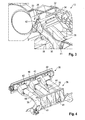
- Figure 3 shows a detailed section view of the mixing chamber 26 of the HVAC unit 10, the sectional plane corresponding to the one of Figure 2 .
- a number of elements such as the blower unit 12, the air cooling device 14 and the air flap 22 of the cold air flow channel 16 are not shown.
- the air flap 35 of the associated mixed air outlet opening 33 is shown in its closed position.
- the closing mechanism 42 is closing the hot air outlet opening 40 of the hot air tube channel 38.
- the closing mechanism 42 prevents hot air from exiting the hot air tube channels 38 through the hot air outlet opening 40 when the air flap 35 of the associated mixed air outlet opening 33 is in a closed position.
- the closing mechanism 42 prevents hot air from exiting the hot air tube channels 38 through the hot air outlet opening 40 by the hot air flowing against the air flap 35 in its closed position, and by the hot air being redirected back into the air mixing chamber 26. Thereby the local mixing ratio of hot and cold air in particular near the neighboring mixed air outlet opening 32 is changed.
- Figure 4 shows a three-dimensional view of the air guiding element 36 and the air flap 35 of the associated mixed air outlet opening 33 with the corresponding closing mechanism 42.
- the hot air tube channels 38 are arranged parallel to each other and are spaced apart from each other forming cold air channels 44 between each other.
- the hot air tube channels 38 are positioned downstream of the cold air inlet opening 30 and serve as baffle elements in the air flow coming from the cold air flow channel 16.
- the baffle elements create a turbulent air flow which enhances the mixing of hot and cold air in the mixing chamber 26.
- FIG. 5 shows the air flap 35 of the mixed air outlet opening 33 associated with the hot air tube channels 38 of the air guiding element 36.
- the closing mechanism is formed by the air flaps 35 of the mixed air outlet opening 33 associated with the hot air tube channels 38.
- the air flap 35 has a first flap wing 46 having a first channel closure area A (see Figure 6 ) which corresponds to the cross-section of the mixed air outlet opening 33.
- the first flap wing 46 is able to close the mixed air outlet opening 33.
- the air flap 35 further has at least one second flap wing 48.
- three second flap wings 48 are provided, with a second channel closure area B (see Figure 6 ).
- the second channel closure area B is smaller than the first channel closure area A of the first flap wing 46.
- the second flap wings 48 are each able to close a corresponding hot air outlet opening 40 of the hot air tube channels 38.
- the second closure area B is the total of the closure areas C (see Figure 5 , dotted lines) of each second flap wing 48, i.e. those portions of the second flap wings 48 which close their corresponding openings 40.
- the second flap wings 48 are rigidly connected to the first flap wing 46.
- the rigid connection is formed by spacers 50 which are provided to the first and second flap wings 46, 48.
- the spacer 50 is arranged in parallel to form an intermediate air flow channel 52 between the first and second flap wings 46, 48.
- Figure 6 shows the closing mechanism 42 with the air flap 35 in its closed position in which the first flap wing 46 closes the mixed air outlet opening 33 and the second flap wing 48 in turn closes the hot air outlet opening 40 of the hot air tube channel 38 of the air guiding element 36.
- first and second air flap wings 48, 46 comprise sections which are arranged in parallel planes.
- the intermediate air flow channel 52 lies between these parallel planes.
- Figure 7 shows the closing mechanism 42 with the air flap 35 in its open position in which the air flap 35 is rotated around its axis of rotation allowing an air flow to pass through the mixed air outlet opening 33.
- the rigidly connected second flap wing 48 is likewise rotated around the axis of rotation of the air flap 35, opening up the hot air outlet opening 40 of the hot air tube channel 38 of the air guiding element 36.
- Hot air flowing out of the hot air outlet opening 40 can flow through the intermediate air flow channel 52 formed between the first and second flap wings 46, 48.
- the closing mechanism 42 therefore does not disturb the air flow through the mixed air outlet opening 33.
- the total second closure area B of the three second air flap wings 48 corresponds to about 50 % of the first closure area A which corresponds to the cross-section of the mixed air outlet opening 33. It is also possible that the second closure area B is between 75 % and 25 %, preferably between 55 % and 45 % of the first closure area A.
- the mixed air outlet opening 33 associated with the hot air tube channels 38 of the air guiding element 36 is associated with the ventilation ducts leading to the wind shield which perform a defrosting function for the wind shield.
- the air guiding element 36 has hot air tube channels 38 extending towards different mixed air outlet openings 32, 33.
Landscapes
- Physics & Mathematics (AREA)
- Thermal Sciences (AREA)
- Engineering & Computer Science (AREA)
- Mechanical Engineering (AREA)
- Air-Conditioning For Vehicles (AREA)
Abstract
Description
- The invention relates to a vehicle heating, ventilating and/or air conditioning unit comprising a housing for the unit in which air flow channels for hot and cold air flows are provided, and comprising a rotatable air flap for opening and closing at least one of air flow channels.
- Vehicle heating, ventilating and/or air conditioning units, also known as HVAC units, have air mixing chambers in which hot and cold air is mixed and directed to a plurality of outlet openings leading to ventilation channels for different zones in the vehicle compartment, for example the wind shield, the foot area, the head area and front or rear zones of the vehicle compartment. Air flaps are provided in the output openings which allow the control of the air flow through each output opening.
- In order to achieve a consistent temperature control and mixing ratio of hot and cold air, the air flaps can be controlled in a complex manner which requires complex automatic actuation of all air flaps, increasing the complexity and cost of the HVAC unit. It is also known to connect two or more air flaps with complex mechanical transmissions which require a plurality of moving parts.
- Moreover, it is desirable to achieve air flow of different temperatures for different zones of the vehicle compartment. It is known on one hand to provide additional electric heating elements arranged in individual mixed air channel which allow independent additional heating of the corresponding air flow. On the other hand it is know to provide a plurality of independent mixing chambers wherein the mixing ratio of hot and cold air can be controlled independently. Both solutions require complex and bulky design of the HVAC unit.
- The object of the invention is to provide a multi-functional vehicle heating, ventilation and/or air condition unit having simple, compact and low cost design.
- This objective is solved by a vehicle heating, ventilating and/or air conditioning unit comprising a housing for the unit in which air flow channels for hot and cold air flows are provided. The vehicle heating, ventilating and/or air conditioning unit further comprises a rotatable air flap for opening and closing at least one air flow channel, the air flap having a first flap wing with a first channel closure area and at least one second flap wing with a second channel closure area, which is preferably smaller than the first channel closure area. The second flap wing is, preferably, rigidly connected with the first flap wing wherein an intermediate air flow channel is formed between the first and second flap wings.
- This multifunctional air flap is able to control different air flow rates with the first and second flap wings, while allowing an air flow through the intermediate air flow channel. The at least two separate channel closure areas of the first and second flap wings allow the closure of respective air flow channels while the intermediate air flow channels formed between the first and second flap wings allow an air flow in the corresponding direction. The air flap has a simple design if the first and second flap wings are rigidly connected to each other and is therefore inexpensive to produce. It is neither required to have a complex automatic individual actuating mechanism for the different flap wings nor is a complex transmission mechanism with a plurality of moving components required
- The vehicle heating, ventilation and/or air conditioning unit may further comprise an air mixing chamber having hot and cold air inlet openings and at least two mixed air outlet openings wherein at least one of the mixed air outlet openings is associated with the air flap, the air flap having a closed position in which the mixed air outlet opening is closed by the first flap wing and an open position in which the mixed air outlet opening is open. Air mixing chambers with a plurality of mixed air outlet openings allow a compact design of the HVAC unit.
- Preferably, the vehicle heating, ventilation and/or air conditioning unit further comprises at least one hot air tube channel within the air mixing chamber having a hot air outlet opening directed at the at least one mixed air outlet opening wherein the opening of the hot air tube channel is closed by the second flap wing in the closed position of the air flap.
- The hot air tube channel allows transport of hot air to an associated mixed air outlet opening. This allows a different local mixing ratio of hot and cold air at the associated mixed air outlet opening, thereby allowing individual temperature of the mixed air of different mixed air outlet openings of a single air mixing chamber. A HVAC unit with this design can be designed to be more compact with regard to HVAC units having multiple air mixing chambers.
- The objective of the invention is further solved by a vehicle heating, ventilating and/or air conditioning unit comprising an air mixing chamber having hot and cold air inlet openings and at least two mixed air outlet openings with air flaps which are able to close the corresponding mixed air outlet openings, wherein an air guiding element is provided in the mixing chamber. The air guiding element comprises at least one hot air tube channel extending from the hot air inlet opening and having an hot air outlet opening in front of one of the mixed air outlet openings.
- Preferably a closing mechanism is provided which closes the hot air outlet opening of the hot air tube channel when the air flap of the associated mixed air outlet opening is in a closed position, and which opens the opening of the hot air tube channel when the air flap of the associated mixed air outlet opening is in an open position.
- It is possible that the closing mechanism is formed by the air flap of the associated mixed air outlet opening, the air flap having a first flap wing with a first channel closure area to close the mixed air outlet opening and at least one second flap wing with a second channel closure area which is smaller than the first channel closure area to close the hot air outlet opening of the hot air tube channel, the second flap wing being rigidly connected to the first flap wing wherein an intermediate air flow channel is formed between the first and second flap wings.
- The vehicle heating, ventilating and/or air conditioning units according to the invention may have a plurality of hot air channels which are arranged parallel to each other and are spaced apart from each other, forming a cold air channel within the air mixing chamber between them.
- Preferably, the air flap comprises a plurality of second flap wings connected to the first flap wing. This allows the plurality of second flap wings and their corresponding second channel closure areas to close corresponding air flow channels.
- First and second air flap wings may comprise sections which are arranged in parallel plains.
- An air flow through the intermediate air flow channel formed between the first and second flap wings may be improved if a spacer is provided between the first and second flap wings, the spacer being arranged in parallel to the air flow in the intermediate air flow channel formed between the first and second flap wings.
- The second channel closure area may be between 75 % and 25 %, preferably between 55 % and 45 % of the channel closure area.
- Further features and advantages of the invention are disclosed in the following specification and the corresponding figures.
-
Figure 1 shows a first schematic section view of a vehicle heating, ventilation and/or air conditioning unit according to the invention with a mixing chamber; -
Figure 2 shows a second schematic section view of the vehicle heating, ventilation and/or air conditioning unit ofFigure 1 ; -
Figure 3 shows a three dimensional section view of the vehicle heating, ventilation and/or air conditioning unit according toFigure 2 ; -
Figure 4 shows detailed view of an air guiding element of the vehicle heating, ventilation and/or air conditioning unit ofFigure 3 ; -
Figure 5 shows a detailed view of an air flap of the vehicle heating, ventilation and/or air conditioning unit according to the invention; -
Figure 6 shows a detailed section view of the vehicle heating, ventilation and/or air conditioning unit ofFigure 3 with the air flap in its closed position; and -
Figure 7 shows the detailed section view ofFigure 6 with the air flap in its open position. -
Figure 1 shows a schematic section view of a vehicle air heating, ventilation and/orair conditioning unit 10, in the following calledHVAC unit 10. TheHVAC unit 10 comprises a blower unit 12 which blows air through a system of air flow channels. TheHVAC unit 10 may comprises acooling device 14 provided in the main air flow channel and allows cooling and drying of the air supplied by the blower unit 12. Further, a filter element might be provided in the main air flow channel. - In air flow direction downsteam of the
air cooling device 14, the main air flow channel divides into a coldair flow channel 16 for cold air and an hotair flow channel 18 for hot air. Aheating device 20 is provided in the hotair flow channel 18 which is able to heat the air flowing through the hotair flow channel 18. - Each of the cold
air flow channel 16 and the hotair flow channel 18 for cold and hot air respectively is provided with arespective air flap air flow channel 16 and the hotair flow channel 18. - A
mixing chamber 26 is provided in theHVAC unit 10 to receive the air coming from the coldair flow channel 16 and/or the hotair flow channel 18. InFigure 1 , themixing chamber 26 is shown delimited by dotted lines. - Hot air from the hot
air flow channel 18 can enter themixing chamber 26 through a hot air inlet opening 28. Cold air can enter themixing chamber 26 coming from the coldair flow channel 16 through a cold air inlet opening 30. - In the embodiment shown in
Figure 1 , themixing chamber 26 has three mixedair outlet openings air mixing chamber 26 can flow to different regions of the vehicle compartment for ventilation. The air flows to and from theair mixing chamber 26 are represented by corresponding arrows inFigure 1 . - Each mixed air outlet opening 32, 32', 33 is provided with an
air flap -
Figure 2 shows a second section view of theHVAC unit 10 at a sectional plane parallel to that ofFigure 1 . Anair guiding element 36 is provided in themixing chamber 26. Theair guiding element 36 comprises at least one hotair tube channel 38. In the present embodiment, three hotair tube channels 38 are provided which are arranged parallel to each other and are spaced apart from each other, forming a cold air channel within theair mixing chamber 26 between them. - The cold air channel is arranged in the sectional plane of
Figure 1 and is indicated inFigure 2 by the dashed arrow coming from the coldair flow channel 16. - The hot
air tube channel 38 extends from the hot air inlet opening 28 and has a hot air outlet opening 40 in front of the mixed air outlet opening 33. - In the present embodiment, all three hot
air tube channels 38 are directed towards the same mixed air outlet opening 33. Hot air can, therefore, flow directly from the hotair flow channel 18 through the hotair tube channel 38 toward the mixed air outlet opening 33 in front of the hot air outlet opening 40 of the hotair tube channel 38. Alternatively, different hotair tube channels 38 can be directed towards different mixedair outlet openings - The
air guiding element 36 is further provided with hotair mixing openings 41 which allow hot air to flow directly from the hotair flow channel 18 through the hot air inlet opening 28 into theair mixing chamber 26. This air flow is indicated inFigure 2 by the second dashed arrow leading from the hotair flow channel 18 into the mixingchamber 26. - The
air guiding element 36 allows specific mixing ratios of hot and cold air for the different mixed air outlet openings of theHVAC unit 10. As the hotair tube channels 38 allow hot air to flow directly from the hot air inlet opening 28 to the corresponding mixed air outlet opening 33 a higher ratio of hot air to cold air can be realized for this specific mixed air outlet opening 33 as opposed to the remaining two mixedair outlet openings 32. - A
closing mechanism 42 is provided which is able to close the hot air outlet opening 40 of the hotair tube channel 38 when theair flap 35 of the associated mixedair outlet opening 33 is in a closed position and is able to open the hot air outlet opening 40 of the hotair tube channel 38 when theair flap 35 of the associated mixedair outlet opening 33 is in an open position. - The
closing mechanism 42 is formed by theair flap 35 of the associated mixedair outlet opening 33. -
Figure 3 shows a detailed section view of the mixingchamber 26 of theHVAC unit 10, the sectional plane corresponding to the one ofFigure 2 . For reasons of clarity, a number of elements such as the blower unit 12, theair cooling device 14 and theair flap 22 of the coldair flow channel 16 are not shown. - The
air flap 35 of the associated mixedair outlet opening 33 is shown in its closed position. Theclosing mechanism 42 is closing the hot air outlet opening 40 of the hotair tube channel 38. Theclosing mechanism 42 prevents hot air from exiting the hotair tube channels 38 through the hotair outlet opening 40 when theair flap 35 of the associated mixedair outlet opening 33 is in a closed position. - The
closing mechanism 42 prevents hot air from exiting the hotair tube channels 38 through the hotair outlet opening 40 by the hot air flowing against theair flap 35 in its closed position, and by the hot air being redirected back into theair mixing chamber 26. Thereby the local mixing ratio of hot and cold air in particular near the neighboring mixedair outlet opening 32 is changed. -
Figure 4 shows a three-dimensional view of theair guiding element 36 and theair flap 35 of the associated mixed air outlet opening 33 with thecorresponding closing mechanism 42. The hotair tube channels 38 are arranged parallel to each other and are spaced apart from each other formingcold air channels 44 between each other. The hotair tube channels 38 are positioned downstream of the coldair inlet opening 30 and serve as baffle elements in the air flow coming from the coldair flow channel 16. The baffle elements create a turbulent air flow which enhances the mixing of hot and cold air in the mixingchamber 26. - The
closing mechanism 42 is further described in detail with regards toFigures 5, 6 and 7. Figure 5 shows theair flap 35 of the mixed air outlet opening 33 associated with the hotair tube channels 38 of theair guiding element 36. The closing mechanism is formed by the air flaps 35 of the mixed air outlet opening 33 associated with the hotair tube channels 38. - The
air flap 35 has afirst flap wing 46 having a first channel closure area A (seeFigure 6 ) which corresponds to the cross-section of the mixedair outlet opening 33. Thefirst flap wing 46 is able to close the mixedair outlet opening 33. - The
air flap 35 further has at least onesecond flap wing 48. In the present embodiment threesecond flap wings 48 are provided, with a second channel closure area B (seeFigure 6 ). Preferably, the second channel closure area B is smaller than the first channel closure area A of thefirst flap wing 46. Thesecond flap wings 48 are each able to close a corresponding hot air outlet opening 40 of the hotair tube channels 38. The second closure area B is the total of the closure areas C (seeFigure 5 , dotted lines) of eachsecond flap wing 48, i.e. those portions of thesecond flap wings 48 which close their correspondingopenings 40. - The
second flap wings 48 are rigidly connected to thefirst flap wing 46. - The rigid connection is formed by
spacers 50 which are provided to the first andsecond flap wings spacer 50 is arranged in parallel to form an intermediateair flow channel 52 between the first andsecond flap wings -
Figure 6 shows theclosing mechanism 42 with theair flap 35 in its closed position in which thefirst flap wing 46 closes the mixedair outlet opening 33 and thesecond flap wing 48 in turn closes the hot air outlet opening 40 of the hotair tube channel 38 of theair guiding element 36. - Advantageously, the first and second
air flap wings air flow channel 52 lies between these parallel planes. -
Figure 7 shows theclosing mechanism 42 with theair flap 35 in its open position in which theair flap 35 is rotated around its axis of rotation allowing an air flow to pass through the mixedair outlet opening 33. The rigidly connectedsecond flap wing 48 is likewise rotated around the axis of rotation of theair flap 35, opening up the hot air outlet opening 40 of the hotair tube channel 38 of theair guiding element 36. - Hot air flowing out of the hot
air outlet opening 40 can flow through the intermediateair flow channel 52 formed between the first andsecond flap wings closing mechanism 42 therefore does not disturb the air flow through the mixedair outlet opening 33. - As can be seen in
Figure 5 , the total second closure area B of the three secondair flap wings 48 corresponds to about 50 % of the first closure area A which corresponds to the cross-section of the mixedair outlet opening 33. It is also possible that the second closure area B is between 75 % and 25 %, preferably between 55 % and 45 % of the first closure area A. - In the present embodiment of the invention, the mixed air outlet opening 33 associated with the hot
air tube channels 38 of theair guiding element 36 is associated with the ventilation ducts leading to the wind shield which perform a defrosting function for the wind shield. - It is also possible that the
air guiding element 36 has hotair tube channels 38 extending towards different mixedair outlet openings
Claims (12)
- Vehicle heating, ventilating and/or air conditioning unit (10) comprising a housing for the unit in which air flow channels for hot and/or cold air flows are provided, and comprising at least one rotatable air flap (35) for opening and closing at least one of the air flow channels, the air flap (35) having a first flap wing (46) with a first channel closure area (A) and at least one second flap wing (48) with a second channel closure area (B), the second flap wing (48) being connected to the first flap wing (46),
wherein an intermediate air flow channel (52) is formed between the first and second flap wings (46, 48). - Vehicle heating, ventilating and/or air conditioning unit according to claim 1, further comprising an air mixing chamber (26) having hot and cold air inlet openings (28, 30) and at least two mixed air outlet openings (32, 33),
wherein at least one of the mixed air outlet openings (33) is associated with the air flap (35), the air flap (35) having a closed position in which the mixed air outlet opening (33) is closed by the first flap wing (46) and an open position in which the mixed air outlet opening (33) is open. - Vehicle heating, ventilating and/or air conditioning unit according to claim 2, further comprising at least one hot air tube channel (38) within the air mixing chamber (26) having a hot air outlet opening (40) in front of one of the mixed air outlet openings (33),
wherein the hot air outlet opening (40) of the hot air tube channel (38) is closed by the second flap wing (48) in the closed position of the air flap (35). - Vehicle heating, ventilating and/or air conditioning unit comprising an air mixing chamber (26) having hot and cold air inlet openings (28, 30) and at least two mixed air outlet openings (32, 33) with air flaps (34, 34', 35) which are able to close the corresponding mixed air outlet openings (32, 32', 33),
characterized in that an air guiding element (36) is provided in the mixing chamber (26), the air guiding element (36) comprising at least one hot air tube channel (38) extending from the hot air inlet opening (28) and having a hot air outlet opening (40) in front of one of the mixed air outlet openings (33). - Vehicle heating, ventilating and/or air conditioning unit according to claim 4, wherein a closing mechanism (42) is provided which is able to close the hot air outlet opening (40) of the hot air tube channel (38) when the air flap (35) of the associated mixed air outlet opening (33) is in a closed position and to open the hot air outlet opening (40) of the hot air tube channel (38) when the air flap (35) of the associated mixed air outlet opening (33) is in an open position.
- Vehicle heating, ventilating and/or air conditioning unit according to claim 5, wherein the closing mechanism (42) is formed by the air flap (35) of the associated mixed air outlet opening (33),
the air flap (34) having a first flap wing (46) with a first channel closure area (A) to close the mixed air outlet opening (33) and at least one second flap wing (48) with a second channel closure area (B) to close the hot air outlet opening (40) of the hot air tube channel (38),
the second flap wing (48) being rigidly connected to the first flap wing (46), wherein an intermediate air flow channel (52) is formed between the first and second flap wings (46, 48). - Vehicle heating, ventilating and/or air conditioning unit according to one of claims 3 to 6, wherein a plurality of hot air tube channels (38) are provided which are arranged parallel to each other and are spaced apart from each other, forming a cold air channel (44) within the air mixing chamber (26) between them.
- Vehicle heating, ventilating and/or air conditioning unit of one of claims 1 to 3 or 6 to 7, wherein the air flap (35) comprises a plurality of second flap wings (48) connected to the first flap wing (46).
- Vehicle heating, ventilating and/or air conditioning unit of one of claims 1 to 3 or 6 to 8, wherein the first and second air flap wings (46, 48) comprise sections which are arranged in parallel planes.
- Vehicle heating, ventilating and/or air conditioning unit of one of claims 1 to 3 or 6 to 9, wherein a spacer (50) is provided between the first and second flap wings (46, 48), the spacer (50) being arranged in parallel with the air flow in the intermediate air flow channel (52) formed between the first and second flap wings (46, 48).
- Vehicle heating, ventilating and/or air conditioning unit of one of claims 1 to 3 or 6 to 10, wherein the a second channel closure area (B) is smaller than the first channel closure area (A).
- Vehicle heating, ventilating and/or air conditioning unit of one of claims 1 to 3 or 6 to 11, wherein the second channel closure area is between 75% and 25%, preferably between 55% and 45%, of the first channel closure area.
Priority Applications (1)
| Application Number | Priority Date | Filing Date | Title |
|---|---|---|---|
| EP12004729.5A EP2679417B1 (en) | 2012-06-25 | 2012-06-25 | Vehicle Heating, Ventilating and/or Air conditioning unit |
Applications Claiming Priority (1)
| Application Number | Priority Date | Filing Date | Title |
|---|---|---|---|
| EP12004729.5A EP2679417B1 (en) | 2012-06-25 | 2012-06-25 | Vehicle Heating, Ventilating and/or Air conditioning unit |
Publications (2)
| Publication Number | Publication Date |
|---|---|
| EP2679417A1 true EP2679417A1 (en) | 2014-01-01 |
| EP2679417B1 EP2679417B1 (en) | 2015-03-04 |
Family
ID=46419866
Family Applications (1)
| Application Number | Title | Priority Date | Filing Date |
|---|---|---|---|
| EP12004729.5A Not-in-force EP2679417B1 (en) | 2012-06-25 | 2012-06-25 | Vehicle Heating, Ventilating and/or Air conditioning unit |
Country Status (1)
| Country | Link |
|---|---|
| EP (1) | EP2679417B1 (en) |
Cited By (1)
| Publication number | Priority date | Publication date | Assignee | Title |
|---|---|---|---|---|
| DE102021132061A1 (en) | 2021-12-06 | 2023-06-07 | Hanon Systems | Motor vehicle air conditioning |
Citations (5)
| Publication number | Priority date | Publication date | Assignee | Title |
|---|---|---|---|---|
| EP0865945A1 (en) * | 1997-03-18 | 1998-09-23 | Valeo Climatisation | Air distributing device for heating and/or air-conditioning the interior of a vehicle |
| FR2833530A1 (en) * | 2001-12-18 | 2003-06-20 | Valeo Climatisation | Automobile air conditioning equipment comprises frame containing air propulsion means, first and second optional air heating means, de-icing conduit and an ventilation conduits for compartment top and bottom zones |
| EP1445133A2 (en) * | 2003-02-10 | 2004-08-11 | Zexel Valeo Climate Control Corporation | Airconditioning system for automobiles |
| EP1564045A1 (en) * | 2004-02-17 | 2005-08-17 | Valeo Systèmes Thermiques | Air distribution unit for a heating, ventilation and/or air conditioning system of a vehicle |
| EP1616734A1 (en) * | 2004-07-16 | 2006-01-18 | Valeo Systèmes Thermiques | Control system of the ventilation temperature of a heating and air conditioning device for automotive vehicles |
-
2012
- 2012-06-25 EP EP12004729.5A patent/EP2679417B1/en not_active Not-in-force
Patent Citations (5)
| Publication number | Priority date | Publication date | Assignee | Title |
|---|---|---|---|---|
| EP0865945A1 (en) * | 1997-03-18 | 1998-09-23 | Valeo Climatisation | Air distributing device for heating and/or air-conditioning the interior of a vehicle |
| FR2833530A1 (en) * | 2001-12-18 | 2003-06-20 | Valeo Climatisation | Automobile air conditioning equipment comprises frame containing air propulsion means, first and second optional air heating means, de-icing conduit and an ventilation conduits for compartment top and bottom zones |
| EP1445133A2 (en) * | 2003-02-10 | 2004-08-11 | Zexel Valeo Climate Control Corporation | Airconditioning system for automobiles |
| EP1564045A1 (en) * | 2004-02-17 | 2005-08-17 | Valeo Systèmes Thermiques | Air distribution unit for a heating, ventilation and/or air conditioning system of a vehicle |
| EP1616734A1 (en) * | 2004-07-16 | 2006-01-18 | Valeo Systèmes Thermiques | Control system of the ventilation temperature of a heating and air conditioning device for automotive vehicles |
Cited By (1)
| Publication number | Priority date | Publication date | Assignee | Title |
|---|---|---|---|---|
| DE102021132061A1 (en) | 2021-12-06 | 2023-06-07 | Hanon Systems | Motor vehicle air conditioning |
Also Published As
| Publication number | Publication date |
|---|---|
| EP2679417B1 (en) | 2015-03-04 |
Similar Documents
| Publication | Publication Date | Title |
|---|---|---|
| US8661844B2 (en) | Door for controlling temperature and airflow distribution of a heating, ventilation, and air conditioning system in a vehicle | |
| CN113646196B (en) | Heating, ventilation and/or air conditioning units for motor vehicles | |
| CN107662474B (en) | Method and air conditioning apparatus for multi-zone air conditioning of vehicle interior space | |
| CN105437908B (en) | Air guide device for automobile air conditioning system | |
| US20170232816A1 (en) | Air conditioning system of a motor vehicle | |
| CN106240289B (en) | Device for air distribution of air conditioning systems of motor vehicles | |
| CN119795836A (en) | Devices for heating, ventilating and/or air-conditioning the interior of a vehicle | |
| KR102056123B1 (en) | Air distribution assembly for an air-conditioning system of a motor vehicle | |
| KR101694593B1 (en) | Heating-/air conditioning system for motor vehicle | |
| JP6256943B2 (en) | Air conditioner for vehicles | |
| CN101804803B (en) | Independent defroster outlet temperature and air flow control system | |
| EP2864140B2 (en) | Vehicle heating, ventilating and/or air conditioning device | |
| EP3363665B1 (en) | Air conditioning device for vehicle | |
| EP2679417B1 (en) | Vehicle Heating, Ventilating and/or Air conditioning unit | |
| US9423147B2 (en) | Mixer for mixing air flows | |
| CN111032385B (en) | air conditioning unit | |
| JP3857406B2 (en) | Air conditioner for automobile | |
| KR101647253B1 (en) | Device for guiding air of an air-conditioning system for a motor vehicle | |
| JP6215456B2 (en) | Air conditioner for automobile with dual flow structure and cold air distributor | |
| US12496870B2 (en) | Defrost airflow assembly for a heating, ventilation, and air-conditioning (HVAC) case | |
| JP2016088290A (en) | Air conditioner for vehicles | |
| JP6510916B2 (en) | Vehicle air conditioner | |
| KR20190072417A (en) | Air-conditioning system for a motor vehicle | |
| WO2024174955A1 (en) | Heating, ventilation and/or air conditioning device | |
| JP2023549950A (en) | Ventilation, heating and/or air conditioning equipment for vehicles |
Legal Events
| Date | Code | Title | Description |
|---|---|---|---|
| PUAI | Public reference made under article 153(3) epc to a published international application that has entered the european phase |
Free format text: ORIGINAL CODE: 0009012 |
|
| AK | Designated contracting states |
Kind code of ref document: A1 Designated state(s): AL AT BE BG CH CY CZ DE DK EE ES FI FR GB GR HR HU IE IS IT LI LT LU LV MC MK MT NL NO PL PT RO RS SE SI SK SM TR |
|
| AX | Request for extension of the european patent |
Extension state: BA ME |
|
| 17P | Request for examination filed |
Effective date: 20140630 |
|
| RBV | Designated contracting states (corrected) |
Designated state(s): AL AT BE BG CH CY CZ DE DK EE ES FI FR GB GR HR HU IE IS IT LI LT LU LV MC MK MT NL NO PL PT RO RS SE SI SK SM TR |
|
| GRAP | Despatch of communication of intention to grant a patent |
Free format text: ORIGINAL CODE: EPIDOSNIGR1 |
|
| INTG | Intention to grant announced |
Effective date: 20140916 |
|
| GRAS | Grant fee paid |
Free format text: ORIGINAL CODE: EPIDOSNIGR3 |
|
| GRAA | (expected) grant |
Free format text: ORIGINAL CODE: 0009210 |
|
| AK | Designated contracting states |
Kind code of ref document: B1 Designated state(s): AL AT BE BG CH CY CZ DE DK EE ES FI FR GB GR HR HU IE IS IT LI LT LU LV MC MK MT NL NO PL PT RO RS SE SI SK SM TR |
|
| REG | Reference to a national code |
Ref country code: GB Ref legal event code: FG4D |
|
| REG | Reference to a national code |
Ref country code: CH Ref legal event code: EP |
|
| REG | Reference to a national code |
Ref country code: IE Ref legal event code: FG4D |
|
| REG | Reference to a national code |
Ref country code: AT Ref legal event code: REF Ref document number: 713524 Country of ref document: AT Kind code of ref document: T Effective date: 20150415 |
|
| REG | Reference to a national code |
Ref country code: DE Ref legal event code: R096 Ref document number: 602012005456 Country of ref document: DE Effective date: 20150416 |
|
| REG | Reference to a national code |
Ref country code: FR Ref legal event code: PLFP Year of fee payment: 4 |
|
| REG | Reference to a national code |
Ref country code: AT Ref legal event code: MK05 Ref document number: 713524 Country of ref document: AT Kind code of ref document: T Effective date: 20150304 Ref country code: NL Ref legal event code: VDEP Effective date: 20150304 |
|
| PG25 | Lapsed in a contracting state [announced via postgrant information from national office to epo] |
Ref country code: ES Free format text: LAPSE BECAUSE OF FAILURE TO SUBMIT A TRANSLATION OF THE DESCRIPTION OR TO PAY THE FEE WITHIN THE PRESCRIBED TIME-LIMIT Effective date: 20150304 Ref country code: NO Free format text: LAPSE BECAUSE OF FAILURE TO SUBMIT A TRANSLATION OF THE DESCRIPTION OR TO PAY THE FEE WITHIN THE PRESCRIBED TIME-LIMIT Effective date: 20150604 Ref country code: SE Free format text: LAPSE BECAUSE OF FAILURE TO SUBMIT A TRANSLATION OF THE DESCRIPTION OR TO PAY THE FEE WITHIN THE PRESCRIBED TIME-LIMIT Effective date: 20150304 Ref country code: FI Free format text: LAPSE BECAUSE OF FAILURE TO SUBMIT A TRANSLATION OF THE DESCRIPTION OR TO PAY THE FEE WITHIN THE PRESCRIBED TIME-LIMIT Effective date: 20150304 Ref country code: HR Free format text: LAPSE BECAUSE OF FAILURE TO SUBMIT A TRANSLATION OF THE DESCRIPTION OR TO PAY THE FEE WITHIN THE PRESCRIBED TIME-LIMIT Effective date: 20150304 Ref country code: LT Free format text: LAPSE BECAUSE OF FAILURE TO SUBMIT A TRANSLATION OF THE DESCRIPTION OR TO PAY THE FEE WITHIN THE PRESCRIBED TIME-LIMIT Effective date: 20150304 |
|
| REG | Reference to a national code |
Ref country code: LT Ref legal event code: MG4D |
|
| PG25 | Lapsed in a contracting state [announced via postgrant information from national office to epo] |
Ref country code: AT Free format text: LAPSE BECAUSE OF FAILURE TO SUBMIT A TRANSLATION OF THE DESCRIPTION OR TO PAY THE FEE WITHIN THE PRESCRIBED TIME-LIMIT Effective date: 20150304 Ref country code: RS Free format text: LAPSE BECAUSE OF FAILURE TO SUBMIT A TRANSLATION OF THE DESCRIPTION OR TO PAY THE FEE WITHIN THE PRESCRIBED TIME-LIMIT Effective date: 20150304 Ref country code: GR Free format text: LAPSE BECAUSE OF FAILURE TO SUBMIT A TRANSLATION OF THE DESCRIPTION OR TO PAY THE FEE WITHIN THE PRESCRIBED TIME-LIMIT Effective date: 20150605 Ref country code: LV Free format text: LAPSE BECAUSE OF FAILURE TO SUBMIT A TRANSLATION OF THE DESCRIPTION OR TO PAY THE FEE WITHIN THE PRESCRIBED TIME-LIMIT Effective date: 20150304 |
|
| PG25 | Lapsed in a contracting state [announced via postgrant information from national office to epo] |
Ref country code: NL Free format text: LAPSE BECAUSE OF FAILURE TO SUBMIT A TRANSLATION OF THE DESCRIPTION OR TO PAY THE FEE WITHIN THE PRESCRIBED TIME-LIMIT Effective date: 20150304 |
|
| PG25 | Lapsed in a contracting state [announced via postgrant information from national office to epo] |
Ref country code: PT Free format text: LAPSE BECAUSE OF FAILURE TO SUBMIT A TRANSLATION OF THE DESCRIPTION OR TO PAY THE FEE WITHIN THE PRESCRIBED TIME-LIMIT Effective date: 20150706 Ref country code: EE Free format text: LAPSE BECAUSE OF FAILURE TO SUBMIT A TRANSLATION OF THE DESCRIPTION OR TO PAY THE FEE WITHIN THE PRESCRIBED TIME-LIMIT Effective date: 20150304 Ref country code: RO Free format text: LAPSE BECAUSE OF FAILURE TO SUBMIT A TRANSLATION OF THE DESCRIPTION OR TO PAY THE FEE WITHIN THE PRESCRIBED TIME-LIMIT Effective date: 20150304 |
|
| PG25 | Lapsed in a contracting state [announced via postgrant information from national office to epo] |
Ref country code: IS Free format text: LAPSE BECAUSE OF FAILURE TO SUBMIT A TRANSLATION OF THE DESCRIPTION OR TO PAY THE FEE WITHIN THE PRESCRIBED TIME-LIMIT Effective date: 20150704 Ref country code: PL Free format text: LAPSE BECAUSE OF FAILURE TO SUBMIT A TRANSLATION OF THE DESCRIPTION OR TO PAY THE FEE WITHIN THE PRESCRIBED TIME-LIMIT Effective date: 20150304 |
|
| REG | Reference to a national code |
Ref country code: DE Ref legal event code: R097 Ref document number: 602012005456 Country of ref document: DE |
|
| REG | Reference to a national code |
Ref country code: HU Ref legal event code: AG4A Ref document number: E024882 Country of ref document: HU |
|
| PG25 | Lapsed in a contracting state [announced via postgrant information from national office to epo] |
Ref country code: IT Free format text: LAPSE BECAUSE OF FAILURE TO SUBMIT A TRANSLATION OF THE DESCRIPTION OR TO PAY THE FEE WITHIN THE PRESCRIBED TIME-LIMIT Effective date: 20150304 |
|
| REG | Reference to a national code |
Ref country code: DE Ref legal event code: R119 Ref document number: 602012005456 Country of ref document: DE |
|
| PLBE | No opposition filed within time limit |
Free format text: ORIGINAL CODE: 0009261 |
|
| STAA | Information on the status of an ep patent application or granted ep patent |
Free format text: STATUS: NO OPPOSITION FILED WITHIN TIME LIMIT |
|
| PG25 | Lapsed in a contracting state [announced via postgrant information from national office to epo] |
Ref country code: MC Free format text: LAPSE BECAUSE OF FAILURE TO SUBMIT A TRANSLATION OF THE DESCRIPTION OR TO PAY THE FEE WITHIN THE PRESCRIBED TIME-LIMIT Effective date: 20150304 Ref country code: DK Free format text: LAPSE BECAUSE OF FAILURE TO SUBMIT A TRANSLATION OF THE DESCRIPTION OR TO PAY THE FEE WITHIN THE PRESCRIBED TIME-LIMIT Effective date: 20150304 |
|
| REG | Reference to a national code |
Ref country code: CH Ref legal event code: PL |
|
| 26N | No opposition filed |
Effective date: 20151207 |
|
| PG25 | Lapsed in a contracting state [announced via postgrant information from national office to epo] |
Ref country code: LU Free format text: LAPSE BECAUSE OF FAILURE TO SUBMIT A TRANSLATION OF THE DESCRIPTION OR TO PAY THE FEE WITHIN THE PRESCRIBED TIME-LIMIT Effective date: 20150625 Ref country code: SI Free format text: LAPSE BECAUSE OF FAILURE TO SUBMIT A TRANSLATION OF THE DESCRIPTION OR TO PAY THE FEE WITHIN THE PRESCRIBED TIME-LIMIT Effective date: 20150304 |
|
| REG | Reference to a national code |
Ref country code: IE Ref legal event code: MM4A |
|
| PG25 | Lapsed in a contracting state [announced via postgrant information from national office to epo] |
Ref country code: IE Free format text: LAPSE BECAUSE OF NON-PAYMENT OF DUE FEES Effective date: 20150625 Ref country code: CH Free format text: LAPSE BECAUSE OF NON-PAYMENT OF DUE FEES Effective date: 20150630 Ref country code: LI Free format text: LAPSE BECAUSE OF NON-PAYMENT OF DUE FEES Effective date: 20150630 Ref country code: DE Free format text: LAPSE BECAUSE OF NON-PAYMENT OF DUE FEES Effective date: 20160101 |
|
| REG | Reference to a national code |
Ref country code: FR Ref legal event code: PLFP Year of fee payment: 5 |
|
| PG25 | Lapsed in a contracting state [announced via postgrant information from national office to epo] |
Ref country code: BE Free format text: LAPSE BECAUSE OF FAILURE TO SUBMIT A TRANSLATION OF THE DESCRIPTION OR TO PAY THE FEE WITHIN THE PRESCRIBED TIME-LIMIT Effective date: 20150304 |
|
| PG25 | Lapsed in a contracting state [announced via postgrant information from national office to epo] |
Ref country code: MT Free format text: LAPSE BECAUSE OF FAILURE TO SUBMIT A TRANSLATION OF THE DESCRIPTION OR TO PAY THE FEE WITHIN THE PRESCRIBED TIME-LIMIT Effective date: 20150304 |
|
| GBPC | Gb: european patent ceased through non-payment of renewal fee |
Effective date: 20160625 |
|
| PG25 | Lapsed in a contracting state [announced via postgrant information from national office to epo] |
Ref country code: GB Free format text: LAPSE BECAUSE OF NON-PAYMENT OF DUE FEES Effective date: 20160625 Ref country code: BG Free format text: LAPSE BECAUSE OF FAILURE TO SUBMIT A TRANSLATION OF THE DESCRIPTION OR TO PAY THE FEE WITHIN THE PRESCRIBED TIME-LIMIT Effective date: 20150304 Ref country code: SM Free format text: LAPSE BECAUSE OF FAILURE TO SUBMIT A TRANSLATION OF THE DESCRIPTION OR TO PAY THE FEE WITHIN THE PRESCRIBED TIME-LIMIT Effective date: 20150304 |
|
| PG25 | Lapsed in a contracting state [announced via postgrant information from national office to epo] |
Ref country code: CY Free format text: LAPSE BECAUSE OF FAILURE TO SUBMIT A TRANSLATION OF THE DESCRIPTION OR TO PAY THE FEE WITHIN THE PRESCRIBED TIME-LIMIT Effective date: 20150304 |
|
| REG | Reference to a national code |
Ref country code: FR Ref legal event code: PLFP Year of fee payment: 6 |
|
| PG25 | Lapsed in a contracting state [announced via postgrant information from national office to epo] |
Ref country code: TR Free format text: LAPSE BECAUSE OF FAILURE TO SUBMIT A TRANSLATION OF THE DESCRIPTION OR TO PAY THE FEE WITHIN THE PRESCRIBED TIME-LIMIT Effective date: 20150304 |
|
| REG | Reference to a national code |
Ref country code: FR Ref legal event code: PLFP Year of fee payment: 7 |
|
| PG25 | Lapsed in a contracting state [announced via postgrant information from national office to epo] |
Ref country code: MK Free format text: LAPSE BECAUSE OF FAILURE TO SUBMIT A TRANSLATION OF THE DESCRIPTION OR TO PAY THE FEE WITHIN THE PRESCRIBED TIME-LIMIT Effective date: 20150304 |
|
| PG25 | Lapsed in a contracting state [announced via postgrant information from national office to epo] |
Ref country code: AL Free format text: LAPSE BECAUSE OF FAILURE TO SUBMIT A TRANSLATION OF THE DESCRIPTION OR TO PAY THE FEE WITHIN THE PRESCRIBED TIME-LIMIT Effective date: 20150304 |
|
| PGFP | Annual fee paid to national office [announced via postgrant information from national office to epo] |
Ref country code: CZ Payment date: 20190521 Year of fee payment: 8 |
|
| PGFP | Annual fee paid to national office [announced via postgrant information from national office to epo] |
Ref country code: HU Payment date: 20190524 Year of fee payment: 8 Ref country code: FR Payment date: 20190628 Year of fee payment: 8 |
|
| PGFP | Annual fee paid to national office [announced via postgrant information from national office to epo] |
Ref country code: SK Payment date: 20190520 Year of fee payment: 8 |
|
| PG25 | Lapsed in a contracting state [announced via postgrant information from national office to epo] |
Ref country code: CZ Free format text: LAPSE BECAUSE OF NON-PAYMENT OF DUE FEES Effective date: 20200625 |
|
| REG | Reference to a national code |
Ref country code: SK Ref legal event code: MM4A Ref document number: E 21866 Country of ref document: SK Effective date: 20200625 |
|
| PG25 | Lapsed in a contracting state [announced via postgrant information from national office to epo] |
Ref country code: FR Free format text: LAPSE BECAUSE OF NON-PAYMENT OF DUE FEES Effective date: 20200630 Ref country code: HU Free format text: LAPSE BECAUSE OF NON-PAYMENT OF DUE FEES Effective date: 20200626 |
|
| PG25 | Lapsed in a contracting state [announced via postgrant information from national office to epo] |
Ref country code: SK Free format text: LAPSE BECAUSE OF NON-PAYMENT OF DUE FEES Effective date: 20200625 |