EP0865945A1 - Air distributing device for heating and/or air-conditioning the interior of a vehicle - Google Patents
Air distributing device for heating and/or air-conditioning the interior of a vehicle Download PDFInfo
- Publication number
- EP0865945A1 EP0865945A1 EP98400607A EP98400607A EP0865945A1 EP 0865945 A1 EP0865945 A1 EP 0865945A1 EP 98400607 A EP98400607 A EP 98400607A EP 98400607 A EP98400607 A EP 98400607A EP 0865945 A1 EP0865945 A1 EP 0865945A1
- Authority
- EP
- European Patent Office
- Prior art keywords
- outlet
- flap
- ventilation
- air
- feet
- Prior art date
- Legal status (The legal status is an assumption and is not a legal conclusion. Google has not performed a legal analysis and makes no representation as to the accuracy of the status listed.)
- Granted
Links
Images

Classifications
-
- B—PERFORMING OPERATIONS; TRANSPORTING
- B60—VEHICLES IN GENERAL
- B60H—ARRANGEMENTS OF HEATING, COOLING, VENTILATING OR OTHER AIR-TREATING DEVICES SPECIALLY ADAPTED FOR PASSENGER OR GOODS SPACES OF VEHICLES
- B60H1/00—Heating, cooling or ventilating [HVAC] devices
- B60H1/00642—Control systems or circuits; Control members or indication devices for heating, cooling or ventilating devices
- B60H1/00664—Construction or arrangement of damper doors
- B60H1/00671—Damper doors moved by rotation; Grilles
-
- B—PERFORMING OPERATIONS; TRANSPORTING
- B60—VEHICLES IN GENERAL
- B60H—ARRANGEMENTS OF HEATING, COOLING, VENTILATING OR OTHER AIR-TREATING DEVICES SPECIALLY ADAPTED FOR PASSENGER OR GOODS SPACES OF VEHICLES
- B60H1/00—Heating, cooling or ventilating [HVAC] devices
- B60H1/00642—Control systems or circuits; Control members or indication devices for heating, cooling or ventilating devices
- B60H1/00664—Construction or arrangement of damper doors
- B60H2001/00721—Air deflecting or air directing means
Definitions
- the invention relates to an air distribution device for the heating and / or air conditioning of the passenger compartment of a vehicle.
- a device of the type comprising a distribution chamber of general shape cylindrical, with an air inlet and at least three air outlets located on the periphery of the distribution chamber, as well as a butterfly flap mounted to pivot around a axis inside the distribution chamber to control air distribution through the air outlets.
- the distribution chamber is connected to three air outlets, i.e. a defrost outlet specific to supply defrost / demister nozzles to the windscreen, a ventilation outlet suitable for supplying ventilation nozzles provided on the dashboard of the vehicle, and an outlet feet suitable for supplying nozzles directed towards the part lower part of the vehicle interior.
- This device has the particular disadvantage that the flap must rotate a large angular interval (close to 180 °) between its two extreme positions, which affects compactness of the device.
- this known device does not provide a precise adjustment of the distribution for certain positions of the shutter.
- the distribution chamber also constitutes a mixing chamber in which mix a cold air flow and a hot air flow, adjustable proportions, to provide temperature control air to distribute.
- the butterfly flap does not allow an intimate mixture of these two air flows, at least for certain positions of the shutter.
- the object of the invention is in particular to overcome the drawbacks cited above.
- the shutter is provided at least one arch-shaped part comprising a wall shutter defined by generators parallel to the axis pivoting of the shutter, said closure wall being connected to the flap by two spaced flanges, so that the sealing wall and the two flanges jointly delimit an air passage and that the sealing wall is clean to close, at least in part, one of the three air outlets when the shutter is in a defined position.
- the component of the invention constitutes what can be call a “mixed flap” including a combined butterfly flap to an arch, which can also be called “drum part”.
- This arch-shaped part allows you to close more or less one of the three air outlets, while the butterfly flap adjusts the distribution between the other two air outlets, allowing precise adjustment of the distribution.
- the flap of the device of the invention makes it possible to distribute the distribution between three air outlets, and this with a deflection angle generally close to 90 °, this which allows to limit the size.
- the air passage defined by the shaped part arch contributes to a better mixture of cold air flow and the hot air flow, when the distribution chamber constitutes a mixing chamber.
- the end wall is a partially cylindrical wall circular centered on the pivot axis of the flap. This cylindrical wall advantageously extends over an interval angular less than 45 °.
- the flanges of the arch-shaped part attach perpendicularly at the shutter.
- these flanges are attached to the two wings that includes the shutter.
- the invention provides that the flap is fitted with a peripheral seal.
- the three air outlets include a defrost outlet, a ventilation outlet and a feet outlet.
- the sealing wall of the shaped part arch is advantageously suitable for closing the foot outlet in said defined position of the flap.
- This defined position preferably corresponds to a ventilation position in which the defrost outlet is closed by a first wing of the flap and the ventilation outlet is opened by a second wing of the flap, the outlet ventilation being supplied by an air flow passing through the passage delimited by the arch-shaped part.
- this defined position, or ventilation position constitutes a first extreme position of the flap.
- the component is likely to take a second extreme position in which the first wing of the shutter opens the defrost outlet, while the second wing of the shutter closes the ventilation outlet and the feet outlet, which are adjacent.
- the second wing of the flap has a cylindrical wall section at its end circular, centered on the axis of rotation of the shutter and extending on the side opposite the arch-shaped part, said wall section being able to cooperate, in a position intermediate of the flap, with an internal wall of the housing which extends between the ventilation outlet and the feet outlet.
- This section of circular cylindrical wall which forms bearing cylindrical, mainly to prevent passage air to the ventilation outlet when the flap passes from one feet position to a defrost-feet position.
- the circular cylindrical wall section is suitable for engaging, in the ventilation position, in a groove-shaped housing, formed in a wall of the housing which defines the ventilation outlet. This avoids a air passage to the defrost outlet.
- the shutter has advantageously an angular movement, between the first and the second extreme position, which is about a quarter of turn.
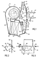
- the device shown in Figure 1 comprises a housing 10 housing an air blower 12 provided with a turbine 14 suitable for be rotated about an axis 16 by a motor electric (not shown).
- the turbine 14 is housed in a case 18 in the form of a scroll with a tangential outlet 20.
- the turbine 14 is suitable for being supplied axially by an air flow taken from outside and / or inside of the passenger compartment of the vehicle to produce a forced air flow (arrow F1) which leaves the casing 18 in the form of a volute by exit 20.
- the air flow F1 then successively passes through a filter 22, an evaporator 24 connected to an air conditioning circuit conventional, and a heating radiator 26.
- the radiator 26 is capable of being traversed by a heat transfer fluid which is usually the engine coolant the vehicle.
- This fluid enters the radiator 26 through a tube 28 controlled by an adjustable valve 30 and leaves the radiator 26 by an outlet pipe 32. It is thus possible produce, at the outlet of the heating radiator 26, a flow of air F2 at adjustable temperature.
- This air flow opens into a distribution chamber 34 of generally cylindrical shape, at least partly circular, delimited by a wall cylindrical 36 whose generators are parallel and equal distance from an X-X axis.
- the distribution chamber 34 is provided with an air inlet 38 (which is connected to the output of the heating radiator 26) and which supplies the chamber 34 with the air flow F2 at adjustable temperature.
- the distribution chamber 34 is in additionally provided with three air outlets located at its periphery, namely a defrost outlet 40, a ventilation outlet 42 and a 44 feet outlet.
- the defrost outlet 40 feeds an air outlet nozzle 46 which is formed directly with the housing 10. This nozzle 46 is suitable for defrosting / demisting the windshield vehicle.
- the output 42 feeds at least one ventilation nozzle (not shown) located on the dashboard of the vehicle.
- the output feet 44 feeds at least one nozzle (not shown) located in the lower part of the passenger compartment for send treated air to the area of the occupants' feet of the motor vehicle.
- a flap 46 of special structure which is pivotally mounted around the X-X axis.
- This component is a butterfly type component comprising a first wing 48 and a second wing 50 ( Figures 1 to 3) generally rectangular, located in the same plane, on either side of a shaft 52 extending in the direction of the X-X axis.
- a radial lever 54 ( Figures 2 and 3) which can be actuated by a connecting rod (not shown) connected to a control panel housed in the vehicle dashboard.
- the first wing 48 is suitable for controlling the defrost outlet 40, while the second wing 50 is specific to check the ventilation outlet 42 and the feet outlet 44.
- the wings 48 and 50 are provided, at their periphery, with a seal seal 56 which is overmolded ( Figure 2).
- the flap 46 is provided with an arch-shaped portion 58, which we can also call "drum part".
- This part 58 comprises a closure wall 60 (figures 1 to 3) defined by generatrices parallel to the axis of X-X pivoting of the shutter.
- This wall is a cylindrical wall partially circular centered on the pivot axis X-X and extending over an angular interval close to 45 ° (figure 2).
- the closure wall 60 is connected to the wings 48 and 50 of the flap 46 by two flanges 62 which are parallel between them and are attached perpendicularly to the wings 48 and 50.
- the arch-shaped part 58 thus delimits a passage interior 64 ( Figure 2) which channels the air flow F2.
- the main function of the closure wall 60 is to close, at least in part, the outlet feet 44 when the flap 46 is in a predefined position (FIG. 7), that is to say when this flap is in a position extreme, or at least in the vicinity of this position extreme.
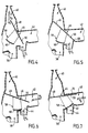
- the flap 46 can take a first extreme position, called “defrost position”, as shown in Figure 1, and a second extreme position, called “ventilation position”, as shown in Figure 7, passing through positions intermediates, as shown in Figures 4, 5 and 6.
- the flap In the intermediate position, called “defrost-feet position" in Figure 4, the flap has pivoted slightly by relative to the previous position (in the example in the sense anti-clockwise). Wing 48 partially opens the air outlet 40, while wing 50 partially opens the outlet feet 44. On the other hand, the ventilation outlet 42 is practically closed. Thus, the air flow F2 is divided into a flow F3 crossing the ventilation outlet 40 and a flow F4 crossing the feet outlet 44.
- the flap 46 has again pivoted relative to the previous position (always in the direction anti-clockwise).
- the wing 48 closes the outlet defrost 40
- wing 50 closes the ventilation outlet 42.
- the end of the wing 50 cooperates with sealing with a re-entrant edge 68 formed by the housing between the air outlets 42 and 44. Only a flow F4 crosses the outlet feet 44.
- the flap In the position of FIG. 6, the flap has again pivoted by relative to the previous position (always counterclockwise). In this position, the flap wing 48 ensures always closing the ventilation outlet 40, the end of the wing 48 coming to cooperate in sealing with the wall 36 of the distribution chamber 34. In this same position, the wing 50 opens the ventilation outlet 42 and the feet outlet 44, which are supplied with air as shown respectively by arrows F5 and F4.
- the wing 50 In the position of figure 7, which corresponds to another extreme position of the flap, the wing 50 is in abutment against a wall 70 of the housing which is substantially perpendicular to the wall 66. In this position, the wing 48 of the flap ensures always closing the defrost outlet 40, while the wing 50 ensures the opening of the ventilation outlet 42. By against, the closing wall 60 of the shaped portion 58 arch ensures the closure of the outlet feet 44.
- the air flow F2 feeds only the ventilation outlet 42, as shown by arrow F5.
- the air flow passes through the passage 64 of part 58 in the shape of an arch.
- closure wall 60 allows close more or less the 44 feet outlet and provide thus a multiplicity of intermediate positions between those of Figures 6 and 7 to provide precise adjustment of the air distribution between the ventilation outlet 42 and the output feet 44, which would not allow a butterfly flap classic.
- the second wing 50 of the flap 46 is provided, at its end, with a section of circular cylindrical wall 72 centered on the axis of X-X rotation of the flap and extending from the side opposite the part 58 in the shape of an arch.
- the flap 46 can occupy the five positions shown on Figure 8: defrost (1), defrost-feet (2), feet (3), foot ventilation (4) and ventilation (5).
- the ventilation position is shown in solid lines and the others in broken lines.
- the wall section 72 is intended to engage in a housing 74 formed in the wall 70 of the housing, which delimits the ventilation outlet 42 (FIG. 8).
- this accommodation 74 is produced in the form of a groove which is intended to accommodate the wall section 72 when the flap 46 is in the ventilation position.
- the air flow F2 feeds only the ventilation outlet 42, as shown by the arrow F5. Since the raised edge 72 is received in the housing 74, this prevents any passage of air towards the outlet defrost 40.
- the wing 48 of the flap 46 bears against a stop 76 (FIG. 8) formed in a wall delimiting the defrost outlet 40, which also helps to prevent the passage of an air flow to the defrost outlet 40.
- the wall section 72 cooperates with an interior wall 80 of the housing ( Figure 9) which extends between the ventilation outlet 42 and the outlet feet 44 and which has a cylindrical shape circular centered on axis XX.
- the wall section 72 is flush with the wall 80 in providing a seal, preventing any passage of air towards the ventilation outlet 42. If the wall section 72 was not not present, air leakage could occur through ventilation outlet in certain intermediate positions of the shutter for which air is not desired passes to the ventilation outlet.
- the distribution chamber 34 could, as a variant, constitute a mixing chamber fed by an air flow cold and a flow of hot air.
- the arch-shaped part, or drum part provides a better mixture of cold air / hot air and therefore reduce the temperature differences between the air outlets provided respectively in the upper part and in lower part of the case.
- the invention is not limited to a butterfly flap comprising a single arch-shaped part.
Abstract
Description
L'invention concerne un dispositif de distribution d'air pour le chauffage et/ou la climatisation de l'habitacle d'un véhicule.The invention relates to an air distribution device for the heating and / or air conditioning of the passenger compartment of a vehicle.
Elle concerne plus particulièrement un dispositif du type comprenant une chambre de distribution de forme générale cylindrique, munie d'une entrée d'air et d'au moins trois sorties d'air situées en périphérie de la chambre de distribution, ainsi qu'un volet papillon monté pivotant autour d'un axe à l'intérieur de la chambre de distribution pour contrôler la distribution de l'air par les sorties d'air.It relates more particularly to a device of the type comprising a distribution chamber of general shape cylindrical, with an air inlet and at least three air outlets located on the periphery of the distribution chamber, as well as a butterfly flap mounted to pivot around a axis inside the distribution chamber to control air distribution through the air outlets.
On connaít déjà, d'après la publication GB-A-2 077 417, un dispositif de ce type qui sert à la distribution d'air de ventilation dans l'habitacle d'un véhicule. Dans ce dispositif connu, la chambre de distribution est reliée à trois sorties d'air, à savoir une sortie dégivrage propre à alimenter des buses de dégivrage/désembuage du pare-brise, une sortie aération propre à alimenter des buses d'aération prévues sur la planche de bord du véhicule, et une sortie pieds propre à alimenter des buses dirigées vers la partie inférieure de l'habitacle du véhicule.We already know, from the publication GB-A-2 077 417, a device of this type which serves to distribute air from ventilation in the passenger compartment of a vehicle. In this device known, the distribution chamber is connected to three air outlets, i.e. a defrost outlet specific to supply defrost / demister nozzles to the windscreen, a ventilation outlet suitable for supplying ventilation nozzles provided on the dashboard of the vehicle, and an outlet feet suitable for supplying nozzles directed towards the part lower part of the vehicle interior.
Ce dispositif a notamment pour inconvénient que le volet doit pivoter d'un intervalle angulaire important (proche de 180°) entre ses deux positions extrêmes, ce qui nuit à la compacité du dispositif.This device has the particular disadvantage that the flap must rotate a large angular interval (close to 180 °) between its two extreme positions, which affects compactness of the device.
Par ailleurs, ce dispositif connu ne permet pas d'assurer un réglage précis de la distribution pour certaines positions du volet.Furthermore, this known device does not provide a precise adjustment of the distribution for certain positions of the shutter.
En outre, dans ce dispositif connu, la chambre de distribution constitue aussi une chambre de mixage dans laquelle se mélangent un flux d'air froid et un flux d'air chaud, en proportions réglables, pour fournir un réglage de la température de l'air à distribuer.In addition, in this known device, the distribution chamber also constitutes a mixing chamber in which mix a cold air flow and a hot air flow, adjustable proportions, to provide temperature control air to distribute.
Or, dans ce dispositif connu, le volet papillon ne permet pas un mélange intime de ces deux flux d'air, du moins pour certaines positions du volet.However, in this known device, the butterfly flap does not allow an intimate mixture of these two air flows, at least for certain positions of the shutter.
L'invention a notamment pour but de surmonter les inconvénients précités.The object of the invention is in particular to overcome the drawbacks cited above.
Elle propose à cet effet un dispositif de distribution d'air du type défini en introduction, dans lequel le volet est muni d'au moins une partie en forme d'arche comprenant une paroi d'obturation définie par des génératrices parallèles à l'axe de pivotement du volet, ladite paroi d'obturation étant reliée au volet par deux flasques espacés, en sorte que la paroi d'obturation et les deux flasques délimitent conjointement un passage d'air et que la paroi d'obturation est propre à fermer, au moins en partie, l'une des trois sorties d'air lorsque le volet se trouve dans une position définie.To this end, it offers an air distribution device of the type defined in the introduction, in which the shutter is provided at least one arch-shaped part comprising a wall shutter defined by generators parallel to the axis pivoting of the shutter, said closure wall being connected to the flap by two spaced flanges, so that the sealing wall and the two flanges jointly delimit an air passage and that the sealing wall is clean to close, at least in part, one of the three air outlets when the shutter is in a defined position.
Ainsi, le volet de l'invention constitue ce que l'on peut appeler un "volet mixte" comprenant un volet papillon combiné à une arche, que l'on peut encore appeler "partie tambour".Thus, the component of the invention constitutes what can be call a "mixed flap" including a combined butterfly flap to an arch, which can also be called "drum part".
Cette partie en forme d'arche permet d'obturer plus ou moins une des trois sorties d'air, tandis que le volet papillon permet de régler la distribution entre les deux autres sorties d'air, ce qui permet de procurer un réglage précis de la distribution.This arch-shaped part allows you to close more or less one of the three air outlets, while the butterfly flap adjusts the distribution between the other two air outlets, allowing precise adjustment of the distribution.
Par ailleurs, le volet du dispositif de l'invention permet de répartir la distribution entre trois sorties d'air, et cela avec un angle de débattement généralement voisin de 90°, ce qui permet de limiter l'encombrement.Furthermore, the flap of the device of the invention makes it possible to distribute the distribution between three air outlets, and this with a deflection angle generally close to 90 °, this which allows to limit the size.
De plus, le passage d'air défini par la partie en forme d'arche contribue à un meilleur mélange du flux d'air froid et du flux d'air chaud, lorsque la chambre de distribution constitue une chambre de mixage.In addition, the air passage defined by the shaped part arch contributes to a better mixture of cold air flow and the hot air flow, when the distribution chamber constitutes a mixing chamber.
Dans une forme de réalisation préférée de l'invention, la paroi d'obturation est une paroi cylindrique partiellement circulaire centrée sur l'axe de pivotement du volet. Cette paroi cylindrique s'étend avantageusement sur un intervalle angulaire inférieur à 45°.In a preferred embodiment of the invention, the end wall is a partially cylindrical wall circular centered on the pivot axis of the flap. This cylindrical wall advantageously extends over an interval angular less than 45 °.
Selon une autre caractéristique de l'invention, les flasques de la partie en forme d'arche se rattachent perpendiculairement au volet.According to another characteristic of the invention, the flanges of the arch-shaped part attach perpendicularly at the shutter.
Avantageusement, ces flasques se rattachent aux deux ailes que comporte le volet.Advantageously, these flanges are attached to the two wings that includes the shutter.
Pour améliorer le fonctionnement, l'invention prévoit que le volet soit muni d'un joint d'étanchéité périphérique.To improve operation, the invention provides that the flap is fitted with a peripheral seal.
Toutefois, la présence d'un joint d'étanchéité n'est généralement pas nécessaire sur la partie en forme d'arche.However, the presence of a seal is generally not not necessary on the arch-shaped part.
Dans une application de l'invention, les trois sorties d'air comprennent une sortie dégivrage, une sortie aération et une sortie pieds.In one application of the invention, the three air outlets include a defrost outlet, a ventilation outlet and a feet outlet.
En pareil cas, la paroi d'obturation de la partie en forme d'arche est avantageusement propre à obturer la sortie pieds dans ladite position définie du volet.In such a case, the sealing wall of the shaped part arch is advantageously suitable for closing the foot outlet in said defined position of the flap.
Cette position définie correspond de préférence à une position aération dans laquelle la sortie dégivrage est fermée par une première aile du volet et la sortie aération est ouverte par une deuxième aile du volet, la sortie aération étant alimentée par un flux d'air traversant le passage délimité par la partie en forme d'arche. This defined position preferably corresponds to a ventilation position in which the defrost outlet is closed by a first wing of the flap and the ventilation outlet is opened by a second wing of the flap, the outlet ventilation being supplied by an air flow passing through the passage delimited by the arch-shaped part.
Selon une autre caractéristique de l'invention, cette position définie, ou position d'aération, constitue une première position extrême du volet.According to another characteristic of the invention, this defined position, or ventilation position, constitutes a first extreme position of the flap.
De façon préférentielle, le volet est susceptible de prendre une deuxième position extrême dans laquelle la première aile du volet ouvre la sortie dégivrage, tandis que la deuxième aile du volet ferme la sortie aération et la sortie pieds, qui sont adjacentes.Preferably, the component is likely to take a second extreme position in which the first wing of the shutter opens the defrost outlet, while the second wing of the shutter closes the ventilation outlet and the feet outlet, which are adjacent.
Dans une variante de réalisation, la deuxième aile du volet est munie à son extrémité d'un tronçon de paroi cylindrique circulaire, centré sur l'axe de rotation du volet et s'étendant du côté opposé à la partie en forme d'arche, ledit tronçon de paroi étant propre à coopérer, dans une position intermédiaire du volet, avec une paroi interne du boítier qui s'étend entre la sortie aération et la sortie pieds.In an alternative embodiment, the second wing of the flap has a cylindrical wall section at its end circular, centered on the axis of rotation of the shutter and extending on the side opposite the arch-shaped part, said wall section being able to cooperate, in a position intermediate of the flap, with an internal wall of the housing which extends between the ventilation outlet and the feet outlet.
Ce tronçon de paroi cylindrique circulaire, qui forme portée cylindrique, permet principalement d'empêcher un passage d'air vers la sortie aération lorsque le volet passe d'une position pieds à une position dégivrage-pieds.This section of circular cylindrical wall, which forms bearing cylindrical, mainly to prevent passage air to the ventilation outlet when the flap passes from one feet position to a defrost-feet position.
Avantageusement, le tronçon de paroi cylindrique circulaire est propre à s'engager, dans la position aération, dans un logement en forme de rainure, formé dans une paroi du boítier qui délimite la sortie aération. Ceci permet d'éviter un passage d'air vers la sortie dégivrage.Advantageously, the circular cylindrical wall section is suitable for engaging, in the ventilation position, in a groove-shaped housing, formed in a wall of the housing which defines the ventilation outlet. This avoids a air passage to the defrost outlet.
Dans l'application particulière précitée, le volet possède avantageusement un débattement angulaire, entre la première et la deuxième position extrême, qui est d'environ un quart de tour.In the particular application mentioned above, the shutter has advantageously an angular movement, between the first and the second extreme position, which is about a quarter of turn.
Dans cette application particulière, le volet peut prendre au moins trois positions intermédiaires :
- une position dégivrage-pieds dans laquelle la sortie dégivrage et la sortie pieds sont partiellement ouvertes, alors que la sortie aération est fermée;
- une position pieds dans laquelle la sortie pieds est ouverte alors que la sortie dégivrage et la sortie aération sont fermées; et
- une position aération-pieds dans laquelle la sortie aération et la sortie pieds sont ouvertes, alors que la sortie dégivrage est fermée.
- a defrost-feet position in which the defrost outlet and the feet outlet are partially open, while the ventilation outlet is closed;
- a feet position in which the feet outlet is open while the defrost outlet and the ventilation outlet are closed; and
- a foot ventilation position in which the ventilation outlet and the feet outlet are open, while the defrost outlet is closed.
Dans la description qui suit, faite seulement à titre d'exemple, on se réfère aux dessins annexés, sur lesquels :
- la figure 1 est une vue en coupe transversale d'un boítier d'un appareil de chauffage et/ou climatisation de véhicule automobile comprenant un dispositif de distribution d'air selon l'invention, le volet du dispositif étant représenté dans une position extrême dite "position dégivrage";
- la figure 2 est une vue en coupe du volet, le plan de coupe étant perpendiculaire à l'axe de pivotement du volet;
- la figure 3 est une vue en perspective du volet des figures 1 et 2;
- les figures 4, 5 et 6 sont des vues partielles, analogues à la figure 1, montrant trois positions intermédiaires du volet;
- la figure 7 est une vue analogue aux figures 4, 5 et 6, le volet étant représenté dans une autre position extrême dite "position aération";
- la figure 8 est une vue analogue à la figure 7 dans une variante de réalisation, le volet étant représenté en "position aération" ;
- la figure 9 est une vue analogue à la figure 8, dans laquelle le volet est représenté dans une position intermédiaire comprise entre une "position pieds" et une position "dégivrage-pieds" ; et
- la figure 10 est une vue en perspective du volet correspondant à la variante de réalisation des figures 8 et 9.
- Figure 1 is a cross-sectional view of a housing of a motor vehicle heating and / or air conditioning unit comprising an air distribution device according to the invention, the flap of the device being shown in an extreme position called "defrost position";
- Figure 2 is a sectional view of the shutter, the cutting plane being perpendicular to the pivot axis of the shutter;
- Figure 3 is a perspective view of the shutter of Figures 1 and 2;
- Figures 4, 5 and 6 are partial views, similar to Figure 1, showing three intermediate positions of the flap;
- Figure 7 is a view similar to Figures 4, 5 and 6, the flap being shown in another extreme position called "ventilation position";
- Figure 8 is a view similar to Figure 7 in an alternative embodiment, the flap being shown in "ventilation position";
- Figure 9 is a view similar to Figure 8, in which the flap is shown in an intermediate position between a "feet position" and a "defrost-feet"position; and
- FIG. 10 is a perspective view of the flap corresponding to the variant embodiment of FIGS. 8 and 9.
Le dispositif représenté à la figure 1 comprend un boítier 10
logeant un pulseur d'air 12 muni d'une turbine 14 propre à
être entraínée en rotation autour d'un axe 16 par un moteur
électrique (non représenté). La turbine 14 est logée dans un
boítier 18 en forme de volute muni d'une sortie tangentielle
20. La turbine 14 est propre à être alimentée axialement
par un flux d'air prélevé à l'extérieur et/ou à l'intérieur
de l'habitacle du véhicule pour produire un flux d'air pulsé
(flèche F1) qui quitte le boítier 18 en forme de volute par
la sortie 20.The device shown in Figure 1 comprises a
Le flux d'air F1 traverse ensuite successivement un filtre
22, un évaporateur 24 relié à un circuit de climatisation
classique, et un radiateur de chauffage 26. Le radiateur 26
est propre à être parcouru par un fluide caloporteur qui est
généralement le liquide de refroidissement du moteur du
véhicule.The air flow F1 then successively passes through a
Ce fluide pénètre dans le radiateur 26 par une tubulure
d'entrée 28 contrôlée par un robinet réglable 30 et quitte le
radiateur 26 par une tubulure de sortie 32. On peut ainsi
produire, à la sortie du radiateur de chauffage 26, un flux
d'air F2 à température réglable. Ce flux d'air débouche dans
une chambre de distribution 34 de forme générale cylindrique,
au moins en partie circulaire, délimitée par une paroi
cylindrique 36 dont les génératrices sont parallèles et à
égale distance d'un axe X-X.This fluid enters the
La chambre de distribution 34 est munie d'une entrée d'air 38
(qui est reliée à la sortie du radiateur de chauffage 26) et
qui permet d'alimenter la chambre 34 par le flux d'air F2 à
température réglable. La chambre de distribution 34 est en
outre munie de trois sorties d'air situées à sa périphérie,
à savoir une sortie dégivrage 40, une sortie aération 42 et
une sortie pieds 44.The distribution chamber 34 is provided with an air inlet 38
(which is connected to the output of the heating radiator 26) and
which supplies the chamber 34 with the air flow F2 at
adjustable temperature. The distribution chamber 34 is in
additionally provided with three air outlets located at its periphery,
namely a
La sortie dégivrage 40 alimente une buse de sortie d'air 46
qui est formée directement avec le boítier 10. Cette buse 46
est propre à assurer le dégivrage/désembuage du pare-brise du
véhicule. La sortie 42 alimente au moins une buse d'aération
(non représentée) située sur la planche de bord du véhicule.
Enfin, la sortie pieds 44 alimente au moins une buse (non
représentée) située en partie inférieure de l'habitacle pour
envoyer de l'air traité dans la région des pieds des occupants
du véhicule automobile.The
Dans la chambre de distribution 34 est logé un volet 46 de
structure particulière, qui est monté pivotant autour de
l'axe X-X. Ce volet est un volet de type papillon comprenant
une première aile 48 et une deuxième aile 50 (figures 1 à 3)
de forme générale rectangulaire, situées dans un même plan,
de part et d'autre d'un arbre 52 s'étendant dans la direction
de l'axe X-X.In the distribution chamber 34 is housed a
A une extrémité de l'arbre 52 est calé un levier radial 54
(figures 2 et 3) qui peut être actionné par une bielle (non
représentée) reliée à un tableau de commande logé dans la
planche de bord du véhicule.At one end of the
La première aile 48 est propre à contrôler la sortie dégivrage
40, tandis que la deuxième aile 50 est propre à
contrôler la sortie aération 42 et la sortie pieds 44. Les
ailes 48 et 50 sont munies, à leur périphérie, d'un joint
d'étanchéité 56 qui est surmoulé (figure 2).The
Le volet 46 est muni d'une partie 58 en forme d'arche, que
l'on peut encore appeler "partie tambour".The
Cette partie 58 comprend une paroi d'obturation 60 (figures
1 à 3) définie par des génératrices parallèles à l'axe de
pivotement X-X du volet. Cette paroi est une paroi cylindrique
partiellement circulaire centrée sur l'axe de pivotement
X-X et s'étendant sur un intervalle angulaire voisin de 45°
(figure 2). La paroi d'obturation 60 est reliée aux ailes 48
et 50 du volet 46 par deux flasques 62 qui sont parallèles
entre eux et se rattachent perpendiculairement aux ailes 48
et 50.This
La partie 58 en forme d'arche délimite ainsi un passage
intérieur 64 (figure 2) qui permet de canaliser le flux d'air
F2.The arch-shaped
La paroi d'obturation 60 a pour fonction principale de
fermer, au moins en partie, la sortie pieds 44 lorsque le
volet 46 se trouve dans une position prédéfinie (figure 7),
c'est-à-dire lorsque ce volet se trouve dans une position
extrême, ou tout au moins au voisinage de cette position
extrême.The main function of the
Le volet 46 peut prendre une première position extrême, dite
"position dégivrage", comme représenté à la figure 1, et une
deuxième position extrême, dite "position aération", comme
représenté à la figure 7, en passant par des positions
intermédiaires, comme représenté sur les figures 4, 5 et 6.The
Dans la position de la figure 1, l'aile 48 du volet est en
appui contre une paroi 66 du boítier et ouvre complètement la
sortie dégivrage 40. Par contre, l'aile 50 ferme à la fois la
sortie aération 42 et la sortie pieds 44. Le flux d'air F2
traverse le passage 64 de la partie 58 en forme d'arche pour
quitter la chambre de distribution par la sortie dégivrage 40
comme montré par la flèche F3.In the position of Figure 1, the
Dans la position intermédiaire, dite "position dégivrage-pieds"
de la figure 4, le volet a pivoté légèrement par
rapport à la position précédente (dans l'exemple dans le sens
anti-horaire). L'aile 48 ouvre partiellement la sortie d'air
40, tandis que l'aile 50 entrouvre partiellement la sortie
pieds 44. Par contre, la sortie aération 42 est pratiquement
fermée. Ainsi, le flux d'air F2 est divisé en un flux F3
traversant la sortie aération 40 et un flux F4 traversant la
sortie pieds 44.In the intermediate position, called "defrost-feet position"
in Figure 4, the flap has pivoted slightly by
relative to the previous position (in the example in the sense
anti-clockwise).
Dans la position de la figure 5, le volet 46 a encore pivoté
par rapport à la position précédente (toujours dans le sens
anti-horaire). Il en résulte que l'aile 48 ferme la sortie
dégivrage 40, tandis que l'aile 50 ferme la sortie aération
42. L'extrémité de l'aile 50 vient coopérer à étanchéité
avec un bord rentrant 68 formé par le boítier entre les
sorties d'air 42 et 44. Seul un flux F4 traverse la sortie
pieds 44.In the position of FIG. 5, the
Dans la position de la figure 6, le volet a encore pivoté par
rapport à la position précédente (toujours dans le sens anti-horaire).
Dans cette position, l'aile 48 du volet assure
toujours la fermeture de la sortie aération 40, l'extrémité
de l'aile 48 venant coopérer à étanchéité avec la paroi 36 de
la chambre de distribution 34. Dans cette même position,
l'aile 50 ouvre la sortie aération 42 et la sortie pieds 44,
lesquelles sont alimentées en air comme montré respectivement
par les flèches F5 et F4.In the position of FIG. 6, the flap has again pivoted by
relative to the previous position (always counterclockwise).
In this position, the
Dans la position de la figure 7, qui correspond à une autre
position extrême du volet, l'aile 50 est en appui contre une
paroi 70 du boítier qui est sensiblement perpendiculaire à la
paroi 66. Dans cette position, l'aile 48 du volet assure
toujours la fermeture de la sortie dégivrage 40, tandis que
l'aile 50 assure l'ouverture de la sortie aération 42. Par
contre, la paroi d'obturation 60 de la partie 58 en forme
d'arche assure la fermeture de la sortie pieds 44. Ainsi, le
flux d'air F2 alimente uniquement la sortie aération 42,
comme montré par la flèche F5. Le flux d'air traverse le
passage 64 de la partie 58 en forme d'arche.In the position of figure 7, which corresponds to another
extreme position of the flap, the
Il est à noter toutefois que la paroi d'obturation 60 permet
d'obturer plus ou moins la sortie pieds 44 et de procurer
ainsi une multiplicité de positions intermédiaires entre
celles des figures 6 et 7 pour fournir un réglage précis de
la distribution d'air entre la sortie aération 42 et la
sortie pieds 44, ce que ne permettrait pas un volet papillon
classique.It should be noted however that the
Dans la forme de réalisation des figures 8 à 10, la deuxième
aile 50 du volet 46 est munie, à son extrémité, d'un tronçon
de paroi cylindrique circulaire 72 centré sur l'axe de
rotation X-X du volet et s'étendant du côté opposé à la
partie 58 en forme d'arche.In the embodiment of Figures 8 to 10, the
Le volet 46 peut occuper les cinq positions représentées sur
la figure 8 : dégivrage (1), dégivrage-pieds (2), pieds (3),
aération-pieds (4) et aération (5). La position aération est
représentée en trait plein et les autres en trait interrompu.The
Le tronçon de paroi 72 est destiné à s'engager dans un
logement 74 formé dans la paroi 70 du boítier, qui délimite
la sortie aération 42 (figure 8). Dans l'exemple, ce logement
74 est réalisé sous la forme d'une rainure qui est destinée
à accueillir le tronçon de paroi 72 lorsque le volet 46 est
dans la position d'aération. Dans cette position (qui
correspond à celle de la figure 7), le flux d'air F2 alimente
uniquement la sortie aération 42, comme montré par la flèche
F5. Etant donné que le bord relevé 72 est reçu dans le
logement 74, cela empêche tout passage d'air vers la sortie
dégivrage 40. Par ailleurs, dans cette position, l'aile 48 du
volet 46 est en appui contre une butée 76 (figure 8) formée
dans une paroi délimitant la sortie dégivrage 40, ce qui
contribue aussi à empêcher le passage d'un flux d'air vers la
sortie dégivrage 40.The
Dans l'autre position extrême, ou position dégivrage (position
1), l'aile 48 du volet vient en appui contre une autre
butée 78 qui limite le débattement angulaire du volet.In the other extreme position, or defrost position (position
1), the
Lorsque le volet passe de la position pieds (position 3) à la
position dégivrage-pieds (position 2), ou inversement, la
tronçon de paroi 72 vient coopérer avec une paroi intérieure
80 du boítier (figure 9) qui s'étend entre la sortie aération
42 et la sortie pieds 44 et qui présente une forme cylindrique
circulaire centrée sur l'axe XX.When the flap goes from the feet position (position 3) to the
defrost-feet position (position 2), or vice versa, the
Le tronçon de paroi 72 vient affleurer la paroi 80 en
procurant une étanchéité, ce qui empêche tout passage d'air
vers la sortie aération 42. Si le tronçon de paroi 72 n'était
pas présent, une fuite d'air pourrait se produire par la
sortie aération dans certaines positions intermédiaires du
volet pour lesquelles il n'est pas souhaité que de l'air
passe vers la sortie aération.The
Bien entendu, l'invention n'est pas limitée aux formes de réalisation décrites précédemment à titre d'exemple.Of course, the invention is not limited to the forms of realization described previously by way of example.
Ainsi, la chambre de distribution 34 pourrait, en variante, constituer une chambre de mixage alimentée par un flux d'air froid et un flux d'air chaud.Thus, the distribution chamber 34 could, as a variant, constitute a mixing chamber fed by an air flow cold and a flow of hot air.
En pareil cas, la partie en forme d'arche, ou partie tambour, permet d'obtenir un meilleur mélange air froid/air chaud et par conséquent de réduire les écarts de température entre les sorties d'air prévues respectivement en partie haute et en partie basse du boítier.In such a case, the arch-shaped part, or drum part, provides a better mixture of cold air / hot air and therefore reduce the temperature differences between the air outlets provided respectively in the upper part and in lower part of the case.
De plus, l'invention n'est pas limitée à un volet papillon comportant une seule partie en forme d'arche.In addition, the invention is not limited to a butterfly flap comprising a single arch-shaped part.
Claims (14)
caractérisé en ce que le volet (46) est muni d'au moins une partie (58) en forme d'arche comprenant une paroi d'obturation (60) définie par des génératrices parallèles à l'axe de pivotement (X-X) du volet, ladite paroi d'obturation (60) étant reliée au volet par deux flasques espacés (62), en sorte que la paroi d'obturation (60) et les deux flasques (62) délimitent conjointement un passage d'air (64), et que la paroi d'obturation (60) est propre à fermer, au moins en partie, l'une (44) des trois sorties d'air lorsque le volet (46) se trouve dans une position définie.Air distribution device for heating and / or air conditioning the passenger compartment of a vehicle, comprising a distribution chamber (34) of generally cylindrical shape, provided with an air inlet (38) and at least three air outlets (40, 42, 44) located on the periphery of the distribution chamber, as well as a butterfly flap (46) pivotally mounted about an axis (XX) inside the distribution (34) to control the distribution of air through the air outlets,
characterized in that the flap (46) is provided with at least one arch-shaped part (58) comprising a closure wall (60) defined by generatrices parallel to the pivot axis (XX) of the flap , said closure wall (60) being connected to the flap by two spaced flanges (62), so that the closure wall (60) and the two flanges (62) jointly delimit an air passage (64), and that the closure wall (60) is capable of closing, at least in part, one (44) of the three air outlets when the flap (46) is in a defined position.
Applications Claiming Priority (2)
| Application Number | Priority Date | Filing Date | Title |
|---|---|---|---|
| FR9703273A FR2761012B1 (en) | 1997-03-18 | 1997-03-18 | AIR DISTRIBUTION DEVICE FOR HEATING AND / OR AIR CONDITIONING THE INTERIOR OF A VEHICLE |
| FR9703273 | 1997-03-18 |
Publications (2)
| Publication Number | Publication Date |
|---|---|
| EP0865945A1 true EP0865945A1 (en) | 1998-09-23 |
| EP0865945B1 EP0865945B1 (en) | 2002-08-21 |
Family
ID=9504910
Family Applications (1)
| Application Number | Title | Priority Date | Filing Date |
|---|---|---|---|
| EP19980400607 Expired - Lifetime EP0865945B1 (en) | 1997-03-18 | 1998-03-16 | Air distributing device for heating and/or air-conditioning the interior of a vehicle |
Country Status (4)
| Country | Link |
|---|---|
| EP (1) | EP0865945B1 (en) |
| BR (1) | BR9800918A (en) |
| DE (1) | DE69807275T2 (en) |
| FR (1) | FR2761012B1 (en) |
Cited By (11)
| Publication number | Priority date | Publication date | Assignee | Title |
|---|---|---|---|---|
| FR2789017A1 (en) * | 1999-01-29 | 2000-08-04 | Valeo Climatisation | Air distributor for motor vehicle interior has fan mounted around transverse axis with central aeration duct |
| DE10052135A1 (en) * | 2000-10-20 | 2002-05-02 | Valeo Klimasysteme Gmbh | Air duct housing |
| EP1306240A2 (en) | 2001-10-24 | 2003-05-02 | Behr GmbH & Co. | Airflow control apparatus |
| FR2833530A1 (en) * | 2001-12-18 | 2003-06-20 | Valeo Climatisation | Automobile air conditioning equipment comprises frame containing air propulsion means, first and second optional air heating means, de-icing conduit and an ventilation conduits for compartment top and bottom zones |
| CN100431864C (en) * | 2004-04-15 | 2008-11-12 | 瓦莱奥空调系统有限公司 | Air-guiding system for a ventilation system of a vehicle |
| EP2407324A1 (en) * | 2010-07-16 | 2012-01-18 | Behr France Rouffach SAS | Air regulator element for a heating and ventilation device for a motor vehicle and heating and ventilation device for a passenger area of a motor vehicle |
| EP2679417A1 (en) * | 2012-06-25 | 2014-01-01 | Valeo Autoklimatizace k.s. | Vehicle heating, ventilating and/or conditioning unit |
| US20150217629A1 (en) * | 2014-02-04 | 2015-08-06 | Calsonic Kansel Corporation | Vehicle air conditioner |
| EP2918431A1 (en) * | 2011-12-23 | 2015-09-16 | Valeo Systemes Thermiques | Casing of a heating, ventilation and/or air conditioning unit and shutter for such a casing |
| US20180141407A1 (en) * | 2016-11-23 | 2018-05-24 | Hyundai Motor Company | Air Conditioning Apparatus for Vehicle |
| US10106188B2 (en) | 2016-10-21 | 2018-10-23 | Hyundai Motor Company | Steering wheel cooling system |
Families Citing this family (2)
| Publication number | Priority date | Publication date | Assignee | Title |
|---|---|---|---|---|
| FR2821588B1 (en) * | 2001-03-02 | 2003-09-05 | Valeo Climatisation | HEATING AND / OR AIR-CONDITIONING ASSEMBLY EQUIPPED WITH MOBILE SHUTTERS FOR A COCKPIT OF A MOTOR VEHICLE AND VEHICLE THUS EQUIPPED |
| DE102011080214A1 (en) * | 2011-08-01 | 2013-02-07 | Behr Gmbh & Co. Kg | Heating or air conditioning apparatus for motor car, has air division device that is arranged in air-conditioned space on discharge openings to distribute air in air distribution housing from air duct arranged between fan and housing |
Citations (5)
| Publication number | Priority date | Publication date | Assignee | Title |
|---|---|---|---|---|
| GB2077417A (en) | 1980-02-27 | 1981-12-16 | Saab Scania Ab | Arrangement for distributing ventilation air in vehicles |
| US4947735A (en) * | 1988-05-27 | 1990-08-14 | Valeo | Distribution box for a heating and/or air conditioning apparatus, especially for an automotive vehicle |
| EP0423778A2 (en) * | 1989-10-20 | 1991-04-24 | BORLETTI CLIMATIZZAZIONE S.r.l. | A distributor for motor-vehicle air-conditioning systems |
| DE4305253A1 (en) * | 1993-02-20 | 1994-08-25 | Opel Adam Ag | Heating and ventilation device |
| FR2728515A1 (en) * | 1994-12-22 | 1996-06-28 | Valeo Thermique Habitacle | Air distribution duct for motor vehicle |
-
1997
- 1997-03-18 FR FR9703273A patent/FR2761012B1/en not_active Expired - Fee Related
-
1998
- 1998-03-16 DE DE1998607275 patent/DE69807275T2/en not_active Expired - Fee Related
- 1998-03-16 EP EP19980400607 patent/EP0865945B1/en not_active Expired - Lifetime
- 1998-03-17 BR BR9800918A patent/BR9800918A/en not_active IP Right Cessation
Patent Citations (5)
| Publication number | Priority date | Publication date | Assignee | Title |
|---|---|---|---|---|
| GB2077417A (en) | 1980-02-27 | 1981-12-16 | Saab Scania Ab | Arrangement for distributing ventilation air in vehicles |
| US4947735A (en) * | 1988-05-27 | 1990-08-14 | Valeo | Distribution box for a heating and/or air conditioning apparatus, especially for an automotive vehicle |
| EP0423778A2 (en) * | 1989-10-20 | 1991-04-24 | BORLETTI CLIMATIZZAZIONE S.r.l. | A distributor for motor-vehicle air-conditioning systems |
| DE4305253A1 (en) * | 1993-02-20 | 1994-08-25 | Opel Adam Ag | Heating and ventilation device |
| FR2728515A1 (en) * | 1994-12-22 | 1996-06-28 | Valeo Thermique Habitacle | Air distribution duct for motor vehicle |
Cited By (15)
| Publication number | Priority date | Publication date | Assignee | Title |
|---|---|---|---|---|
| US6296563B1 (en) | 1998-01-29 | 2001-10-02 | Valeo Climatisation | Device for the distribution of ventilation air in the passenger compartment of a motor vehicle |
| FR2789017A1 (en) * | 1999-01-29 | 2000-08-04 | Valeo Climatisation | Air distributor for motor vehicle interior has fan mounted around transverse axis with central aeration duct |
| DE10052135A1 (en) * | 2000-10-20 | 2002-05-02 | Valeo Klimasysteme Gmbh | Air duct housing |
| EP1306240A2 (en) | 2001-10-24 | 2003-05-02 | Behr GmbH & Co. | Airflow control apparatus |
| DE10152597A1 (en) * | 2001-10-24 | 2003-05-08 | Behr Gmbh & Co | Air flow control device |
| FR2833530A1 (en) * | 2001-12-18 | 2003-06-20 | Valeo Climatisation | Automobile air conditioning equipment comprises frame containing air propulsion means, first and second optional air heating means, de-icing conduit and an ventilation conduits for compartment top and bottom zones |
| CN100431864C (en) * | 2004-04-15 | 2008-11-12 | 瓦莱奥空调系统有限公司 | Air-guiding system for a ventilation system of a vehicle |
| US7462099B2 (en) * | 2004-04-15 | 2008-12-09 | Valeo Klimasysteme Gmbh | Air-guiding system for a ventilation system of a vehicle |
| EP2407324A1 (en) * | 2010-07-16 | 2012-01-18 | Behr France Rouffach SAS | Air regulator element for a heating and ventilation device for a motor vehicle and heating and ventilation device for a passenger area of a motor vehicle |
| EP2918431A1 (en) * | 2011-12-23 | 2015-09-16 | Valeo Systemes Thermiques | Casing of a heating, ventilation and/or air conditioning unit and shutter for such a casing |
| EP2679417A1 (en) * | 2012-06-25 | 2014-01-01 | Valeo Autoklimatizace k.s. | Vehicle heating, ventilating and/or conditioning unit |
| US20150217629A1 (en) * | 2014-02-04 | 2015-08-06 | Calsonic Kansel Corporation | Vehicle air conditioner |
| US10106188B2 (en) | 2016-10-21 | 2018-10-23 | Hyundai Motor Company | Steering wheel cooling system |
| US20180141407A1 (en) * | 2016-11-23 | 2018-05-24 | Hyundai Motor Company | Air Conditioning Apparatus for Vehicle |
| US10864797B2 (en) * | 2016-11-23 | 2020-12-15 | Hyundai Motor Company | Air conditioning apparatus for vehicle |
Also Published As
| Publication number | Publication date |
|---|---|
| BR9800918A (en) | 1999-09-14 |
| FR2761012B1 (en) | 1999-05-28 |
| DE69807275T2 (en) | 2003-04-17 |
| DE69807275D1 (en) | 2002-09-26 |
| EP0865945B1 (en) | 2002-08-21 |
| FR2761012A1 (en) | 1998-09-25 |
Similar Documents
| Publication | Publication Date | Title |
|---|---|---|
| EP1013491B1 (en) | Vehicle heating and/or air conditioning with improved air mixing | |
| EP0865945B1 (en) | Air distributing device for heating and/or air-conditioning the interior of a vehicle | |
| EP0812714B1 (en) | Heating and/or ventilation for a motor vehicle interior | |
| FR2726229A1 (en) | DEVICE FOR HEATING AND / OR AERATING THE INTERIOR OF A MOTOR VEHICLE | |
| EP0266230A1 (en) | Air conditioning device including an air mixing valve for vehicles and similar applications | |
| FR2720693A1 (en) | Device for heating and / or ventilating the passenger compartment of a vehicle. | |
| EP0656272B1 (en) | Distribution device for a motor vehicle air conditioning installation | |
| FR2788019A1 (en) | Air distributor for heater in vehicle passenger compartment comprises mixing chamber and three outlets controlled by two distribution flaps shaped as drums pivoting on single axis | |
| WO2020174146A1 (en) | Heating and/or ventilation and/or air conditioning system comprising a mixing flap with deflector | |
| FR2777512A1 (en) | AIR INTAKE BOX FOR A MOTOR VEHICLE HEATING AND / OR AIR CONDITIONING SYSTEM | |
| FR2766760A1 (en) | AIR DISTRIBUTION DEVICE FOR HEATING AND / OR AIR CONDITIONING THE INTERIOR OF A VEHICLE | |
| FR2746714A1 (en) | Control of heating and cooling of interior of motor vehicle | |
| FR2710878A1 (en) | Device for the heating and ventilation of the passenger compartment (cockpit) of a motor vehicle | |
| FR2761011A1 (en) | Adjustment device for air flow control in vehicle climate control system | |
| EP0749857B1 (en) | Device for heating and ventilating the interior of a vehicle | |
| WO1999055545A1 (en) | Heating and/or air conditioning device for a vehicle passenger compartment with improved air mixing | |
| FR2728515A1 (en) | Air distribution duct for motor vehicle | |
| FR2786134A1 (en) | Heating and ventilating assembly for vehicle passenger compartment comprises upper and lower branches with outlets sized to feed only heated air to lateral section of mixing zone. | |
| FR2679621A1 (en) | DEVICE FOR CONTROLLING SHUTTERS, ESPECIALLY SHUTTERS OF A VENTILATION AND / OR AIR CONDITIONING HEATER. | |
| FR2798322A1 (en) | Automobile heating and/or air conditioning system with improved air distribution has pipe fed with treated air, and mobile shutter controlling treated air | |
| WO2023126159A1 (en) | Sliding flap of a heating, ventilation and/or air-conditioning device for a passenger compartment of a vehicle | |
| FR2764550A1 (en) | Air ventilation system for vehicle passenger compartment | |
| FR2797810A1 (en) | Calibration of air inlet sections of vehicle air conditioning installation comprises air inlet box whose air inlet passage is adjusted by flap, box walls having angular segments accounting for flap drive mechanism tolerances | |
| FR2836541A1 (en) | Ventilation flap for automobile compartment comprises air distribution barrel able to rotate relative to casing between air flow position and air obturation position and rotating flap upstream of barrel | |
| FR2756512A3 (en) | Vehicle heating or air conditioning system |
Legal Events
| Date | Code | Title | Description |
|---|---|---|---|
| PUAI | Public reference made under article 153(3) epc to a published international application that has entered the european phase |
Free format text: ORIGINAL CODE: 0009012 |
|
| AK | Designated contracting states |
Kind code of ref document: A1 Designated state(s): DE FR |
|
| AX | Request for extension of the european patent |
Free format text: AL;LT;LV;MK;RO;SI |
|
| 17P | Request for examination filed |
Effective date: 19990216 |
|
| AKX | Designation fees paid |
Free format text: DE FR |
|
| RBV | Designated contracting states (corrected) |
Designated state(s): DE FR |
|
| 17Q | First examination report despatched |
Effective date: 20000314 |
|
| GRAG | Despatch of communication of intention to grant |
Free format text: ORIGINAL CODE: EPIDOS AGRA |
|
| GRAG | Despatch of communication of intention to grant |
Free format text: ORIGINAL CODE: EPIDOS AGRA |
|
| GRAH | Despatch of communication of intention to grant a patent |
Free format text: ORIGINAL CODE: EPIDOS IGRA |
|
| GRAH | Despatch of communication of intention to grant a patent |
Free format text: ORIGINAL CODE: EPIDOS IGRA |
|
| GRAA | (expected) grant |
Free format text: ORIGINAL CODE: 0009210 |
|
| AK | Designated contracting states |
Kind code of ref document: B1 Designated state(s): DE FR |
|
| REF | Corresponds to: |
Ref document number: 69807275 Country of ref document: DE Date of ref document: 20020926 |
|
| PGFP | Annual fee paid to national office [announced via postgrant information from national office to epo] |
Ref country code: DE Payment date: 20030312 Year of fee payment: 6 |
|
| PGFP | Annual fee paid to national office [announced via postgrant information from national office to epo] |
Ref country code: FR Payment date: 20030328 Year of fee payment: 6 |
|
| PLBE | No opposition filed within time limit |
Free format text: ORIGINAL CODE: 0009261 |
|
| STAA | Information on the status of an ep patent application or granted ep patent |
Free format text: STATUS: NO OPPOSITION FILED WITHIN TIME LIMIT |
|
| 26N | No opposition filed |
Effective date: 20030522 |
|
| PG25 | Lapsed in a contracting state [announced via postgrant information from national office to epo] |
Ref country code: DE Free format text: LAPSE BECAUSE OF NON-PAYMENT OF DUE FEES Effective date: 20041001 |
|
| PG25 | Lapsed in a contracting state [announced via postgrant information from national office to epo] |
Ref country code: FR Free format text: LAPSE BECAUSE OF NON-PAYMENT OF DUE FEES Effective date: 20041130 |
|
| REG | Reference to a national code |
Ref country code: FR Ref legal event code: ST |