EP2679020B1 - Sealant mold fixture for a domed cap - Google Patents
Sealant mold fixture for a domed cap Download PDFInfo
- Publication number
- EP2679020B1 EP2679020B1 EP12790036.3A EP12790036A EP2679020B1 EP 2679020 B1 EP2679020 B1 EP 2679020B1 EP 12790036 A EP12790036 A EP 12790036A EP 2679020 B1 EP2679020 B1 EP 2679020B1
- Authority
- EP
- European Patent Office
- Prior art keywords
- sealant
- mold
- substrate
- inner cap
- sealant mold
- Prior art date
- Legal status (The legal status is an assumption and is not a legal conclusion. Google has not performed a legal analysis and makes no representation as to the accuracy of the status listed.)
- Active
Links
Images


Classifications
-
- B—PERFORMING OPERATIONS; TRANSPORTING
- B29—WORKING OF PLASTICS; WORKING OF SUBSTANCES IN A PLASTIC STATE IN GENERAL
- B29C—SHAPING OR JOINING OF PLASTICS; SHAPING OF MATERIAL IN A PLASTIC STATE, NOT OTHERWISE PROVIDED FOR; AFTER-TREATMENT OF THE SHAPED PRODUCTS, e.g. REPAIRING
- B29C33/00—Moulds or cores; Details thereof or accessories therefor
-
- B—PERFORMING OPERATIONS; TRANSPORTING
- B29—WORKING OF PLASTICS; WORKING OF SUBSTANCES IN A PLASTIC STATE IN GENERAL
- B29C—SHAPING OR JOINING OF PLASTICS; SHAPING OF MATERIAL IN A PLASTIC STATE, NOT OTHERWISE PROVIDED FOR; AFTER-TREATMENT OF THE SHAPED PRODUCTS, e.g. REPAIRING
- B29C39/00—Shaping by casting, i.e. introducing the moulding material into a mould or between confining surfaces without significant moulding pressure; Apparatus therefor
- B29C39/02—Shaping by casting, i.e. introducing the moulding material into a mould or between confining surfaces without significant moulding pressure; Apparatus therefor for making articles of definite length, i.e. discrete articles
- B29C39/10—Shaping by casting, i.e. introducing the moulding material into a mould or between confining surfaces without significant moulding pressure; Apparatus therefor for making articles of definite length, i.e. discrete articles incorporating preformed parts or layers, e.g. casting around inserts or for coating articles
-
- B—PERFORMING OPERATIONS; TRANSPORTING
- B29—WORKING OF PLASTICS; WORKING OF SUBSTANCES IN A PLASTIC STATE IN GENERAL
- B29C—SHAPING OR JOINING OF PLASTICS; SHAPING OF MATERIAL IN A PLASTIC STATE, NOT OTHERWISE PROVIDED FOR; AFTER-TREATMENT OF THE SHAPED PRODUCTS, e.g. REPAIRING
- B29C39/00—Shaping by casting, i.e. introducing the moulding material into a mould or between confining surfaces without significant moulding pressure; Apparatus therefor
- B29C39/22—Component parts, details or accessories; Auxiliary operations
- B29C39/26—Moulds or cores
-
- B—PERFORMING OPERATIONS; TRANSPORTING
- B29—WORKING OF PLASTICS; WORKING OF SUBSTANCES IN A PLASTIC STATE IN GENERAL
- B29D—PRODUCING PARTICULAR ARTICLES FROM PLASTICS OR FROM SUBSTANCES IN A PLASTIC STATE
- B29D99/00—Subject matter not provided for in other groups of this subclass
- B29D99/0082—Producing articles in the form of closed loops, e.g. rings
- B29D99/0085—Producing articles in the form of closed loops, e.g. rings for sealing purposes
-
- B—PERFORMING OPERATIONS; TRANSPORTING
- B29—WORKING OF PLASTICS; WORKING OF SUBSTANCES IN A PLASTIC STATE IN GENERAL
- B29C—SHAPING OR JOINING OF PLASTICS; SHAPING OF MATERIAL IN A PLASTIC STATE, NOT OTHERWISE PROVIDED FOR; AFTER-TREATMENT OF THE SHAPED PRODUCTS, e.g. REPAIRING
- B29C33/00—Moulds or cores; Details thereof or accessories therefor
- B29C33/38—Moulds or cores; Details thereof or accessories therefor characterised by the material or the manufacturing process
- B29C33/40—Plastics, e.g. foam or rubber
-
- B—PERFORMING OPERATIONS; TRANSPORTING
- B29—WORKING OF PLASTICS; WORKING OF SUBSTANCES IN A PLASTIC STATE IN GENERAL
- B29C—SHAPING OR JOINING OF PLASTICS; SHAPING OF MATERIAL IN A PLASTIC STATE, NOT OTHERWISE PROVIDED FOR; AFTER-TREATMENT OF THE SHAPED PRODUCTS, e.g. REPAIRING
- B29C39/00—Shaping by casting, i.e. introducing the moulding material into a mould or between confining surfaces without significant moulding pressure; Apparatus therefor
- B29C39/02—Shaping by casting, i.e. introducing the moulding material into a mould or between confining surfaces without significant moulding pressure; Apparatus therefor for making articles of definite length, i.e. discrete articles
- B29C39/028—Shaping by casting, i.e. introducing the moulding material into a mould or between confining surfaces without significant moulding pressure; Apparatus therefor for making articles of definite length, i.e. discrete articles having an axis of symmetry
-
- B—PERFORMING OPERATIONS; TRANSPORTING
- B29—WORKING OF PLASTICS; WORKING OF SUBSTANCES IN A PLASTIC STATE IN GENERAL
- B29L—INDEXING SCHEME ASSOCIATED WITH SUBCLASS B29C, RELATING TO PARTICULAR ARTICLES
- B29L2031/00—Other particular articles
- B29L2031/26—Sealing devices, e.g. packaging for pistons or pipe joints
-
- B—PERFORMING OPERATIONS; TRANSPORTING
- B29—WORKING OF PLASTICS; WORKING OF SUBSTANCES IN A PLASTIC STATE IN GENERAL
- B29L—INDEXING SCHEME ASSOCIATED WITH SUBCLASS B29C, RELATING TO PARTICULAR ARTICLES
- B29L2031/00—Other particular articles
- B29L2031/772—Articles characterised by their shape and not otherwise provided for
- B29L2031/773—Dome-shaped
-
- Y—GENERAL TAGGING OF NEW TECHNOLOGICAL DEVELOPMENTS; GENERAL TAGGING OF CROSS-SECTIONAL TECHNOLOGIES SPANNING OVER SEVERAL SECTIONS OF THE IPC; TECHNICAL SUBJECTS COVERED BY FORMER USPC CROSS-REFERENCE ART COLLECTIONS [XRACs] AND DIGESTS
- Y10—TECHNICAL SUBJECTS COVERED BY FORMER USPC
- Y10T—TECHNICAL SUBJECTS COVERED BY FORMER US CLASSIFICATION
- Y10T156/00—Adhesive bonding and miscellaneous chemical manufacture
- Y10T156/17—Surface bonding means and/or assemblymeans with work feeding or handling means
- Y10T156/1798—Surface bonding means and/or assemblymeans with work feeding or handling means with liquid adhesive or adhesive activator applying means
Definitions
- This invention relates generally to a sealant mold for use with a domed nutplate unit or the like for sealing a lower portion of the nutplate unit particularly such as an adhesively mounted interface with a substrate against exposure to undesirable fluids and the like. More particularly, this invention relates to an improved sealant mold and related method of use wherein the lower portion of a domed nutplate unit or the like is effectively sealed with a minimum weight addition.
- Domed nutplate units and the like are generally known in the art, wherein a nutplate or other selected fastener device is encased within a dome or dome element to prevent contact with fluids present on one side of the dome.
- the fastener device is typically mounted onto a selected substrate, such as the wall of an aircraft fuel tank or the like, wherein the dome further is intended to prevent leakage of fluid such as aircraft fuel through a substrate bolt hole or the like aligned with the nutplate.
- a selected substrate such as the wall of an aircraft fuel tank or the like
- the dome further is intended to prevent leakage of fluid such as aircraft fuel through a substrate bolt hole or the like aligned with the nutplate.
- domed nutplate units have been mounted onto the substrate by means of rivets. More recently, as described in U.S. Patents 5,013,791 and 5,304,747 adhesive mounting techniques for mounting the domed nutplate onto the substrate have been developed.
- the present invention overcomes these problems and disadvantages by provided an improved sealant mold designed to apply a curable sealant material only to a portion of a domed nutplate unit or the like at a location surrounding the attachment interface thereof with a substrate such as a wall of an aircraft fuel tank or the like, and further wherein the improved sealant mold is removable quickly and easily following curing of the sealant material.
- a sealant mold for sealing a domed nutplate unit or the like particularly at a lower region thereof about an interface between the nutplate unit and a substrate such as a wall of an aircraft fuel tank or the like.
- the sealant mold is formed from a lightweight plastic material, and includes an inner cap in combination with an outer skirt to define a gap or trough for receiving and supporting a metered quantity of a curable sealant material.
- the mold is fitted onto a protective dome of the nutplate unit or the like with an inboard edge of the inner cap landed onto a dome shoulder.
- the outer skirt is then displaced downwardly about the landed inner cap in a direction toward the substrate to extrude the sealant material about the lower region of the nutplate unit particularly such as the attachment interface thereof with the substrate.
- the sealant material is allowed to cure, after which the sealant mold including the inner cap and the outer skirt can be stripped quickly and easily from the cured sealant material.
- the domed nutplate unit may be designed for adhesive attachment to the substrate, with a bead of cured adhesive material surrounding or circumscribing a bolt passage or the like in the substrate to receive a threaded bolt or the like for secure affixation to the nutplate unit.
- the domed nutplate unit is designed for alternative securement to the substrate, as by means of one or more rivets.
- the dome of the nutplate unit overlies and protects against intrusion of corrosive fluids, such as aircraft fuel and/or water when the nutplate unit is mounted onto the wall of an aircraft fuel tank.
- the sealant mold carries the curable sealant material within an annular chamber formed therein.
- a lower end of this annular chamber is defined by an array or plurality of passages through which the sealant material can be delivered as by means of an annular plunger or the like at an upper end of the annular chamber.
- a described sealant mold embodying the present invention applies the curable sealant material only about the interface attachment region of the nutplate unit with the substrate. That is, the sealant mold applies the curable sealant material to extend in substantially sealed relation between the substrate and the dome, in a position overlying and/or circumscribing the attachment interface region. Accordingly, a relative minimum amount of the curable sealant material is used, thereby minimizing aircraft weight gain attributable to the sealant material.
- the sealant mold including the inner cap and the outer skirt is formed from a plastic material suitable for easy strip-off removal from the cured sealant material to further minimize overall aircraft weight gain.
- the cured sealant material effectively prevents fluid attack and resultant failure of an adhesively mounted attachment interface.
- the cured sealant material effectively prevents fluid attack and resultant failure of rivets or the like used to attach the domed nutplate unit.
- a domed nutplate unit 10 or the like mounted onto a selected substrate 12 ( FIGS. 4-7 ) is effectively and relatively quickly sealed by means of a curable sealant material 14 ( FIGS. 2-7 ) applied by a sealant mold 16 ( FIGS. 7 ).
- the sealant material 14 when cured, is applied in a limited amount and a controlled but substantially minimum and uniform thickness layer for securely coating and covering an attachment interface between the domed nutplate unit 10 or the like and the substrate 12. That is, the cured sealant material effectively seals between the substrate 12 and a dome 18 ( FIGS.
- the sealant mold 16 of the present invention is stripped quickly and easily from the cured sealant material 14 ( FIG. 7 ), whereby the attachment interface is effectively sealed and protected with a minimum of overall sealant usage and resultant weight gain.
- the domed nutplate unit 10 or the like is typically installed at a so-called blind side of the substrate 12 to position a threaded nut (not shown) or the like in a position generally aligned with a bolt hole or the like to receive a threaded shaft (also not shown) passed through the bolt hole into threaded engagement with the nutplate.
- the dome 18 of the nutplate unit 10 is shown with a generally cylindrical profile shape and is designed to overlie and protect the internal nutplate against undesired contact with a corrosive or similar fluid, such as fuel and/or water within an aircraft fuel tank.
- the domed nutplate unit 10 can be conventionally mounted within the fuel tank onto the substrate 12 by means of small rivets or the like, or alternately and more preferably, the domed nutplate unit 10 can be mounted onto the fuel tank wall by means of a curable adhesive material or bead 20 ( FIGS. 4 and 6 ) as shown and described in U.S. Patents 5,013,391 and 5,304,747 .
- the sealant mold 16 and related installation method effectively coats or seals a blind side of the attachment interface between the domed nutplate unit 10 or the like and the substrate 12 to prevent undesired leakage of fuel or the like past this attachment interface, and also to prevent undesired degradation or attack by the corrosive fuel and/or water within the fuel tank of the cured adhesive material or bead 20 used for affixing the domed nutplate unit 10 onto the substrate 12.
- One preferred sealant material comprises a polysulfide sealant.
- An exemplary sealant material is available from PPG Aerospace, division of PPG Industries, Pittsburgh, PA, under product designation PR 1440.
- An alternative exemplary sealant material is available from the same company under product designation PR 1422.
- FIG. 1 shows an exemplary domed nutplate unit 10 in exploded relation with one arrangement: of the sealant mold 16.
- the illustrative sealant mold 16 comprises a generally cylindrical inner cap 22 assembled with an outer skirt 24.
- the outer skirt includes a generally cylindrical upper segment 26 sized for relatively close slide-fit displacement along an upper region of the cylindrical inner cap 22. From this upper segment 26, the outer skirt 24 includes an outwardly flared lower segment 28 terminating in a comparatively larger annular outer or lower rim 30.
- FIG. 2 shows these assembled components in an inverted orientation to define a downwardly presented annular trough or gap 32 which is partially filled with a metered quantity of the sealant material 14 in uncured form from a suitable dispenser 34 or the like.
- the quantity of sealant material 14 applied into this trough or gap 32 avoids filling the trough or gap 32 completely to the rim 30, so that the sealant material 14 does not contact undesired surfaces.
- FIG. 3 shows a peel-off film 36 of the type disclosed in U.S. Patent 8,038,823 .
- This peel-off film 36 is shown as a thin transparent layer or film covering the lower end of the assembled components 22, 24 of the sealant mold 16, with the metered quantity of sealant material 14 contained within the annular trough or gap 32 in spaced relation from the protective peel-off film 36.
- the film 36 may include a suitable pressure sensitive adhesive layer 38 on one side thereof for temporarily securing the film 36 to the rim 30 of the flared lower portion of the outer skirt 24, and also for securing the film 36 to a lower end of the inner cap 22.
- the entire sealant mold 16 with the metered quantity of uncured sealant material 14 therein can be refrigerated and preferably frozen to prevent the sealant material 14 from curing prematurely.
- the entire assembly can be warmed quickly or slowly to thaw the sealant material 14 to a relatively viscous but flowable state.
- FIG. 4 shows application or installation of the sealant mold 16 with the sealant material 14 contained therein over a domed nutplate unit 10 or the like and related dome 18 that has been previously installed onto a substrate 12.
- the illustrative nutplate unit 10 comprises the adhesively mounted nutplate unit having the substantially cured adhesive material or bead 20 securing the nutplate unit 10 onto the blind side of the substrate 12, wherein this substrate 12 may comprise a wall of an aircraft fuel tank or the like.
- the peel-off film 36 ( FIG. 3 ) is manually removed from the sealant mold 16 to accommodate installation of the sealant mold onto the domed nutplate unit 10 as viewed in FIG. 4 .
- the inner cap 22 of the sealant mold 16 fits closely but slidably over the dome 18 of the nutplate unit 10, with a lower and radially outwardly flanged end 40 of the cylindrical inner cap 22 landing on and substantially sealing with a radially enlarged lower shoulder 42 on the dome 18 near the adhesive material or bead 20.
- the outer skirt 24 is then displaced downwardly, in a direction toward the substrate 12, to cause the upper segment 26 to slide along the inner cap 22 to extrude the sealant material 14 downwardly about the attachment interface.
- the flared lower end segment 28 of the outer skirt 24 pushes the uncured sealant material 14 downwardly into the shape of an extruded film of substantially uniform thickness surrounding or circumscribing the attachment interface for interconnecting or sealingly intercoupling the dome 18 with the substrate 12 ( FIGS. 5-6 ).
- the sealant mold 16 is permitted to remain in place for a period of time of at least about a few hours sufficient to permit the sealant material 14 to cure.
- the sealant mold 16 is quickly and easily removed from the cured sealant film 14, as shown in FIG. 7 .
- the sealant mold 16 is constructed from a plastic or other suitable material that is resistant to permanent adhesive attachment or sticking to the cured sealant film 14.
- FIG. 7 shows the inner cap 22 having an open upper end 44.
- a pair of conventional pliers 46 or other suitable tool is used for grasping the open upper end 44 of the inner cap 22 and pulling the sealant mold 16 from the cured sealant 14.
- the tool 46 can be used to remove the sealant mold 16 with a twist-off motion.
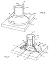
- FIGS. 8-10 illustrate one arrangement, wherein components common with those previously shown and described in FIGS. 1-7 are identified by common reference numerals increased by 100.
- a modified sealant mold 116 is provided for applying a curable sealant material 114 about the attachment interface between the dome 118 of a domed nutplate unit 110 or the like secured onto a blind side of a substrate 112, such as the wall of an aircraft fuel tank or the like.
- the sealant mold 116 comprises an inner cap 122 having a size and shape for relatively close-fitting sliding relation within an upper cylindrical region 126 of an outer skirt 124, a lower end of which includes an outwardly and downwardly angled flared segment 128 terminating in an outer rim 130.
- the assembled components of the sealant mold 116 are pre-filled with a metered quantity of the selected sealant material 114 in the same manner are previously shown and described with respect to FIG. 2 .
- the sealant mold 116 with the metered quantity of the curable sealant material 114 is then fitted onto the dome 118 of the nutplate unit 110 ( FIG. 9 ), with the inner cap 122 having a size and shape for relatively close slide-fit reception over the dome 118.
- a lower end 140 of the inner cap 122 is landed upon a radially enlarged shoulder 142 at the lower end of the dome 118.
- the outer skirt 124 is then displaced downwardly in a direction toward the substrate 112 to extrude the sealant material 114 into a relatively thin and substantially uniform layer for securely interconnecting the dome 118 with the substrate 112, all in the manner previously shown and described herein.
- FIGS. 8-10 The difference between the arrangement of FIGS. 8-10 versus the arrangement of FIGS. 1-7 relates primarily to a reshaped upper end 144 of the inner cap 122. More particularly, instead of the fully open cylindrical shape depicted in FIGS. 1-7 , the arrangement of FIGS. 8-10 shows a partially closed upper end 144 with a small post 145 formed therein. With this configuration, after a suitable cure time for the sealant material 114, the entire sealant mold 116 is removed quickly and easily from the cured sealant material as by coupling the upper port 145 to a suitable source 148 of pressurized air or the like.
- sealant mold components By constructing the sealant mold components from a suitable plastic or plastic-based material that does not permanently adhere to the cured sealant material 114, such brief application of pressurized air or other selected compressed gas through the port 145 and into the upper region of the inner cap 122 is effective to release the entire sealant mold 116 from the cured sealant material 114, as viewed in FIG. 10 .
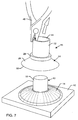
- FIGS. 11-12 A further arrangement is shown in FIGS. 11-12 , wherein components corresponding in structure and function with those previously shown and described in FIGS. 1-7 are identified by common reference numerals increased by 200.
- the sealant mold 216 is constructed with a one-piece or unitary construction to include the inner cap 222 in combination with an outwardly flared lower skirt 224.
- the inner cap 222 defines a lower end 240 for seating upon a radially enlarged shoulder (not shown) at the lower end of domed nutplate unit (also not shown).
- the cylindrical interior of the inner cap 222 is sized and shaped for relatively close slide-fit reception over the dome (not shown) of a domed nutplate unit.
- An upper end 244 of the inner cap 222 is shown to be fully open (consistent with FIGS. 1-7 ), although persons skilled in the art will recognize and appreciate that the upper end 244 can be partially closed and include a small port formed therein per FIGS. 8-10 , if desired.
- the outer skirt 224 of the modified sealant mold 216 includes the outwardly flared lower region 228 extending outwardly from the inner cap 222.
- the outwardly flared lower region initially defines the annular trough or gap 232 for receiving a metered quantity of the selected sealant material 214 ( FIG. 11 ).
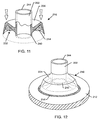
- the inner cap 222 of the sealant mold 216 is initially fitted onto a domed nutplate unit mounted previously onto a selected substrate 212 ( FIG. 12 ).
- the lower end 240 of the inner cap 222 is seated upon the dome shoulder (as previously shown and described), followed in turn by displacement of the outer skirt flared lower region 228 downwardly or toward the adjacent substrate 212 ( FIG. 12 ).
- the sealant mold 216 is quickly and easily removed, as previously described, from the cured sealant material.
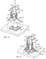
- FIGS. 13-15 show a sealant mold fixture embodying the invention, wherein components corresponding in structure and function with those previously shown and described in FIGS. 1-7 are identified by common reference numerals increased by 300.
- a modified sealant mold 316 is provided for applying a curable sealant material 314 about the attachment interface between a dome 318 of a domed nutplate unit 310 or the like secured onto a blind side of a substrate 312, such as the wall of an aircraft fuel tank or the like.
- the sealant mold 316 comprises an inner cap 322 defining an inboard wall of an upper and generally cylindrical chamber 350, the outer wall of which is defined by a generally cylindrical outer skirt 324.
- a lower end of the outer skirt 324 blends smoothly with an outwardly and downwardly angled flared Segment 328 terminating in an outer rim 330.
- the inner cap 322 of the sealant mold 316 defines an internal wall or boundary of the generally cylindrical cavity or chamber 350 defined by the sealant mold 316.
- the outer wall or boundary of this chamber 350 is defined by an upstanding outer skirt 324 on the sealant mold 316, and a lower wall or boundary is defined by a short annular wall 354 which interconnects the inner cap 322 with the outer skirt 324 and has an array or plurality of small passages 356 formed therein.
- This otherwise open-topped chamber 350 is prefilled with a metered quantity of the selected curable sealant material 314, followed by closing of the upper region of the chamber 350 with an annular-shaped plunger 358 or the like which fits slidably with relatively close tolerance therein.
- the assembled components of the sealant mold 316 are then positioned over the dome 318 of a nutplate unit 310 or the like, as viewed in FIG. 13 .
- the sealant material 314 is disposed entirely within the sealant mold chamber 350.
- the sealant mold 316 is then pressed downwardly over the underlying dome 318 until the outer rim 330 of the downwardly angled flared segment 328 seats substantially upon the blind side of the substrate 312 in circumscribing relation with the attachment interface or bead 320 of the nutplate unit 310 or the like.
- the plunger 358 is slidably depressed in a direction toward the substrate 312 to extrude the sealant material 314 from the chamber 350 and through the array of passages 356 into a relatively thin and substantially uniform layer for securely interconnecting the dome 318 with the substrate 312, all in the manner previously shown and described herein.
- FIGS. 13-15 again shows a partially closed upper end 344 with a small port 345 formed therein.
- sealant mold components By constructing the sealant mold components from a suitable plastic or plastic-based material that does not permanently adhere to the cured sealant material 314, such brief application of pressurized air through the port 345 and into the upper region of the inner cap 322 is effective to release the entire sealant mold 316 from the cured sealant material 314, as viewed in FIG. 15 .
Landscapes
- Engineering & Computer Science (AREA)
- Mechanical Engineering (AREA)
- Gasket Seals (AREA)
- Lining Or Joining Of Plastics Or The Like (AREA)
- Casting Or Compression Moulding Of Plastics Or The Like (AREA)
- Casings For Electric Apparatus (AREA)
Applications Claiming Priority (3)
| Application Number | Priority Date | Filing Date | Title |
|---|---|---|---|
| US201161447557P | 2011-02-28 | 2011-02-28 | |
| US13/406,453 US8616868B2 (en) | 2011-02-28 | 2012-02-27 | Sealant mold fixture for a domed cap |
| PCT/US2012/027005 WO2012161845A1 (en) | 2011-02-27 | 2012-02-28 | Sealant mold fixture for a domed cap |
Publications (3)
| Publication Number | Publication Date |
|---|---|
| EP2679020A1 EP2679020A1 (en) | 2014-01-01 |
| EP2679020A4 EP2679020A4 (en) | 2014-06-18 |
| EP2679020B1 true EP2679020B1 (en) | 2016-02-24 |
Family
ID=46718427
Family Applications (1)
| Application Number | Title | Priority Date | Filing Date |
|---|---|---|---|
| EP12790036.3A Active EP2679020B1 (en) | 2011-02-28 | 2012-02-28 | Sealant mold fixture for a domed cap |
Country Status (6)
Families Citing this family (34)
| Publication number | Priority date | Publication date | Assignee | Title |
|---|---|---|---|---|
| DE102010032279B4 (de) * | 2010-07-26 | 2012-09-06 | Kautex Textron Gmbh & Co. Kg | Verfahren zur Nietbefestigung eines Zubehörteils |
| MX347916B (es) * | 2012-03-08 | 2017-05-17 | Jurblami S L | Molde de campanilla para encapsulados con sellante moldeable. |
| JP5989892B2 (ja) | 2012-04-11 | 2016-09-07 | ピーアールシー−デソト インターナショナル,インコーポレイティド | ナットプレートの封止キャップ |
| US9266140B2 (en) * | 2012-11-21 | 2016-02-23 | Lockheed Martin Corporation | Annular adhesive bead application |
| JP6270317B2 (ja) * | 2013-01-29 | 2018-01-31 | 三菱航空機株式会社 | 耐雷ファスナのシーラント層成形用治具、耐雷ファスナのシーラント層成形方法、耐雷ファスナ、航空機の翼、耐雷ファスナの成形方法および航空機の翼の製造方法 |
| JP6162964B2 (ja) * | 2013-01-29 | 2017-07-12 | 三菱航空機株式会社 | 耐雷ファスナのシーラント層成形用治具、耐雷ファスナのシーラント層成形方法 |
| US9259865B2 (en) * | 2013-03-17 | 2016-02-16 | The Boeing Company | Seal molding system and method |
| BR112015026815A2 (pt) * | 2013-04-22 | 2017-07-25 | Prc Desoto Int Inc | arranjo de tampa selante, método para fabricar um arranjo de tampa selante, método para selar um fixador e fixador selado |
| GB2516835B (en) * | 2013-07-31 | 2015-11-04 | Airbus Operations Ltd | Cap to accommodate washers |
| CN105473445B (zh) * | 2013-08-21 | 2017-10-03 | 空中客车营运有限公司 | 具有注入的密封剂的帽 |
| US9849637B2 (en) * | 2013-10-22 | 2017-12-26 | The Boeing Company | Self-centering sealant applicator |
| US9308702B2 (en) | 2014-02-25 | 2016-04-12 | The Boeing Company | Method and apparatus for making preformed seals |
| GB2535518A (en) * | 2015-02-20 | 2016-08-24 | Airbus Operations Ltd | Cap with injected sealant |
| US9968962B2 (en) | 2015-03-19 | 2018-05-15 | The Boeing Company | Material applicator comprising a surface interface guide forming a continuous ring shaped flow channel with an unobstructive guding assembly therein |
| US10737423B2 (en) | 2015-08-28 | 2020-08-11 | The Boeing Company | Systems and methods for sealant injection molding |
| CN118833518A (zh) | 2016-07-26 | 2024-10-25 | 凯密特尔有限责任公司 | 用于填充密封盖的方法和装置 |
| US10655667B2 (en) | 2017-09-28 | 2020-05-19 | The Boeing Company | Rapid installation thermoplastic EME protection cap |
| US10458455B2 (en) * | 2017-12-22 | 2019-10-29 | The Boeing Company | Systems and methods for making and using a fitted cap for applying a shaped sealant shroud to a portion of a fastener |
| US10962043B2 (en) | 2018-04-24 | 2021-03-30 | The Boeing Company | Anchoring nut for an EME protection cap system |
| US10920818B2 (en) | 2018-04-27 | 2021-02-16 | The Boeing Company | Anchoring washer for an EME protection cap system |
| US10948004B2 (en) | 2018-07-26 | 2021-03-16 | The Boeing Company | Anchoring bolt head for an EME protection cap system |
| US11045985B2 (en) | 2018-08-02 | 2021-06-29 | The Boeing Company | Self-holding and self-extracting seal molding system and method |
| US11078947B2 (en) | 2018-09-11 | 2021-08-03 | The Boeing Company | Combustion quenching fastener caps with holes |
| US11022164B2 (en) * | 2018-09-11 | 2021-06-01 | The Boeing Company | Double shell fastener caps |
| US11248647B2 (en) | 2018-11-09 | 2022-02-15 | The Boeing Company | EME cap for preventing uncured sealant squeeze out |
| US10989244B2 (en) * | 2018-11-20 | 2021-04-27 | The Boeing Company | EME protection cap system with push sealant extrusion mechanism |
| GB2579229A (en) | 2018-11-26 | 2020-06-17 | Airbus Operations Ltd | Spark containment cap |
| US10982704B2 (en) | 2019-01-03 | 2021-04-20 | The Boeing Company | EME protection cap system with screw sealant mechanism |
| US11819870B2 (en) | 2019-03-01 | 2023-11-21 | William Harrison | System and method for efficient and ergonomic waterproofing of joints and fasteners |
| US11236777B2 (en) | 2019-05-06 | 2022-02-01 | The Boeing Company | Friction fit electromagnetic effect protection cap system |
| US11788573B2 (en) | 2019-05-23 | 2023-10-17 | The Boeing Company | Multi-component melt electromagnetic effect protection cap system |
| US11754111B2 (en) | 2020-03-16 | 2023-09-12 | The Boeing Company | Compression fit EME protection seal cap |
| CN113399199B (zh) * | 2021-06-23 | 2022-10-25 | 成都飞机工业(集团)有限责任公司 | 一种螺母罩封系统及方法 |
| CN115654133A (zh) * | 2022-09-23 | 2023-01-31 | 中航通飞华南飞机工业有限公司 | 一种航空同质密封帽、成型模具及制造工艺方法 |
Family Cites Families (13)
| Publication number | Priority date | Publication date | Assignee | Title |
|---|---|---|---|---|
| GB1583143A (en) * | 1976-05-18 | 1981-01-21 | Normalair Garrett Ltd | Air cycle air conditioning systems |
| US4822656A (en) * | 1985-09-04 | 1989-04-18 | Physical Systems, Inc. | Fixture for securing an adhesive attachment to a substrate |
| US5013791A (en) | 1987-12-30 | 1991-05-07 | Ppg Industries, Inc. | Beta-hydroxyalkylamide cured acid polymer/polyepoxide powder coating |
| US5304747A (en) | 1993-02-12 | 1994-04-19 | Hale Ii Richard L | Speaker with motor-controlled internal baffle |
| US5593120A (en) * | 1994-11-21 | 1997-01-14 | Minnesota Mining And Manufacturing Company | Quick-mounting fastening assembly |
| US6439199B2 (en) * | 2000-04-20 | 2002-08-27 | Bosch Rexroth Corporation | Pilot operated throttling valve for constant flow pump |
| US6334298B1 (en) * | 2000-07-14 | 2002-01-01 | General Electric Company | Gas turbine combustor having dome-to-liner joint |
| US7575208B2 (en) * | 2003-10-27 | 2009-08-18 | Yung-Huei Lan | Holding device with a securing sheet for mounting onto a wall |
| CN1283572C (zh) * | 2001-07-11 | 2006-11-08 | 松下电器产业株式会社 | 模、板、吸附器、成型用金属模具、拆卸组装装置、拆卸组装方法、及透镜取出方法 |
| US8292253B2 (en) * | 2003-04-19 | 2012-10-23 | Eli Zhadanov | Device for supporting bathroom accessories and the like |
| US20070141289A1 (en) * | 2005-12-19 | 2007-06-21 | Physical Systems, Inc. | Peel ply masking device for an adhesive bonded attachment |
| US20090057510A1 (en) * | 2007-08-28 | 2009-03-05 | John Orban | Suction cup |
| US7900655B2 (en) * | 2008-07-18 | 2011-03-08 | Tdw Delaware, Inc. | Composite load transferring technique |
-
2012
- 2012-02-27 US US13/406,453 patent/US8616868B2/en active Active
- 2012-02-28 WO PCT/US2012/027005 patent/WO2012161845A1/en active Application Filing
- 2012-02-28 JP JP2013555641A patent/JP5897610B2/ja active Active
- 2012-02-28 BR BR112013021818-5A patent/BR112013021818B1/pt active IP Right Grant
- 2012-02-28 EP EP12790036.3A patent/EP2679020B1/en active Active
- 2012-02-28 CA CA2827995A patent/CA2827995C/en active Active
- 2012-02-28 BR BR112013021817-7A patent/BR112013021817B1/pt active IP Right Grant
Also Published As
| Publication number | Publication date |
|---|---|
| JP5897610B2 (ja) | 2016-03-30 |
| BR112013021817A2 (pt) | 2016-10-25 |
| WO2012161845A1 (en) | 2012-11-29 |
| BR112013021817B1 (pt) | 2021-02-02 |
| US20120217673A1 (en) | 2012-08-30 |
| BR112013021818A2 (pt) | 2016-10-25 |
| CA2827995A1 (en) | 2012-11-29 |
| BR112013021818B1 (pt) | 2020-12-08 |
| EP2679020A4 (en) | 2014-06-18 |
| US8616868B2 (en) | 2013-12-31 |
| JP2014510883A (ja) | 2014-05-01 |
| CA2827995C (en) | 2016-04-12 |
| EP2679020A1 (en) | 2014-01-01 |
Similar Documents
| Publication | Publication Date | Title |
|---|---|---|
| EP2679020B1 (en) | Sealant mold fixture for a domed cap | |
| US8602764B2 (en) | Sealant mold fixture for a dome element | |
| AU2016204078B2 (en) | Sealing system for fasteners | |
| US8388293B2 (en) | Insulated and sealed cap for a fastener component | |
| EP3078867B1 (en) | Systems and methods for use in covering a portion of a fastener protruding from a surface | |
| KR101961490B1 (ko) | 일체로 보강되고 재사용가능한 진공백과 이를 제조하는 방법 | |
| EP0181483A1 (en) | Method and apparatus for applying a precision amount of sealant to exposed fasteners | |
| WO2011055524A1 (ja) | 複合材料構造物製造用治具 | |
| EP3369546B1 (en) | Seal molding system | |
| WO2014201188A1 (en) | Sealant cap | |
| US20230183934A1 (en) | Manhole inserts | |
| US20160010322A1 (en) | Cluster cap sealing mechanism and method | |
| US20140352225A1 (en) | Motor vehicle seal | |
| US10676930B2 (en) | Drain retrofit and method | |
| EP3339662A1 (en) | Cap for a fastener | |
| EP4442441A1 (en) | A method for in-situ manufacturing a protective liner on an elongated structural part of an aircraft | |
| US20140091528A1 (en) | Sealed assemblies and methods of unsealing same | |
| ES2566367T3 (es) | Fijación de molde de sellado para una tapa en forma de cúpula | |
| US20240227247A9 (en) | In-mold sealing system to assist with vacuum assisted resin transfer molding | |
| WO2018169845A1 (en) | Dripless adapter for a fuel nozzle | |
| CN114571833A (zh) | 在构件的待保护的表面上安置防腐蚀层的方法 |
Legal Events
| Date | Code | Title | Description |
|---|---|---|---|
| PUAI | Public reference made under article 153(3) epc to a published international application that has entered the european phase |
Free format text: ORIGINAL CODE: 0009012 |
|
| 17P | Request for examination filed |
Effective date: 20130820 |
|
| AK | Designated contracting states |
Kind code of ref document: A1 Designated state(s): AL AT BE BG CH CY CZ DE DK EE ES FI FR GB GR HR HU IE IS IT LI LT LU LV MC MK MT NL NO PL PT RO RS SE SI SK SM TR |
|
| DAX | Request for extension of the european patent (deleted) | ||
| A4 | Supplementary search report drawn up and despatched |
Effective date: 20140515 |
|
| RIC1 | Information provided on ipc code assigned before grant |
Ipc: H04R 1/28 20060101AFI20140509BHEP Ipc: H05K 5/00 20060101ALI20140509BHEP |
|
| 17Q | First examination report despatched |
Effective date: 20150522 |
|
| GRAP | Despatch of communication of intention to grant a patent |
Free format text: ORIGINAL CODE: EPIDOSNIGR1 |
|
| INTG | Intention to grant announced |
Effective date: 20150925 |
|
| GRAS | Grant fee paid |
Free format text: ORIGINAL CODE: EPIDOSNIGR3 |
|
| GRAA | (expected) grant |
Free format text: ORIGINAL CODE: 0009210 |
|
| REG | Reference to a national code |
Ref country code: FR Ref legal event code: PLFP Year of fee payment: 5 |
|
| AK | Designated contracting states |
Kind code of ref document: B1 Designated state(s): AL AT BE BG CH CY CZ DE DK EE ES FI FR GB GR HR HU IE IS IT LI LT LU LV MC MK MT NL NO PL PT RO RS SE SI SK SM TR |
|
| REG | Reference to a national code |
Ref country code: GB Ref legal event code: FG4D |
|
| REG | Reference to a national code |
Ref country code: CH Ref legal event code: EP |
|
| REG | Reference to a national code |
Ref country code: AT Ref legal event code: REF Ref document number: 777271 Country of ref document: AT Kind code of ref document: T Effective date: 20160315 |
|
| REG | Reference to a national code |
Ref country code: IE Ref legal event code: FG4D |
|
| REG | Reference to a national code |
Ref country code: DE Ref legal event code: R096 Ref document number: 602012014997 Country of ref document: DE |
|
| REG | Reference to a national code |
Ref country code: ES Ref legal event code: FG2A Ref document number: 2566367 Country of ref document: ES Kind code of ref document: T3 Effective date: 20160412 |
|
| REG | Reference to a national code |
Ref country code: LT Ref legal event code: MG4D |
|
| REG | Reference to a national code |
Ref country code: NL Ref legal event code: MP Effective date: 20160224 |
|
| REG | Reference to a national code |
Ref country code: AT Ref legal event code: MK05 Ref document number: 777271 Country of ref document: AT Kind code of ref document: T Effective date: 20160224 |
|
| PG25 | Lapsed in a contracting state [announced via postgrant information from national office to epo] |
Ref country code: FI Free format text: LAPSE BECAUSE OF FAILURE TO SUBMIT A TRANSLATION OF THE DESCRIPTION OR TO PAY THE FEE WITHIN THE PRESCRIBED TIME-LIMIT Effective date: 20160224 Ref country code: HR Free format text: LAPSE BECAUSE OF FAILURE TO SUBMIT A TRANSLATION OF THE DESCRIPTION OR TO PAY THE FEE WITHIN THE PRESCRIBED TIME-LIMIT Effective date: 20160224 Ref country code: NO Free format text: LAPSE BECAUSE OF FAILURE TO SUBMIT A TRANSLATION OF THE DESCRIPTION OR TO PAY THE FEE WITHIN THE PRESCRIBED TIME-LIMIT Effective date: 20160524 Ref country code: GR Free format text: LAPSE BECAUSE OF FAILURE TO SUBMIT A TRANSLATION OF THE DESCRIPTION OR TO PAY THE FEE WITHIN THE PRESCRIBED TIME-LIMIT Effective date: 20160525 |
|
| PG25 | Lapsed in a contracting state [announced via postgrant information from national office to epo] |
Ref country code: LV Free format text: LAPSE BECAUSE OF FAILURE TO SUBMIT A TRANSLATION OF THE DESCRIPTION OR TO PAY THE FEE WITHIN THE PRESCRIBED TIME-LIMIT Effective date: 20160224 Ref country code: PT Free format text: LAPSE BECAUSE OF FAILURE TO SUBMIT A TRANSLATION OF THE DESCRIPTION OR TO PAY THE FEE WITHIN THE PRESCRIBED TIME-LIMIT Effective date: 20160624 Ref country code: SE Free format text: LAPSE BECAUSE OF FAILURE TO SUBMIT A TRANSLATION OF THE DESCRIPTION OR TO PAY THE FEE WITHIN THE PRESCRIBED TIME-LIMIT Effective date: 20160224 Ref country code: BE Free format text: LAPSE BECAUSE OF NON-PAYMENT OF DUE FEES Effective date: 20160229 Ref country code: AT Free format text: LAPSE BECAUSE OF FAILURE TO SUBMIT A TRANSLATION OF THE DESCRIPTION OR TO PAY THE FEE WITHIN THE PRESCRIBED TIME-LIMIT Effective date: 20160224 Ref country code: NL Free format text: LAPSE BECAUSE OF FAILURE TO SUBMIT A TRANSLATION OF THE DESCRIPTION OR TO PAY THE FEE WITHIN THE PRESCRIBED TIME-LIMIT Effective date: 20160224 Ref country code: RS Free format text: LAPSE BECAUSE OF FAILURE TO SUBMIT A TRANSLATION OF THE DESCRIPTION OR TO PAY THE FEE WITHIN THE PRESCRIBED TIME-LIMIT Effective date: 20160224 Ref country code: LT Free format text: LAPSE BECAUSE OF FAILURE TO SUBMIT A TRANSLATION OF THE DESCRIPTION OR TO PAY THE FEE WITHIN THE PRESCRIBED TIME-LIMIT Effective date: 20160224 Ref country code: PL Free format text: LAPSE BECAUSE OF FAILURE TO SUBMIT A TRANSLATION OF THE DESCRIPTION OR TO PAY THE FEE WITHIN THE PRESCRIBED TIME-LIMIT Effective date: 20160224 |
|
| REG | Reference to a national code |
Ref country code: CH Ref legal event code: PL |
|
| PG25 | Lapsed in a contracting state [announced via postgrant information from national office to epo] |
Ref country code: EE Free format text: LAPSE BECAUSE OF FAILURE TO SUBMIT A TRANSLATION OF THE DESCRIPTION OR TO PAY THE FEE WITHIN THE PRESCRIBED TIME-LIMIT Effective date: 20160224 Ref country code: LI Free format text: LAPSE BECAUSE OF NON-PAYMENT OF DUE FEES Effective date: 20160229 Ref country code: CH Free format text: LAPSE BECAUSE OF NON-PAYMENT OF DUE FEES Effective date: 20160229 Ref country code: DK Free format text: LAPSE BECAUSE OF FAILURE TO SUBMIT A TRANSLATION OF THE DESCRIPTION OR TO PAY THE FEE WITHIN THE PRESCRIBED TIME-LIMIT Effective date: 20160224 |
|
| REG | Reference to a national code |
Ref country code: DE Ref legal event code: R097 Ref document number: 602012014997 Country of ref document: DE |
|
| PG25 | Lapsed in a contracting state [announced via postgrant information from national office to epo] |
Ref country code: CZ Free format text: LAPSE BECAUSE OF FAILURE TO SUBMIT A TRANSLATION OF THE DESCRIPTION OR TO PAY THE FEE WITHIN THE PRESCRIBED TIME-LIMIT Effective date: 20160224 Ref country code: RO Free format text: LAPSE BECAUSE OF FAILURE TO SUBMIT A TRANSLATION OF THE DESCRIPTION OR TO PAY THE FEE WITHIN THE PRESCRIBED TIME-LIMIT Effective date: 20160224 Ref country code: SK Free format text: LAPSE BECAUSE OF FAILURE TO SUBMIT A TRANSLATION OF THE DESCRIPTION OR TO PAY THE FEE WITHIN THE PRESCRIBED TIME-LIMIT Effective date: 20160224 Ref country code: SM Free format text: LAPSE BECAUSE OF FAILURE TO SUBMIT A TRANSLATION OF THE DESCRIPTION OR TO PAY THE FEE WITHIN THE PRESCRIBED TIME-LIMIT Effective date: 20160224 |
|
| REG | Reference to a national code |
Ref country code: IE Ref legal event code: MM4A |
|
| PG25 | Lapsed in a contracting state [announced via postgrant information from national office to epo] |
Ref country code: BE Free format text: LAPSE BECAUSE OF FAILURE TO SUBMIT A TRANSLATION OF THE DESCRIPTION OR TO PAY THE FEE WITHIN THE PRESCRIBED TIME-LIMIT Effective date: 20160224 |
|
| PLBE | No opposition filed within time limit |
Free format text: ORIGINAL CODE: 0009261 |
|
| STAA | Information on the status of an ep patent application or granted ep patent |
Free format text: STATUS: NO OPPOSITION FILED WITHIN TIME LIMIT |
|
| PG25 | Lapsed in a contracting state [announced via postgrant information from national office to epo] |
Ref country code: IE Free format text: LAPSE BECAUSE OF NON-PAYMENT OF DUE FEES Effective date: 20160228 |
|
| 26N | No opposition filed |
Effective date: 20161125 |
|
| REG | Reference to a national code |
Ref country code: FR Ref legal event code: PLFP Year of fee payment: 6 |
|
| PG25 | Lapsed in a contracting state [announced via postgrant information from national office to epo] |
Ref country code: SI Free format text: LAPSE BECAUSE OF FAILURE TO SUBMIT A TRANSLATION OF THE DESCRIPTION OR TO PAY THE FEE WITHIN THE PRESCRIBED TIME-LIMIT Effective date: 20160224 Ref country code: BG Free format text: LAPSE BECAUSE OF FAILURE TO SUBMIT A TRANSLATION OF THE DESCRIPTION OR TO PAY THE FEE WITHIN THE PRESCRIBED TIME-LIMIT Effective date: 20160524 |
|
| PG25 | Lapsed in a contracting state [announced via postgrant information from national office to epo] |
Ref country code: MT Free format text: LAPSE BECAUSE OF FAILURE TO SUBMIT A TRANSLATION OF THE DESCRIPTION OR TO PAY THE FEE WITHIN THE PRESCRIBED TIME-LIMIT Effective date: 20160224 |
|
| REG | Reference to a national code |
Ref country code: FR Ref legal event code: PLFP Year of fee payment: 7 |
|
| PG25 | Lapsed in a contracting state [announced via postgrant information from national office to epo] |
Ref country code: HU Free format text: LAPSE BECAUSE OF FAILURE TO SUBMIT A TRANSLATION OF THE DESCRIPTION OR TO PAY THE FEE WITHIN THE PRESCRIBED TIME-LIMIT; INVALID AB INITIO Effective date: 20120228 Ref country code: CY Free format text: LAPSE BECAUSE OF FAILURE TO SUBMIT A TRANSLATION OF THE DESCRIPTION OR TO PAY THE FEE WITHIN THE PRESCRIBED TIME-LIMIT Effective date: 20160224 |
|
| PG25 | Lapsed in a contracting state [announced via postgrant information from national office to epo] |
Ref country code: MC Free format text: LAPSE BECAUSE OF FAILURE TO SUBMIT A TRANSLATION OF THE DESCRIPTION OR TO PAY THE FEE WITHIN THE PRESCRIBED TIME-LIMIT Effective date: 20160224 Ref country code: IS Free format text: LAPSE BECAUSE OF FAILURE TO SUBMIT A TRANSLATION OF THE DESCRIPTION OR TO PAY THE FEE WITHIN THE PRESCRIBED TIME-LIMIT Effective date: 20160224 Ref country code: MT Free format text: LAPSE BECAUSE OF FAILURE TO SUBMIT A TRANSLATION OF THE DESCRIPTION OR TO PAY THE FEE WITHIN THE PRESCRIBED TIME-LIMIT Effective date: 20160229 Ref country code: LU Free format text: LAPSE BECAUSE OF NON-PAYMENT OF DUE FEES Effective date: 20160228 Ref country code: TR Free format text: LAPSE BECAUSE OF FAILURE TO SUBMIT A TRANSLATION OF THE DESCRIPTION OR TO PAY THE FEE WITHIN THE PRESCRIBED TIME-LIMIT Effective date: 20160224 Ref country code: MK Free format text: LAPSE BECAUSE OF FAILURE TO SUBMIT A TRANSLATION OF THE DESCRIPTION OR TO PAY THE FEE WITHIN THE PRESCRIBED TIME-LIMIT Effective date: 20160224 |
|
| PG25 | Lapsed in a contracting state [announced via postgrant information from national office to epo] |
Ref country code: AL Free format text: LAPSE BECAUSE OF FAILURE TO SUBMIT A TRANSLATION OF THE DESCRIPTION OR TO PAY THE FEE WITHIN THE PRESCRIBED TIME-LIMIT Effective date: 20160224 |
|
| REG | Reference to a national code |
Ref country code: DE Ref legal event code: R082 Ref document number: 602012014997 Country of ref document: DE Representative=s name: MEISSNER BOLTE PATENTANWAELTE RECHTSANWAELTE P, DE |
|
| PGFP | Annual fee paid to national office [announced via postgrant information from national office to epo] |
Ref country code: DE Payment date: 20250227 Year of fee payment: 14 |
|
| PGFP | Annual fee paid to national office [announced via postgrant information from national office to epo] |
Ref country code: ES Payment date: 20250303 Year of fee payment: 14 |
|
| PGFP | Annual fee paid to national office [announced via postgrant information from national office to epo] |
Ref country code: FR Payment date: 20250225 Year of fee payment: 14 |
|
| PGFP | Annual fee paid to national office [announced via postgrant information from national office to epo] |
Ref country code: IT Payment date: 20250220 Year of fee payment: 14 Ref country code: GB Payment date: 20250227 Year of fee payment: 14 |