EP2678628B1 - Wärmetauscher mit einer laminarflussvorrichtung - Google Patents
Wärmetauscher mit einer laminarflussvorrichtung Download PDFInfo
- Publication number
- EP2678628B1 EP2678628B1 EP12748150.5A EP12748150A EP2678628B1 EP 2678628 B1 EP2678628 B1 EP 2678628B1 EP 12748150 A EP12748150 A EP 12748150A EP 2678628 B1 EP2678628 B1 EP 2678628B1
- Authority
- EP
- European Patent Office
- Prior art keywords
- cooling
- heat exchanger
- blood
- housing
- exchanger
- Prior art date
- Legal status (The legal status is an assumption and is not a legal conclusion. Google has not performed a legal analysis and makes no representation as to the accuracy of the status listed.)
- Not-in-force
Links
- 238000010438 heat treatment Methods 0.000 claims description 74
- 238000001816 cooling Methods 0.000 claims description 73
- 239000007788 liquid Substances 0.000 claims description 59
- 239000008280 blood Substances 0.000 claims description 53
- 210000004369 blood Anatomy 0.000 claims description 53
- 238000005192 partition Methods 0.000 claims description 39
- 230000017531 blood circulation Effects 0.000 claims description 13
- 239000004033 plastic Substances 0.000 claims description 8
- 229920003023 plastic Polymers 0.000 claims description 8
- 238000005094 computer simulation Methods 0.000 description 10
- XLYOFNOQVPJJNP-UHFFFAOYSA-N water Substances O XLYOFNOQVPJJNP-UHFFFAOYSA-N 0.000 description 10
- 239000000463 material Substances 0.000 description 9
- 230000000694 effects Effects 0.000 description 8
- 239000000110 cooling liquid Substances 0.000 description 7
- 238000010276 construction Methods 0.000 description 6
- 239000012153 distilled water Substances 0.000 description 6
- 230000023555 blood coagulation Effects 0.000 description 5
- 238000002474 experimental method Methods 0.000 description 5
- 238000004519 manufacturing process Methods 0.000 description 5
- 230000003247 decreasing effect Effects 0.000 description 4
- 230000009467 reduction Effects 0.000 description 4
- 230000015271 coagulation Effects 0.000 description 3
- 238000005345 coagulation Methods 0.000 description 3
- 239000003814 drug Substances 0.000 description 3
- 230000006872 improvement Effects 0.000 description 3
- 230000008901 benefit Effects 0.000 description 2
- 230000004087 circulation Effects 0.000 description 2
- 230000001419 dependent effect Effects 0.000 description 2
- 238000000502 dialysis Methods 0.000 description 2
- 238000002955 isolation Methods 0.000 description 2
- 230000007246 mechanism Effects 0.000 description 2
- 238000000034 method Methods 0.000 description 2
- 230000008569 process Effects 0.000 description 2
- 238000007789 sealing Methods 0.000 description 2
- 238000012795 verification Methods 0.000 description 2
- 239000004925 Acrylic resin Substances 0.000 description 1
- HTTJABKRGRZYRN-UHFFFAOYSA-N Heparin Chemical compound OC1C(NC(=O)C)C(O)OC(COS(O)(=O)=O)C1OC1C(OS(O)(=O)=O)C(O)C(OC2C(C(OS(O)(=O)=O)C(OC3C(C(O)C(O)C(O3)C(O)=O)OS(O)(=O)=O)C(CO)O2)NS(O)(=O)=O)C(C(O)=O)O1 HTTJABKRGRZYRN-UHFFFAOYSA-N 0.000 description 1
- 239000004698 Polyethylene Substances 0.000 description 1
- 239000000654 additive Substances 0.000 description 1
- 238000004026 adhesive bonding Methods 0.000 description 1
- 230000004075 alteration Effects 0.000 description 1
- 230000010100 anticoagulation Effects 0.000 description 1
- 230000005540 biological transmission Effects 0.000 description 1
- 230000008859 change Effects 0.000 description 1
- 239000004020 conductor Substances 0.000 description 1
- 239000002826 coolant Substances 0.000 description 1
- 238000009826 distribution Methods 0.000 description 1
- 238000005516 engineering process Methods 0.000 description 1
- 230000035876 healing Effects 0.000 description 1
- 229960002897 heparin Drugs 0.000 description 1
- 229920000669 heparin Polymers 0.000 description 1
- 230000001788 irregular Effects 0.000 description 1
- 208000017169 kidney disease Diseases 0.000 description 1
- 230000007774 longterm Effects 0.000 description 1
- 239000002184 metal Substances 0.000 description 1
- 238000002156 mixing Methods 0.000 description 1
- 238000012803 optimization experiment Methods 0.000 description 1
- 230000035515 penetration Effects 0.000 description 1
- 238000005293 physical law Methods 0.000 description 1
- 239000002504 physiological saline solution Substances 0.000 description 1
- 229920003229 poly(methyl methacrylate) Polymers 0.000 description 1
- 239000004926 polymethyl methacrylate Substances 0.000 description 1
- 239000004810 polytetrafluoroethylene Substances 0.000 description 1
- 229920001343 polytetrafluoroethylene Polymers 0.000 description 1
- 239000004814 polyurethane Substances 0.000 description 1
- 229920000915 polyvinyl chloride Polymers 0.000 description 1
- 239000004800 polyvinyl chloride Substances 0.000 description 1
- 230000020971 positive regulation of blood coagulation Effects 0.000 description 1
- 238000012545 processing Methods 0.000 description 1
- 238000011160 research Methods 0.000 description 1
- 238000007711 solidification Methods 0.000 description 1
- 230000008023 solidification Effects 0.000 description 1
- 239000000243 solution Substances 0.000 description 1
- -1 steam Substances 0.000 description 1
- 239000000126 substance Substances 0.000 description 1
- 229920002994 synthetic fiber Polymers 0.000 description 1
- 238000012360 testing method Methods 0.000 description 1
Images


Classifications
-
- F—MECHANICAL ENGINEERING; LIGHTING; HEATING; WEAPONS; BLASTING
- F28—HEAT EXCHANGE IN GENERAL
- F28F—DETAILS OF HEAT-EXCHANGE AND HEAT-TRANSFER APPARATUS, OF GENERAL APPLICATION
- F28F1/00—Tubular elements; Assemblies of tubular elements
-
- F—MECHANICAL ENGINEERING; LIGHTING; HEATING; WEAPONS; BLASTING
- F28—HEAT EXCHANGE IN GENERAL
- F28D—HEAT-EXCHANGE APPARATUS, NOT PROVIDED FOR IN ANOTHER SUBCLASS, IN WHICH THE HEAT-EXCHANGE MEDIA DO NOT COME INTO DIRECT CONTACT
- F28D7/00—Heat-exchange apparatus having stationary tubular conduit assemblies for both heat-exchange media, the media being in contact with different sides of a conduit wall
- F28D7/16—Heat-exchange apparatus having stationary tubular conduit assemblies for both heat-exchange media, the media being in contact with different sides of a conduit wall the conduits being arranged in parallel spaced relation
-
- F—MECHANICAL ENGINEERING; LIGHTING; HEATING; WEAPONS; BLASTING
- F28—HEAT EXCHANGE IN GENERAL
- F28F—DETAILS OF HEAT-EXCHANGE AND HEAT-TRANSFER APPARATUS, OF GENERAL APPLICATION
- F28F13/00—Arrangements for modifying heat-transfer, e.g. increasing, decreasing
- F28F13/06—Arrangements for modifying heat-transfer, e.g. increasing, decreasing by affecting the pattern of flow of the heat-exchange media
-
- F—MECHANICAL ENGINEERING; LIGHTING; HEATING; WEAPONS; BLASTING
- F28—HEAT EXCHANGE IN GENERAL
- F28F—DETAILS OF HEAT-EXCHANGE AND HEAT-TRANSFER APPARATUS, OF GENERAL APPLICATION
- F28F9/00—Casings; Header boxes; Auxiliary supports for elements; Auxiliary members within casings
- F28F9/22—Arrangements for directing heat-exchange media into successive compartments, e.g. arrangements of guide plates
-
- F—MECHANICAL ENGINEERING; LIGHTING; HEATING; WEAPONS; BLASTING
- F28—HEAT EXCHANGE IN GENERAL
- F28D—HEAT-EXCHANGE APPARATUS, NOT PROVIDED FOR IN ANOTHER SUBCLASS, IN WHICH THE HEAT-EXCHANGE MEDIA DO NOT COME INTO DIRECT CONTACT
- F28D21/00—Heat-exchange apparatus not covered by any of the groups F28D1/00 - F28D20/00
- F28D2021/0019—Other heat exchangers for particular applications; Heat exchange systems not otherwise provided for
- F28D2021/005—Other heat exchangers for particular applications; Heat exchange systems not otherwise provided for for medical applications
-
- F—MECHANICAL ENGINEERING; LIGHTING; HEATING; WEAPONS; BLASTING
- F28—HEAT EXCHANGE IN GENERAL
- F28F—DETAILS OF HEAT-EXCHANGE AND HEAT-TRANSFER APPARATUS, OF GENERAL APPLICATION
- F28F21/00—Constructions of heat-exchange apparatus characterised by the selection of particular materials
- F28F21/06—Constructions of heat-exchange apparatus characterised by the selection of particular materials of plastics material
- F28F21/062—Constructions of heat-exchange apparatus characterised by the selection of particular materials of plastics material the heat-exchange apparatus employing tubular conduits
Definitions
- the invention relates to a heat exchanger enabling efficient and uniform cooling and/or heating of blood.
- This exchanger is intended particularly for use in medicine.
- a heat exchanger suitable for blood according to the preamble of claim 1 is disclosed in US4177816 , where the tubes for leading blood are of metal and contain inserts (for example in the shape of a strip) for ensuring the laminar flow of blood.
- a tube heat exchanger made of plastics, suitable for medical use, i.e. for cooling/heating of blood, is disclosed in JP56059197 .
- the exchanger disclosed in JP2102661 tries to achieve a higher efficiency of heat exchange by leading the cooling liquid through metallic tubes inside the body of the exchanger and blood flows through the body of the exchanger.
- the inventors therefore designed a new heat exchanger containing a new element - laminarizer - which regulates the flow of the cooling/heating liquid so that the flow is uniform, which eliminates blind spots in the body of the exchanger and increases the cooling/heating effect of the heat exchanger.
- the invention relates to a heat exchanger for cooling or heating (for simplification referred to throughout the text as cooling/heating) of blood in external blood circulation.
- the heat exchanger according to the invention comprises an outer housing, in which a plurality of capillaries (tubes or pipes of a small diameter; the terms capillary, capillary tube, tube or pipe are used herein interchangeably).
- Capillaries are fixed inside the housing by means of partitions and they go through at least one, preferably two (optionally more) laminarizers.
- the housing serves to maintain the cooling/heating liquids in contact with capillaries, as well as as a supporting construction of the device, and also as a heat isolation of the cooling/heating liquid.
- a feeding opening (inlet) and draining opening (outlet) of the cooling/heating liquid In the perimeter of the housing are placed a feeding opening (inlet) and draining opening (outlet) of the cooling/heating liquid, and further the fixing elements for locking the inner parts, i.e. partitions and one or more laminarizers.
- the outer ends of the housing are on both sides provided with a finishing element the aim of which is to take in and take out the cooled/heated blood by means of the intake opening (input) and exit opening (output).
- the partitions serve to fix the capillaries and are placed near the ends of the housing and they are fastened by means of fixing elements.
- Such a fixing maintains all capillaries (namely if flexible tubes are used) in a tightened and parallel position with a precisely defined distance and distribution of individual capillaries over the whole length of their laying.
- At least one laminarizer preferably two laminarizers, are placed so that they lay in the space between the partitions fixing capillaries, in a suitably selected distance from the partitions to fix the capillary tubes, so that the space between the laminarizer and the partition were small, yet so that it enabled the inlet and outlet of the cooling/heating liquid.
- one or more laminarizers may be placed inside the housing, at regular or irregular distances.
- the laminarizer is tightly fixed to the housing by fixing elements, axially symmetrical to the partitions and capillaries, just as the partition, so it does not move and the axial symmetry of individual capillaries and the openings in the laminarizer is maintained.
- the laminarizer regulates the flow of the cooling/heating liquid so that a regular, substantially laminar flow occurs, eliminating the blind spots and increasing the cooling/heating effects of the heat exchanger.
- the exchanger according to the invention is constructed so that it meets the requirements for medical use, both from the material and functional points of view.
- the exchanger i.e. all components thereof, is made of plastics, either by one type, or by a combination of more types (e.g. PVC, PMMA, PTFE, PE, PUR, etc.), which on one hand are poor heat conducting materials, but on the other hand are routinely used thanks to their short-term, and in some cases even long-term, medical harmlessness namely in medicine, food industry, etc. Some of these materials are moreover easily processable and their price is low, which is important mainly from the commercial point of view, namely in case of exchangers for medical use, where single-use (i.e. disposable exchanger) is expected.
- the poor heat conductivity is to a certain extent advantageous, since only a low transmission of heat between the exchanger and surroundings thereof occurs.
- the connection of materials and individual parts is solved by pouring by the same or different type of plastics, by gluing, heat-sealing or compressing.
- the technologies of processing of plastics and plastic products suitable for manufacturing the heat exchanger according to the invention are commonly known to a person skilled in the art.
- the cooling/heating liquid is any non-aggressive liquid; distilled water is convenient, possibly with additives lowering the solidification point, which are not aggressive towards the materials used in the exchanger.
- the suitable coolant is physiological saline.
- the overall volume of the cooled/heated blood in the exchanger is minimised to volumes of tens of mililitres, which is advantageous in applications requiring minimum losses in volumes - e.g. extracorporeal blood circulation. This volume is the least in the preferred embodiment of heat exchanger in example 3 where, apart from other part improvements, the reduction of the residual volumes of the cooled/heated blood occurred, compared to the embodiment from example 2.
- the exchanger Due to the fact that the exchanger is intended primarily for medical use, it is constructed in order to reduce the risks arising with the blood circulation. Among the basic risks in the case is the risk of blood coagulation which might occur if it flowed slowly. It is therefore essential to ensure a sufficient speed of blood flow through the capillaries of the exchanger. However, at higher speeds, the time when blood is in contact with the inner walls of capillaries is reduced - to compensate for this phenomenon, it was necessary to maximise the area the blood is in contact with.
- the volume of flowing blood (which should be as small as possible), cross-section of capillaries, their length, hydrodynamic resistance (which is important in connection with further devices, such as dialysis monitor), the volume of cooling/heating liquid flowing around the capillaries and the overall volume of the exchanger.
- the exchanger according to the invention in the embodiments mentioned in examples represents a compromise between all the above mentioned requirements.
- a skilled person will understand that the particular dimensions and shapes of parts of the exchanger may be adjusted, without such an exchanger deviating from the concept of the heat exchanger according to the invention as described herein and as defined in the patent claims.
- the selected parameters of the exchanger ensure a very low hydrodynamic resistance (the exchanger increases the pressure of flowing blood only by units of kPa) and a risk-free speed of flowing blood (units of ml/s) while increasing the maximum possible temperature increase or reduction.
- a heat exchanger for cooling or heating blood in external blood circulation comprising elongated, substantially cylindrical, housing, a plurality of capillaries which are fastened inside the housing by means of partitions, so that they are substantially parallel with the longitudinal axis of the housing and are mutually placed in defined distances from each other, while the housing contains an inlet and an outlet of the cooling/heating liquid, and at each end a finishing element containing the input or output of the cooled/heated blood, characterised by the fact that it contains at least one laminarizer in the form of a partition inside the housing, with a plurality of openings, always one opening for each capillary, the diameter of the opening being bigger than the outer diameter of the capillary, and the laminarizer is placed so that capillaries go through the centre of the openings in the laminarizer, wherein the partitions are placed in the housing so that mounting side of the partition is oriented towards the space for cooling/heating liquid, at least one laminarizer and
- the heat exchanger according to the present invention contains two laminarizers.
- the heat exchanger according to the invention is preferably provided on the input and/or output of the cooled/heated blood with a temperature sensor.
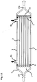
- Fig. 1.1 represents a reference heat exchanger (which substantially corresponds to the heat exchanger according to the state of the art), i.e. a heat exchanger without a laminarizer.
- the heat exchanger contains an elongated, substantially cylindrical, housing 1 , a plurality of capillaries 2 (which are for example tubes or pipes), which are fastened inside the housing 1 by means of partitions 5 , so that they are substantially parallel with the longitudinal axis of the housing 1 .
- capillaries 2 which are for example tubes or pipes
- the housing 1 serves to keep the cooling/heating liquid in contact with capillaries 2 , as well as as a supporting construction of the device, and also as a heat isolation of the cooling/heating liquid.
- a finishing element 9 is mounted on each outer end of the housing 1 , the aim of which is to take in or take out the cooled/heated blood by means of the input 12a or the output 12b.
- the inlet 4a of the cooling/heating liquid is placed on the opposite end of the housing 1 than the inlet 12a of the cooled/heated blood, since it is in principle a countercurrent heater exchanger (black arrows on Fig. 1.1 , 2.1 and 3.1 mark the flow direction of the cooling/heating liquid, white arrows mark the flow direction of the cooled/heated blood).
- the partitions 5 serve to fix the capillaries 2 , by pouring the space 11 by a suitable mounting material (e.g. acrylate resin, such as Spofakryl).
- the fixing partitions 5 are placed at both ends of the housing 1 are fastened by means of the fixing elements 8 .
- Such a locking keeps all capillaries 2 in a direct, non-deformed shape in exactly defined distances from one another, axially symmetrical with the partition and parallel to each other.
- the cooled/heated blood is led through the input 12a to capillaries 2 , which are oriented inside the housing 1 axially to the longitudinal axis of the housing. At the opposite end of the exchanger, the cooled/heated blood is led to the output 12b and leaves the heat exchanger.
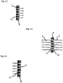
- the capillaries 2 are fastened in the partition 5 (detail on Fig. 1.2 ), which separates the space 3 for the cooling/heating liquid from the space 7 for the cooled/heated blood.
- the partition 5 contains the same number of opening as is the number of capillaries 2 of a substantially identical diameter (or rather adequately bigger so that capillaries 2 could be passed through the openings) as the outer diameter of capillaries 2 , capillaries 2 then being heat-sealed or glued (or fastened in any other suitable way, known to a skilled person) to the partition 5 , the connections being perfectly tight in order to avoid the undesirable mixing of the cooling/heating liquid and cooled/heated blood.
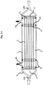
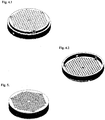
- the heat exchanger according to the invention (see embodiment on Fig. 2.1 a 3.1 ) is substantially similar to the embodiment according to example 1 ( Fig. 1.1 ). The essential difference is that it contains two laminarizers 6 (for detailed representation see Fig. 2.2 and Fig. 5 ), which effectively divide the flow of the cooling/heating liquid to all capillaries 2 , through which the cooled/heated blood flows, and regulate the flow of the cooling/heating liquid so that uniform and more effective heat exchange occurs on the outer surface of capillaries, and consequently also efficient cooling/heating of the cooled/heated blood.
- two laminarizers 6 for detailed representation see Fig. 2.2 and Fig. 5 , which effectively divide the flow of the cooling/heating liquid to all capillaries 2 , through which the cooled/heated blood flows, and regulate the flow of the cooling/heating liquid so that uniform and more effective heat exchange occurs on the outer surface of capillaries, and consequently also efficient cooling/heating of the cooled/heated blood.
- two laminarizers 6 are placed on both sides of the housing 1 of the exchanger in a suitable distance (approximately 1-2 cm from partitions 5 , i.e. approximately 3 cm from the ends of the housing 1 , the overall length of capillaries 2 being approximately 30 cm) from the fastening of capillaries 2 in the partition 5 .
- the laminarizers 6 are, similarly to partitions 5 , locked by means of fixing elements 8 to the housing 1 , so that they do not move.
- the outer diameter of the housing 1 is 70mm and the inner diameter of the housing is 62 mm.
- the size of the inner diameter is depending, among others, on the number of capillaries 2 in the exchanger.
- the exchanger contains capillaries having the length of 30 cm, having the inner diameter of 1 mm, outer diameter of 1.5 mm, the total number of capillaries being 200, the overall volume of the cooled blood in capillaries of the exchanger, including "dead spaces" is 65 ml. This arrangement ensures a very low hydrodynamic resistance; the exchanger increased the pressure of the flowing water only by 7 kPa. This preferred embodiment was selected based on previous optimization experiments and results of mathematical modeling.
- the aim of the laminarizer 6 is to ensure uniform flowing of the cooling/heating liquid inside the housing 1 , which, as was proven experimentally, significantly increases the cooling/heating effect of the exchanger, compared to the dimensionally identical exchanger without the laminarizer 6 (see example 1, Fig. 1.1 ).
- the laminarizer 6 is constructed substantially as a partition with the openings 10 for each capillary 2 .
- the laminarizer causes a uniform penetration of the cooling/heating liquid in openings 10 around capillaries 2 , while the whole exchanger is constructed so that capillaries 2 pass through the centre of the openings 10 in the laminarizer 6 .
- the size of the opening 10 is dependent, among others, on the diameter of the capillary, on the speed of flow of the cooling/heating liquid, on the inner diameter of the exchanger, and on the number and arrangement of capillaries.
- the diameter of the opening 10 is determined by physical laws known to a skilled person so that the cooling liquid creates laminar flow around individual capillaries (the Reynolds number for the given configuration is lower than 2000). The calculated value was then verified e.g. by means of a computer simulation and finally experimentally by verification of the efficiency of the exchanger in cooling/heating of the liquid (water, blood).
- the inlet 4a and the outlet 4b of the cooling/heating liquid in the perimeter of the housing 1 do not have to be placed in a mutually identical position with respect to the perimeter of the housing 1 (as shown e.g. on Fig. 2.1 ), they can be in any position to each other, for example advantageously in an "opposite" position (shifted by 180 ° on the perimeter of the housing 1 ).
- the exchanger according to the invention ensures cooling of the flowing blood, by 15 to 25 °C, depending on the chosen flow rate, characteristic for the given construction (e.g. 300 to 700 ml/min), at a temperature of the cooling temperature from 5 to 10 °C. With the decreasing flow rate of the cooled blood and the decreasing temperature of the cooling liquid, a higher temperature difference may be achieved.
- the exchanger is also intended for heating blood.
- the flowing blood may be heated by 15 to 25 °C.
- the cooled liquid (distilled water is used instead of blood in this test) at a temperature of 37 °C cooled down to 20 °C at the flow rate of 440 ml/min, at the temperature of the cooling liquid (distilled water) of 7 °C and the flow rate of the cooling liquid of 2 l/min.
- the exchanger with two laminarizers according to the invention led to the decrease of temperature of the cooled liquid from 37 °C to 15 °C, which is a significant difference.
- the heated liquid (distilled water) having the initial temperature of 20 °C was heated to 31 °C at the flow rate of 440 ml/min, temperature of the heating liquid of 44 °C and flow rate of the healing liquid of 2 l/min.
- the heated liquid (distilled water) was heated from 20 °C to 37 °C.
- the unmodified blood at the temperature of 36.6 °C was cooled down to 14.3 °C at the flow rate of 400 ml/min, at the temperature of the cooling liquid (distilled water) of 6.5 °C and the flow rate of the cooling liquid of 2 l/min.
- Another preferred embodiment of the heat exchanger is characterised by reduced residual volumes (namely the volume of the space 7 between the basic body of the housing 1 and the finishing element 9 ) and a simpler construction from the manufacturing point of view and is further provided by temperature sensors 16 at the input 12a and the output 12b of the exchanger.
- the construction was improved, firstly in the change of shape of the finishing element 9 (see Fig. 3.1 ), which led to the reduction of the space 7 , and thus to the reduction of the residual volume of the cooled/heated blood. Furthermore, the inner arrangement of the fixing partition 5 and the laminarizer 6 was improved. Moreover, the finishing element 9 contains an integrated temperature sensor 16, for direct measuring of temperature incoming and/or outgoing cooled/heated blood at the input 12a and the output 12b. By the suitable placing of the sensor 16 (Fig. 3.6) and by its minuscule size, its impact on the flow of the cooled/heated blood is minimised.
- the fixing partition 5 and the laminarizer 6 are in this embodiment tightly connected by three regularly placed distance pillars 15 (and thus form a complex called head).
- the fixing partition 5 has, contrary to the previous embodiment (example 2), oppositely localized space for fixing capillaries 2 by pouring the space 11 over by a suitable mounting material.
- This space 11 is placed here from the inner side (i.e. from the side intervening into the space 3 of the cooling/heating liquid) of the fixing partition 5 , as is apparent from Fig. 3.1 . and 3.2 ), in other words capillaries are poured by a sealing substance from the side of the cooling/heating liquid (i.e. in the space 3 and not in the space 7 , compare Fig. 2.1 . and 3.1 ). This prevents the contact of the mounting material with blood.
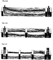
- Fig. 6.1 displays a computer simulation of the flow of the cooling/heating liquid in the reference heat exchanger without laminarizers 6 (example 1, Fig. 1.1 ). It is apparent from this model that the cooling/heating liquid does not flow uniformly; especially "blind" areas with minimum alteration of the cooling/heating liquid are formed.
- Fig. 6.2 exchanger according to Fig. 2.1
- 6.3 exchanger according to Fig. 3.1
- two laminarizers 6 in the exchanger according to the invention markedly regulate the flow of the cooling/heating liquid, and thus create a uniform flow, which eliminates blind spots and significantly improves the cooling/heating effect of the heat exchanger.
Landscapes
- Engineering & Computer Science (AREA)
- Physics & Mathematics (AREA)
- Thermal Sciences (AREA)
- Mechanical Engineering (AREA)
- General Engineering & Computer Science (AREA)
- External Artificial Organs (AREA)
- Heat-Exchange Devices With Radiators And Conduit Assemblies (AREA)
- Infusion, Injection, And Reservoir Apparatuses (AREA)
Claims (3)
- Wärmetauscher zum Kühlen oder Erwärmen von Blut in einem externen Blutkreislauf, umfassend ein langgestrecktes, im Wesentlichen zylindrisches Gehäuse (1), eine Vielzahl von Kapillaren (2), welche im Inneren des Gehäuses (1) durch Trennwände (5) befestigt sind, so dass sie im Wesentlichen parallel zu der Längsachse des Gehäuses (1) und in definierten Abständen zueinander angeordnet sind, wobei das Gehäuse (1) einen Einlass (4a) und einen Auslass (4b) für die Kühl-/Heizflüssigkeit und ein abschließendes Element (9) an jedem Ende umfasst, wobei das Element einen Einlass (12a) und einen Auslass (12b) für die Kühl-/Heizflüssigkeit umfasst, dadurch gekennzeichnet, dass der Wärmetauscher im Inneren des Gehäuses (1) mindestens einen Laminarisator (6) in Form einer Trennwand mit einer Vielzahl von Öffnungen (10) umfasst, jeweils eine Öffnung (10) für eine Kapillare (2), wobei der Durchmesser der Öffnung (10) größer ist als der äußere Durchmesser der Kapillare (2), und der Laminarisator (6) so angeordnet ist, dass die Kapillaren (2) durch die Mitte der Öffnungen (10) im Laminarisator (6) verlaufen, wobei die Trennwände (5) im Gehäuse so angeordnet sind, dass der Befestigungsbereich (11) der Trennwand (5) dem Bereich (3) für die Kühlung/Erwärmung der Flüssigkeit zugewandt ist, und mindestens ein Laminarisator (6) und die Trennwand (5) durch Abstandssäulen (15) verbunden sind, und der Wärmetauscher vollständig aus Plastik ist.
- Wärmetauscher gemäß Anspruch 1, dadurch gekennzeichnet, dass er zwei Laminarisatoren (6) umfasst.
- Wärmetauscher gemäß Anspruch 1 oder 2, dadurch gekennzeichnet, dass er einen Temperatursensor (16) am dem Einlass (12a) und/oder Auslass (12b) der gekühlten/erwärmten Flüssigkeit aufweist.
Applications Claiming Priority (2)
| Application Number | Priority Date | Filing Date | Title |
|---|---|---|---|
| CZ20110449A CZ303190B6 (cs) | 2011-07-22 | 2011-07-22 | Tepelný výmeník s laminarizérem |
| PCT/CZ2012/000067 WO2013013647A1 (en) | 2011-07-22 | 2012-07-20 | Heat exchanger with laminarizer |
Publications (2)
| Publication Number | Publication Date |
|---|---|
| EP2678628A1 EP2678628A1 (de) | 2014-01-01 |
| EP2678628B1 true EP2678628B1 (de) | 2017-02-01 |
Family
ID=46046382
Family Applications (1)
| Application Number | Title | Priority Date | Filing Date |
|---|---|---|---|
| EP12748150.5A Not-in-force EP2678628B1 (de) | 2011-07-22 | 2012-07-20 | Wärmetauscher mit einer laminarflussvorrichtung |
Country Status (5)
| Country | Link |
|---|---|
| US (1) | US9500415B2 (de) |
| EP (1) | EP2678628B1 (de) |
| CZ (1) | CZ303190B6 (de) |
| EA (1) | EA027362B1 (de) |
| WO (1) | WO2013013647A1 (de) |
Families Citing this family (4)
| Publication number | Priority date | Publication date | Assignee | Title |
|---|---|---|---|---|
| GB201319588D0 (en) * | 2013-11-06 | 2013-12-18 | Bae Systems Plc | Heat exchangers and the production thereof |
| RU2579788C1 (ru) * | 2014-12-30 | 2016-04-10 | Открытое акционерное общество "АКМЭ - инжиниринг" | Устройство дистанционирования трубок теплообменного аппарата (варианты) |
| CN106168451A (zh) * | 2016-08-27 | 2016-11-30 | 山东绿泉空调科技有限公司 | 高效毛细管套管换热器 |
| CN114110644B (zh) * | 2021-11-25 | 2022-08-02 | 淄博金通电力科技有限公司 | 一种受热面回转式空气预热器及其密封组件与制备方法 |
Citations (2)
| Publication number | Priority date | Publication date | Assignee | Title |
|---|---|---|---|---|
| US3566961A (en) * | 1967-09-06 | 1971-03-02 | Basf Ag | Tubular reactor for carrying out endothermic and exothermic reactions with forced circulation |
| US4188360A (en) * | 1978-09-08 | 1980-02-12 | Japan Medical Supply Co., Ltd. | Artificial lung with a built-in heat exchanger |
Family Cites Families (26)
| Publication number | Priority date | Publication date | Assignee | Title |
|---|---|---|---|---|
| US87479A (en) * | 1869-03-02 | Improvement in the manufacture of iron and steel | ||
| US827479A (en) * | 1905-12-26 | 1906-07-31 | Harry W Hand | Condenser. |
| US3848660A (en) * | 1970-08-17 | 1974-11-19 | Du Pont | Plastic heat exchange apparatus and a method for making |
| US3769162A (en) * | 1971-08-26 | 1973-10-30 | R Brumfield | Blood oxygenator and thermoregulator apparatus |
| US3934982A (en) * | 1972-06-01 | 1976-01-27 | Arp Leon J | Blood oxygenator |
| US3963071A (en) * | 1974-06-14 | 1976-06-15 | Evgeny Sergeevich Levin | Chell-and-tube heat exchanger for heating viscous fluids |
| US4162702A (en) * | 1977-03-29 | 1979-07-31 | Ab Svenska Maskinverken | Device for dividing the flow in a heat exchanger |
| US4204573A (en) * | 1977-05-09 | 1980-05-27 | Pvi Industries, Inc. | Heat exchanger with concentric flow tubes |
| US4177816A (en) * | 1978-03-27 | 1979-12-11 | Sci-Med Life Systems, Inc. | Heat exchanger for blood |
| US4342723A (en) * | 1978-11-24 | 1982-08-03 | Shin-Etsu Polymer Co., Ltd. | Gas-exchange sheet members |
| JPS5659197A (en) | 1979-10-19 | 1981-05-22 | Terumo Corp | Multitubular type heat exchanger and its preparation |
| JPS6057872B2 (ja) * | 1981-11-18 | 1985-12-17 | テルモ株式会社 | 熱交換器内蔵中空糸型人工肺 |
| CA1251109A (en) * | 1984-04-24 | 1989-03-14 | Tohru Takemura | Blood oxygenator using a hollow-fiber membrane |
| US5294397A (en) * | 1987-06-28 | 1994-03-15 | Terumo Kabushiki Kaisha | Heat exchanger for medical treatment |
| EP0524662B1 (de) * | 1987-06-28 | 1997-11-12 | Terumo Kabushiki Kaisha | Verfahren zur Herstellung eines medizinischen Wärmetauschers |
| CS269522B1 (cs) | 1988-01-03 | 1990-04-11 | Ludovit Kozolka | Trubkový výmenník tepla |
| JP2792049B2 (ja) | 1988-10-07 | 1998-08-27 | 大日本インキ化学工業株式会社 | 医療用の熱交換器 |
| JPH0614965B2 (ja) * | 1989-01-10 | 1994-03-02 | テルモ株式会社 | 人工肺 |
| JPH0347271A (ja) * | 1989-07-14 | 1991-02-28 | Terumo Corp | 液体処理器 |
| EP0452902A3 (en) * | 1990-04-18 | 1992-02-26 | Terumo Kabushiki Kaisha | Hollow fiber type liquid processing apparatus |
| JP2554016B2 (ja) * | 1994-02-22 | 1996-11-13 | 岩谷テクノコンストラクション株式会社 | 極低温医療装置 |
| US6458109B1 (en) * | 1998-08-07 | 2002-10-01 | Hill-Rom Services, Inc. | Wound treatment apparatus |
| US6206086B1 (en) * | 2000-02-21 | 2001-03-27 | R. P. Adams Co., Inc. | Multi-pass tube side heat exchanger with removable bundle |
| AR058207A1 (es) * | 2006-11-21 | 2008-01-23 | Consejo Nac Invest Cient Tec | Sistema pasivo de regulacion de caudal aplicable en intercambiadores de calor |
| CZ300266B6 (cs) * | 2008-01-22 | 2009-04-01 | Univerzita Karlova v Praze, Lékarská fakulta v Plzni | Zpusob snížení srážlivosti krve v okruhu prístroje pro náhradu funkce ledvin a zarízení k provádení tohoto zpusobu |
| US20100282451A1 (en) * | 2009-05-06 | 2010-11-11 | Singh Krishna P | Heat exchanger apparatus |
-
2011
- 2011-07-22 CZ CZ20110449A patent/CZ303190B6/cs not_active IP Right Cessation
-
2012
- 2012-07-20 WO PCT/CZ2012/000067 patent/WO2013013647A1/en not_active Ceased
- 2012-07-20 EP EP12748150.5A patent/EP2678628B1/de not_active Not-in-force
- 2012-07-20 EA EA201490325A patent/EA027362B1/ru not_active IP Right Cessation
- 2012-07-20 US US14/007,920 patent/US9500415B2/en not_active Expired - Fee Related
Patent Citations (2)
| Publication number | Priority date | Publication date | Assignee | Title |
|---|---|---|---|---|
| US3566961A (en) * | 1967-09-06 | 1971-03-02 | Basf Ag | Tubular reactor for carrying out endothermic and exothermic reactions with forced circulation |
| US4188360A (en) * | 1978-09-08 | 1980-02-12 | Japan Medical Supply Co., Ltd. | Artificial lung with a built-in heat exchanger |
Also Published As
| Publication number | Publication date |
|---|---|
| CZ2011449A3 (cs) | 2012-05-16 |
| US9500415B2 (en) | 2016-11-22 |
| WO2013013647A1 (en) | 2013-01-31 |
| EA201490325A1 (ru) | 2014-06-30 |
| CZ303190B6 (cs) | 2012-05-16 |
| EA027362B1 (ru) | 2017-07-31 |
| US20140020868A1 (en) | 2014-01-23 |
| EP2678628A1 (de) | 2014-01-01 |
Similar Documents
| Publication | Publication Date | Title |
|---|---|---|
| US10022482B2 (en) | Heat exchange device | |
| RU2014127153A (ru) | Терморегулируемые несущие поверхности для гибких настенных систем одноразового использования | |
| US9500415B2 (en) | Heat exchanger with laminarizer | |
| CN101374563A (zh) | 血液和生物液体加温器 | |
| RU2011106151A (ru) | Диспенсер для горячей и холодной воды | |
| RU2014112336A (ru) | Система трубопроводов для теплообменников | |
| US20110168368A1 (en) | Heat exchanger | |
| CN103743087B (zh) | 节能换热器 | |
| Choudhari et al. | Electroosmosis augmented MHD third-grade fluid with slip and variable properties: an application for blood flow in arteries | |
| AU2015339717A1 (en) | Heat exchanger with helical passageways | |
| Akbar et al. | Simulation of thermal and velocity slip on the peristaltic flow of a Johnson–Segalman fluid in an inclined asymmetric channel | |
| WO2015026630A1 (en) | Water delivery system for an evaporative cooler | |
| CZ22661U1 (cs) | Tepelný výměník s laminarizérem | |
| Yakar | Experimental analysis of conical baffles with rifts on heat transfer and pressure drop | |
| RU2017138471A (ru) | Канюльное устройство, аппарат искусственного дыхания | |
| CN100554863C (zh) | 干式冷槽 | |
| Sarkar et al. | Magnetohydrodynamic peristaltic flow of nanofluids in a vertical asymmetric channel filled with porous medium in presence of thermal radiation | |
| Murugesan et al. | The effect of mass flow rate on the enhanced heat transfer charactristics in a corrugated plate type heat exchanger | |
| CN103018430B (zh) | 一种串联血管灌流系统血管槽 | |
| CN210301870U (zh) | 一种适于循环管路温度调节的简易装置 | |
| CN208511600U (zh) | 血液透析用回输管 | |
| CN215337048U (zh) | 一种恒温式的水疗仪水箱机构 | |
| CN102889804A (zh) | U形管式换热器 | |
| CN208704496U (zh) | 一种新型热交换器 | |
| Eldabe et al. | Electro-osmosis and coupled stress effect on peristaltic power-law fluid flow with gold nanoparticles through a non-Darcy porous medium |
Legal Events
| Date | Code | Title | Description |
|---|---|---|---|
| PUAI | Public reference made under article 153(3) epc to a published international application that has entered the european phase |
Free format text: ORIGINAL CODE: 0009012 |
|
| 17P | Request for examination filed |
Effective date: 20130925 |
|
| AK | Designated contracting states |
Kind code of ref document: A1 Designated state(s): AL AT BE BG CH CY CZ DE DK EE ES FI FR GB GR HR HU IE IS IT LI LT LU LV MC MK MT NL NO PL PT RO RS SE SI SK SM TR |
|
| DAX | Request for extension of the european patent (deleted) | ||
| 17Q | First examination report despatched |
Effective date: 20141121 |
|
| GRAP | Despatch of communication of intention to grant a patent |
Free format text: ORIGINAL CODE: EPIDOSNIGR1 |
|
| INTG | Intention to grant announced |
Effective date: 20160829 |
|
| GRAS | Grant fee paid |
Free format text: ORIGINAL CODE: EPIDOSNIGR3 |
|
| GRAA | (expected) grant |
Free format text: ORIGINAL CODE: 0009210 |
|
| AK | Designated contracting states |
Kind code of ref document: B1 Designated state(s): AL AT BE BG CH CY CZ DE DK EE ES FI FR GB GR HR HU IE IS IT LI LT LU LV MC MK MT NL NO PL PT RO RS SE SI SK SM TR |
|
| REG | Reference to a national code |
Ref country code: GB Ref legal event code: FG4D |
|
| REG | Reference to a national code |
Ref country code: CH Ref legal event code: EP Ref country code: AT Ref legal event code: REF Ref document number: 865940 Country of ref document: AT Kind code of ref document: T Effective date: 20170215 |
|
| REG | Reference to a national code |
Ref country code: IE Ref legal event code: FG4D |
|
| REG | Reference to a national code |
Ref country code: DE Ref legal event code: R096 Ref document number: 602012028295 Country of ref document: DE |
|
| REG | Reference to a national code |
Ref country code: NL Ref legal event code: MP Effective date: 20170201 |
|
| REG | Reference to a national code |
Ref country code: LT Ref legal event code: MG4D |
|
| REG | Reference to a national code |
Ref country code: AT Ref legal event code: MK05 Ref document number: 865940 Country of ref document: AT Kind code of ref document: T Effective date: 20170201 |
|
| REG | Reference to a national code |
Ref country code: FR Ref legal event code: PLFP Year of fee payment: 6 |
|
| RAP2 | Party data changed (patent owner data changed or rights of a patent transferred) |
Owner name: UNIVERZITA KARLOVA |
|
| PG25 | Lapsed in a contracting state [announced via postgrant information from national office to epo] |
Ref country code: GR Free format text: LAPSE BECAUSE OF FAILURE TO SUBMIT A TRANSLATION OF THE DESCRIPTION OR TO PAY THE FEE WITHIN THE PRESCRIBED TIME-LIMIT Effective date: 20170502 Ref country code: HR Free format text: LAPSE BECAUSE OF FAILURE TO SUBMIT A TRANSLATION OF THE DESCRIPTION OR TO PAY THE FEE WITHIN THE PRESCRIBED TIME-LIMIT Effective date: 20170201 Ref country code: FI Free format text: LAPSE BECAUSE OF FAILURE TO SUBMIT A TRANSLATION OF THE DESCRIPTION OR TO PAY THE FEE WITHIN THE PRESCRIBED TIME-LIMIT Effective date: 20170201 Ref country code: LT Free format text: LAPSE BECAUSE OF FAILURE TO SUBMIT A TRANSLATION OF THE DESCRIPTION OR TO PAY THE FEE WITHIN THE PRESCRIBED TIME-LIMIT Effective date: 20170201 Ref country code: NO Free format text: LAPSE BECAUSE OF FAILURE TO SUBMIT A TRANSLATION OF THE DESCRIPTION OR TO PAY THE FEE WITHIN THE PRESCRIBED TIME-LIMIT Effective date: 20170501 Ref country code: IS Free format text: LAPSE BECAUSE OF FAILURE TO SUBMIT A TRANSLATION OF THE DESCRIPTION OR TO PAY THE FEE WITHIN THE PRESCRIBED TIME-LIMIT Effective date: 20170601 |
|
| PG25 | Lapsed in a contracting state [announced via postgrant information from national office to epo] |
Ref country code: PT Free format text: LAPSE BECAUSE OF FAILURE TO SUBMIT A TRANSLATION OF THE DESCRIPTION OR TO PAY THE FEE WITHIN THE PRESCRIBED TIME-LIMIT Effective date: 20170601 Ref country code: SE Free format text: LAPSE BECAUSE OF FAILURE TO SUBMIT A TRANSLATION OF THE DESCRIPTION OR TO PAY THE FEE WITHIN THE PRESCRIBED TIME-LIMIT Effective date: 20170201 Ref country code: PL Free format text: LAPSE BECAUSE OF FAILURE TO SUBMIT A TRANSLATION OF THE DESCRIPTION OR TO PAY THE FEE WITHIN THE PRESCRIBED TIME-LIMIT Effective date: 20170201 Ref country code: LV Free format text: LAPSE BECAUSE OF FAILURE TO SUBMIT A TRANSLATION OF THE DESCRIPTION OR TO PAY THE FEE WITHIN THE PRESCRIBED TIME-LIMIT Effective date: 20170201 Ref country code: BG Free format text: LAPSE BECAUSE OF FAILURE TO SUBMIT A TRANSLATION OF THE DESCRIPTION OR TO PAY THE FEE WITHIN THE PRESCRIBED TIME-LIMIT Effective date: 20170501 Ref country code: RS Free format text: LAPSE BECAUSE OF FAILURE TO SUBMIT A TRANSLATION OF THE DESCRIPTION OR TO PAY THE FEE WITHIN THE PRESCRIBED TIME-LIMIT Effective date: 20170201 Ref country code: AT Free format text: LAPSE BECAUSE OF FAILURE TO SUBMIT A TRANSLATION OF THE DESCRIPTION OR TO PAY THE FEE WITHIN THE PRESCRIBED TIME-LIMIT Effective date: 20170201 Ref country code: NL Free format text: LAPSE BECAUSE OF FAILURE TO SUBMIT A TRANSLATION OF THE DESCRIPTION OR TO PAY THE FEE WITHIN THE PRESCRIBED TIME-LIMIT Effective date: 20170201 Ref country code: ES Free format text: LAPSE BECAUSE OF FAILURE TO SUBMIT A TRANSLATION OF THE DESCRIPTION OR TO PAY THE FEE WITHIN THE PRESCRIBED TIME-LIMIT Effective date: 20170201 |
|
| PG25 | Lapsed in a contracting state [announced via postgrant information from national office to epo] |
Ref country code: CZ Free format text: LAPSE BECAUSE OF FAILURE TO SUBMIT A TRANSLATION OF THE DESCRIPTION OR TO PAY THE FEE WITHIN THE PRESCRIBED TIME-LIMIT Effective date: 20170201 Ref country code: EE Free format text: LAPSE BECAUSE OF FAILURE TO SUBMIT A TRANSLATION OF THE DESCRIPTION OR TO PAY THE FEE WITHIN THE PRESCRIBED TIME-LIMIT Effective date: 20170201 Ref country code: SK Free format text: LAPSE BECAUSE OF FAILURE TO SUBMIT A TRANSLATION OF THE DESCRIPTION OR TO PAY THE FEE WITHIN THE PRESCRIBED TIME-LIMIT Effective date: 20170201 Ref country code: IT Free format text: LAPSE BECAUSE OF FAILURE TO SUBMIT A TRANSLATION OF THE DESCRIPTION OR TO PAY THE FEE WITHIN THE PRESCRIBED TIME-LIMIT Effective date: 20170201 Ref country code: RO Free format text: LAPSE BECAUSE OF FAILURE TO SUBMIT A TRANSLATION OF THE DESCRIPTION OR TO PAY THE FEE WITHIN THE PRESCRIBED TIME-LIMIT Effective date: 20170201 |
|
| REG | Reference to a national code |
Ref country code: DE Ref legal event code: R097 Ref document number: 602012028295 Country of ref document: DE |
|
| PG25 | Lapsed in a contracting state [announced via postgrant information from national office to epo] |
Ref country code: SM Free format text: LAPSE BECAUSE OF FAILURE TO SUBMIT A TRANSLATION OF THE DESCRIPTION OR TO PAY THE FEE WITHIN THE PRESCRIBED TIME-LIMIT Effective date: 20170201 Ref country code: DK Free format text: LAPSE BECAUSE OF FAILURE TO SUBMIT A TRANSLATION OF THE DESCRIPTION OR TO PAY THE FEE WITHIN THE PRESCRIBED TIME-LIMIT Effective date: 20170201 |
|
| PLBE | No opposition filed within time limit |
Free format text: ORIGINAL CODE: 0009261 |
|
| STAA | Information on the status of an ep patent application or granted ep patent |
Free format text: STATUS: NO OPPOSITION FILED WITHIN TIME LIMIT |
|
| 26N | No opposition filed |
Effective date: 20171103 |
|
| PG25 | Lapsed in a contracting state [announced via postgrant information from national office to epo] |
Ref country code: SI Free format text: LAPSE BECAUSE OF FAILURE TO SUBMIT A TRANSLATION OF THE DESCRIPTION OR TO PAY THE FEE WITHIN THE PRESCRIBED TIME-LIMIT Effective date: 20170201 |
|
| REG | Reference to a national code |
Ref country code: CH Ref legal event code: PL |
|
| REG | Reference to a national code |
Ref country code: IE Ref legal event code: MM4A |
|
| PG25 | Lapsed in a contracting state [announced via postgrant information from national office to epo] |
Ref country code: LI Free format text: LAPSE BECAUSE OF NON-PAYMENT OF DUE FEES Effective date: 20170731 Ref country code: IE Free format text: LAPSE BECAUSE OF NON-PAYMENT OF DUE FEES Effective date: 20170720 Ref country code: CH Free format text: LAPSE BECAUSE OF NON-PAYMENT OF DUE FEES Effective date: 20170731 |
|
| REG | Reference to a national code |
Ref country code: BE Ref legal event code: MM Effective date: 20170731 |
|
| PG25 | Lapsed in a contracting state [announced via postgrant information from national office to epo] |
Ref country code: LU Free format text: LAPSE BECAUSE OF NON-PAYMENT OF DUE FEES Effective date: 20170720 |
|
| REG | Reference to a national code |
Ref country code: FR Ref legal event code: PLFP Year of fee payment: 7 |
|
| PG25 | Lapsed in a contracting state [announced via postgrant information from national office to epo] |
Ref country code: BE Free format text: LAPSE BECAUSE OF NON-PAYMENT OF DUE FEES Effective date: 20170731 |
|
| PG25 | Lapsed in a contracting state [announced via postgrant information from national office to epo] |
Ref country code: MT Free format text: LAPSE BECAUSE OF NON-PAYMENT OF DUE FEES Effective date: 20170720 |
|
| PG25 | Lapsed in a contracting state [announced via postgrant information from national office to epo] |
Ref country code: HU Free format text: LAPSE BECAUSE OF FAILURE TO SUBMIT A TRANSLATION OF THE DESCRIPTION OR TO PAY THE FEE WITHIN THE PRESCRIBED TIME-LIMIT; INVALID AB INITIO Effective date: 20120720 Ref country code: MC Free format text: LAPSE BECAUSE OF FAILURE TO SUBMIT A TRANSLATION OF THE DESCRIPTION OR TO PAY THE FEE WITHIN THE PRESCRIBED TIME-LIMIT Effective date: 20170201 |
|
| PG25 | Lapsed in a contracting state [announced via postgrant information from national office to epo] |
Ref country code: CY Free format text: LAPSE BECAUSE OF NON-PAYMENT OF DUE FEES Effective date: 20170201 |
|
| PG25 | Lapsed in a contracting state [announced via postgrant information from national office to epo] |
Ref country code: MK Free format text: LAPSE BECAUSE OF FAILURE TO SUBMIT A TRANSLATION OF THE DESCRIPTION OR TO PAY THE FEE WITHIN THE PRESCRIBED TIME-LIMIT Effective date: 20170201 |
|
| PG25 | Lapsed in a contracting state [announced via postgrant information from national office to epo] |
Ref country code: TR Free format text: LAPSE BECAUSE OF FAILURE TO SUBMIT A TRANSLATION OF THE DESCRIPTION OR TO PAY THE FEE WITHIN THE PRESCRIBED TIME-LIMIT Effective date: 20170201 |
|
| PG25 | Lapsed in a contracting state [announced via postgrant information from national office to epo] |
Ref country code: AL Free format text: LAPSE BECAUSE OF FAILURE TO SUBMIT A TRANSLATION OF THE DESCRIPTION OR TO PAY THE FEE WITHIN THE PRESCRIBED TIME-LIMIT Effective date: 20170201 |
|
| PGFP | Annual fee paid to national office [announced via postgrant information from national office to epo] |
Ref country code: GB Payment date: 20200624 Year of fee payment: 9 |
|
| PGFP | Annual fee paid to national office [announced via postgrant information from national office to epo] |
Ref country code: DE Payment date: 20200625 Year of fee payment: 9 Ref country code: FR Payment date: 20200723 Year of fee payment: 9 |
|
| REG | Reference to a national code |
Ref country code: DE Ref legal event code: R119 Ref document number: 602012028295 Country of ref document: DE |
|
| GBPC | Gb: european patent ceased through non-payment of renewal fee |
Effective date: 20210720 |
|
| PG25 | Lapsed in a contracting state [announced via postgrant information from national office to epo] |
Ref country code: GB Free format text: LAPSE BECAUSE OF NON-PAYMENT OF DUE FEES Effective date: 20210720 Ref country code: DE Free format text: LAPSE BECAUSE OF NON-PAYMENT OF DUE FEES Effective date: 20220201 |
|
| PG25 | Lapsed in a contracting state [announced via postgrant information from national office to epo] |
Ref country code: FR Free format text: LAPSE BECAUSE OF NON-PAYMENT OF DUE FEES Effective date: 20210731 |