EP2677696A2 - Verfahren zur Einstellung der optischen Leistung einer Taschenlampe eines Heimautomatisierungssystems - Google Patents
Verfahren zur Einstellung der optischen Leistung einer Taschenlampe eines Heimautomatisierungssystems Download PDFInfo
- Publication number
- EP2677696A2 EP2677696A2 EP13184006.8A EP13184006A EP2677696A2 EP 2677696 A2 EP2677696 A2 EP 2677696A2 EP 13184006 A EP13184006 A EP 13184006A EP 2677696 A2 EP2677696 A2 EP 2677696A2
- Authority
- EP
- European Patent Office
- Prior art keywords
- master
- slave
- maneuver
- slaves
- flashlight
- Prior art date
- Legal status (The legal status is an assumption and is not a legal conclusion. Google has not performed a legal analysis and makes no representation as to the accuracy of the status listed.)
- Withdrawn
Links
- 238000000034 method Methods 0.000 title claims abstract description 26
- 230000003287 optical effect Effects 0.000 title claims abstract description 11
- 230000004888 barrier function Effects 0.000 claims abstract description 7
- 238000005286 illumination Methods 0.000 claims description 2
- 230000005540 biological transmission Effects 0.000 description 20
- 239000013256 coordination polymer Substances 0.000 description 11
- 241001417501 Lobotidae Species 0.000 description 8
- 230000004044 response Effects 0.000 description 6
- 230000011664 signaling Effects 0.000 description 6
- 238000004891 communication Methods 0.000 description 5
- 238000005265 energy consumption Methods 0.000 description 4
- 238000009434 installation Methods 0.000 description 4
- 230000008569 process Effects 0.000 description 4
- 238000012790 confirmation Methods 0.000 description 3
- 238000010586 diagram Methods 0.000 description 3
- 230000006870 function Effects 0.000 description 3
- 230000002093 peripheral effect Effects 0.000 description 3
- 230000001360 synchronised effect Effects 0.000 description 3
- 230000008901 benefit Effects 0.000 description 2
- 230000033228 biological regulation Effects 0.000 description 2
- 230000008859 change Effects 0.000 description 2
- 230000003247 decreasing effect Effects 0.000 description 2
- 238000001514 detection method Methods 0.000 description 2
- 238000011065 in-situ storage Methods 0.000 description 2
- 238000003825 pressing Methods 0.000 description 2
- 101100172132 Mus musculus Eif3a gene Proteins 0.000 description 1
- 230000003213 activating effect Effects 0.000 description 1
- 230000004913 activation Effects 0.000 description 1
- 230000006978 adaptation Effects 0.000 description 1
- 238000009412 basement excavation Methods 0.000 description 1
- 230000006399 behavior Effects 0.000 description 1
- 239000003086 colorant Substances 0.000 description 1
- 230000001419 dependent effect Effects 0.000 description 1
- 238000005516 engineering process Methods 0.000 description 1
- 230000007613 environmental effect Effects 0.000 description 1
- 238000011156 evaluation Methods 0.000 description 1
- 230000002349 favourable effect Effects 0.000 description 1
- 238000005304 joining Methods 0.000 description 1
- 230000002045 lasting effect Effects 0.000 description 1
- 230000007257 malfunction Effects 0.000 description 1
- 239000000463 material Substances 0.000 description 1
- 238000012986 modification Methods 0.000 description 1
- 230000004048 modification Effects 0.000 description 1
- 238000005457 optimization Methods 0.000 description 1
- 238000005192 partition Methods 0.000 description 1
- 238000002360 preparation method Methods 0.000 description 1
- 238000011084 recovery Methods 0.000 description 1
- 230000002441 reversible effect Effects 0.000 description 1
- 230000002123 temporal effect Effects 0.000 description 1
- 238000012360 testing method Methods 0.000 description 1
- 238000012795 verification Methods 0.000 description 1
Images


Classifications
-
- E—FIXED CONSTRUCTIONS
- E05—LOCKS; KEYS; WINDOW OR DOOR FITTINGS; SAFES
- E05F—DEVICES FOR MOVING WINGS INTO OPEN OR CLOSED POSITION; CHECKS FOR WINGS; WING FITTINGS NOT OTHERWISE PROVIDED FOR, CONCERNED WITH THE FUNCTIONING OF THE WING
- E05F15/00—Power-operated mechanisms for wings
- E05F15/70—Power-operated mechanisms for wings with automatic actuation
- E05F15/77—Power-operated mechanisms for wings with automatic actuation using wireless control
-
- H—ELECTRICITY
- H04—ELECTRIC COMMUNICATION TECHNIQUE
- H04L—TRANSMISSION OF DIGITAL INFORMATION, e.g. TELEGRAPHIC COMMUNICATION
- H04L12/00—Data switching networks
- H04L12/28—Data switching networks characterised by path configuration, e.g. LAN [Local Area Networks] or WAN [Wide Area Networks]
- H04L12/2803—Home automation networks
- H04L12/2816—Controlling appliance services of a home automation network by calling their functionalities
- H04L12/282—Controlling appliance services of a home automation network by calling their functionalities based on user interaction within the home
-
- H—ELECTRICITY
- H04—ELECTRIC COMMUNICATION TECHNIQUE
- H04L—TRANSMISSION OF DIGITAL INFORMATION, e.g. TELEGRAPHIC COMMUNICATION
- H04L12/00—Data switching networks
- H04L12/28—Data switching networks characterised by path configuration, e.g. LAN [Local Area Networks] or WAN [Wide Area Networks]
- H04L12/40—Bus networks
- H04L12/403—Bus networks with centralised control, e.g. polling
- H04L12/4035—Bus networks with centralised control, e.g. polling in which slots of a TDMA packet structure are assigned based on a contention resolution carried out at a master unit
-
- H—ELECTRICITY
- H04—ELECTRIC COMMUNICATION TECHNIQUE
- H04W—WIRELESS COMMUNICATION NETWORKS
- H04W52/00—Power management, e.g. Transmission Power Control [TPC] or power classes
- H04W52/02—Power saving arrangements
- H04W52/0209—Power saving arrangements in terminal devices
- H04W52/0225—Power saving arrangements in terminal devices using monitoring of external events, e.g. the presence of a signal
-
- H—ELECTRICITY
- H04—ELECTRIC COMMUNICATION TECHNIQUE
- H04L—TRANSMISSION OF DIGITAL INFORMATION, e.g. TELEGRAPHIC COMMUNICATION
- H04L12/00—Data switching networks
- H04L12/28—Data switching networks characterised by path configuration, e.g. LAN [Local Area Networks] or WAN [Wide Area Networks]
- H04L12/2803—Home automation networks
- H04L2012/284—Home automation networks characterised by the type of medium used
- H04L2012/2841—Wireless
-
- H—ELECTRICITY
- H04—ELECTRIC COMMUNICATION TECHNIQUE
- H04W—WIRELESS COMMUNICATION NETWORKS
- H04W84/00—Network topologies
- H04W84/18—Self-organising networks, e.g. ad-hoc networks or sensor networks
-
- Y—GENERAL TAGGING OF NEW TECHNOLOGICAL DEVELOPMENTS; GENERAL TAGGING OF CROSS-SECTIONAL TECHNOLOGIES SPANNING OVER SEVERAL SECTIONS OF THE IPC; TECHNICAL SUBJECTS COVERED BY FORMER USPC CROSS-REFERENCE ART COLLECTIONS [XRACs] AND DIGESTS
- Y02—TECHNOLOGIES OR APPLICATIONS FOR MITIGATION OR ADAPTATION AGAINST CLIMATE CHANGE
- Y02D—CLIMATE CHANGE MITIGATION TECHNOLOGIES IN INFORMATION AND COMMUNICATION TECHNOLOGIES [ICT], I.E. INFORMATION AND COMMUNICATION TECHNOLOGIES AIMING AT THE REDUCTION OF THEIR OWN ENERGY USE
- Y02D30/00—Reducing energy consumption in communication networks
- Y02D30/70—Reducing energy consumption in communication networks in wireless communication networks
Definitions
- the invention relates to an automation system, with components adapted to coordinate the maneuver of e.g. sliding or swing gates, which we will refer to here as an example, doors or garage doors, shutters, blinds, curtains or blinds in general, in particular to a method for adjusting the optical power emitted by a flashlight belonging to a home automation system.
- sliding or swing gates which we will refer to here as an example, doors or garage doors, shutters, blinds, curtains or blinds in general, in particular to a method for adjusting the optical power emitted by a flashlight belonging to a home automation system.
- the invention can generally be applied to all horizontal- or vertical-movement closing barriers (left-right), between two end-positions.
- the systems to automate the movement of a gate are usually composed primarily of at least one electric motor to move the gate, a central control unit, plus safety components such as photocells and pressure sensitive edges, alarms (buzzers or flashers) and command and management interfaces for the user, such as keypads and/or displays.
- the devices are generally connecter to each other by several wirings, which carry power supply and control signals.
- the cable connection is widely used but is quite expensive to install.
- the main object of the invention is to provide an automation system for the automation of gates, doors or garage doors, or the like, which guarantees certain working autonomy for several years.
- a further object is a systemwhich is cheap, quick to install and does not call for a laborious installation.
- a further object is that the system be reliable and immune to disturbances.
- a further object is that the system have good response speed to the user's commands even guaranteeing long working autonomy.
- the invention regards a method for adjusting the optical power emitted by a flashlight belonging to a home automation system formed by components and a control unit networked together and adapted to coordinate and/or to supervise for safety the maneuver of a movable barrier such as sliding or hinged gates, doors or garage doors, shutters, blinds, curtains or blinds in general, wherein the light intensity of the flashlight is modified on the basis of conditions detected by a sensor of ambient light.
- a movable barrier such as sliding or hinged gates, doors or garage doors, shutters, blinds, curtains or blinds in general
- the aforementioned method may foresee that the light intensity to use for the flashlight is determined by comparing the light sensor signal with one or more thresholds.
- FIG. 1 A home automation system according to the invention composed of traditional components is shown in Figure 1 .
- FIG. 1 shows schematically a network NT1 that adopts the known Master/Slave transmission technique, with the star center that serves as the Master node M1, and peripheral nodes that act as Slave nodes, indicated with S1, S2, etc. All nodes, Master and Slave, can be completely integrated in the same component (electronic central units also integrated in the gearmotor, photocells, sensitive edges, flashing lights, card readers, keyboards, etc.) or can be made into a separate body and then associated.
- the network NT1 exhibits an electronic control unit as the Master node M1 and at least one photocell or similar as peripheral devices or Slave nodes S1, S2, etc.
- Each Slave has no cable connection with the outer world, and is equipped with a power-supply battery, preferably self-rechargeable by a solar module. It is understood that due to the wireless connection of each Slave, it is very easy to place it in the environment without great building modifications and in short time.
- Both the Master M1 and the Slaves S1, S2, etc. are each equipped with a microcontroller and a radio transmitter, not shown.
- the aim is to let the Master and the Slaves send and receive from/to each other coded control radio signals and data, indicated symbolically by the bi-directional arrows in Figure 1 .
- the respective microcontroller executes program instructions and/or drives means or hardware devices adapted to perform the operation and/or the radio transmitter is controlled and/or the received signal is processed in order to perform these operations.
- a Master M1 communicates with the Slaves S1, S2, which can act as interfaces to sensors SN1, SN2, etc. or other devices DV1, DV2, etc.
- the Master M1 can also communicate with an application block APPL.
- the Master node M1 can be connected to a control unit through the bus line, as an interface, making the pre-existing control unit (the application APPL) believe that the installed peripheral devices are devices connected by cable to the bus.
- This solution enables the creation of hybrid automations with cable and/or wireless devices. It will be indeed possible, by inserting into the bus the Master M1 interface, to add wireless members to already existing wired automations.
- a preferred sequence of operations for the network configuration is as follows:
- the invention provides that whenever the Master node generates an address, it tries to communicate with any adjacent Master using a particular message.
- the Master verifies with the adjacent ones that its newly generated address is unique, not equal to that of the adjacent Masters. Unless the Master receives an objection the address is stored, otherwise it generates a new one and repeats the verification process with the other Masters;
- sequence can be performed in factory too, before the assembly.
- the invention envisages means for verifying the proper functioning of the installed network.
- a problem during installation of the wireless network is that the installer can not easily recognize if the radio signal arrives correctly and with the necessary intensity for each component.
- the solution of the invention is to provide each Slave, and preferably also the Master, with indicator means of the received field, e.g. a v-meter, some LEDs or a small display. In this way one can e.g. visually verify the good radio reception during installation and/or before fixing the devices, thereby changing their position if necessary. This optimizes the radio transmission by decreasing the energy consumption and consequently by increasing the battery life.
- Another recurring problem is assessing the alignment of the optical transmitters and receivers present in the photocells.
- indicator means e.g. an LED on a photocell
- the alignment is proportional to the received power from the receiver.
- the Master node there are signaling means that are activated when a device or security sensor Slave detects (and transmits to the Master) a condition of danger.
- a device or security sensor Slave detects (and transmits to the Master) a condition of danger.
- a condition of danger e.g. when an obstacle is interposed between two photocells, or when a sensitive edge is bumped, as a confirmation an LED lights up on the Master.
- a signaling means one can use two LEDs of different colors, and/or a buzzer.
- the same Master and/or Slave activates the signaling means, e.g. with beeps as explained below to indicate if the battery just inserted is charged or not.
- SLEEP-mode state of non-maneuver
- a state of maneuver moving door
- the network NT1 works more in a mode of non-maneuver, i.e. with the barrier/door stopped.
- the Master In non-maneuver the Master is inactive because it does not transmit to the Slaves, or it transmits with a very long period, while all the Slave nodes are in sleep mode, which is a WOR (wake-on-radio) low-power mode. See Fig. 2 .
- Each Slave is listening on a radio listening-time window for equal times T_CX and T_CP to verify the presence respectively of an activating signal M_Cx from the Master on a predefined channel CP or a channel Cx used in the previous maneuver.
- the times T_CP and T_CX are the time windows in which the Slave is listening. During the time that span between a listening and another, the Slave is in stand-by, and saves energy (all components are off except for an internal timer).
- the use of several channels makes the system more robust: in fact, the Master at his discretion may choose which of the channels is to be used in the next maneuver.
- the channel CP which is preferably fixed and determined at the factory, never changes throughout the life of the system, and serves as recovery channel and emergency channel to allow the Master node to try awakening the Slaves when it does not know if all of them are listening on the same channel or if the last channel Cx is disturbed.
- the channel Cx actually used in transreceiving is variable, and results the one chosen by the Master maneuver by maneuver (according to established signal quality criteria) because less disturbed.
- Preferably nearly 14 distinct channels can be used for the 868MHz band, between which the Cx channel is chosen.
- Such a low value which is seen experimentally to ensure accurate detection of a signal from the Master, ensures a very high battery life, which can not be reached if the Slaves were always listening to a radio channel.
- the duty cycle can be varied according to specific application needs.
- the Slaves remain in the condition described (SLEEP-mode) until they detect the signal M_Cx coming from/sent by the Master.
- the Master can tranceive signals and data with other Masters of near networks, to exchange useful information for the managing and optimization of the network (e.g. the Masters can exchange the list of 14 channels used, the characteristics thereof and specify the channels used during transmission).
- SLEEP-mode An additional, but no less important, reason for using the SLEEP-mode is to limit the number of transmissions.
- the system must respect the Regulations in the 868MHz band with respect to "Non-specific Short Range Device, SRD", which limits the maximum transmission time called Duty-Cycle.
- SRD Non-specific Short Range Device
- the minimum value is 0.1%, which is the ratio, on average, between the transmission time and the time wherein no transmission occurs in a hour.
- the state of maneuver is composed by the following phases:
- the Master To awake all the Slaves the Master analyzes all the available channels, updating a statistical "channel quality" table determined by quality or S/N ratio factors. On the basis of the statistical table the Master selects the best actual channel, and the best between the channel CP and the channel Cx used in the previous maneuver. Such a channel is the one the Slaves are tuned on for listening during the whole non-maneuver state (still door).
- the Master sends a "wake-up" command to the Slaves on a channel chosen between Cp and Cx used in the previous maneuver. Now the Slaves are ready to start the maneuver.
- the channel CP is used as an emergency channel, i.e. probably very scarcely. Therefore, during the non-maneuver it has low probability of collision (interference from other transmitters).
- the Master which encompasses the entire decisional intelligence of the system, receives a maneuver command from a user, through e.g. a remote control or a correct password or a combination of access from a keypad, it begins to prepare the network NT1 to execute the maneuver required. E.g. it can be required to open a gate through activation and control of a motor.
- the Master To bring the Slaves in active state and out of the low-power state, the Master - see Fig. 3 - transmitS on the selected channel Cx or Cp. For simplicity we establish the use of the channel Cx.
- the Master then transmits a message or data signal M_Cx with duration T_AWAKE greater than 2 * T_SLEEP (T_Cx or T_Cp), e.g. 1010ms. In this way each Slave surely receives the message M_Cx.
- the message M_Cx contains packets PK1, PK2, etc. with service information for the Slaves, including the new channel to be actually used during the maneuver (see previous paragraph).
- the message M_Cx is broadcast and necessarily received by all the Slaves, or during the window T_Cx or T_CP.
- the message M_Cx contains the address of the Master, which is implicitly the network address, consisting of sub-messages numbered PK1, PK2, ... PKn which are in temporal succession.
- a Slave in SLEEP-state receives a packet PKn, since the total number of packets PK is known in advance, it knows the future transmission timing of the Master, and thus stops the listening turning off the transceiver to reduce consumption until the end of the message M_Cx.
- the packets PKn of M_Cx are numbered sequentially, thus by knowing both the total number of packets PKn and how long (fixed total length of time) a single packet PK is, the Slave has all the data to know how much it will have to wait before the message M_Cx is concluded. In other words, the forwarding frequency of the PKn messages broadcast from the Master to the Slave is fixed and does not change. So the Slaves, once they have received an initial packet PK, remain synchronized to the Master because they know when (how much time after) the next message M_Cx (or M_CP) will arrive. During the waiting the Slave is not listening, then the energy consumption is lower. Each packet PKn always contains the same information repeated n times and each Slave can intercept any one of the packets. There are synchronized packets, uniquely assigned to each Slave.
- a Slave does not wake up then the Master will not know his status. If this Slave performs security functions needed to the maneuver, it is the central control unit (connected to the Master) or the Master which prevent the maneuver. If the Slave has no security functions, e.g. is a flashing light, the operation continues in any case.
- the Master forwards a message M_MAN, unique for all the Slaves, for example with a period T_MAN of 50ms (experimental data) (see Fig. 3 ).
- the message M_MAN contains instructions and commands for all Slaves, and each Slave decodes its own dedicated part.
- the message M_MAN is a packet in which there is the network address and the data/command part directed to each type of Slave. During the maneuver the message M_MAN requires only the state of the safety devices.
- each Slave containing a safety device sequentially responds with the respective messages M_S1, M_S2, etc.
- the Slaves that are not safety devices do not transmit to the Master, but in any case receive and process the message M_MAN.
- the response time to the Master for each Slave is defined by dividing a fraction of T_MAN in a number of same parts equal to the number of Slaves (called slot ST of duration T_SLOT).
- slot ST of duration T_SLOT Such partition of the time into slots ST, made by the Master and communicated to the Slave at the end of the initialization/configuration of the network, occurs dynamically depending on the number of Slaves in the network NT1.
- T_SLOT will be of 20ms; if there are ten Slaves each slot will be of 2ms.
- Fig. 3 is presented the case of five Slaves.
- the division of time is similar to the deterministic case, with the difference that each Slave has at disposal more than the time strictly necessary to allow a MAC of type CSMA (Carrier Sense/Listen Before Talk) inside each slot ST.
- CSMA Carrier Sense/Listen Before Talk
- the signal M_MAN contains a flag of "activated maneuver", which is received by all the Slaves, and serves as a synchronization signal for the answers M_Sn, and contains for each Slave the indication of what data has to be returned to the Master.
- the responses M_Sn of the n Slaves in fact contain an identification code of the transmitting Slave, the data or information requested by the Master, e.g. the state of a photocell or a sensitive edge, or an identification of the Master and/or of their own network, so that another Master of a near network will not confuse for its own the Slave of others.
- the Master in the packets M_Sn can distinguish not only the identification of the Slave, to verify the membership to the network NT1 by comparison with a table of Slaves populated at the initialization phase, but also its own code of Master, as a further confirmation.
- the Master can directly control a motor that moves the movable barrier, or it can be an interface between a wired bus of the automation and the wireless network NT1.
- the Master can be integrated in the central unit or implemented as an additional element to be added to existing central units through the bus connection, and therefore it becomes an indirect control.
- the Master can provide to the central unit the data supplied by radio by the Slave, and then the central unit controls the motor using the data provided by the wireless sensors.
- the Master interface can be installed on any control unit already existing with the bus.
- the motor is activated after the first dispatch of message M_MAN and relative positive confirmation of the Slaves.
- the Master at each dispatch of M_MAN preferably does a Carrier Sense (listen before talk). Essentially, the Master listens on the selected channel and evaluates the quality of the channel. There could be e.g. noise or interference due to transmission of elements from other networks. If the channel is free, the Master transmits the signal M_MAN, otherwise it waits for a random time, e.g. 500us. After a couple of unsuccessful attempts for a favorable channel, the Master will transmit on the selected channel at the maximum available power, so the transmitted signal will go over disturbances or interference reaching the Slaves.
- a Carrier Sense listen before talk. Essentially, the Master listens on the selected channel and evaluates the quality of the channel. There could be e.g. noise or interference due to transmission of elements from other networks. If the channel is free, the Master transmits the signal M_MAN, otherwise it waits for a random time, e.g. 500us. After a couple of unsuccessful attempts for a favorable channel, the Master will transmit on the selected channel at the maximum available power,
- every Slave preferably does a Carrier Sense.
- the Slave waits for its own transmission turn during the next period T_MAN. If after a few periods T_MAN that Slave has not been able to transmit the data to the Master, the latter (or the central control unit) for safety stops the movable barrier.
- the time shift due to the Carrier-Sense is one of the parameters involved in evaluating the quality of the channel. Obviously if a shift gets noticed, this means that the channel at that moment is disturbed resulting in a negative evaluation of the respective channel.
- another channel e.g. CP.
- the Master Since during maneuvering the Master knows the presence and the state only of the safety devices (the non-safety Slaves during the maneuver only receive the orders from the Master but do not answer), at the end of the maneuver the Master begins a procedure of "polling" of its own devices.
- the procedure steps in this mode are, for example. the following.
- the Master sends in the message M_MAN a stop/still command, to warn all the Slaves.
- the Slaves will then prepare for the next end-of-the-maneuver phase, quickly turning on the radio receiver waiting for the next message M_SB from the Master ( Fig. 4 ).
- the message M_SB is not broadcast-type but is addressed uniquely to each Slave, according to the Slave table created by the Master during the installation phase. So the messages M_SB will be n as the n Slaves, indicated with M_SBn.
- the message M_SBn can contain instructions of different nature, for example a command for sending the state or returning into low-power mode.
- the packet M_SB and S_SBn takes about 1.5 ms.
- the Master In the event that a Slave does not respond to successive attempts by the Master, the Master signals by signaling means (e.g. a buzzer or LED lights.) the malfunctioning of the system or some possible anomaly.
- signaling means e.g. a buzzer or LED lights.
- the frame of Fig. 4 is then repeated with a period T_SB (set in factory, for example 500ms). Since each Slave knows, thanks to the indexing built previously, the time distance from the first signal M_SB that the packet destined to it will occupy not to overlap with other Slaves, to consume little it can turn on its receiver only when needed, in proximity of the packet M_SB. That is, the Slave knows when the signal M_SB destined for it arrives: once the first packet M_SB is received, each Slave stays synchronized because it is known that the next packet M_SB will arrive after a time T_SB.
- T_SB set in factory, for example 500ms
- the Master places an information in the messages M_SB and commands across the whole network the SLEEP-mode.
- the Slaves installed on the network respond with the message M_SB or if a timer reaches zero, then the network returns to sleep-mode with low consumption.
- photocells of a system like this have high consumption, and reduce the battery life in a wireless system.
- emitting and receiving photodiodes are the main responsible of the high consumption.
- the invention solves the autonomy problem in the following way.
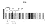
- the signal M_MAN is used by the photocell Slaves as a sync signal, i.e. a time reference against which to calculate the instant for turning on or off the emitting and receiving stages of the light beam.
- the situation is as in Fig. 5 .
- the pair FF1 is activated (receiver + transmitter) in the time interval ON_FF1, while the pair FF2 is turned off.
- the pair FF2 is active (receiver + transmitter) in the time interval ON_FF2, when the pair FF1 is by this time disabled. Note that this management also eliminates the problem of interference between different pairs of photocells, because the only active beam is that of the corresponding transmitter.
- the receiver photocell Slave stores the state of the beam, interrupted or free, during the intervals ON_FF1, ON_FF2, and will forward it to the Master during his transmission turn with a packet M_Sn, see Fig. 3 .
- the system implements an automatic adaptation.
- the Master then gives orders and receives messages from the photocell Slaves for coordinating a calibration phase of each group of photocells.
- the Master orders the transmitter-photocell (block AA) to transmit a test signal (see signal SG), consisting of three pulses: a calibration pulse and two standard power pulses. It then verifies (block BB) whether the receiver photocell has been able to receive the calibration impulse. If so (block DC), the receiver photocell informs the Master, which will send to the transmitter photocell Slave the proper power value to set the optical transmitter with, i.e. a power equal to that of the last two pulses. If not (block DD) the transmitter photocell will transmit with more power. The procedure is iterated (block EE) for all pairs of photocells, and for each photocell then the power settings are stored.
- a transmission power is set. This power may not be as narrow as possible, causing unnecessary consumption, or, because of the variation in environmental conditions or the sudden appearance of an obstacle, it could happen that the transmission power of the Slave is too low to allow reliable communication to the Master. Moreover, given that for consumption issues the power in transmission is not much higher than is strictly necessary, all devices can not be located but in fixed positions throughout their lifetime.
- the invention solves these problems by setting the power transmission variable during operation. One can get that consumption is always as low as possible, and at the same time that all Slaves properly communicate with the Master.
- the Master always transmits at fixed power known to the Slaves. Consequently, each Slave can estimate the attenuation introduced by the transmission channel and adjust the transmission power in such a manner that at any time, against any change in external conditions, the power received by the Master appears roughly constant, i.e. fixed to a predetermined value. This estimate is greatly simplified if the transmitted power of the Master is fixed to a determined value.
- the invention adopts other transmission methods for the optics of the photocell Slaves, always to decrease energy consumption and to respond appropriately to the needs of the system. Specifically:
- the Slave implementing the sensitive edge is a safety device, and therefore uses e.g. the same communication strategies with the Master of a photocell receiver Slave.
- the sensitive edge Slave can have a battery and a solar panel, or just the battery. To save the battery onboard as much as possible, the control means of the sensitive edge activate the obstacle detection circuitry only when the system is performing a maneuver, while they turn it off otherwise.
- the network device that consumes the most is the flashing light.
- the invention uses the following strategy (see Figure 6 ).
- a light sensor is used, e.g. a photo-diode or the solar panel of the device itself, to adjust the brightness of the flashing so as to make the light thereof visible when the sun or other element lights it up, and not to have too much light when there is shadow or at night.
- a rule can be that the flashing occurs with power (brightness) inversely proportional to the energy supplied by the solar cell (or by the state of charge of the battery or by a light detector means), which is proportional to the illumination of the place.
- the device By setting a switch in the flasher Slave one can set the device as a courtesy light, turning on the light only at dusk/night using the solar panel as a sensor or a photodiode.
- thresholds of ambient light may be set, for example four thresholds of decreasing light, see Fig. 6 .
- Block A It is verified (Block A) if the ambient light exceeds the first threshold (the larger one). If so, (Block B) the state of charge of the battery is verified: if it is charged the power of the flasher is set high (block C), otherwise (Block E) at medium power. If a threshold is not exceeded, the light level is compared with a lower threshold (blocks D and F) and for the flasher an always lower power (blocks E and G) is set for the use. If none of the thresholds is exceeded (Block H) the power of the flashing will be the least. Finally (block L) the flasher is actually turned on at the calculated power, and after a timer phase (M block) the flasher is turned off (block N).
- M block timer phase
Landscapes
- Engineering & Computer Science (AREA)
- Computer Networks & Wireless Communication (AREA)
- Signal Processing (AREA)
- Human Computer Interaction (AREA)
- Automation & Control Theory (AREA)
- Selective Calling Equipment (AREA)
- Power-Operated Mechanisms For Wings (AREA)
- Operating, Guiding And Securing Of Roll- Type Closing Members (AREA)
- Blinds (AREA)
Applications Claiming Priority (2)
| Application Number | Priority Date | Filing Date | Title |
|---|---|---|---|
| IT000168A ITVR20100168A1 (it) | 2010-08-06 | 2010-08-06 | Sistema di automazione |
| EP11754505.3A EP2601759B1 (de) | 2010-08-06 | 2011-08-04 | Automationssystem |
Related Parent Applications (3)
| Application Number | Title | Priority Date | Filing Date |
|---|---|---|---|
| EP11754505.3A Division EP2601759B1 (de) | 2010-08-06 | 2011-08-04 | Automationssystem |
| EP11754505.3A Division-Into EP2601759B1 (de) | 2010-08-06 | 2011-08-04 | Automationssystem |
| EP11754505.3 Division | 2011-08-04 |
Publications (2)
| Publication Number | Publication Date |
|---|---|
| EP2677696A2 true EP2677696A2 (de) | 2013-12-25 |
| EP2677696A3 EP2677696A3 (de) | 2014-03-26 |
Family
ID=43733251
Family Applications (5)
| Application Number | Title | Priority Date | Filing Date |
|---|---|---|---|
| EP11754505.3A Not-in-force EP2601759B1 (de) | 2010-08-06 | 2011-08-04 | Automationssystem |
| EP13183994.6A Withdrawn EP2677695A3 (de) | 2010-08-06 | 2011-08-04 | Verfahren zur Einstellung der optischen abgestrahlten Leistung durch eine Senderphotozelle zu einer Empfängerphotozelle |
| EP13184011.8A Withdrawn EP2677697A3 (de) | 2010-08-06 | 2011-08-04 | Übertragungsverfahren zwischen Komponenten und einer Steuereinheit eines Heimautomatisierungssystems |
| EP13184006.8A Withdrawn EP2677696A3 (de) | 2010-08-06 | 2011-08-04 | Verfahren zur Einstellung der optischen Leistung einer Taschenlampe eines Heimautomatisierungssystems |
| EP13184012.6A Withdrawn EP2677698A3 (de) | 2010-08-06 | 2011-08-04 | Bauteil eines Heimautomatisierungssystems, das mit einer Steuereinheit betrieben wird |
Family Applications Before (3)
| Application Number | Title | Priority Date | Filing Date |
|---|---|---|---|
| EP11754505.3A Not-in-force EP2601759B1 (de) | 2010-08-06 | 2011-08-04 | Automationssystem |
| EP13183994.6A Withdrawn EP2677695A3 (de) | 2010-08-06 | 2011-08-04 | Verfahren zur Einstellung der optischen abgestrahlten Leistung durch eine Senderphotozelle zu einer Empfängerphotozelle |
| EP13184011.8A Withdrawn EP2677697A3 (de) | 2010-08-06 | 2011-08-04 | Übertragungsverfahren zwischen Komponenten und einer Steuereinheit eines Heimautomatisierungssystems |
Family Applications After (1)
| Application Number | Title | Priority Date | Filing Date |
|---|---|---|---|
| EP13184012.6A Withdrawn EP2677698A3 (de) | 2010-08-06 | 2011-08-04 | Bauteil eines Heimautomatisierungssystems, das mit einer Steuereinheit betrieben wird |
Country Status (5)
| Country | Link |
|---|---|
| US (1) | US20130133262A1 (de) |
| EP (5) | EP2601759B1 (de) |
| AU (1) | AU2011287211A1 (de) |
| IT (1) | ITVR20100168A1 (de) |
| WO (1) | WO2012017411A1 (de) |
Families Citing this family (35)
| Publication number | Priority date | Publication date | Assignee | Title |
|---|---|---|---|---|
| US8909424B2 (en) † | 2012-10-11 | 2014-12-09 | Sram, Llc | Electronic shifting systems and methods |
| US9478378B2 (en) * | 2013-01-04 | 2016-10-25 | Schweitzer Engineering Laboratories, Inc. | Preventing out-of-synchronism reclosing between power systems |
| CA2955381C (en) | 2014-09-12 | 2022-03-22 | Exxonmobil Upstream Research Company | Discrete wellbore devices, hydrocarbon wells including a downhole communication network and the discrete wellbore devices and systems and methods including the same |
| WO2016106730A1 (zh) | 2014-12-31 | 2016-07-07 | 华为技术有限公司 | 主从网络休眠及唤醒的方法、装置及主从网络省电系统 |
| US10408047B2 (en) | 2015-01-26 | 2019-09-10 | Exxonmobil Upstream Research Company | Real-time well surveillance using a wireless network and an in-wellbore tool |
| WO2017008167A1 (en) * | 2015-07-15 | 2017-01-19 | Tsui Philip Y W | Wireless infrared safety sensor for garage door opener system |
| CN107306409B (zh) * | 2016-04-21 | 2020-06-12 | 富士通株式会社 | 参数确定方法、干扰分类识别方法及其装置 |
| US10590759B2 (en) | 2016-08-30 | 2020-03-17 | Exxonmobil Upstream Research Company | Zonal isolation devices including sensing and wireless telemetry and methods of utilizing the same |
| US10415376B2 (en) | 2016-08-30 | 2019-09-17 | Exxonmobil Upstream Research Company | Dual transducer communications node for downhole acoustic wireless networks and method employing same |
| US10344583B2 (en) | 2016-08-30 | 2019-07-09 | Exxonmobil Upstream Research Company | Acoustic housing for tubulars |
| US10697287B2 (en) | 2016-08-30 | 2020-06-30 | Exxonmobil Upstream Research Company | Plunger lift monitoring via a downhole wireless network field |
| US10364669B2 (en) | 2016-08-30 | 2019-07-30 | Exxonmobil Upstream Research Company | Methods of acoustically communicating and wells that utilize the methods |
| US10465505B2 (en) | 2016-08-30 | 2019-11-05 | Exxonmobil Upstream Research Company | Reservoir formation characterization using a downhole wireless network |
| US11828172B2 (en) | 2016-08-30 | 2023-11-28 | ExxonMobil Technology and Engineering Company | Communication networks, relay nodes for communication networks, and methods of transmitting data among a plurality of relay nodes |
| AU2017321142B2 (en) * | 2016-08-30 | 2019-08-08 | Exxonmobil Upstream Research Company | Methods of acoustically communicating and wells that utilize the methods |
| US10190410B2 (en) | 2016-08-30 | 2019-01-29 | Exxonmobil Upstream Research Company | Methods of acoustically communicating and wells that utilize the methods |
| US10526888B2 (en) | 2016-08-30 | 2020-01-07 | Exxonmobil Upstream Research Company | Downhole multiphase flow sensing methods |
| US10724363B2 (en) | 2017-10-13 | 2020-07-28 | Exxonmobil Upstream Research Company | Method and system for performing hydrocarbon operations with mixed communication networks |
| AU2018347466B2 (en) | 2017-10-13 | 2020-12-24 | Exxonmobil Upstream Research Company | Method and system for performing operations using communications |
| MX2020004982A (es) | 2017-10-13 | 2020-11-12 | Exxonmobil Upstream Res Co | Metodo y sistema para realizar comunicaciones usando solapamiento. |
| US10697288B2 (en) | 2017-10-13 | 2020-06-30 | Exxonmobil Upstream Research Company | Dual transducer communications node including piezo pre-tensioning for acoustic wireless networks and method employing same |
| CA3078835C (en) | 2017-10-13 | 2022-11-01 | Exxonmobil Upstream Research Company | Method and system for performing operations with communications |
| US10837276B2 (en) | 2017-10-13 | 2020-11-17 | Exxonmobil Upstream Research Company | Method and system for performing wireless ultrasonic communications along a drilling string |
| US10690794B2 (en) | 2017-11-17 | 2020-06-23 | Exxonmobil Upstream Research Company | Method and system for performing operations using communications for a hydrocarbon system |
| US12000273B2 (en) | 2017-11-17 | 2024-06-04 | ExxonMobil Technology and Engineering Company | Method and system for performing hydrocarbon operations using communications associated with completions |
| CN111247310B (zh) | 2017-11-17 | 2023-09-15 | 埃克森美孚技术与工程公司 | 沿着管状构件执行无线超声通信的方法和系统 |
| US10844708B2 (en) | 2017-12-20 | 2020-11-24 | Exxonmobil Upstream Research Company | Energy efficient method of retrieving wireless networked sensor data |
| US11156081B2 (en) | 2017-12-29 | 2021-10-26 | Exxonmobil Upstream Research Company | Methods and systems for operating and maintaining a downhole wireless network |
| CN111542679A (zh) | 2017-12-29 | 2020-08-14 | 埃克森美孚上游研究公司 | 用于监视和优化储层增产操作的方法和系统 |
| MX2020008276A (es) | 2018-02-08 | 2020-09-21 | Exxonmobil Upstream Res Co | Metodos de identificacion de pares de la red y auto-organizacion usando firmas tonales unicas y pozos que usan los metodos. |
| US11268378B2 (en) | 2018-02-09 | 2022-03-08 | Exxonmobil Upstream Research Company | Downhole wireless communication node and sensor/tools interface |
| US11952886B2 (en) | 2018-12-19 | 2024-04-09 | ExxonMobil Technology and Engineering Company | Method and system for monitoring sand production through acoustic wireless sensor network |
| US11293280B2 (en) | 2018-12-19 | 2022-04-05 | Exxonmobil Upstream Research Company | Method and system for monitoring post-stimulation operations through acoustic wireless sensor network |
| US11308019B2 (en) | 2019-05-30 | 2022-04-19 | D. H. Pace Company, Inc. | Systems and methods for door and dock equipment servicing |
| CN117202463A (zh) * | 2023-09-15 | 2023-12-08 | 深圳市傲柏科技有限公司 | 移动照明设备的控制方法及装置、电子设备、存储介质 |
Family Cites Families (21)
| Publication number | Priority date | Publication date | Assignee | Title |
|---|---|---|---|---|
| US6309216B1 (en) * | 1994-08-04 | 2001-10-30 | American Medical Technologies, Inc. | Curing system for photohardenable materials |
| US6294992B1 (en) * | 1995-08-17 | 2001-09-25 | Pittway Corp. | High power control signal transmission and low power data signal transmission in a wireless security system |
| PT1461790E (pt) | 2002-01-03 | 2005-11-30 | Vkr Holding A S | Metodo e sistema para transmissao de sinais usando saltos de frequencia |
| US6975203B2 (en) * | 2002-06-06 | 2005-12-13 | The Chamberlain Group, Inc. | Universal barrier operator transmitter |
| US8531266B2 (en) * | 2002-10-18 | 2013-09-10 | Johnson Controls Technology Company | System and method for providing an in-vehicle transmitter having multi-colored LED |
| SE0303584D0 (sv) * | 2003-12-30 | 2003-12-30 | Ericsson Telefon Ab L M | Method and arrangement in wireless ad hoc or multihop networks |
| JP4540377B2 (ja) * | 2004-03-25 | 2010-09-08 | パナソニック株式会社 | Ui表示装置及びui表示方法 |
| US7382063B2 (en) * | 2005-05-24 | 2008-06-03 | Wayne-Dalton Corp. | Uninterruptible power source for a barrier operator and related methods |
| US7684835B1 (en) * | 2005-07-12 | 2010-03-23 | Marvell Interntional Ltd. | Wake on wireless LAN schemes |
| US20070076645A1 (en) * | 2005-09-30 | 2007-04-05 | Vandrunen Paul J | Signal repeater system |
| US7447526B2 (en) * | 2005-10-28 | 2008-11-04 | Samsung Electronics Co., Ltd. | Power-saving method for wireless sensor network |
| JP4222366B2 (ja) * | 2005-12-19 | 2009-02-12 | 船井電機株式会社 | リモコン装置 |
| US7647078B2 (en) * | 2006-03-07 | 2010-01-12 | Samsung Electronics Co., Ltd. | Power-saving method for wireless sensor network |
| FR2903213B1 (fr) * | 2006-07-03 | 2008-10-03 | Somfy Sas | Procede de communication par radiofrequences dans une installation domotique |
| US8503343B2 (en) * | 2006-08-21 | 2013-08-06 | Panasonic Corporation | Wireless communication system, communication control method and communication node |
| WO2008024985A2 (en) * | 2006-08-25 | 2008-02-28 | Johnson Controls Technology Company | Integrated power source for interior led lighting |
| EP2007022B1 (de) | 2007-06-22 | 2010-05-12 | Feig Electronic GmbH | Funkverfahren für Tore |
| TWI362870B (en) * | 2008-05-29 | 2012-04-21 | Ind Tech Res Inst | System and method thereof for dynamically adjusting sleep/awake intervals of wireless network device |
| JP5255058B2 (ja) * | 2008-07-15 | 2013-08-07 | パナソニック株式会社 | 制御装置、端末装置及びこれらを用いた通信システム及び通信方法 |
| US20100130129A1 (en) * | 2008-11-25 | 2010-05-27 | Jue Chang | WLAN and bluetooth harmonization |
| JP4894076B2 (ja) * | 2009-11-10 | 2012-03-07 | 横河電機株式会社 | 中継装置及びこれを用いた無線制御ネットワーク管理システム |
-
2010
- 2010-08-06 IT IT000168A patent/ITVR20100168A1/it unknown
-
2011
- 2011-08-04 EP EP11754505.3A patent/EP2601759B1/de not_active Not-in-force
- 2011-08-04 AU AU2011287211A patent/AU2011287211A1/en not_active Abandoned
- 2011-08-04 EP EP13183994.6A patent/EP2677695A3/de not_active Withdrawn
- 2011-08-04 EP EP13184011.8A patent/EP2677697A3/de not_active Withdrawn
- 2011-08-04 EP EP13184006.8A patent/EP2677696A3/de not_active Withdrawn
- 2011-08-04 US US13/814,442 patent/US20130133262A1/en not_active Abandoned
- 2011-08-04 EP EP13184012.6A patent/EP2677698A3/de not_active Withdrawn
- 2011-08-04 WO PCT/IB2011/053488 patent/WO2012017411A1/en not_active Ceased
Non-Patent Citations (1)
| Title |
|---|
| None |
Also Published As
| Publication number | Publication date |
|---|---|
| EP2677698A3 (de) | 2014-03-19 |
| EP2677697A3 (de) | 2014-03-19 |
| EP2677696A3 (de) | 2014-03-26 |
| EP2601759A1 (de) | 2013-06-12 |
| WO2012017411A1 (en) | 2012-02-09 |
| EP2677698A2 (de) | 2013-12-25 |
| EP2677697A2 (de) | 2013-12-25 |
| EP2677695A3 (de) | 2014-03-19 |
| US20130133262A1 (en) | 2013-05-30 |
| AU2011287211A1 (en) | 2013-02-07 |
| EP2677695A2 (de) | 2013-12-25 |
| ITVR20100168A1 (it) | 2012-02-07 |
| EP2601759B1 (de) | 2016-04-06 |
Similar Documents
| Publication | Publication Date | Title |
|---|---|---|
| EP2677696A2 (de) | Verfahren zur Einstellung der optischen Leistung einer Taschenlampe eines Heimautomatisierungssystems | |
| US20130138757A1 (en) | Component addition/substitution method in a home automation wireless system | |
| US9284775B2 (en) | Safety system for moveable closures | |
| CA3001270C (en) | Wireless infrared safety sensor for garage door opener system | |
| US7852230B2 (en) | Method of communication and home automation installation for its implementation | |
| TWI475517B (zh) | 警報器 | |
| EP2119125B1 (de) | Bus-system und zugehöriges übertragungsprotokoll | |
| US8401059B2 (en) | Radio communication system | |
| JP2006106996A (ja) | 無線監視システム | |
| US20130169406A1 (en) | Wireless network for home automation | |
| CN101272649A (zh) | 热射线无线发送机 | |
| JP5537397B2 (ja) | 無線式センサシステム | |
| JP5712364B2 (ja) | 無線式センサシステム | |
| TWI463442B (zh) | 火災警報器及火災警報系統 | |
| NZ625620B2 (en) | Safety system for moveable closures |
Legal Events
| Date | Code | Title | Description |
|---|---|---|---|
| PUAI | Public reference made under article 153(3) epc to a published international application that has entered the european phase |
Free format text: ORIGINAL CODE: 0009012 |
|
| AC | Divisional application: reference to earlier application |
Ref document number: 2601759 Country of ref document: EP Kind code of ref document: P |
|
| AK | Designated contracting states |
Kind code of ref document: A2 Designated state(s): AL AT BE BG CH CY CZ DE DK EE ES FI FR GB GR HR HU IE IS IT LI LT LU LV MC MK MT NL NO PL PT RO RS SE SI SK SM TR |
|
| PUAL | Search report despatched |
Free format text: ORIGINAL CODE: 0009013 |
|
| AK | Designated contracting states |
Kind code of ref document: A3 Designated state(s): AL AT BE BG CH CY CZ DE DK EE ES FI FR GB GR HR HU IE IS IT LI LT LU LV MC MK MT NL NO PL PT RO RS SE SI SK SM TR |
|
| RIC1 | Information provided on ipc code assigned before grant |
Ipc: H04L 12/28 20060101AFI20140218BHEP |
|
| STAA | Information on the status of an ep patent application or granted ep patent |
Free format text: STATUS: THE APPLICATION IS DEEMED TO BE WITHDRAWN |
|
| 18D | Application deemed to be withdrawn |
Effective date: 20140927 |