EP2677566A1 - Battery pack - Google Patents
Battery pack Download PDFInfo
- Publication number
- EP2677566A1 EP2677566A1 EP13164583.0A EP13164583A EP2677566A1 EP 2677566 A1 EP2677566 A1 EP 2677566A1 EP 13164583 A EP13164583 A EP 13164583A EP 2677566 A1 EP2677566 A1 EP 2677566A1
- Authority
- EP
- European Patent Office
- Prior art keywords
- battery
- battery pack
- fuse
- control unit
- pack according
- Prior art date
- Legal status (The legal status is an assumption and is not a legal conclusion. Google has not performed a legal analysis and makes no representation as to the accuracy of the status listed.)
- Granted
Links
Images




Classifications
-
- H—ELECTRICITY
- H01—ELECTRIC ELEMENTS
- H01M—PROCESSES OR MEANS, e.g. BATTERIES, FOR THE DIRECT CONVERSION OF CHEMICAL ENERGY INTO ELECTRICAL ENERGY
- H01M50/00—Constructional details or processes of manufacture of the non-active parts of electrochemical cells other than fuel cells, e.g. hybrid cells
- H01M50/50—Current conducting connections for cells or batteries
- H01M50/572—Means for preventing undesired use or discharge
- H01M50/574—Devices or arrangements for the interruption of current
- H01M50/578—Devices or arrangements for the interruption of current in response to pressure
-
- H—ELECTRICITY
- H01—ELECTRIC ELEMENTS
- H01M—PROCESSES OR MEANS, e.g. BATTERIES, FOR THE DIRECT CONVERSION OF CHEMICAL ENERGY INTO ELECTRICAL ENERGY
- H01M10/00—Secondary cells; Manufacture thereof
- H01M10/42—Methods or arrangements for servicing or maintenance of secondary cells or secondary half-cells
- H01M10/425—Structural combination with electronic components, e.g. electronic circuits integrated to the outside of the casing
-
- H—ELECTRICITY
- H01—ELECTRIC ELEMENTS
- H01M—PROCESSES OR MEANS, e.g. BATTERIES, FOR THE DIRECT CONVERSION OF CHEMICAL ENERGY INTO ELECTRICAL ENERGY
- H01M50/00—Constructional details or processes of manufacture of the non-active parts of electrochemical cells other than fuel cells, e.g. hybrid cells
- H01M50/20—Mountings; Secondary casings or frames; Racks, modules or packs; Suspension devices; Shock absorbers; Transport or carrying devices; Holders
-
- H—ELECTRICITY
- H01—ELECTRIC ELEMENTS
- H01M—PROCESSES OR MEANS, e.g. BATTERIES, FOR THE DIRECT CONVERSION OF CHEMICAL ENERGY INTO ELECTRICAL ENERGY
- H01M50/00—Constructional details or processes of manufacture of the non-active parts of electrochemical cells other than fuel cells, e.g. hybrid cells
- H01M50/50—Current conducting connections for cells or batteries
- H01M50/572—Means for preventing undesired use or discharge
-
- H—ELECTRICITY
- H01—ELECTRIC ELEMENTS
- H01M—PROCESSES OR MEANS, e.g. BATTERIES, FOR THE DIRECT CONVERSION OF CHEMICAL ENERGY INTO ELECTRICAL ENERGY
- H01M50/00—Constructional details or processes of manufacture of the non-active parts of electrochemical cells other than fuel cells, e.g. hybrid cells
- H01M50/50—Current conducting connections for cells or batteries
- H01M50/572—Means for preventing undesired use or discharge
- H01M50/574—Devices or arrangements for the interruption of current
-
- H—ELECTRICITY
- H01—ELECTRIC ELEMENTS
- H01M—PROCESSES OR MEANS, e.g. BATTERIES, FOR THE DIRECT CONVERSION OF CHEMICAL ENERGY INTO ELECTRICAL ENERGY
- H01M50/00—Constructional details or processes of manufacture of the non-active parts of electrochemical cells other than fuel cells, e.g. hybrid cells
- H01M50/50—Current conducting connections for cells or batteries
- H01M50/572—Means for preventing undesired use or discharge
- H01M50/574—Devices or arrangements for the interruption of current
- H01M50/579—Devices or arrangements for the interruption of current in response to shock
-
- H—ELECTRICITY
- H01—ELECTRIC ELEMENTS
- H01M—PROCESSES OR MEANS, e.g. BATTERIES, FOR THE DIRECT CONVERSION OF CHEMICAL ENERGY INTO ELECTRICAL ENERGY
- H01M50/00—Constructional details or processes of manufacture of the non-active parts of electrochemical cells other than fuel cells, e.g. hybrid cells
- H01M50/50—Current conducting connections for cells or batteries
- H01M50/572—Means for preventing undesired use or discharge
- H01M50/574—Devices or arrangements for the interruption of current
- H01M50/581—Devices or arrangements for the interruption of current in response to temperature
-
- H—ELECTRICITY
- H01—ELECTRIC ELEMENTS
- H01M—PROCESSES OR MEANS, e.g. BATTERIES, FOR THE DIRECT CONVERSION OF CHEMICAL ENERGY INTO ELECTRICAL ENERGY
- H01M10/00—Secondary cells; Manufacture thereof
- H01M10/42—Methods or arrangements for servicing or maintenance of secondary cells or secondary half-cells
- H01M10/425—Structural combination with electronic components, e.g. electronic circuits integrated to the outside of the casing
- H01M2010/4271—Battery management systems including electronic circuits, e.g. control of current or voltage to keep battery in healthy state, cell balancing
-
- H—ELECTRICITY
- H01—ELECTRIC ELEMENTS
- H01M—PROCESSES OR MEANS, e.g. BATTERIES, FOR THE DIRECT CONVERSION OF CHEMICAL ENERGY INTO ELECTRICAL ENERGY
- H01M2200/00—Safety devices for primary or secondary batteries
- H01M2200/10—Temperature sensitive devices
- H01M2200/103—Fuse
-
- H—ELECTRICITY
- H01—ELECTRIC ELEMENTS
- H01M—PROCESSES OR MEANS, e.g. BATTERIES, FOR THE DIRECT CONVERSION OF CHEMICAL ENERGY INTO ELECTRICAL ENERGY
- H01M2220/00—Batteries for particular applications
- H01M2220/20—Batteries in motive systems, e.g. vehicle, ship, plane
-
- H—ELECTRICITY
- H01—ELECTRIC ELEMENTS
- H01M—PROCESSES OR MEANS, e.g. BATTERIES, FOR THE DIRECT CONVERSION OF CHEMICAL ENERGY INTO ELECTRICAL ENERGY
- H01M50/00—Constructional details or processes of manufacture of the non-active parts of electrochemical cells other than fuel cells, e.g. hybrid cells
- H01M50/20—Mountings; Secondary casings or frames; Racks, modules or packs; Suspension devices; Shock absorbers; Transport or carrying devices; Holders
- H01M50/204—Racks, modules or packs for multiple batteries or multiple cells
- H01M50/207—Racks, modules or packs for multiple batteries or multiple cells characterised by their shape
- H01M50/209—Racks, modules or packs for multiple batteries or multiple cells characterised by their shape adapted for prismatic or rectangular cells
-
- Y—GENERAL TAGGING OF NEW TECHNOLOGICAL DEVELOPMENTS; GENERAL TAGGING OF CROSS-SECTIONAL TECHNOLOGIES SPANNING OVER SEVERAL SECTIONS OF THE IPC; TECHNICAL SUBJECTS COVERED BY FORMER USPC CROSS-REFERENCE ART COLLECTIONS [XRACs] AND DIGESTS
- Y02—TECHNOLOGIES OR APPLICATIONS FOR MITIGATION OR ADAPTATION AGAINST CLIMATE CHANGE
- Y02E—REDUCTION OF GREENHOUSE GAS [GHG] EMISSIONS, RELATED TO ENERGY GENERATION, TRANSMISSION OR DISTRIBUTION
- Y02E60/00—Enabling technologies; Technologies with a potential or indirect contribution to GHG emissions mitigation
- Y02E60/10—Energy storage using batteries
Definitions
- the present invention relates to a battery pack.
- battery cells are used as energy sources for mobile devices, electric vehicles, hybrid vehicles, and the like.
- the shape of the battery cells may be variously selected depending on the kind of external device to which the battery cell is applied.
- a small-sized mobile device such as a cellular phone can be operated with the power and capacity of a single battery cell for a certain period of time.
- a large-capacity battery module is configured by electrically connecting a plurality of battery cells so as to increase power and capacity.
- the battery module increases output voltage or current according to the number of battery cells built therein.
- a battery pack may be configured by electrically connecting a plurality of battery modules.
- the battery pack includes a battery control unit so as to control the state of each battery cell.
- the battery control unit may be operated to cut off current applied to a specific battery cell or battery module according to a signal received therefrom.
- a battery control unit transfers the sensed signal to first fuses, thereby cutting off electrical connections between battery modules.
- a battery pack includes an interlock circuit or separate circuit configured to operate first fuses positioned between battery modules, thereby cutting off electrical connections between the battery modules.
- a battery pack includes: a plurality of battery modules, each including a plurality of battery cells arranged in a direction; at least one first fuse between battery modules of the plurality of battery modules; a battery control unit connected to the at least one first fuse; and at least one sensing unit connected to the battery control unit, the battery control unit being configured to transfer a signal received from the at least one sensing unit to the at least one first fuse, and the at least one first fuse including a power cutoff unit at a region of a connection member connecting the battery modules to each other, and a case surrounding the power cutoff unit.
- Pressure or heat may be generated in the power cutoff unit by the signal transferred from the battery control unit.
- the at least one sensing unit may include an airbag impact sensor.
- the battery pack may further include an airbag control unit between the airbag impact sensor and the battery control unit.
- the airbag impact sensor may concurrently transfer the signal to the battery control unit and the airbag control unit.
- the airbag impact sensor may transfer the signal to the battery control unit through the airbag control unit.
- the at least one sensing unit may include an airbag impact sensor, a moisture sensor, and an impact sensor.
- the battery control unit may be connected to the power cutoff unit of the at least one first fuse by a signal input line.
- the battery pack may further include a second fuse on an output line of the battery module.
- the at least one first fuse and the second fuse may be operated concurrently or individually.
- the battery pack may further include a second fuse on an input line of the battery module.
- the battery pack may further include an interlock circuit configured to selectively control the at least one first fuse for repairing the battery pack.
- a rechargeable battery according to embodiments of the present invention is suited for application in an electric vehicle or a hybrid electric vehicle.
- FIG. 1 is a schematic perspective view of a battery pack according to an embodiment of the present invention.
- FIG. 2 is a perspective view of a first fuse of the battery pack of FIG. 1 .
- FIG. 3 is a schematic block diagram of a battery pack according to an embodiment of the present invention.
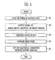
- FIG. 4 is a flowchart illustrating an operation of a battery pack according to an embodiment of the present invention.
- FIG. 5 is a flowchart illustrating an operation of a battery pack according to another embodiment of the present invention.
- FIG. 6 is a schematic block diagram of a battery pack according to another embodiment of the present invention.
- FIG. 1 is a schematic perspective view of a battery pack according to an embodiment of the present invention.
- FIG. 2 is a perspective view of a first fuse of the battery pack of FIG. 1 .
- a battery pack according to an embodiment of the present invention includes one or more battery modules 100, one or more first fuses 20, second fuses 30 and 40, a battery control unit (BCU) 200, and at least one sensing unit 50a, 50b, 50c, 60, 70a and 70b.
- BCU battery control unit
- the first fuse 20 includes a power cutoff unit 24 formed at a region of a connection member 22 connecting the battery modules 100 to each other, and a case 25 surrounding the power cutoff unit 24.
- the BCU 200 is connected to the power cutoff unit 24 of the first fuse 20 by a signal input line 21. Pressure or heat may be generated in the power cutoff unit 24 by a signal transferred from the BCU 200.
- the power cutoff unit 24, may be formed as a solenoid valve.
- connection member 22 is formed of a material having a structure vulnerable to heat and/or impact, and the connection member 22 is melted and/or broken by impact and/or heat generated in the power cutoff unit 24, such that the power between the battery modules 100 can be cut off.
- the power cutoff unit 24 may be exploded due to the pressure generated therein, and fragments of the exploded power cutoff unit 24 may be accommodated in the case 25 surrounding the power cutoff unit 24. Accordingly, if the first fuse 20 receives the signal from the BCU 200, the first fuse 20 may cut off current flowing between the battery modules 100 in a moment, thereby decreasing the voltage of the battery pack.
- the battery module 100 is a high-voltage and hig h-capacity battery module, and has a structure in which a plurality of battery cells 10 are arranged at an interval along a specific direction.
- the battery cells 10 may be formed in any of various suitable shapes, such as in a prismatic shape as shown and described herein.
- Each battery cell 10 may have an electrode assembly in which positive and negative electrode plates are disposed with a separator interposed therebetween, and may be configured to have a general structure for charging/discharging an amount (e.g., a predetermined amount) of power.
- positive and negative electrode terminals 11 and 12 are protruded from the top of each of the battery cells 10 while maintaining an interval.
- Each of the positive and negative electrode terminals 11 and 12 is formed having a shape of a bolt having screw threads formed thereon.
- the positive and negative electrode terminals 11 and 12 of each battery cell 10 are arranged next to the positive and negative electrode terminals 11 and 12 of another battery cell 10 adjacent to that battery cell 10 but with reversed polarity.
- a bus bar 15 is connected to the positive electrode terminal 11 of each battery cell 10 and the negative electrode terminal 12 of another battery cell 10 adjacent to that battery cell 10, and the positive and negative electrode terminals 11 and 12 are fastened with the bus bar 15 nuts 16.
- the positive and negative electrode terminals 11 and 12 of the battery cells 10 are hence fastened by the bus bars 15 to form the battery module 100 in which the plurality of battery cells 10 are electrically connected to one another.
- the fastening structure between the positive and negative electrode terminals 11 and 12 and the bus bars 15 is repeated, such that the plurality of battery cells 10 can be connected in series to one another.
- each first fuse 20 is provided on a connection member 22 connecting the adjacent battery modules 100 to each other. That is, the positive electrode terminal 11 of the battery cell 10 in one battery module 100 and the negative electrode terminal 12 of the battery cell 10 in another battery module 100 adjacent to the one battery module 100 are electrically connected by the connection member 22.
- the connection member 22 has openings 23 to couple to the positive electrode terminal 11 and the negative electrode terminal 12.
- the first fuse 20, in this embodiment, is formed at a region of the connection member 22, so as to cut off the electrical connection between the adjacent battery modules 100 as occasion demands.
- the positive and negative electrode second fuses 30 and 40 are installed on output lines 31 and 41 of the battery modules 100 at the ends of the battery modules 100 (e.g., the four battery modules 100) and connected to the BCU 200 by signal input lines 32 and 42, respectively.
- the first fuses 20 and the positive and negative electrode second fuses 30 and 40 are electrically connected to the BCU 200. Accordingly, the first fuses 20 and the positive and negative electrode second fuses 30 and 40 can be controlled and operated according to a signal from the BCU 200. Particularly, the first fuse 20 can cut off the electrical connection between the battery modules 100. In one embodiment, the signal may be transferred to the BCU 200 by the at least one sensing unit 50a, 50b, 50c, 60, 70a and 70b.
- the sensing units 50a, 50b, 50c, 60, 70a and 70b may include airbag impact sensors 50a, 50b and 50c, a moisture sensor 60, and impact sensors 70a and 70b. Accordingly, the BCU 200 may receive a signal output from the sensing units 50a, 50b, 50c, 60, 70a and 70b and transfer the received signal to the first fuses 20 and the positive and negative electrode second fuses 30 and 40.
- Other embodiments may include different kinds or combinations of sensors to suit requirements.
- an airbag control unit 50 is located between the BCU 200 and the one or more airbag impact sensors 50a, 50b and 50c.
- a signal output from the one or more airbag impact sensors 50a, 50b and 50c may be concurrently or simultaneously transferred to the BCU 200 and the airbag control unit 50.
- a signal output from the one or more airbag impact sensors 50a, 50b and 50c may be transferred to the BCU 200 through the airbag control unit 50.
- the first fuses 20 and the positive and negative electrode second fuses 30 and 40 may be operated concurrently or simultaneously, or individually.
- the BCU 200 may individually control the first fuses 20 and the positive and negative electrode second fuses 30 and 40 according to the signal output from the airbag impact sensors 50a, 50b, 50c, the impact sensors 70a and 70b, and the moisture sensor 60.
- a few tens of battery cells 10 may be connected in the battery pack, and the BCU 200 is configured to control the state of each of the battery cells 10.
- the battery cells 10 When the battery pack is charged, the battery cells 10 may be charged and discharged to different energy levels while being repeatedly charged and discharged several times. If battery cells 10 of the plurality of battery cells 10 are discharged to different energy level and then charged again, the energy levels of the charged battery cells 10 may also be different from one another. If the charge and discharge are repeated several times in this state, some of the battery cells 10 may be overdischarged, and the potential to be used may become 0 V or less. If a user continuously discharges or uses the battery cells 10, a phenomenon in which the potentials of the battery cells 10 are changed may occur.
- the battery cells 10 with different energy levels When the battery cells 10 with different energy levels are charged in the state that they are connected in series to one another, the battery cells 10 with relatively high energy levels transfer a charging completion signal to a charger before the battery cells 10 with relatively low energy levels reach the charged state. Accordingly, the charger completes the charging of the battery cells 10. Further, before the overdischarged battery cells 10 reach a completely charged state, the other battery cells 10 reach an overdischarging state. That is, some of the plurality of battery cells 10 repeat incomplete charging-overdischarging or battery reversal, and the other battery cells 10 repeat complete charging or overcharge-incomplete discharging. As a result, the battery cells 10 are damaged.
- a large-capacity battery pack may be provided with the BCU 200 for managing the state of each of the battery cells 10 so as to reduce damage of the battery cells 10.
- the first fuses 20 and the second fuses 30 and 40 may be connected to the BCU 200 so as to cut off current in the failure of the battery pack.
- the plurality of sensing units 50a, 50b, 50c, 60, 70a and 70b may be connected to the BCU 200 for transferring signals to the BCU 200 in the failure of the battery cells 10.
- FIG. 3 is a schematic block diagram of a battery pack according to an embodiment of the present invention.
- a battery pack according to an embodiment of the present invention includes the battery modules 100, the first fuses 20, and the positive and negative electrode second fuses 30 and 40.
- Each of the battery modules 100 includes the plurality of battery cells 10 (see FIG. 1 ), and the battery pack, in one embodiment, includes four battery modules 100, for example.
- the first fuse 20 is provided to the connection member 22 electrically connecting the battery modules 100 to each other.
- the positive and negative electrode second fuses 30 and 40 are installed on the output lines 31 and 41 of the battery modules 100, respectively.
- Each of the first fuses 20 and the positive and negative electrode second fuses 30 and 40 is electrically connected to the BCU 200.
- the BCU 200 is electrically connected to the airbag impact sensors 50a, 50b and 50c, the moisture sensor 60, and the impact sensors 70a and 70b.
- the airbag impact sensors 50a, 50b and 50c may concurrently or simultaneously transfer a signal output therefrom to the airbag control unit 50 and the BCU 200. Accordingly, if the signal is output from the airbag impact sensors 50a, 50b and 50c, an airbag can operate and concurrently or simultaneously cut off the electrical connection between the battery modules 100. In one embodiment, the airbag impact sensors 50a, 50b and 50c may transfer the output signal to the BCU 200 through the airbag control unit 50.
- the BCU 200 may control the first fuses 20 and the positive and negative electrode second fuses 30 and 40 according to the signal output from the plurality of sensing units 50a, 50b, 50c, 60, 70a and 70b. That is, the BCU 200 may cut off the electrical connection between the battery modules 100 by transferring the signal output from at least one of the sensing units 50a, 50b, 50c, 60, 70a and 70b to the first fuses 20. The BCU 200 may cut off the power of the battery pack itself by transferring the signal output from at least one of the sensing units 50a, 50b, 50c, 60, 70a and 70b to the positive and negative electrode second fuses 30 and 40.
- the voltage of the battery pack can be decreased by 1/4. Accordingly, when the insulation of the battery pack is broken due to impact or submergence, the output voltage of the battery pack is decreased to the voltage level of any one battery module 100, so that it is possible to reduce a risk of fire or electrical shock, thereby improving the safety of the battery pack.
- the second fuses 30 and 40 when at least one of the sensing units 50a, 50b, 50c, 60, 70a and 70b outputs a signal, the second fuses 30 and 40 are operated according to the signal output from the sensing units 50a, 50b, 50c, 60, 70a and 70b, thereby cutting off the entire power of the battery pack.
- the first fuses 20 and the positive and negative electrode second fuses 30 and 40 may be controlled to operate individually, or concurrently or simultaneously.
- FIG. 4 is a flowchart illustrating an operation of a battery pack according to an embodiment of the present invention.
- the power of the battery pack is first turned on (S1).
- the airbag impact sensors 50a, 50b and 50c, the moisture sensor 60, and the impact sensors 70a and 70b, which are connected to the BCU 200, are operated by the power of the battery pack.
- the sensing units 50a, 50b, 50c, 60, 70a and 70b do not output a signal.
- damage of the battery pack i.e. when the impact or moisture is sensed in the battery pack, the sensing units 50a, 50b, 50c, 60, 70a and 70b output a signal (S2).
- the output signal of the sensed impact or moisture is transferred to the BCU 200 (S3). Then, the BCU 200 transfers the signal to the first fuses 20 to operate the first fuses 20 (S4). When operated, the first fuses 20 cut off electrical connections between the battery modules 100 (S5).
- the first fuse 20, in one embodiment, is provided to the connection member 22 connecting the battery modules 100 to each other such that the signal output from the sensing units 50a, 50b, 50c, 60, 70a and 70b may be transferred to each of the first fuses 20 through the BCU 200.
- the voltage of the battery pack can be decreased by cutting off the flow of current between the battery modules 100. For example, when the insulation of the battery pack is broken, the electrical connections between the battery modules 100 may be cut off, such that a risk caused by electrical shock is prevented or reduced.
- FIG. 5 is a flowchart illustrating an operation of a battery pack according to another embodiment of the present invention.
- the signal of the airbag impact sensors 50a, 50b and 50c is output (S11).
- the output signal may be concurrently or simultaneously transferred to the airbag control unit 50 and the BCU 200 (S12).
- the airbag may be operated (S12') according to the signal transferred to the airbag control unit 50.
- the signal transferred to the BCU 200 is transferred to the first fuses 20 so that the first fuses 20 are operated (S13).
- the signal generated from the airbag impact sensors 50a, 50b and 50c is transferred to the first fuses 20 through the BCU 200, the first fuses 20 are operated and the electrical connections between the battery modules 100 are thereby cut off (S14).
- the output voltage of the battery pack is decreased to the voltage level of any one battery module 100, such that a risk of fire or electrical shock is prevented or reduced, thereby improving the safety of the battery pack.
- FIG. 6 is a schematic block diagram of a battery pack according to another embodiment of the present invention.
- the battery pack according to another embodiment of the present invention may further include an interlock circuit 80'.
- interlock circuit 80' description of the same components as described above will be omitted.
- the battery pack including the interlock circuit 80' can selectively control first fuses 20' in the repair of the battery pack. That is, the first fuses 20' are operated without a signal from a BCU 200' in the repair of the battery pack, such that it is possible to cut off power between battery modules 100' of the battery pack.
- the configuration and operation of the fuses are not limited to the above description and accompanying drawings, but, rather, it will be apparent to those skilled in the art that the fuses may include any other suitable fuses.
Landscapes
- Chemical & Material Sciences (AREA)
- Chemical Kinetics & Catalysis (AREA)
- Electrochemistry (AREA)
- General Chemical & Material Sciences (AREA)
- Engineering & Computer Science (AREA)
- Microelectronics & Electronic Packaging (AREA)
- Manufacturing & Machinery (AREA)
- Battery Mounting, Suspending (AREA)
- Connection Of Batteries Or Terminals (AREA)
- Electric Propulsion And Braking For Vehicles (AREA)
- Secondary Cells (AREA)
- Charge And Discharge Circuits For Batteries Or The Like (AREA)
Abstract
Description
- The present invention relates to a battery pack.
- In general, battery cells are used as energy sources for mobile devices, electric vehicles, hybrid vehicles, and the like. The shape of the battery cells may be variously selected depending on the kind of external device to which the battery cell is applied.
- A small-sized mobile device such as a cellular phone can be operated with the power and capacity of a single battery cell for a certain period of time. However, in a case where long-time driving and high-power driving are necessary, such as for an electric vehicle, a hybrid vehicle, or the like, which has large power consumption, a large-capacity battery module is configured by electrically connecting a plurality of battery cells so as to increase power and capacity. The battery module increases output voltage or current according to the number of battery cells built therein.
- A battery pack may be configured by electrically connecting a plurality of battery modules. The battery pack includes a battery control unit so as to control the state of each battery cell. The battery control unit may be operated to cut off current applied to a specific battery cell or battery module according to a signal received therefrom.
- According to an aspect of the present invention, in a battery pack, when a sensing unit senses that the battery pack is damaged, a battery control unit transfers the sensed signal to first fuses, thereby cutting off electrical connections between battery modules.
- According to another aspect of the present invention, a battery pack includes an interlock circuit or separate circuit configured to operate first fuses positioned between battery modules, thereby cutting off electrical connections between the battery modules.
- According to an embodiment of the present invention, a battery pack includes: a plurality of battery modules, each including a plurality of battery cells arranged in a direction; at least one first fuse between battery modules of the plurality of battery modules; a battery control unit connected to the at least one first fuse; and at least one sensing unit connected to the battery control unit, the battery control unit being configured to transfer a signal received from the at least one sensing unit to the at least one first fuse, and the at least one first fuse including a power cutoff unit at a region of a connection member connecting the battery modules to each other, and a case surrounding the power cutoff unit.
- Pressure or heat may be generated in the power cutoff unit by the signal transferred from the battery control unit.
- The at least one sensing unit may include an airbag impact sensor.
- The battery pack may further include an airbag control unit between the airbag impact sensor and the battery control unit.
- The airbag impact sensor may concurrently transfer the signal to the battery control unit and the airbag control unit.
- The airbag impact sensor may transfer the signal to the battery control unit through the airbag control unit.
- The at least one sensing unit may include an airbag impact sensor, a moisture sensor, and an impact sensor.
- The battery control unit may be connected to the power cutoff unit of the at least one first fuse by a signal input line.
- The battery pack may further include a second fuse on an output line of the battery module.
- The at least one first fuse and the second fuse may be operated concurrently or individually.
- The battery pack may further include a second fuse on an input line of the battery module.
- The battery pack may further include an interlock circuit configured to selectively control the at least one first fuse for repairing the battery pack.
- According to an aspect of embodiments of the present invention, when the insulation of the battery pack is broken due to impact or submergence, or as occasion demands, the output voltage of the battery pack is decreased to the voltage level of any one battery module, such that a risk of fire or electrical shock is prevented or reduced, thereby improving the safety of the battery pack. As such, a rechargeable battery according to embodiments of the present invention is suited for application in an electric vehicle or a hybrid electric vehicle.
- At least some of the above and other features of the invention are set out in the claims.
- The accompanying drawings, together with the description, illustrate some embodiments of the present invention, and, together, serve to explain aspects and principles of the present invention.
-
FIG. 1 is a schematic perspective view of a battery pack according to an embodiment of the present invention. -
FIG. 2 is a perspective view of a first fuse of the battery pack ofFIG. 1 . -
FIG. 3 is a schematic block diagram of a battery pack according to an embodiment of the present invention. -
FIG. 4 is a flowchart illustrating an operation of a battery pack according to an embodiment of the present invention. -
FIG. 5 is a flowchart illustrating an operation of a battery pack according to another embodiment of the present invention. -
FIG. 6 is a schematic block diagram of a battery pack according to another embodiment of the present invention. - In the following detailed description, certain embodiments of the present invention are shown and described, simply by way of illustration. As those skilled in the art would realize, the described embodiments may be modified in various different ways, all without departing from the scope of the present invention. Accordingly, the drawings and description are to be regarded as illustrative in nature and not restrictive. In addition, when an element is referred to as being "on" another element, it may be directly on the another element or indirectly on the another element with one or more intervening elements interposed therebetween. Also, when an element is referred to as being "connected to" another element, it may be directly connected to the another element or indirectly connected to the another element with one or more intervening elements connected therebetween. Hereinafter, like reference numerals refer to like elements. In the drawings, the thicknesses or sizes of components or layers may be exaggerated for clarity or purposes of illustration and not necessarily drawn to scale.
-
FIG. 1 is a schematic perspective view of a battery pack according to an embodiment of the present invention.FIG. 2 is a perspective view of a first fuse of the battery pack ofFIG. 1 . - Referring to
FIGS. 1 and2 , a battery pack according to an embodiment of the present invention includes one ormore battery modules 100, one or morefirst fuses 20,second fuses sensing unit - In this embodiment, the
first fuse 20 includes apower cutoff unit 24 formed at a region of aconnection member 22 connecting thebattery modules 100 to each other, and acase 25 surrounding thepower cutoff unit 24. The BCU 200 is connected to thepower cutoff unit 24 of thefirst fuse 20 by asignal input line 21. Pressure or heat may be generated in thepower cutoff unit 24 by a signal transferred from theBCU 200. Thepower cutoff unit 24, may be formed as a solenoid valve. - If the BCU 200 transfers a signal to the
power cutoff unit 24 to cut off power, pressure or heat is generated in thepower cutoff unit 24, and theconnection member 22 is melted. Accordingly, thebattery modules 100 can be electrically disconnected from each other. In this embodiment, theconnection member 22 is formed of a material having a structure vulnerable to heat and/or impact, and theconnection member 22 is melted and/or broken by impact and/or heat generated in thepower cutoff unit 24, such that the power between thebattery modules 100 can be cut off. - In this embodiment, the
power cutoff unit 24 may be exploded due to the pressure generated therein, and fragments of the explodedpower cutoff unit 24 may be accommodated in thecase 25 surrounding thepower cutoff unit 24. Accordingly, if thefirst fuse 20 receives the signal from theBCU 200, thefirst fuse 20 may cut off current flowing between thebattery modules 100 in a moment, thereby decreasing the voltage of the battery pack. - The
battery module 100 according to this embodiment is a high-voltage and hig h-capacity battery module, and has a structure in which a plurality ofbattery cells 10 are arranged at an interval along a specific direction. Thebattery cells 10 may be formed in any of various suitable shapes, such as in a prismatic shape as shown and described herein. - Each
battery cell 10 may have an electrode assembly in which positive and negative electrode plates are disposed with a separator interposed therebetween, and may be configured to have a general structure for charging/discharging an amount (e.g., a predetermined amount) of power. In this embodiment, positive andnegative electrode terminals battery cells 10 while maintaining an interval. Each of the positive andnegative electrode terminals - The positive and
negative electrode terminals battery cell 10 are arranged next to the positive andnegative electrode terminals battery cell 10 adjacent to thatbattery cell 10 but with reversed polarity. Abus bar 15 is connected to thepositive electrode terminal 11 of eachbattery cell 10 and thenegative electrode terminal 12 of anotherbattery cell 10 adjacent to thatbattery cell 10, and the positive andnegative electrode terminals bus bar 15 nuts 16. - The positive and
negative electrode terminals battery cells 10, are hence fastened by the bus bars 15 to form thebattery module 100 in which the plurality ofbattery cells 10 are electrically connected to one another. In thebattery module 100, the fastening structure between the positive andnegative electrode terminals battery cells 10 can be connected in series to one another. - In this embodiment, as illustrated in
FIG. 1 , fourbattery modules 100, for example, are electrically connected to one another, and the first fuses 20 are provided between therespective battery modules 100. Eachfirst fuse 20 is provided on aconnection member 22 connecting theadjacent battery modules 100 to each other. That is, thepositive electrode terminal 11 of thebattery cell 10 in onebattery module 100 and thenegative electrode terminal 12 of thebattery cell 10 in anotherbattery module 100 adjacent to the onebattery module 100 are electrically connected by theconnection member 22. Theconnection member 22 hasopenings 23 to couple to thepositive electrode terminal 11 and thenegative electrode terminal 12. Thefirst fuse 20, in this embodiment, is formed at a region of theconnection member 22, so as to cut off the electrical connection between theadjacent battery modules 100 as occasion demands. - The positive and negative electrode second fuses 30 and 40 are installed on
output lines battery modules 100 at the ends of the battery modules 100 (e.g., the four battery modules 100) and connected to theBCU 200 bysignal input lines - The first fuses 20 and the positive and negative electrode second fuses 30 and 40 are electrically connected to the
BCU 200. Accordingly, the first fuses 20 and the positive and negative electrode second fuses 30 and 40 can be controlled and operated according to a signal from theBCU 200. Particularly, thefirst fuse 20 can cut off the electrical connection between thebattery modules 100. In one embodiment, the signal may be transferred to theBCU 200 by the at least onesensing unit - In this embodiment, the
sensing units airbag impact sensors moisture sensor 60, andimpact sensors BCU 200 may receive a signal output from thesensing units - In this embodiment, an
airbag control unit 50 is located between theBCU 200 and the one or moreairbag impact sensors airbag impact sensors BCU 200 and theairbag control unit 50. In another embodiment, a signal output from the one or moreairbag impact sensors BCU 200 through theairbag control unit 50. - The first fuses 20 and the positive and negative electrode second fuses 30 and 40 may be operated concurrently or simultaneously, or individually. In one embodiment, the
BCU 200 may individually control the first fuses 20 and the positive and negative electrode second fuses 30 and 40 according to the signal output from theairbag impact sensors impact sensors moisture sensor 60. - In one embodiment, a few tens of
battery cells 10 may be connected in the battery pack, and theBCU 200 is configured to control the state of each of thebattery cells 10. When the battery pack is charged, thebattery cells 10 may be charged and discharged to different energy levels while being repeatedly charged and discharged several times. Ifbattery cells 10 of the plurality ofbattery cells 10 are discharged to different energy level and then charged again, the energy levels of the chargedbattery cells 10 may also be different from one another. If the charge and discharge are repeated several times in this state, some of thebattery cells 10 may be overdischarged, and the potential to be used may become 0 V or less. If a user continuously discharges or uses thebattery cells 10, a phenomenon in which the potentials of thebattery cells 10 are changed may occur. - When the
battery cells 10 with different energy levels are charged in the state that they are connected in series to one another, thebattery cells 10 with relatively high energy levels transfer a charging completion signal to a charger before thebattery cells 10 with relatively low energy levels reach the charged state. Accordingly, the charger completes the charging of thebattery cells 10. Further, before theoverdischarged battery cells 10 reach a completely charged state, theother battery cells 10 reach an overdischarging state. That is, some of the plurality ofbattery cells 10 repeat incomplete charging-overdischarging or battery reversal, and theother battery cells 10 repeat complete charging or overcharge-incomplete discharging. As a result, thebattery cells 10 are damaged. - Therefore, a large-capacity battery pack according to an embodiment of the present invention may be provided with the
BCU 200 for managing the state of each of thebattery cells 10 so as to reduce damage of thebattery cells 10. The first fuses 20 and the second fuses 30 and 40 may be connected to theBCU 200 so as to cut off current in the failure of the battery pack. The plurality ofsensing units BCU 200 for transferring signals to theBCU 200 in the failure of thebattery cells 10. -
FIG. 3 is a schematic block diagram of a battery pack according to an embodiment of the present invention. - Referring to
FIG. 3 , a battery pack according to an embodiment of the present invention includes thebattery modules 100, the first fuses 20, and the positive and negative electrode second fuses 30 and 40. - Each of the
battery modules 100 includes the plurality of battery cells 10 (seeFIG. 1 ), and the battery pack, in one embodiment, includes fourbattery modules 100, for example. Thefirst fuse 20 is provided to theconnection member 22 electrically connecting thebattery modules 100 to each other. The positive and negative electrode second fuses 30 and 40 are installed on theoutput lines battery modules 100, respectively. - Each of the first fuses 20 and the positive and negative electrode second fuses 30 and 40 is electrically connected to the
BCU 200. TheBCU 200 is electrically connected to theairbag impact sensors moisture sensor 60, and theimpact sensors - In one embodiment, the
airbag impact sensors airbag control unit 50 and theBCU 200. Accordingly, if the signal is output from theairbag impact sensors battery modules 100. In one embodiment, theairbag impact sensors BCU 200 through theairbag control unit 50. - Through the connection structure described above, the
BCU 200 may control the first fuses 20 and the positive and negative electrode second fuses 30 and 40 according to the signal output from the plurality ofsensing units BCU 200 may cut off the electrical connection between thebattery modules 100 by transferring the signal output from at least one of thesensing units BCU 200 may cut off the power of the battery pack itself by transferring the signal output from at least one of thesensing units - If all the first fuses 20 between the
battery modules 100 are operated, all the connections between thebattery modules 100 are cut off, and thus, in one embodiment, the voltage of the battery pack can be decreased by 1/4. Accordingly, when the insulation of the battery pack is broken due to impact or submergence, the output voltage of the battery pack is decreased to the voltage level of any onebattery module 100, so that it is possible to reduce a risk of fire or electrical shock, thereby improving the safety of the battery pack. - In one embodiment, when at least one of the
sensing units sensing units -
FIG. 4 is a flowchart illustrating an operation of a battery pack according to an embodiment of the present invention. - Referring to
FIG. 4 , the power of the battery pack is first turned on (S1). - Then, the
airbag impact sensors moisture sensor 60, and theimpact sensors BCU 200, are operated by the power of the battery pack. When impact or moisture is not sensed, thesensing units sensing units - The output signal of the sensed impact or moisture is transferred to the BCU 200 (S3). Then, the
BCU 200 transfers the signal to the first fuses 20 to operate the first fuses 20 (S4). When operated, the first fuses 20 cut off electrical connections between the battery modules 100 (S5). - The
first fuse 20, in one embodiment, is provided to theconnection member 22 connecting thebattery modules 100 to each other such that the signal output from thesensing units BCU 200. Thus, the voltage of the battery pack can be decreased by cutting off the flow of current between thebattery modules 100. For example, when the insulation of the battery pack is broken, the electrical connections between thebattery modules 100 may be cut off, such that a risk caused by electrical shock is prevented or reduced. -
FIG. 5 is a flowchart illustrating an operation of a battery pack according to another embodiment of the present invention. - Referring to
FIG. 5 , if an impact is sensed by at least one of theairbag impact sensors airbag impact sensors airbag control unit 50 and the BCU 200 (S12). In this case, the airbag may be operated (S12') according to the signal transferred to theairbag control unit 50. - The signal transferred to the
BCU 200 is transferred to the first fuses 20 so that the first fuses 20 are operated (S13). When the signal generated from theairbag impact sensors BCU 200, the first fuses 20 are operated and the electrical connections between thebattery modules 100 are thereby cut off (S14). - In one embodiment, when the insulation of the battery pack is broken due to impact or submergence, the output voltage of the battery pack is decreased to the voltage level of any one
battery module 100, such that a risk of fire or electrical shock is prevented or reduced, thereby improving the safety of the battery pack. -
FIG. 6 is a schematic block diagram of a battery pack according to another embodiment of the present invention. - Referring to
FIG. 6 , the battery pack according to another embodiment of the present invention may further include an interlock circuit 80'. In the following description of this embodiment, description of the same components as described above will be omitted. - The battery pack including the interlock circuit 80' can selectively control first fuses 20' in the repair of the battery pack. That is, the first fuses 20' are operated without a signal from a BCU 200' in the repair of the battery pack, such that it is possible to cut off power between battery modules 100' of the battery pack.
- According to embodiments of the present invention, the configuration and operation of the fuses are not limited to the above description and accompanying drawings, but, rather, it will be apparent to those skilled in the art that the fuses may include any other suitable fuses.
- While the present invention has been described in connection with certain embodiments of the invention, it is to be understood that the invention is not limited to the disclosed embodiments, but, on the contrary, is intended to cover various modifications and equivalent arrangements included within the scope of the appended claims, and equivalents thereof.
Claims (12)
- A battery pack comprising:a plurality of battery modules, each comprising a plurality of battery cells;at least one first fuse electrically connected between battery modules of the plurality of battery modules;a battery control unit connected to the at least one first fuse; andat least one sensing unit connected to the battery control unit,wherein the battery control unit is adapted to supply a signal to the at least one first fuse upon receipt of a signal from the sensing unit, andwherein the at least one first fuse comprises a power cutoff unit situated in a portion of a connection member electrically connecting the battery modules to each other, and a case surrounding the power cutoff unit.
- A battery pack according to claim 1, wherein pressure or heat is generated in the power cutoff unit by the signal transferred from the battery control unit.
- A battery pack according to claim 1 or 2, wherein the at least one sensing unit comprises an airbag impact sensor.
- A battery pack according to claim 3, further comprising an airbag control unit between the airbag impact sensor and the battery control unit.
- A battery pack according to claim 4, wherein the airbag impact sensor is adapted to transfer a signal to the battery control unit and the airbag control unit concurrently.
- A battery pack according to claim 4, wherein the airbag impact sensor is adapted to transfer a signal to the battery control unit through the airbag control unit.
- A battery pack according to any preceding claim, wherein the at least one sensing unit comprises an airbag impact sensor, a moisture sensor, and an impact sensor.
- A battery pack according to any preceding claim, wherein the battery control unit is connected to the power cutoff unit of the at least one first fuse by a signal input line.
- A battery pack according to any preceding claim, further comprising a second fuse on an output line of the battery module.
- A battery pack according to claim 9, adapted such that the at least one first fuse and the second fuse can be operated concurrently or individually.
- A battery pack according to any preceding claim, further comprising a second fuse on an input line of the battery module.
- A battery pack according to any preceding claim, further comprising an interlock circuit configured to selectively control the at least one first fuse for repairing the battery pack.
Applications Claiming Priority (1)
| Application Number | Priority Date | Filing Date | Title |
|---|---|---|---|
| KR1020120041485A KR20130118539A (en) | 2012-04-20 | 2012-04-20 | Battery pack |
Publications (2)
| Publication Number | Publication Date |
|---|---|
| EP2677566A1 true EP2677566A1 (en) | 2013-12-25 |
| EP2677566B1 EP2677566B1 (en) | 2018-10-17 |
Family
ID=48139833
Family Applications (1)
| Application Number | Title | Priority Date | Filing Date |
|---|---|---|---|
| EP13164583.0A Not-in-force EP2677566B1 (en) | 2012-04-20 | 2013-04-19 | Battery pack |
Country Status (5)
| Country | Link |
|---|---|
| US (1) | US9331325B2 (en) |
| EP (1) | EP2677566B1 (en) |
| JP (1) | JP6128760B2 (en) |
| KR (1) | KR20130118539A (en) |
| CN (1) | CN103378375B (en) |
Cited By (1)
| Publication number | Priority date | Publication date | Assignee | Title |
|---|---|---|---|---|
| WO2015149977A1 (en) * | 2014-04-04 | 2015-10-08 | Robert Bosch Gmbh | Method and device for increasing the safety during the use of battery systems |
Families Citing this family (24)
| Publication number | Priority date | Publication date | Assignee | Title |
|---|---|---|---|---|
| WO2014109284A1 (en) * | 2013-01-11 | 2014-07-17 | パナソニック株式会社 | Battery pack |
| KR101551000B1 (en) * | 2013-12-12 | 2015-09-07 | 현대자동차주식회사 | High voltage battery system for electric vehicle |
| CN104868511A (en) * | 2014-02-25 | 2015-08-26 | 观致汽车有限公司 | Battery component disconnection control system, battery component with system and vehicle |
| CN104917215B (en) * | 2014-03-13 | 2017-10-24 | 观致汽车有限公司 | Battery component open circuit control system and battery component and vehicle with it |
| EP3116057B1 (en) * | 2015-03-16 | 2019-10-30 | Kabushiki Kaisha Toshiba | Storage battery control apparatus and storage battery control method |
| KR102332443B1 (en) | 2015-06-03 | 2021-11-26 | 삼성에스디아이 주식회사 | Battery module |
| CN105154958B (en) * | 2015-09-22 | 2017-08-04 | 郑州磨料磨具磨削研究所有限公司 | A preparation method of an electroplated diamond grinding wheel with ordered abrasives |
| CN105857101A (en) * | 2016-03-31 | 2016-08-17 | 北京长城华冠汽车科技股份有限公司 | Cracking system and method for battery modules of electric automobile and electric automobile |
| KR102283791B1 (en) * | 2016-08-23 | 2021-07-30 | 삼성에스디아이 주식회사 | Protection apparatus for rechargeable battery |
| KR102260830B1 (en) * | 2016-11-08 | 2021-06-03 | 삼성에스디아이 주식회사 | Rechargeable battery pack |
| JP6524051B2 (en) * | 2016-12-09 | 2019-06-05 | 矢崎総業株式会社 | Conductor connection structure and conductive module |
| JP7309314B2 (en) * | 2017-05-31 | 2023-07-18 | 矢崎総業株式会社 | vehicle battery pack |
| WO2019069837A1 (en) * | 2017-10-05 | 2019-04-11 | 日立オートモティブシステムズ株式会社 | Battery module |
| DE102018200581A1 (en) * | 2018-01-15 | 2019-07-18 | Audi Ag | Battery, in particular for a motor vehicle, and method for operating a battery |
| KR102633757B1 (en) | 2018-02-05 | 2024-02-05 | 삼성에스디아이 주식회사 | Battery pack |
| IT201800002789A1 (en) * | 2018-02-19 | 2019-08-19 | Alfazero S P A | BATTERY PACK AND ONE ELECTRIC PROPULSION VEHICLE INCLUDING SAID BATTERY PACK |
| CN111971811B (en) * | 2018-02-19 | 2023-04-07 | 阿尔法泽诺股份公司 | Battery pack and electric vehicle including the same |
| CN117748057A (en) * | 2020-02-28 | 2024-03-22 | 比亚迪股份有限公司 | Battery pack and electric vehicle |
| KR102820188B1 (en) * | 2020-05-13 | 2025-06-13 | 주식회사 엘지에너지솔루션 | Battery Pack With Fuse-Box Bracket of Preventing Short Circuit |
| CN114520400A (en) * | 2020-11-20 | 2022-05-20 | 比亚迪股份有限公司 | Smart Connecting Sheets, Battery Packs and Vehicles |
| DE102021102049A1 (en) * | 2021-01-29 | 2022-08-04 | Audi Aktiengesellschaft | Battery arrangement, motor vehicle and method for operating a battery arrangement |
| JP7667720B2 (en) * | 2021-09-29 | 2025-04-23 | 株式会社Aescジャパン | Fuse device and battery module |
| US12548856B2 (en) | 2022-10-06 | 2026-02-10 | Ford Global Technologies, Llc | Thermal barrier integrated busbar systems for traction battery packs |
| IT202300024903A1 (en) * | 2023-11-23 | 2025-05-23 | Ferrari Spa | THERMAL PROPAGATION MANAGEMENT SYSTEM IN AN ELECTRIC BATTERY |
Citations (4)
| Publication number | Priority date | Publication date | Assignee | Title |
|---|---|---|---|---|
| JP2009158219A (en) * | 2007-12-26 | 2009-07-16 | Toyota Motor Corp | In-vehicle power storage device |
| EP2400628A2 (en) * | 2010-06-09 | 2011-12-28 | Samsung SDI Co., Ltd. | Battery protecting circuit, controlling method of the same and battery pack |
| KR20120010377A (en) * | 2010-07-26 | 2012-02-03 | 주식회사 엘지화학 | Apparatus and method for blocking high voltage of a vehicle battery pack |
| EP2482367A2 (en) * | 2011-01-31 | 2012-08-01 | SB LiMotive Co., Ltd. | Battery pack |
Family Cites Families (42)
| Publication number | Priority date | Publication date | Assignee | Title |
|---|---|---|---|---|
| JP2819828B2 (en) | 1990-11-30 | 1998-11-05 | 日産自動車株式会社 | Electric vehicle power supply |
| DE4234551C1 (en) | 1992-10-14 | 1994-01-20 | Daimler Benz Ag | Safety disconnection device for automobile battery - uses circuit breakers between series battery cells released in response to abnormal retardation resulting from accident |
| JPH06234342A (en) | 1993-02-10 | 1994-08-23 | Toyota Motor Corp | Central control device at the time of collision |
| KR100211570B1 (en) | 1995-12-20 | 1999-08-02 | 양재신 | Automatic power shut-off system for an automobile |
| KR0164337B1 (en) | 1995-12-29 | 1999-01-15 | 김태구 | Automotive power disconnect |
| KR19980013259U (en) | 1996-08-30 | 1998-06-05 | 김영귀 | Battery power cut-off device for electric vehicles |
| KR19980049720A (en) | 1996-12-20 | 1998-09-15 | 김영귀 | Airbag Interlock Power Disconnect Device |
| DE19854953C1 (en) | 1998-11-27 | 2000-09-21 | Volkswagen Ag | Battery on-board network with safety shutdown |
| US6296273B1 (en) | 2000-02-22 | 2001-10-02 | David G. Lewallen | Automobile airbag deactivation system |
| JP2003165406A (en) | 2001-12-03 | 2003-06-10 | Toyota Motor Corp | Vehicle power supply system |
| JP2004146307A (en) * | 2002-10-28 | 2004-05-20 | Solectron Japan Kk | Battery unit |
| JP3821085B2 (en) * | 2002-11-01 | 2006-09-13 | 新神戸電機株式会社 | Assembled battery |
| JP2004311290A (en) | 2003-04-09 | 2004-11-04 | Toyota Motor Corp | Battery pack temperature difference reduction device and battery pack |
| DE10361647A1 (en) | 2003-12-30 | 2005-08-04 | General Motors Corp., Detroit | Vehicle safety system for use in a vehicle with a fuel cell system and an electric power source where the fuel cell system is connected to the air bag control |
| JP4407430B2 (en) | 2004-08-27 | 2010-02-03 | トヨタ自動車株式会社 | Car |
| KR101040005B1 (en) | 2005-01-18 | 2011-06-08 | 현대자동차주식회사 | High Voltage Relay Control System Using Airbag Device of Hybrid Vehicle |
| KR20060102667A (en) | 2005-03-24 | 2006-09-28 | 삼성에스디아이 주식회사 | Secondary battery module |
| JP2006340577A (en) * | 2005-06-06 | 2006-12-14 | Nec Tokin Corp | Charging apparatus |
| KR100649570B1 (en) * | 2005-12-19 | 2006-11-27 | 삼성에스디아이 주식회사 | Battery Management Systems and Methods and Battery Systems |
| KR100834009B1 (en) | 2006-03-15 | 2008-06-02 | 한국철도기술연구원 | Battery with power off function in case of emergency |
| JP4884089B2 (en) | 2006-06-15 | 2012-02-22 | 三洋電機株式会社 | Power supply for vehicle |
| JP2008091183A (en) * | 2006-09-30 | 2008-04-17 | Sanyo Electric Co Ltd | Square battery and battery pack |
| US20080086250A1 (en) | 2006-10-05 | 2008-04-10 | Renesas Technology America, Inc. | Squib driver circuit diagnostic system and method |
| US20080157718A1 (en) | 2006-12-19 | 2008-07-03 | Honda Motor Co., Ltd. | Voltage monitor circuit |
| US7629543B2 (en) * | 2007-03-30 | 2009-12-08 | Delta Systems, Inc. | Switch assembly having a mechanically actuated override |
| JP4942602B2 (en) | 2007-09-26 | 2012-05-30 | 三洋電機株式会社 | Power supply for vehicle |
| JP2009194980A (en) * | 2008-02-13 | 2009-08-27 | Nec Tokin Corp | Secondary battery device |
| JP2009224262A (en) * | 2008-03-18 | 2009-10-01 | Calsonic Kansei Corp | Protection device for battery controller |
| JP5329851B2 (en) * | 2008-06-23 | 2013-10-30 | 株式会社東芝 | Power supply |
| JP5435928B2 (en) * | 2008-11-21 | 2014-03-05 | 矢崎総業株式会社 | Bus bar device and battery liquid temperature estimating device |
| KR101107115B1 (en) | 2008-12-01 | 2012-01-30 | 삼성에스디아이 주식회사 | Battery Management System and Battery Care Methods |
| JP5469909B2 (en) | 2009-04-20 | 2014-04-16 | 株式会社日立製作所 | Battery control system for vehicles |
| JP2010264830A (en) * | 2009-05-13 | 2010-11-25 | Suzuki Motor Corp | Electric vehicle |
| WO2010133176A1 (en) * | 2009-05-21 | 2010-11-25 | Byd Company Limited | Current fuse device and battery assembly comprising the same |
| CN201438449U (en) * | 2009-06-05 | 2010-04-14 | 比亚迪股份有限公司 | A current fuse and power battery |
| US20100305792A1 (en) | 2009-05-29 | 2010-12-02 | Ise Corporation | Dynamically Reconfigurable High Power Energy Storage for Hybrid Vehicles |
| FR2951320B1 (en) | 2009-10-08 | 2011-12-30 | Vehicules Electr Soc D | ELECTRIC BATTERY COMPRISING A PLURALITY OF ELECTRIC POWER GENERATING ELEMENTS |
| JP5805926B2 (en) | 2009-10-26 | 2015-11-10 | 矢崎総業株式会社 | Power circuit |
| US8258651B2 (en) | 2010-03-01 | 2012-09-04 | International Truck Intellectual Property Company, Llc | Methods and circuits for controlling a battery disconnect switch |
| JP5226753B2 (en) * | 2010-10-04 | 2013-07-03 | レノボ・シンガポール・プライベート・リミテッド | Charging system and charging method |
| JP5637878B2 (en) | 2011-01-27 | 2014-12-10 | 株式会社日立製作所 | Secondary battery system |
| JP5859228B2 (en) * | 2011-06-21 | 2016-02-10 | 矢崎総業株式会社 | Box |
-
2012
- 2012-04-20 KR KR1020120041485A patent/KR20130118539A/en not_active Ceased
- 2012-06-18 JP JP2012136658A patent/JP6128760B2/en active Active
-
2013
- 2013-02-06 US US13/760,865 patent/US9331325B2/en active Active
- 2013-04-08 CN CN201310119717.3A patent/CN103378375B/en active Active
- 2013-04-19 EP EP13164583.0A patent/EP2677566B1/en not_active Not-in-force
Patent Citations (4)
| Publication number | Priority date | Publication date | Assignee | Title |
|---|---|---|---|---|
| JP2009158219A (en) * | 2007-12-26 | 2009-07-16 | Toyota Motor Corp | In-vehicle power storage device |
| EP2400628A2 (en) * | 2010-06-09 | 2011-12-28 | Samsung SDI Co., Ltd. | Battery protecting circuit, controlling method of the same and battery pack |
| KR20120010377A (en) * | 2010-07-26 | 2012-02-03 | 주식회사 엘지화학 | Apparatus and method for blocking high voltage of a vehicle battery pack |
| EP2482367A2 (en) * | 2011-01-31 | 2012-08-01 | SB LiMotive Co., Ltd. | Battery pack |
Cited By (4)
| Publication number | Priority date | Publication date | Assignee | Title |
|---|---|---|---|---|
| WO2015149977A1 (en) * | 2014-04-04 | 2015-10-08 | Robert Bosch Gmbh | Method and device for increasing the safety during the use of battery systems |
| CN106463787A (en) * | 2014-04-04 | 2017-02-22 | 罗伯特·博世有限公司 | Method and device for increasing the safety during the use of battery systems |
| US10522878B2 (en) | 2014-04-04 | 2019-12-31 | Robert Bosch Gmbh | Method and device for increasing the safety during the use of battery systems |
| CN106463787B (en) * | 2014-04-04 | 2021-10-19 | 罗伯特·博世有限公司 | Method and apparatus for improving safety when using a battery system |
Also Published As
| Publication number | Publication date |
|---|---|
| US20130280560A1 (en) | 2013-10-24 |
| EP2677566B1 (en) | 2018-10-17 |
| KR20130118539A (en) | 2013-10-30 |
| US9331325B2 (en) | 2016-05-03 |
| JP2013225464A (en) | 2013-10-31 |
| CN103378375B (en) | 2017-09-22 |
| JP6128760B2 (en) | 2017-05-17 |
| CN103378375A (en) | 2013-10-30 |
Similar Documents
| Publication | Publication Date | Title |
|---|---|---|
| EP2677566B1 (en) | Battery pack | |
| US9490467B2 (en) | Battery pack | |
| US8471529B2 (en) | Battery fault tolerant architecture for cell failure modes parallel bypass circuit | |
| KR100914839B1 (en) | Battery Module of Improved Safety and Middle or Large-sized Battery Pack Containing the Same | |
| KR101404712B1 (en) | Battery Pack of Improved Safety | |
| US8859131B2 (en) | Battery module and battery pack including the same | |
| KR101130050B1 (en) | Middle or Large-sized Battery Pack of Improved Safety | |
| KR101359310B1 (en) | Battery Pack of Improved Safety | |
| US7911179B2 (en) | Charging/discharging apparatus | |
| US20120091964A1 (en) | Battery fault tolerant architecture for cell failure modes series bypass circuit | |
| CA2589892A1 (en) | Secondary battery module | |
| JP2017004968A (en) | Battery pack with improved safety | |
| US20150137767A1 (en) | Protection apparatus for rechargeable battery | |
| CN108140908A (en) | Accumulator plant and vehicle | |
| US20170237269A1 (en) | Battery charge-discharge balancing circuit assembly | |
| US20110101919A1 (en) | Lithium ion battery pack | |
| KR20160132633A (en) | Battery system and control method for connection of the same | |
| KR20190093514A (en) | Battery system for a battery-operated electric vehicle and method for utilizing a remaining range of same | |
| KR102465462B1 (en) | Battery switching device for slow or fast charging | |
| CN212435391U (en) | Battery double-layer protection circuit and battery device | |
| KR20060102667A (en) | Secondary battery module | |
| KR102078598B1 (en) | Modularized battery pack | |
| KR101123058B1 (en) | Wireless Device Using Universal Serial Bus for Charging and Discharging | |
| KR20230006166A (en) | Battery module |
Legal Events
| Date | Code | Title | Description |
|---|---|---|---|
| PUAI | Public reference made under article 153(3) epc to a published international application that has entered the european phase |
Free format text: ORIGINAL CODE: 0009012 |
|
| AK | Designated contracting states |
Kind code of ref document: A1 Designated state(s): AL AT BE BG CH CY CZ DE DK EE ES FI FR GB GR HR HU IE IS IT LI LT LU LV MC MK MT NL NO PL PT RO RS SE SI SK SM TR |
|
| AX | Request for extension of the european patent |
Extension state: BA ME |
|
| 17P | Request for examination filed |
Effective date: 20140625 |
|
| RBV | Designated contracting states (corrected) |
Designated state(s): AL AT BE BG CH CY CZ DE DK EE ES FI FR GB GR HR HU IE IS IT LI LT LU LV MC MK MT NL NO PL PT RO RS SE SI SK SM TR |
|
| STAA | Information on the status of an ep patent application or granted ep patent |
Free format text: STATUS: EXAMINATION IS IN PROGRESS |
|
| 17Q | First examination report despatched |
Effective date: 20170710 |
|
| GRAP | Despatch of communication of intention to grant a patent |
Free format text: ORIGINAL CODE: EPIDOSNIGR1 |
|
| STAA | Information on the status of an ep patent application or granted ep patent |
Free format text: STATUS: GRANT OF PATENT IS INTENDED |
|
| INTG | Intention to grant announced |
Effective date: 20180418 |
|
| GRAS | Grant fee paid |
Free format text: ORIGINAL CODE: EPIDOSNIGR3 |
|
| GRAA | (expected) grant |
Free format text: ORIGINAL CODE: 0009210 |
|
| STAA | Information on the status of an ep patent application or granted ep patent |
Free format text: STATUS: THE PATENT HAS BEEN GRANTED |
|
| AK | Designated contracting states |
Kind code of ref document: B1 Designated state(s): AL AT BE BG CH CY CZ DE DK EE ES FI FR GB GR HR HU IE IS IT LI LT LU LV MC MK MT NL NO PL PT RO RS SE SI SK SM TR |
|
| REG | Reference to a national code |
Ref country code: GB Ref legal event code: FG4D |
|
| REG | Reference to a national code |
Ref country code: CH Ref legal event code: EP |
|
| REG | Reference to a national code |
Ref country code: IE Ref legal event code: FG4D |
|
| REG | Reference to a national code |
Ref country code: DE Ref legal event code: R096 Ref document number: 602013045120 Country of ref document: DE Ref country code: AT Ref legal event code: REF Ref document number: 1055029 Country of ref document: AT Kind code of ref document: T Effective date: 20181115 |
|
| REG | Reference to a national code |
Ref country code: NL Ref legal event code: MP Effective date: 20181017 |
|
| REG | Reference to a national code |
Ref country code: LT Ref legal event code: MG4D |
|
| REG | Reference to a national code |
Ref country code: AT Ref legal event code: MK05 Ref document number: 1055029 Country of ref document: AT Kind code of ref document: T Effective date: 20181017 |
|
| PG25 | Lapsed in a contracting state [announced via postgrant information from national office to epo] |
Ref country code: NL Free format text: LAPSE BECAUSE OF FAILURE TO SUBMIT A TRANSLATION OF THE DESCRIPTION OR TO PAY THE FEE WITHIN THE PRESCRIBED TIME-LIMIT Effective date: 20181017 |
|
| PG25 | Lapsed in a contracting state [announced via postgrant information from national office to epo] |
Ref country code: ES Free format text: LAPSE BECAUSE OF FAILURE TO SUBMIT A TRANSLATION OF THE DESCRIPTION OR TO PAY THE FEE WITHIN THE PRESCRIBED TIME-LIMIT Effective date: 20181017 Ref country code: AT Free format text: LAPSE BECAUSE OF FAILURE TO SUBMIT A TRANSLATION OF THE DESCRIPTION OR TO PAY THE FEE WITHIN THE PRESCRIBED TIME-LIMIT Effective date: 20181017 Ref country code: BG Free format text: LAPSE BECAUSE OF FAILURE TO SUBMIT A TRANSLATION OF THE DESCRIPTION OR TO PAY THE FEE WITHIN THE PRESCRIBED TIME-LIMIT Effective date: 20190117 Ref country code: NO Free format text: LAPSE BECAUSE OF FAILURE TO SUBMIT A TRANSLATION OF THE DESCRIPTION OR TO PAY THE FEE WITHIN THE PRESCRIBED TIME-LIMIT Effective date: 20190117 Ref country code: IS Free format text: LAPSE BECAUSE OF FAILURE TO SUBMIT A TRANSLATION OF THE DESCRIPTION OR TO PAY THE FEE WITHIN THE PRESCRIBED TIME-LIMIT Effective date: 20190217 Ref country code: LT Free format text: LAPSE BECAUSE OF FAILURE TO SUBMIT A TRANSLATION OF THE DESCRIPTION OR TO PAY THE FEE WITHIN THE PRESCRIBED TIME-LIMIT Effective date: 20181017 Ref country code: FI Free format text: LAPSE BECAUSE OF FAILURE TO SUBMIT A TRANSLATION OF THE DESCRIPTION OR TO PAY THE FEE WITHIN THE PRESCRIBED TIME-LIMIT Effective date: 20181017 Ref country code: LV Free format text: LAPSE BECAUSE OF FAILURE TO SUBMIT A TRANSLATION OF THE DESCRIPTION OR TO PAY THE FEE WITHIN THE PRESCRIBED TIME-LIMIT Effective date: 20181017 Ref country code: HR Free format text: LAPSE BECAUSE OF FAILURE TO SUBMIT A TRANSLATION OF THE DESCRIPTION OR TO PAY THE FEE WITHIN THE PRESCRIBED TIME-LIMIT Effective date: 20181017 Ref country code: PL Free format text: LAPSE BECAUSE OF FAILURE TO SUBMIT A TRANSLATION OF THE DESCRIPTION OR TO PAY THE FEE WITHIN THE PRESCRIBED TIME-LIMIT Effective date: 20181017 |
|
| PG25 | Lapsed in a contracting state [announced via postgrant information from national office to epo] |
Ref country code: SE Free format text: LAPSE BECAUSE OF FAILURE TO SUBMIT A TRANSLATION OF THE DESCRIPTION OR TO PAY THE FEE WITHIN THE PRESCRIBED TIME-LIMIT Effective date: 20181017 Ref country code: RS Free format text: LAPSE BECAUSE OF FAILURE TO SUBMIT A TRANSLATION OF THE DESCRIPTION OR TO PAY THE FEE WITHIN THE PRESCRIBED TIME-LIMIT Effective date: 20181017 Ref country code: AL Free format text: LAPSE BECAUSE OF FAILURE TO SUBMIT A TRANSLATION OF THE DESCRIPTION OR TO PAY THE FEE WITHIN THE PRESCRIBED TIME-LIMIT Effective date: 20181017 Ref country code: PT Free format text: LAPSE BECAUSE OF FAILURE TO SUBMIT A TRANSLATION OF THE DESCRIPTION OR TO PAY THE FEE WITHIN THE PRESCRIBED TIME-LIMIT Effective date: 20190217 Ref country code: GR Free format text: LAPSE BECAUSE OF FAILURE TO SUBMIT A TRANSLATION OF THE DESCRIPTION OR TO PAY THE FEE WITHIN THE PRESCRIBED TIME-LIMIT Effective date: 20190118 |
|
| REG | Reference to a national code |
Ref country code: DE Ref legal event code: R097 Ref document number: 602013045120 Country of ref document: DE |
|
| PG25 | Lapsed in a contracting state [announced via postgrant information from national office to epo] |
Ref country code: DK Free format text: LAPSE BECAUSE OF FAILURE TO SUBMIT A TRANSLATION OF THE DESCRIPTION OR TO PAY THE FEE WITHIN THE PRESCRIBED TIME-LIMIT Effective date: 20181017 Ref country code: CZ Free format text: LAPSE BECAUSE OF FAILURE TO SUBMIT A TRANSLATION OF THE DESCRIPTION OR TO PAY THE FEE WITHIN THE PRESCRIBED TIME-LIMIT Effective date: 20181017 Ref country code: IT Free format text: LAPSE BECAUSE OF FAILURE TO SUBMIT A TRANSLATION OF THE DESCRIPTION OR TO PAY THE FEE WITHIN THE PRESCRIBED TIME-LIMIT Effective date: 20181017 |
|
| PLBE | No opposition filed within time limit |
Free format text: ORIGINAL CODE: 0009261 |
|
| STAA | Information on the status of an ep patent application or granted ep patent |
Free format text: STATUS: NO OPPOSITION FILED WITHIN TIME LIMIT |
|
| PG25 | Lapsed in a contracting state [announced via postgrant information from national office to epo] |
Ref country code: SK Free format text: LAPSE BECAUSE OF FAILURE TO SUBMIT A TRANSLATION OF THE DESCRIPTION OR TO PAY THE FEE WITHIN THE PRESCRIBED TIME-LIMIT Effective date: 20181017 Ref country code: RO Free format text: LAPSE BECAUSE OF FAILURE TO SUBMIT A TRANSLATION OF THE DESCRIPTION OR TO PAY THE FEE WITHIN THE PRESCRIBED TIME-LIMIT Effective date: 20181017 Ref country code: SM Free format text: LAPSE BECAUSE OF FAILURE TO SUBMIT A TRANSLATION OF THE DESCRIPTION OR TO PAY THE FEE WITHIN THE PRESCRIBED TIME-LIMIT Effective date: 20181017 Ref country code: EE Free format text: LAPSE BECAUSE OF FAILURE TO SUBMIT A TRANSLATION OF THE DESCRIPTION OR TO PAY THE FEE WITHIN THE PRESCRIBED TIME-LIMIT Effective date: 20181017 |
|
| 26N | No opposition filed |
Effective date: 20190718 |
|
| PG25 | Lapsed in a contracting state [announced via postgrant information from national office to epo] |
Ref country code: SI Free format text: LAPSE BECAUSE OF FAILURE TO SUBMIT A TRANSLATION OF THE DESCRIPTION OR TO PAY THE FEE WITHIN THE PRESCRIBED TIME-LIMIT Effective date: 20181017 |
|
| REG | Reference to a national code |
Ref country code: CH Ref legal event code: PL |
|
| REG | Reference to a national code |
Ref country code: BE Ref legal event code: MM Effective date: 20190430 |
|
| PG25 | Lapsed in a contracting state [announced via postgrant information from national office to epo] |
Ref country code: MC Free format text: LAPSE BECAUSE OF FAILURE TO SUBMIT A TRANSLATION OF THE DESCRIPTION OR TO PAY THE FEE WITHIN THE PRESCRIBED TIME-LIMIT Effective date: 20181017 Ref country code: LU Free format text: LAPSE BECAUSE OF NON-PAYMENT OF DUE FEES Effective date: 20190419 |
|
| PG25 | Lapsed in a contracting state [announced via postgrant information from national office to epo] |
Ref country code: CH Free format text: LAPSE BECAUSE OF NON-PAYMENT OF DUE FEES Effective date: 20190430 Ref country code: LI Free format text: LAPSE BECAUSE OF NON-PAYMENT OF DUE FEES Effective date: 20190430 |
|
| PG25 | Lapsed in a contracting state [announced via postgrant information from national office to epo] |
Ref country code: BE Free format text: LAPSE BECAUSE OF NON-PAYMENT OF DUE FEES Effective date: 20190430 |
|
| PG25 | Lapsed in a contracting state [announced via postgrant information from national office to epo] |
Ref country code: TR Free format text: LAPSE BECAUSE OF FAILURE TO SUBMIT A TRANSLATION OF THE DESCRIPTION OR TO PAY THE FEE WITHIN THE PRESCRIBED TIME-LIMIT Effective date: 20181017 |
|
| PG25 | Lapsed in a contracting state [announced via postgrant information from national office to epo] |
Ref country code: IE Free format text: LAPSE BECAUSE OF NON-PAYMENT OF DUE FEES Effective date: 20190419 |
|
| REG | Reference to a national code |
Ref country code: DE Ref legal event code: R079 Ref document number: 602013045120 Country of ref document: DE Free format text: PREVIOUS MAIN CLASS: H01M0002340000 Ipc: H01M0050572000 |
|
| PG25 | Lapsed in a contracting state [announced via postgrant information from national office to epo] |
Ref country code: CY Free format text: LAPSE BECAUSE OF FAILURE TO SUBMIT A TRANSLATION OF THE DESCRIPTION OR TO PAY THE FEE WITHIN THE PRESCRIBED TIME-LIMIT Effective date: 20181017 |
|
| PG25 | Lapsed in a contracting state [announced via postgrant information from national office to epo] |
Ref country code: MT Free format text: LAPSE BECAUSE OF FAILURE TO SUBMIT A TRANSLATION OF THE DESCRIPTION OR TO PAY THE FEE WITHIN THE PRESCRIBED TIME-LIMIT Effective date: 20181017 Ref country code: HU Free format text: LAPSE BECAUSE OF FAILURE TO SUBMIT A TRANSLATION OF THE DESCRIPTION OR TO PAY THE FEE WITHIN THE PRESCRIBED TIME-LIMIT; INVALID AB INITIO Effective date: 20130419 |
|
| PG25 | Lapsed in a contracting state [announced via postgrant information from national office to epo] |
Ref country code: MK Free format text: LAPSE BECAUSE OF FAILURE TO SUBMIT A TRANSLATION OF THE DESCRIPTION OR TO PAY THE FEE WITHIN THE PRESCRIBED TIME-LIMIT Effective date: 20181017 |
|
| P01 | Opt-out of the competence of the unified patent court (upc) registered |
Effective date: 20230530 |
|
| PGFP | Annual fee paid to national office [announced via postgrant information from national office to epo] |
Ref country code: FR Payment date: 20240328 Year of fee payment: 12 |
|
| PGFP | Annual fee paid to national office [announced via postgrant information from national office to epo] |
Ref country code: GB Payment date: 20240402 Year of fee payment: 12 |
|
| PGFP | Annual fee paid to national office [announced via postgrant information from national office to epo] |
Ref country code: DE Payment date: 20240328 Year of fee payment: 12 |
|
| REG | Reference to a national code |
Ref country code: DE Ref legal event code: R119 Ref document number: 602013045120 Country of ref document: DE |
|
| GBPC | Gb: european patent ceased through non-payment of renewal fee |
Effective date: 20250419 |
|
| PG25 | Lapsed in a contracting state [announced via postgrant information from national office to epo] |
Ref country code: DE Free format text: LAPSE BECAUSE OF NON-PAYMENT OF DUE FEES Effective date: 20251104 |
|
| PG25 | Lapsed in a contracting state [announced via postgrant information from national office to epo] |
Ref country code: GB Free format text: LAPSE BECAUSE OF NON-PAYMENT OF DUE FEES Effective date: 20250419 |
|
| PG25 | Lapsed in a contracting state [announced via postgrant information from national office to epo] |
Ref country code: FR Free format text: LAPSE BECAUSE OF NON-PAYMENT OF DUE FEES Effective date: 20250430 |