EP2677258A2 - Kühlschrank - Google Patents
Kühlschrank Download PDFInfo
- Publication number
- EP2677258A2 EP2677258A2 EP13173000.4A EP13173000A EP2677258A2 EP 2677258 A2 EP2677258 A2 EP 2677258A2 EP 13173000 A EP13173000 A EP 13173000A EP 2677258 A2 EP2677258 A2 EP 2677258A2
- Authority
- EP
- European Patent Office
- Prior art keywords
- door
- shelf
- guide
- hinge
- opening
- Prior art date
- Legal status (The legal status is an assumption and is not a legal conclusion. Google has not performed a legal analysis and makes no representation as to the accuracy of the status listed.)
- Granted
Links
Images


Classifications
-
- F—MECHANICAL ENGINEERING; LIGHTING; HEATING; WEAPONS; BLASTING
- F25—REFRIGERATION OR COOLING; COMBINED HEATING AND REFRIGERATION SYSTEMS; HEAT PUMP SYSTEMS; MANUFACTURE OR STORAGE OF ICE; LIQUEFACTION SOLIDIFICATION OF GASES
- F25D—REFRIGERATORS; COLD ROOMS; ICE-BOXES; COOLING OR FREEZING APPARATUS NOT OTHERWISE PROVIDED FOR
- F25D23/00—General constructional features
- F25D23/02—Doors; Covers
- F25D23/025—Secondary closures
-
- F—MECHANICAL ENGINEERING; LIGHTING; HEATING; WEAPONS; BLASTING
- F25—REFRIGERATION OR COOLING; COMBINED HEATING AND REFRIGERATION SYSTEMS; HEAT PUMP SYSTEMS; MANUFACTURE OR STORAGE OF ICE; LIQUEFACTION SOLIDIFICATION OF GASES
- F25D—REFRIGERATORS; COLD ROOMS; ICE-BOXES; COOLING OR FREEZING APPARATUS NOT OTHERWISE PROVIDED FOR
- F25D23/00—General constructional features
- F25D23/02—Doors; Covers
- F25D23/04—Doors; Covers with special compartments, e.g. butter conditioners
-
- F—MECHANICAL ENGINEERING; LIGHTING; HEATING; WEAPONS; BLASTING
- F25—REFRIGERATION OR COOLING; COMBINED HEATING AND REFRIGERATION SYSTEMS; HEAT PUMP SYSTEMS; MANUFACTURE OR STORAGE OF ICE; LIQUEFACTION SOLIDIFICATION OF GASES
- F25D—REFRIGERATORS; COLD ROOMS; ICE-BOXES; COOLING OR FREEZING APPARATUS NOT OTHERWISE PROVIDED FOR
- F25D25/00—Charging, supporting, and discharging the articles to be cooled
- F25D25/02—Charging, supporting, and discharging the articles to be cooled by shelves
- F25D25/027—Rotatable shelves
-
- F—MECHANICAL ENGINEERING; LIGHTING; HEATING; WEAPONS; BLASTING
- F25—REFRIGERATION OR COOLING; COMBINED HEATING AND REFRIGERATION SYSTEMS; HEAT PUMP SYSTEMS; MANUFACTURE OR STORAGE OF ICE; LIQUEFACTION SOLIDIFICATION OF GASES
- F25D—REFRIGERATORS; COLD ROOMS; ICE-BOXES; COOLING OR FREEZING APPARATUS NOT OTHERWISE PROVIDED FOR
- F25D2323/00—General constructional features not provided for in other groups of this subclass
- F25D2323/02—Details of doors or covers not otherwise covered
- F25D2323/023—Door in door constructions
-
- F—MECHANICAL ENGINEERING; LIGHTING; HEATING; WEAPONS; BLASTING
- F25—REFRIGERATION OR COOLING; COMBINED HEATING AND REFRIGERATION SYSTEMS; HEAT PUMP SYSTEMS; MANUFACTURE OR STORAGE OF ICE; LIQUEFACTION SOLIDIFICATION OF GASES
- F25D—REFRIGERATORS; COLD ROOMS; ICE-BOXES; COOLING OR FREEZING APPARATUS NOT OTHERWISE PROVIDED FOR
- F25D2323/00—General constructional features not provided for in other groups of this subclass
- F25D2323/02—Details of doors or covers not otherwise covered
- F25D2323/024—Door hinges
Definitions
- the present disclosure relates to a refrigerator.
- refrigerators are home appliances for storing foods at a low temperature in an inner storage space covered by a door.
- a refrigerator cools an inner storage space using cool air generated through heat-exchange with a refrigerant circulating into a refrigeration cycle to store foods in an optimum state.
- a refrigerator in which a separate home bar door is provided in a refrigerator door to accommodate foods in a storage space provided in a back surface of the refrigerator door.
- a refrigerator including a home bar door is disclosed in Korean Patent Publication No. 10-1999-0031102 .
- a general home bar door according to the related art is mounted rotatable in a direction crossing a rotation direction of a refrigerator door, and also is rotated forward and thus opened.
- the back surface of the home bar door may function as a shelf which can mount beverages or beverage containers thereon in a state where the home bar door is horizontally disposed with respect to the ground.
- the home bar door may function as the shelf in the state where the home bar door is opened.
- Korean Patent Publication No. 10-2009-0020024 if a home bar door does not have a forwardly rotatable structure, but have a different structure, a separate shelf for mounting beverages or beverage containers is required. In this structure, after the home bar door is opened, the shelf can be withdrawn through a separate manipulation.
- Embodiments provide a refrigerator in which an opening is defined in a first door for opening or closing a refrigerating chamber or a storage space, a second door opening or closing the opening is provided, and an auxiliary shelf which is unfolded or folded according to an opening or closing of the second door is disposed in the opening.
- a refrigerator includes: a cabinet having an opened front surface, the cabinet providing a first storage region in which a plurality of shelves are vertically disposed; a first door having a second storage region in which a plurality of shelves are vertically disposed and an opening enabling a user to access to the second storage region, the first door being rotatably connected to the cabinet to open or close the first storage region; a second door rotatably connected to the first door so that the second door rotates to open the opening in the same direction as the rotation direction of the first door for opening the first storage region; a first connection member connecting the cabinet to the first door; a second connection member connecting the first door to the second door; an auxiliary shelf connected to a side of the opening to rotate in a direction crossing the rotation direction of the second door when the second door is opened or closed; a guide roller disposed on a side of an edge of the auxiliary shelf; and a shelf guide disposed on a back surface of the second door to guide the opening/closing operation of the auxiliary shelf while
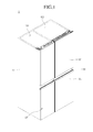
- Fig. 1 is a perspective view of a refrigerator according to an embodiment.
- Fig. 2 is a perspective view of the refrigerator with a first door opened according to an embodiment.
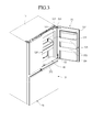
- Fig. 3 is a perspective view of the refrigerator with a second door opened according to an embodiment.
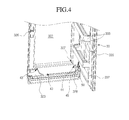
- Fig. 4 is an exploded perspective view illustrating a mounted structure of an auxiliary shelf according to an embodiment.
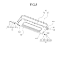
- Fig. 5 is an exploded perspective view of the auxiliary shelf.
- Fig. 6 is a front perspective view of a shelf guide according to an embodiment.
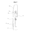
- Fig. 7 is a rear perspective view of the shelf guide.
- Fig. 8 is a view of a state in which the auxiliary shelf rotates.
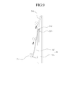
- Fig. 9 is a side view illustrating a state of the shelf guide when the auxiliary shelf is unfolded.
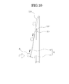
- Fig. 10 is a side view illustrating a state of the shelf guide when the auxiliary shelf is folded.
- Figs. 11 and 12 are side and perspective views of a state in which the auxiliary shelf and the shelf guide contact each other when a second door is closed.
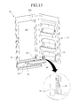
- Fig. 13 is a perspective view of a refrigerator with a second door opened according to another embodiment.
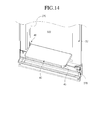
- Fig. 14 is a perspective view of a state in which an auxiliary shelf is unfolded according to another embodiment.
- Fig. 15 is an exploded perspective view illustrating a mounted structure of the auxiliary shelf.
- Fig. 1 is a perspective view of a refrigerator according to an embodiment
- Fig. 2 is a perspective view of the refrigerator with a first door opened according to an embodiment
- Fig. 3 is a perspective view of the refrigerator with a second door opened according to an embodiment.
- a refrigerator 1 may include a cabinet 10 defining a storage space and a door for opening or closing the storage space.
- an outer appearance of the refrigerator 1 may be defined by the cabinet 10 and the door.
- the inside of the cabinet 10 is horizontally partitioned by a mullion (not shown) to define a freezing compartment 101 and a refrigerating compartment 102.
- the door may include a freezing compartment door 20 for covering the freezing compartment 101 and a refrigerating compartment door 30 for covering the refrigerating compartment 102.
- an accommodation device 31 defining a separate space separated from the inside of the refrigerating compartment 102 may be disposed in the refrigerating compartment door 30.
- the inside of the refrigerating compartment 102 may be defined as a first storage compartment or a first storage region
- the inside of the accommodation device 31 may be defined as a second storage compartment 310 or a second storage region.
- the accommodation device 31 may have a structure in which a chamber is defined therein by a separate housing or cover or a structure constituted by only a square frame having an opening therein.
- a plurality of shelves or drawers may be vertically disposed in the opening.
- the plurality of shelves or drawers may be fixedly or detachably mounted on an inner circumferential surface of the frame.
- the plurality of shelves or drawers may be mounted slidable in front and rear directions on the inner circumferential surface of the frame.
- the refrigerating compartment door 30 may include a first door 32 for opening or closing the first storage compartment 102 and a second door 33 for opening or closing the second storage compartment 310.
- the first door 32 may have a top surface connected to that of the cabinet 10 through a door hinge 321 so that the door 32 is rotatably coupled to the cabinet 10 by the door hinge 321.
- a separate hinge (not shown) may be disposed on a lower end of the first door 32 so that the first door 32 is rotatably mounted.
- the first door 32 may be rotated to open or close the refrigerating compartment 102. That is, the first door 32 may be rotated to accommodate foods into the refrigerating compartment 102.
- a grip part 323 to be grasped by a user's hand to open the first door 32 may be horizontally disposed on a front surface corresponding to an approximately central portion of the first door 32.
- a grip part having the same shape as the grip part 323 may also be horizontally disposed on a front surface of the freezing compartment door 20. When the freezing compartment door 20 and the first door 32 are closed, the grip parts may be disposed on the same line.
- the grip part 323 may be recessed or stepped by a predetermined depth from the front surface of the first door 32.
- a stepped surface may be defined on an upper portion of the front surface of the first door 32, and an opening 322 may be defined in the stepped surface.
- a lower end of the stepped surface extends from an upper end of the grip part 323 to an upper end of the first door 32.
- the lower end of the stepped surface may have the same width as that of the first door 32.
- the stepped surface may forwardly protrude slightly from the grip part 323.
- the opening 322 may be defined in the stepped surface and have a size less than that of the stepped surface. Also, the accommodation device 31 may be disposed on a back surface of the first door 32 corresponding to a rear side of the opening 322. The accommodation device 31 may have an opened front surface. Thus, an access into the accommodation device 31 may be enabled through the opening 322.
- the second door 33 may be disposed on the stepped surface.
- the second door 33 may be rotatably coupled to the first door 32.
- the second door 33 may have the same size as that of the stepped surface.
- a lower end of the second door 33 may be placed on the same line as that of the upper end of the grip part 323 to define a spaced space through which the user hand is put into the grip part 323.
- a sealer 324 contacting a circumference of a front surface of the cabinet 10 when the first door 32 is closed is disposed on a circumference of the back surface of the first door 32.
- the sealer 324 may be formed of an elastically deformable material and thus be compressible.
- a magnet may be disposed within the sealer 324 so that the sealer 324 is closely attached to the cabinet 10.
- the opening 322 may be configured to withdraw foods accommodated within the accommodation device 31 in the state where the first door 32 is closed. Thus, the opening 322 may be opened in a state where the first door 32 covers the refrigerating compartment 102 to take the foods in or out of the accommodation device 31.
- the opening 322 may have a size corresponding to a front portion of the accommodation device 31.
- the opening 322 may be vertically defined over a position of the grip part 323 of the first door 32 and horizontally defined up to a region except for portions of both left and right ends of the first door 32.
- the opening 322 may correspond to the most upper region of the refrigerating compartment door 30. Therefore, the home bar according to the current embodiment may be significantly different in size and usability from a home bar used in a general refrigerator.
- the grip part 323 may be further recessed downward to allow the user to grasp the grip part 323 after the grip part 323 is recessed backward.
- the grip part 323 may be applied to the freezing compartment door 20 in the same shape as that of the refrigerating compartment door 30. When viewed from a front side, a left end and a right end of the grip part 323 may have the same height.
- the second door 33 is disposed on the refrigerating compartment door 30, when viewed from the front side, the refrigerating compartment door 30 and the freezing compartment door 20 may appear to be uniform.
- the second door 33 is configured to open or close the opening 322.
- the second door 33 is rotatably mounted on the first door 32 by an upper hinge 331. Both ends of the upper hinge 331 are coupled to a top surface of the first door 32 and a top surface of the second door 33, respectively.
- the upper hinge 331 has one end fixed to the top surface of the first door 32 and the other end through which a hinge shaft passes and is inserted into the top surface of the second door 33.
- the second door 33 may rotate with respect to the first door 32 by using the hinge shaft as a center.
- the hinge shaft serving as the rotation center of the first door 32 and the hinge shaft serving as the rotation center of the second door 33 may be provided as a single shaft or separate shafts.
- a lower hinge 328 may be further disposed on a lower end of the second door 33.
- the lower hinge 328 is inserted into the lower end of the second door 33 and supported by a lower hinge bracket fixed to a lower end of the stepped surface of the first door 32.
- the lower hinge 328 may have a cam structure or a spring structure so that the second door 33 is more smoothly opened or closed.
- first door 32 and the second door 33 may independently rotate with respect to each other.
- first door 32 and the second door 33 may be independently manipulated to selectively open or close the refrigerating compartment 102 and the opening 322.
- the hinge shafts serving as the rotation centers of the first and second doors 32 and 33 are provided as a single shaft or disposed adjacent to each other, the first and second doors 32 and 33 may be opened or closed by rotating in the same direction.
- the front surface of the second door 33 may be formed of the same material as those of the first door 32 and the freezing compartment door 20 to provide a continuous design or pattern. Also, the front surface of the second door 33 may be flush with that of the refrigerating compartment door 30 below the second door 33 in the state where the second door 33 is closed.
- the top surface and left and right surfaces of the second door 33 may be flush with those of the first door 32.
- the lower end of the second door 33 may extend up to a position corresponding to the region in which the grip part 323 of the refrigerating compartment door 30 is disposed. That is, the lower end of the second door 33 may extend up to a position corresponding to the stepped portion of the region in which the grip part 323 of the freezing compartment door 20 is disposed.
- the second door 33 may be integrated with the first door 32. When viewed from the front side, sense of unity may be provided so that connection portions on which the second door 33 is disposed are not seen.
- the front surfaces of the refrigerating compartment door 30 and the freezing compartment door 20 may have the same shape.
- a user which sees initially the refrigerator does not easily recognize the second door 33.
- the person may recognize the first and second doors 32 and 33 as one door.
- a protrusion 332 or slope protruding backwardly may be disposed on the back surface of the second door 33. A portion of the back surface of the second door 33 protrudes backward to define the protrusion 332. Also, the protrusion 332 protrudes in a shape corresponding to that of the opening 322. Thus, in the state where the second door 33 is closed, the protrusion 332 may be inserted into the opening 322 to primarily prevent cool air from leaking through the opening 322.
- An accommodation part 333 for accommodating foods is fixedly or detachably disposed on the protrusion 332.
- a separate basket may be attached to the accommodation part 333 to form a pocket shape.
- a gasket 334 is surrounded along an edge of the protrusion 332, i.e., a protrusion starting point of the protrusion 332.
- the gasket 334 may be formed of an elastically deformable material such as rubber or silicon.
- the gasket 334 When the second door 33 is closed, the gasket 334 may be closely attached to the stepped surface corresponding to the edge of the opening 322.
- the gasket 334 may be in a pressed state to secondarily prevent cool air within the accommodation device 31 from leaking.
- a door switch 325 for detecting an opening/closing of the second door 33 is disposed on a front surface of an upper end of the first door 32, i.e., an upper region of the stepped surface.
- the door switch 325 may be configured to output an alarm signal to the outside when the second door 33 is not closed.
- a locking unit is disposed on the front surface of the edge of the first door 32 corresponding to a side opposite to the rotation shaft of the second door 33 and the back surface of the edge of the second door 33.
- the locking unit may maintain the closed state of the second door 33.
- a restricted state of the locking unit may be selectively released by a pushing manipulation thereof to open the second door 33.
- the locking unit may have a structure equal to that of a general push switch.
- the locking unit includes a latch hook 335 disposed on the second door 33 and a latch slot 326 defined in a side of the first door corresponding to the latch hook 335 and in which the latch hook 335 is inserted. Also, the front surface of the second door 33 may be pushed in the closed state of the second door 33 to selectively restrict or release the latch hook 335 and the latch slot 326.
- An auxiliary shelf 40 may be further disposed on a lower end of the opening 322.
- the auxiliary shelf 40 may be rotatably mounted on the lower end of the opening 322.
- the auxiliary shelf 40 may be rotated and thus folded.
- the auxiliary shelf 40 may be rotated and thus unfolded.
- the auxiliary shelf 40 may have a horizontal length corresponding to a horizontal width of the opening 322.
- the auxiliary shelf 40 may have a vertical length which protrudes forwardly somewhat to pass through the opening 322, thereby placing foods thereon in the unfolded state thereof.
- Fig. 4 is an exploded perspective view illustrating a mounted structure of the auxiliary shelf according to an embodiment
- Fig. 5 is an exploded perspective view of the auxiliary shelf.
- the auxiliary shelf 40 includes an upper plate 41 defining an outer appearance of a top surface thereof and a lower plate 42 defining an outer appearance of a bottom surface thereof.
- a shelf hinge assembly 43, 44 is disposed on each of both sides of the auxiliary shelf 40.
- the shelf hinge assembly 43, 44 may be inserted into a hinge hole 327 defined in an inner surface of the opening 322 to allow the auxiliary shelf 40 to rotate.
- a guide roller 45 rolled in a state where the guide roller 45 contacts a shelf guide 50 that will be described later when the second door 33 is opened may be disposed on a side of the auxiliary shelf 40.
- the upper plate 41 may define the top surface of the auxiliary shelf 40 in the state where the auxiliary shelf 40 is unfolded.
- an edge portion of the upper plate 41 may have a bent plate shape.
- the upper plate 41 may have a complete plane shape to place products thereon.
- the lower plate 42 defines the bottom surface of the auxiliary shelf 40.
- the lower plate 42 has a shape corresponding to that of the upper plate 41.
- an edge of the lower plate 42 is bent upward and thus closely attached to the bent portion of the edge of the upper plate 41.
- a predetermined space may be defined between the lower plate 42 and the upper plate 41.
- the bent portion of the edge of the lower plate 42 may be disposed inside the bent portion of the edge of the upper plate 42.
- the space defined between the upper plate 41 and the lower plate 42 may have a height corresponding to a length of the bent portion of the edge of the upper plate 41.
- a shelf support part 421 protruding downward may be disposed on the lower plate 42.
- the shelf support part 42 may be contact with and hung on an edge of the lower end of the opening in the state where the auxiliary shelf 40 is unfolded.
- the auxiliary shelf 40 may be supported by the shelf support part 421 so that the auxiliary shelf 40 does not droop downward and is maintained in a horizontal state.
- a shelf groove 422 may be further defined in the bottom surface of a side surface of the lower plate 42 adjacent to the shelf guide 50.
- the shelf groove 422 may have a recessed shape to accommodate a portion of the shelf guide 50 in the state where the second door 33 is completely closed.
- a contact part 423 disposed on a lower end of the shelf groove 422 may be disposed at a position slightly higher than that of a lower end of a guide lever 52 or inclinedly disposed up to a position slightly higher than that of the lower end of the guide lever 52 in a state where the guide lever 52 of the shelf guide 50 protrudes.
- the contact part 423 of the shelf groove 422 and the lower end of the guide lever 52 contact each other while the second door 33 is closed. Also, the guide lever 52 may be pushed upward while being pressed by the contact part 423. Also, when the second door 33 is completely closed, the guide lever 52 may be fully inserted into a guide cover 51.
- the shelf hinge assembly 43, 44 is disposed in the space between the upper plate 41 and the lower plate 42. Also, since the hinge shaft 441 protrudes outside the shelf hinge assembly and then is inserted into the hinge hole 327, the auxiliary shelf 40 may be rotatably mounted on the opening 322.
- the shelf hinge assembly includes a sliding hinge 43 mounted on one side of left and right sides of the auxiliary shelf 40 and a damping hinge 44 mounted on the other side.
- the sliding hinge 43 is mounted on a left side of the auxiliary shelf 40. Also, the sliding hinge 43 is configured so that the hinge shaft 432 of the sliding hinge 43 is withdrawn or inserted through the hinge slot 424 defined in the lower plate 42.
- the sliding hinge 43 includes a hinge body 431 defining an outer appearance thereof, a hinge shaft 432 protruding outward from the inside of the hinge body 431, and a hinge spring 433 supporting the hinge shaft 432 inside the hinge body 431. Also, a portion of the hinge shaft 432 disposed within the hinge body 431 passes through a hole 431a defined in the hinge body 431 and thus is exposed to the outside. For this, the hinge spring 433 and the hinge shaft 432 are successively inserted into the hinge body 431, and then, the portion of the hinge shaft 432 is exposed to the outside through the hole 431a and the hinge slot 424.
- the hinge slot 424 and the hole 431a may be aligned with each other in the state where the hinge body 431 is assembled with the auxiliary shelf 40.
- the user inserts a rod-shaped tool, which has a thickness enough to be inserted into the hinge slot 424 and the hole 431a, into the hinge slot 424 and then slidably moves the hinge shaft 432.
- a protruding end of the hinge shaft 432 is inserted into the hinge body 431, and in this state, the auxiliary shelf 40 is inserted into the opening 322.
- the end of the hinge shaft 432 protrudes from the hinge body 431 and is inserted into the hinge hole 327.
- a process for separating the auxiliary shelf 40 may be the same as the above-described process. That is, the end of the hinge shaft 432 which is inserted into the hinge hole 327 by slidably moving the hinge shaft 432 is separated from the hinge hole 327, and then, the auxiliary shelf 40 is separated.
- the damping hinge 44 is mounted on a left side of the auxiliary shelf 40 to provide a rotation force to the auxiliary shelf 40.
- the auxiliary shelf 40 may be opened at a constant speed.
- the sliding hinge 43 and the damping hinge 44 may be exchanged in position. That is, the damping hinge 44 may be mounted on a right side of the auxiliary shelf 40, and the sliding hinge 43 may be mounted on the left side of the auxiliary shelf 40.
- the damping hinge 44 includes a hinge shaft 441, a fixed cam 442 connected to a side of the hinge shaft 441, and a movable cam 443 having a cam surface corresponding to the fixed cam 442 and supported by a damping spring 444.
- the damping spring 444 is fitted into an edge of a side opposite to the hinge shaft 441 and pressed or extended by an axial movement of the movable cam 443.
- the movable cam 443 may move only in the axial direction, but may not rotate together with the hinge shaft 441 so that the movable cam 442 is maintained in a fixed state.
- the fixed cap 443 may not move in the axial direction, but may rotate only together with the hinge shaft 441 in one body.
- the hinge shaft 441 and the fixed cam 442 rotate together with each other.
- the movable cam 443 contacting the cam surface of the fixed cam 442 moves in the axial direction of the hinge shaft 441 along the cam surface of the fixed cam 442.
- the movable cam 443 moves in a direction in which the damping spring 444 is pressed.
- the damping spring 444 may be maximally pressed by the movable cam 443.
- the movable cam 443 may push the fixed cam 442 by a restoring force of the damping spring 444.
- the fixed cam 442 rotates along the cam surface of the movable cam 443.
- the hinge shaft 441 may also rotate together with the fixed cam 442, and then the auxiliary shelf 40 may be unfolded while automatically rotating.
- the damping hinge 44 may be mounted in the space between the upper plate 41 and the lower plate 42. Alternatively, the damping hinge 44 may be mounted in the space between the upper plate 41 and the lower plate 42 in a state where the damping hinge 44 is accommodated in a separate case.
- the guide roller 45 may be mounted on a right edge of the front end of the auxiliary shelf 40.
- the guide roller 45 may be disposed at a position contacting the shelf guide 50 when the second door 33 is opened.
- the guide roller 45 may be rotatably mounted.
- a roller mounting part 425 may be recessed in the edge of the auxiliary shelf 40, and a bracket 451 may be mounted on the roller mounting part 425.
- the bracket 451 may be configured to rotatably fix the guide roller 45 to the auxiliary shelf 40.
- the shelf guide 50 is disposed on the back surface of the second door 33.
- the shelf guide 50 may contact the auxiliary shelf 40 to open or close the auxiliary shelf 40 when the second door 33 is opened or closed.
- the shelf guide 50 may be disposed on a lower portion of the second door 33 which contacts the guide roller 45 when the second door 33 is opened or closed.
- shelf guide 50 will be described in detail with reference to the accompanying drawings.
- Fig. 6 is a front perspective view of a shelf guide according to an embodiment
- Fig. 7 is a rear perspective view of the shelf guide.
- the shelf guide 50 is disposed on the back surface of the second door 33.
- the shelf guide 50 includes a guide cover 51 defining an outer appearance thereof, a guide lever 52 rotatably shaft-coupled to the guide cover 51, and a lever spring 53 elastically supporting the guide lever 52.
- a cover opening 511 for mounting the guide lever 52 is defined in the guide cover 51.
- the cover opening 511 has a shape corresponding to that of the guide lever 52.
- the cover opening 511 passes through the guide cover 51 in front and rear directions and is defined in a front surface of the guide cover 51.
- a recess part recessed from the front surface of the guide cover 51 may be defined instead of the cover opening 511.
- a side hole 512 is defined in each of left and right surfaces of the guide cover 51.
- a lever shaft 521 serving as a rotation shaft of the guide lever 52 is inserted into the side hole 512.
- the side hole 512 may vertically extend by a predetermined length.
- the guide lever 52 may be rotatably and vertically movably coupled to the guide cover 51.
- an inclined surface 513 inclined at a predetermined angle is disposed from an upper portion of the cover opening 511 up to an upper end of the guide cover 51.
- the guide lever 52 may have a length corresponding to that of the cover opening 511 so that the guide lever 52 is inserted into the guide cover 51.
- the guide lever 52 contacting the guide roller 45 may have a flat front surface.
- the guide roller 45 may have a circumferential surface bent backward and having a predetermined thickness.
- an upper end of the guide lever 52 may have a width less than that of a lower end thereof to prevent the guide lever 52 from interfering with an edge of the cover opening 511 when the guide lever 52 is inserted into the cover opening 511 while rotating.
- a lever shaft 521 is disposed on an upper end of the guide lever 52.
- the lever shaft 521 may serve as a rotation center of the guide lever 52.
- the lever shaft 521 extends in a direction passing through left and right surfaces of the guide lever 52 and then is penetratedly inserted into the side hole 512.
- the lever shaft 521 may be integrated with the guide lever 52. Alternatively, the lever shaft 521 may be coupled to the guide lever 52 as a separate part.
- a lever spring 53 may be disposed at a position spaced a predetermined distance downward from a back surface of the guide lever 52, i.e., the lever shaft 521.
- the lever spring 53 may support the guide lever 52 from a rear side. Also, when an external force is not applied to the guide lever 52, the lever spring 53 may push the guide lever in a front direction.
- a lower end of the guide lever 52 may protrude from the front surface of the guide cover 51 by an elastic force of the lever spring 53.
- the lever shaft 521 may be disposed on a lower end of the guide hole 512 by a self-weight of the guide lever 52.
- Fig. 8 is a perspective view of a state in which the auxiliary shelf is opened to rotate at a predetermined angle.
- the auxiliary shelf 40 when the second door 33 is closed, the auxiliary shelf 40 may be closely attached to the back surface of the second door 33 in the state where the auxiliary shelf 40 is folded.
- the auxiliary shelf 40 may be vertically folded.
- the bottom surface of the auxiliary shelf 40, i.e., the lower plate 42 may face a front side.
- the auxiliary shelf 40 does not move even though the first door 32 rotates in the state where the auxiliary shelf 40 contacts the second door 33.
- the user may push the front surface of the second door 33 to release the restriction of the latch hook 335, thereby opening the second door 33.
- the second door 33 rotates using the upper hinge 321 and the lower hinge 328 as shafts. Also, while the second door 33 is opened, the auxiliary shelf 40 rotates by the damping hinge 44 as shown in Fig. 8 . Also, in the state where the second door 33 is fully opened, the auxiliary shelf 40 may be fully unfolded as shown in Fig. 3 . Thus, the auxiliary shelf 40 may be maintained in a completely horizontal state by the shelf support part 421.
- the user may withdraw foods accommodated in the storage space within the opening 322 and place beverages or cups on the auxiliary shelf 40.
- the second door 33 When the foods are completely withdrawn through the opening 322, the second door 33 is closed. When the second door 33 is closed at an angle greater than a preset angle, the shelf guide 50 and the guide roller 45 contact each other.
- the guide roller 45 may contact the lower end of the guide lever 52. Also, when the second door 33 further rotates and is closed, the guide roller 45 may move along the front surface of the guide lever 52. Then, the auxiliary shelf 40 may smoothly rotate and be gradually closed.
- the guide lever 52 may be disposed inside the guide cover 51 and in the shelf groove 422 of the auxiliary shelf 40.
- Fig. 9 is a side view illustrating a state of the shelf guide when the auxiliary shelf is unfolded
- Fig. 10 is a side view illustrating a state of the shelf guide when the auxiliary shelf is folded
- Figs. 11 and 12 are side and perspective views of a state in which the auxiliary shelf and the shelf guide contact each other when a second door is closed.
- the guide roller 45 of the auxiliary shelf 40 may firstly contact the inclined surface 513 of the guide cover 51. Then, the guide roller 45 moves along the inclined surface 513. Here, the guide roller 45 may move downward from a top surface of the guide lever 52.
- the guide roller 45 moves along the shelf guide 50 as shown in Fig. 9 .
- the auxiliary shelf 40 may also be smoothly unfolded according to the opening speed of the second door 33.
- the auxiliary shelf 40 may not contact the shelf guide 50 and also be rotated and unfolded at a predetermined speed by the rotation force provided from the damping hinge 44.
- the second door 33 When the second door 33 is closed in the state where the auxiliary shelf 40 is fully unfolded, the second door 33 may rotate at a preset angle as shown in Fig. 10 , and then, the guide roller 45 firstly contacts the lower end of the guide lever 52.
- the lever shaft 521 of the guide lever 52 may be disposed on the lower end of the side hole 512, and the back surface of the lower end of the guide lever 52 may be hung on the front surface of the guide cover 51 corresponding to the lower end of the cover opening 511 to protrude.
- the guide roller 45 ascends along the front surface of the guide lever 52.
- the guide roller 45 may move upward along the inclined surface 513 of the guide cover 51, the auxiliary shelf 40 may be folded.
- the second door 33 When the second door 33 further rotates and is closed in the state where the guide roller 45 moves up to the upper end of the shelf guide 50, as shown in Fig. 11 , the lower end of the guide lever 52 contacts the lower end of the shelf groove 422 defined in the bottom surface of the auxiliary shelf 40.
- the contact part 423 disposed in the shelf groove 422 presses the lower end of the guide lever 52 in a direction in which the guide lever 52 is pushed upward from a lower side.
- the pressing force may be inclinedly applied to the guide lever 52 in a direction between a 12 o'clock direction and a 3 o'clock direction.
- the guide lever 52 may be pressed while being pushed upward to ascend.
- the lever shaft 521 of the guide lever 52 may move to the upper end of the side hole 512.
- the guide lever 52 rotates with respect to a center of the lever shaft 521 and then is inserted into the cover opening 511 as shown in Fig. 12 .
- the front surface of the guide lever 52 slightly protruding from the front surface of the guide cover 51 may be disposed within the shelf groove 422.
- the lower end of the guide lever 52 may be disposed at a position higher than that of the cover opening 511.
- Embodiments different from the foregoing embodiment may be applied to the refrigerator according to the present disclosure.
- a refrigerator according to another embodiment is characterized in that an auxiliary shelf 40 is rotatably mounted in an opening 322 by a separate shelf bracket disposed in the opening 322.
- the refrigerator according to another embodiment is equal to the refrigerator according to the foregoing embodiment except for the shelf bracket and a shelf guide. Detailed descriptions with respect to the same constitution will be omitted to prevent the duplicated description, and also, the same constitution will be denoted by the same reference numeral.
- Fig. 13 is a perspective view of a refrigerator with a second door opened according to another embodiment
- Fig. 14 is a perspective view of a state in which an auxiliary shelf is unfolded according to another embodiment
- Fig. 15 is an exploded perspective view illustrating a mounted structure of the auxiliary shelf.
- a refrigerator door 30 includes a first door 32 and a second door 33. Also, an opening 322 may be defined in the first door 32, and the second door 33 may rotate to open or close the opening 322.
- an auxiliary shelf 40 interlocked with the opening of the second door 33 may be disposed in the opening 322.
- Two upper and lower plate-shaped members may be coupled to each other to constitute the auxiliary shelf 40.
- the auxiliary shelf 40 may be provided as one plate-shaped member.
- a sliding hinge 43 and a damping hinge 44 may be disposed on rear ends of both left and right surfaces of the auxiliary shelf 40, respectively.
- the sliding hinge 43 may slidably move a hinge shaft 432 by an external manipulation to allow the auxiliary shelf 40 to be easily attached or detached.
- the damping hinge 44 may provide a force for unfolding the auxiliary shelf 40 when the second door 33 is opened in a state where the auxiliary shelf 40 is folded.
- a guide roller 45 is disposed on an edge of the auxiliary shelf 40.
- the guide roller 45 may contact a shelf guide 60 disposed on a back surface of the second door 33 to allow the auxiliary shelf 40 to smoothly rotate.
- An opening frame 329 may be mounted on the opening 322.
- the opening frame 329 is mounted on each of both side surfaces of the opening 322.
- a shelf bracket 46 connecting the auxiliary shelf 40 is mounted on the opening 322.
- the shelf bracket 46 is configured to allow the auxiliary shelf 40 to be mounted on the opening 322.
- the shelf bracket 46 may have one side on which hinge shafts 432 and 441 of the auxiliary shelf 40 are mounted and the other side mounted on the opening frame 329.
- the shelf bracket 46 includes a bracket mounting part 461 fixed to the opening frame 329 and a hinge mounting part 463 having a hinge hole 464 in which each of the hinge shafts 432 and 441 is inserted.
- a screw hole 462 in which a screw is inserted is defined in the bracket mounting part 461.
- the hinge mounting part 463 extends forward from the bracket mounting part 461.
- the hinge mounting part 463 may extend forward by a predetermined distance to decide positions of the hinge shafts 432 and 441.
- a bush formed of an engineering plastic material to allow the hinge shaft 464 to smoothly rotate may be further mounted on the inside of the hinge hole 464.
- the positions of the hinge shafts 432 and 441 of the auxiliary shelf 40 may be decided by the shelf bracket 46.
- the hinge mounting part 463 may be adjusted in length to locate the auxiliary shelf 40 on a rear side of the second door 33 by a sufficient distance so that the auxiliary shelf 40 does not interfere with the back surface of the second door 33 when the second door is fully closed.
- the shelf guide 60 is mounted on the back surface of the second door 33 corresponding to a position of the guide roller 45.
- the shelf guide 60 is disposed on the back surface of the second door 33.
- the shelf guide 60 may further protrude toward a lower side thereof from an upper side thereof.
- the shelf guide 60 may have an inclined surface 61 contacting the guide roller 45.
- the shelf guide 60 may be integrally molded with a door linear defining the back surface of the second door 33 or a portion of the second door 33. Alternatively, the shelf guide 60 may be molded as a separate member and then mounted on the second door 33.
- the guide roller 45 contacts a lower end of the shelf guide 60, i.e., a lower end of the inclined surface 61. Also, when the second door 33 is further closed, the guide roller 45 may move upward along the inclined surface 61. Also, when the second door 33 is fully closed, the auxiliary shelf 40 may be vertically folded.
- the auxiliary shelf 400 may be disposed on a position spaced backward by a sufficient distance to prevent the auxiliary shelf 40 from interfering with the shelf guide 60.
- the shelf bracket 46 may be disposed so that the hinge shafts 432 and 441 of the auxiliary shelf 40 are disposed on positions nearer to a rear end of the opening 322 than a front end of the opening 322.
- the auxiliary shelf may be unfolded by being interlocked with the open of the second door.
- the user may place foods to be accommodated into or withdrawn from the accommodation device on the unfolded auxiliary shelf to easily realize the accommodation/withdrawal of the foods.
- the shelf guide attached to the back surface of the door may provide the inclined surface in the state where the shelf guide protrudes when contacting the guide roller of the auxiliary shelf to allow the auxiliary shelf to smoothly rotate.
- the protrusion portion of the shelf guide may be inserted to minimize a space between the back surface of the auxiliary shelf and the second door in the state where the second door is closed.
- the embodiments may provide a structure which smoothly guides the rotation of the auxiliary shelf in a narrow space between the back surface of the auxiliary shelf and the second door when the auxiliary shelf rotates and prevents the auxiliary shelf from interfering with the second door when the second door is closed after the auxiliary shelf fully rotates.
- the hinge bracket on which the auxiliary shelf is mounted may be disposed on the first door. Thus, it may be unnecessary to directly process a hole for accommodating the rotation shaft of the auxiliary shelf. Also, the auxiliary shelf may be rotatably disposed on the first door by the hinge bracket.
- the auxiliary shelf may be disposed more away from the back surface of the second door regardless of the width of the opening to secure a space between the auxiliary shelf and the second door in the state where the second door is closed.
- the shelf guide disposed on the second door may protrude with sufficient inclination and height to prevent the shelf guide from interfering with the second door when the second door is closed.
Landscapes
- Engineering & Computer Science (AREA)
- Chemical & Material Sciences (AREA)
- Combustion & Propulsion (AREA)
- Physics & Mathematics (AREA)
- Mechanical Engineering (AREA)
- Thermal Sciences (AREA)
- General Engineering & Computer Science (AREA)
- Refrigerator Housings (AREA)
Applications Claiming Priority (1)
| Application Number | Priority Date | Filing Date | Title |
|---|---|---|---|
| KR1020120066866A KR101918296B1 (ko) | 2012-06-21 | 2012-06-21 | 냉장고 |
Publications (3)
| Publication Number | Publication Date |
|---|---|
| EP2677258A2 true EP2677258A2 (de) | 2013-12-25 |
| EP2677258A3 EP2677258A3 (de) | 2014-07-23 |
| EP2677258B1 EP2677258B1 (de) | 2019-08-07 |
Family
ID=48703159
Family Applications (1)
| Application Number | Title | Priority Date | Filing Date |
|---|---|---|---|
| EP13173000.4A Active EP2677258B1 (de) | 2012-06-21 | 2013-06-20 | Kühlschrank |
Country Status (4)
| Country | Link |
|---|---|
| US (1) | US8960826B2 (de) |
| EP (1) | EP2677258B1 (de) |
| KR (1) | KR101918296B1 (de) |
| CN (1) | CN103512308B (de) |
Cited By (5)
| Publication number | Priority date | Publication date | Assignee | Title |
|---|---|---|---|---|
| WO2015149832A1 (en) * | 2014-03-31 | 2015-10-08 | Arcelik Anonim Sirketi | Improved hinge assembly for flap door in refrigeration appliance |
| EP3070421A1 (de) * | 2015-03-18 | 2016-09-21 | LG Electronics Inc. | Kühlschrank |
| US20170350637A1 (en) * | 2016-06-07 | 2017-12-07 | Lg Electronics Inc. | Refrigerator and folding guide device provided therein |
| CN112797701A (zh) * | 2019-11-13 | 2021-05-14 | 东芝生活电器株式会社 | 冰箱 |
| CN114688817A (zh) * | 2020-12-31 | 2022-07-01 | 青岛海尔电冰箱有限公司 | 用于冰箱的自动开关门装置以及具有其的冰箱 |
Families Citing this family (27)
| Publication number | Priority date | Publication date | Assignee | Title |
|---|---|---|---|---|
| KR101844072B1 (ko) * | 2011-11-11 | 2018-05-15 | 엘지전자 주식회사 | 냉장고 |
| KR102100192B1 (ko) * | 2013-09-13 | 2020-04-13 | 엘지전자 주식회사 | 냉장고 |
| KR102228916B1 (ko) * | 2014-03-11 | 2021-03-17 | 삼성전자주식회사 | 냉장고 |
| KR101691260B1 (ko) | 2014-10-17 | 2016-12-29 | 엘지전자 주식회사 | 냉장고 |
| US9593879B2 (en) | 2015-03-17 | 2017-03-14 | Whirlpool Corporation | U-shaped tuck shelf |
| USD810795S1 (en) | 2015-03-17 | 2018-02-20 | Whirlpool Corporation | Refrigerator |
| KR102098689B1 (ko) * | 2015-07-08 | 2020-04-08 | 삼성전자주식회사 | 냉장고 |
| USD808446S1 (en) | 2015-10-09 | 2018-01-23 | Whirlpool Corporation | Refrigerator shelf |
| KR102386700B1 (ko) * | 2015-11-04 | 2022-04-14 | 엘지전자 주식회사 | 냉장고 |
| CN112524874B (zh) | 2015-11-04 | 2022-12-30 | Lg 电子株式会社 | 冰箱 |
| KR102447530B1 (ko) * | 2016-04-15 | 2022-09-26 | 엘지전자 주식회사 | 냉장고 |
| CN106014120A (zh) * | 2016-07-07 | 2016-10-12 | 黄为 | 弹性冰箱折叠门 |
| US10281197B2 (en) | 2016-10-11 | 2019-05-07 | Whirlpool Corporation | Quick shelf adjustment mechanism for a refrigerating appliance |
| BR102017009967B1 (pt) | 2017-05-11 | 2024-02-20 | Whirlpool S.A. | Equipamento eletrodoméstico compreendendo arranjo de prateleira |
| US10655905B2 (en) | 2017-06-13 | 2020-05-19 | Whirlpool Corporation | Flexible compartment for a refrigerator |
| US10677514B2 (en) | 2017-08-01 | 2020-06-09 | Whirlpool Corporation | Door bin with dual material and system lock |
| US10823480B2 (en) | 2017-08-01 | 2020-11-03 | Whirlpool Corporation | Air flow mechanism for compartment |
| BR102017019233B1 (pt) | 2017-09-08 | 2022-10-18 | Whirlpool S.A. | Sistema de translação para prateleira de refrigerador |
| US10823490B2 (en) | 2017-10-12 | 2020-11-03 | Whirlpool Corporation | Shelf assembly for appliance |
| US10371436B2 (en) | 2017-11-08 | 2019-08-06 | Whirlpool Corporation | Bin assembly |
| US10808944B2 (en) | 2018-01-12 | 2020-10-20 | Whirlpool Corporation | Swinging rack |
| US10551071B2 (en) | 2018-05-11 | 2020-02-04 | Whirlpool Corporation | Oven rack system with removable support elements |
| US11073329B2 (en) | 2018-10-31 | 2021-07-27 | Whirlpool Corporation | Refrigerator shelving frame with snap-in sliding insert |
| KR102903378B1 (ko) * | 2019-09-17 | 2025-12-24 | 엘지전자 주식회사 | 냉장고 |
| KR20210106270A (ko) | 2020-02-20 | 2021-08-30 | 삼성전자주식회사 | 냉장고 |
| CN114001519B (zh) * | 2021-12-01 | 2024-01-30 | 珠海格力电器股份有限公司 | 收纳盒和冰箱 |
| CN116817521B (zh) * | 2023-05-29 | 2025-07-25 | 海信冰箱有限公司 | 冰箱 |
Family Cites Families (23)
| Publication number | Priority date | Publication date | Assignee | Title |
|---|---|---|---|---|
| US1479721A (en) * | 1923-08-09 | 1924-01-01 | Liedtke Horst | Medical service cabinet |
| US2920914A (en) * | 1956-10-29 | 1960-01-12 | William P Jenkins | Dead-locking jamb bolt |
| US3212835A (en) * | 1962-01-16 | 1965-10-19 | Whirlpool Co | Drop down cabinet door and associated removable receptacle |
| KR100203985B1 (ko) * | 1995-07-20 | 1999-06-15 | 전주범 | 냉장고의 회동선반 |
| KR0136407B1 (ko) * | 1995-08-04 | 1998-07-01 | 배순훈 | 냉장고 포켓구조 |
| KR0179603B1 (ko) * | 1996-10-21 | 1999-04-15 | 대우전자주식회사 | 착탈이 용이하도록 롤러가 장착된 냉장고의 선반 |
| US6484529B2 (en) * | 2000-04-19 | 2002-11-26 | Whirlpool Corporation | Cabinet construction for an ice maker or other refrigeration appliance |
| JP4243163B2 (ja) * | 2003-10-21 | 2009-03-25 | 三洋電機株式会社 | 低温貯蔵庫 |
| US7430111B2 (en) * | 2005-01-04 | 2008-09-30 | Lg Electronics Inc. | Mounting structure for display unit in refrigerator |
| US20060226750A1 (en) * | 2005-04-08 | 2006-10-12 | Lee Jeong Y | Refrigerator having home bar |
| KR100720368B1 (ko) * | 2005-09-02 | 2007-05-21 | 채권병 | 냉장고용 홈바도어 |
| US8640482B2 (en) * | 2006-08-11 | 2014-02-04 | Samsung Electronics Co., Ltd. | Refrigerator having folding shelf |
| KR101263433B1 (ko) * | 2006-09-19 | 2013-05-10 | 삼성전자주식회사 | 냉장고 및 냉장고의 도어 열림장치 |
| KR20080086775A (ko) * | 2007-03-23 | 2008-09-26 | 장명택 | 다중기능 힌지장치 |
| US8726689B2 (en) * | 2008-05-06 | 2014-05-20 | Samsung Electronics Co., Ltd. | Refrigerator with cold storage unit |
| KR101602215B1 (ko) * | 2009-05-08 | 2016-03-21 | 엘지전자 주식회사 | 냉장고의 수납 장치 및 이를 구비한 냉장고 |
| KR101307681B1 (ko) * | 2009-06-03 | 2013-09-12 | 엘지전자 주식회사 | 냉장고 |
| DE102009027887A1 (de) * | 2009-07-21 | 2011-01-27 | BSH Bosch und Siemens Hausgeräte GmbH | Höhenverstellbarer Kühlgutträger |
| KR101319231B1 (ko) * | 2009-08-20 | 2013-10-16 | 스가쓰네 고우교 가부시키가이샤 | 문 개폐 시스템 및 문 개폐 시스템용 캐치 |
| CN102116554A (zh) * | 2010-01-04 | 2011-07-06 | Lg电子株式会社 | 电冰箱 |
| KR101704817B1 (ko) * | 2010-08-20 | 2017-02-08 | 엘지전자 주식회사 | 냉장고 |
| KR101923471B1 (ko) * | 2011-10-04 | 2018-11-29 | 엘지전자 주식회사 | 냉장고 |
| KR101844072B1 (ko) * | 2011-11-11 | 2018-05-15 | 엘지전자 주식회사 | 냉장고 |
-
2012
- 2012-06-21 KR KR1020120066866A patent/KR101918296B1/ko not_active Expired - Fee Related
-
2013
- 2013-06-20 EP EP13173000.4A patent/EP2677258B1/de active Active
- 2013-06-21 US US13/923,606 patent/US8960826B2/en not_active Expired - Fee Related
- 2013-06-21 CN CN201310250305.3A patent/CN103512308B/zh not_active Expired - Fee Related
Cited By (9)
| Publication number | Priority date | Publication date | Assignee | Title |
|---|---|---|---|---|
| WO2015149832A1 (en) * | 2014-03-31 | 2015-10-08 | Arcelik Anonim Sirketi | Improved hinge assembly for flap door in refrigeration appliance |
| EP3070421A1 (de) * | 2015-03-18 | 2016-09-21 | LG Electronics Inc. | Kühlschrank |
| US9879901B2 (en) | 2015-03-18 | 2018-01-30 | Lg Electronics Inc. | Refrigerator |
| EP3543632A1 (de) * | 2015-03-18 | 2019-09-25 | LG Electronics Inc. | Kühlschrank |
| US20170350637A1 (en) * | 2016-06-07 | 2017-12-07 | Lg Electronics Inc. | Refrigerator and folding guide device provided therein |
| US10539359B2 (en) * | 2016-06-07 | 2020-01-21 | Lg Electronics Inc. | Refrigerator and folding guide device provided therein |
| CN112797701A (zh) * | 2019-11-13 | 2021-05-14 | 东芝生活电器株式会社 | 冰箱 |
| CN114688817A (zh) * | 2020-12-31 | 2022-07-01 | 青岛海尔电冰箱有限公司 | 用于冰箱的自动开关门装置以及具有其的冰箱 |
| CN114688817B (zh) * | 2020-12-31 | 2023-03-17 | 青岛海尔电冰箱有限公司 | 用于冰箱的自动开关门装置以及具有其的冰箱 |
Also Published As
| Publication number | Publication date |
|---|---|
| KR20130143367A (ko) | 2013-12-31 |
| CN103512308B (zh) | 2015-09-30 |
| CN103512308A (zh) | 2014-01-15 |
| EP2677258A3 (de) | 2014-07-23 |
| KR101918296B1 (ko) | 2019-01-29 |
| US20130342095A1 (en) | 2013-12-26 |
| US8960826B2 (en) | 2015-02-24 |
| EP2677258B1 (de) | 2019-08-07 |
Similar Documents
| Publication | Publication Date | Title |
|---|---|---|
| EP2677258B1 (de) | Kühlschrank | |
| EP3546862B1 (de) | Kühlschrank | |
| EP3674640B1 (de) | Kühlschrank | |
| EP2594874B1 (de) | Kühlschrank | |
| US9759477B2 (en) | Refrigerator | |
| EP3617630B1 (de) | Kühlschrank | |
| US10939758B2 (en) | Refrigerator | |
| KR102026464B1 (ko) | 가변선반장치 및 이를 포함한 냉장고 | |
| EP2789944B1 (de) | Kühlschrank | |
| KR102186243B1 (ko) | 냉장고 | |
| EP2792978B1 (de) | Lebensmittelbehälter | |
| EP3534096B1 (de) | Kühlschrank mit einem korb, der an einer tür durch einen rahmen befestigt ist | |
| EP3040663B1 (de) | Kühlschrank | |
| KR20140109035A (ko) | 냉장고 | |
| AU2019283768B2 (en) | Refrigerator | |
| US10900708B2 (en) | Refrigerator | |
| KR101869556B1 (ko) | 냉장고 | |
| KR200463488Y1 (ko) | 냉장고 | |
| KR101956034B1 (ko) | 저장용기를 구비하는 냉장고 | |
| KR20140103501A (ko) | 냉장고 |
Legal Events
| Date | Code | Title | Description |
|---|---|---|---|
| PUAI | Public reference made under article 153(3) epc to a published international application that has entered the european phase |
Free format text: ORIGINAL CODE: 0009012 |
|
| AK | Designated contracting states |
Kind code of ref document: A2 Designated state(s): AL AT BE BG CH CY CZ DE DK EE ES FI FR GB GR HR HU IE IS IT LI LT LU LV MC MK MT NL NO PL PT RO RS SE SI SK SM TR |
|
| AX | Request for extension of the european patent |
Extension state: BA ME |
|
| PUAL | Search report despatched |
Free format text: ORIGINAL CODE: 0009013 |
|
| AK | Designated contracting states |
Kind code of ref document: A3 Designated state(s): AL AT BE BG CH CY CZ DE DK EE ES FI FR GB GR HR HU IE IS IT LI LT LU LV MC MK MT NL NO PL PT RO RS SE SI SK SM TR |
|
| AX | Request for extension of the european patent |
Extension state: BA ME |
|
| RIC1 | Information provided on ipc code assigned before grant |
Ipc: F25D 23/04 20060101ALI20140613BHEP Ipc: F25D 25/02 20060101AFI20140613BHEP |
|
| 17P | Request for examination filed |
Effective date: 20150105 |
|
| RBV | Designated contracting states (corrected) |
Designated state(s): AL AT BE BG CH CY CZ DE DK EE ES FI FR GB GR HR HU IE IS IT LI LT LU LV MC MK MT NL NO PL PT RO RS SE SI SK SM TR |
|
| RIC1 | Information provided on ipc code assigned before grant |
Ipc: F25D 23/04 20060101ALI20180817BHEP Ipc: F25D 25/02 20060101AFI20180817BHEP Ipc: F25D 23/02 20060101ALI20180817BHEP |
|
| GRAP | Despatch of communication of intention to grant a patent |
Free format text: ORIGINAL CODE: EPIDOSNIGR1 |
|
| STAA | Information on the status of an ep patent application or granted ep patent |
Free format text: STATUS: GRANT OF PATENT IS INTENDED |
|
| INTG | Intention to grant announced |
Effective date: 20190304 |
|
| RAP1 | Party data changed (applicant data changed or rights of an application transferred) |
Owner name: LG ELECTRONICS INC. |
|
| GRAS | Grant fee paid |
Free format text: ORIGINAL CODE: EPIDOSNIGR3 |
|
| GRAA | (expected) grant |
Free format text: ORIGINAL CODE: 0009210 |
|
| STAA | Information on the status of an ep patent application or granted ep patent |
Free format text: STATUS: THE PATENT HAS BEEN GRANTED |
|
| AK | Designated contracting states |
Kind code of ref document: B1 Designated state(s): AL AT BE BG CH CY CZ DE DK EE ES FI FR GB GR HR HU IE IS IT LI LT LU LV MC MK MT NL NO PL PT RO RS SE SI SK SM TR |
|
| REG | Reference to a national code |
Ref country code: GB Ref legal event code: FG4D |
|
| REG | Reference to a national code |
Ref country code: CH Ref legal event code: EP Ref country code: AT Ref legal event code: REF Ref document number: 1164516 Country of ref document: AT Kind code of ref document: T Effective date: 20190815 |
|
| REG | Reference to a national code |
Ref country code: DE Ref legal event code: R096 Ref document number: 602013058701 Country of ref document: DE |
|
| REG | Reference to a national code |
Ref country code: IE Ref legal event code: FG4D |
|
| REG | Reference to a national code |
Ref country code: NL Ref legal event code: MP Effective date: 20190807 |
|
| REG | Reference to a national code |
Ref country code: LT Ref legal event code: MG4D |
|
| PG25 | Lapsed in a contracting state [announced via postgrant information from national office to epo] |
Ref country code: NO Free format text: LAPSE BECAUSE OF FAILURE TO SUBMIT A TRANSLATION OF THE DESCRIPTION OR TO PAY THE FEE WITHIN THE PRESCRIBED TIME-LIMIT Effective date: 20191107 Ref country code: FI Free format text: LAPSE BECAUSE OF FAILURE TO SUBMIT A TRANSLATION OF THE DESCRIPTION OR TO PAY THE FEE WITHIN THE PRESCRIBED TIME-LIMIT Effective date: 20190807 Ref country code: SE Free format text: LAPSE BECAUSE OF FAILURE TO SUBMIT A TRANSLATION OF THE DESCRIPTION OR TO PAY THE FEE WITHIN THE PRESCRIBED TIME-LIMIT Effective date: 20190807 Ref country code: HR Free format text: LAPSE BECAUSE OF FAILURE TO SUBMIT A TRANSLATION OF THE DESCRIPTION OR TO PAY THE FEE WITHIN THE PRESCRIBED TIME-LIMIT Effective date: 20190807 Ref country code: BG Free format text: LAPSE BECAUSE OF FAILURE TO SUBMIT A TRANSLATION OF THE DESCRIPTION OR TO PAY THE FEE WITHIN THE PRESCRIBED TIME-LIMIT Effective date: 20191107 Ref country code: NL Free format text: LAPSE BECAUSE OF FAILURE TO SUBMIT A TRANSLATION OF THE DESCRIPTION OR TO PAY THE FEE WITHIN THE PRESCRIBED TIME-LIMIT Effective date: 20190807 Ref country code: PT Free format text: LAPSE BECAUSE OF FAILURE TO SUBMIT A TRANSLATION OF THE DESCRIPTION OR TO PAY THE FEE WITHIN THE PRESCRIBED TIME-LIMIT Effective date: 20191209 Ref country code: LT Free format text: LAPSE BECAUSE OF FAILURE TO SUBMIT A TRANSLATION OF THE DESCRIPTION OR TO PAY THE FEE WITHIN THE PRESCRIBED TIME-LIMIT Effective date: 20190807 |
|
| REG | Reference to a national code |
Ref country code: AT Ref legal event code: MK05 Ref document number: 1164516 Country of ref document: AT Kind code of ref document: T Effective date: 20190807 |
|
| PG25 | Lapsed in a contracting state [announced via postgrant information from national office to epo] |
Ref country code: AL Free format text: LAPSE BECAUSE OF FAILURE TO SUBMIT A TRANSLATION OF THE DESCRIPTION OR TO PAY THE FEE WITHIN THE PRESCRIBED TIME-LIMIT Effective date: 20190807 Ref country code: LV Free format text: LAPSE BECAUSE OF FAILURE TO SUBMIT A TRANSLATION OF THE DESCRIPTION OR TO PAY THE FEE WITHIN THE PRESCRIBED TIME-LIMIT Effective date: 20190807 Ref country code: IS Free format text: LAPSE BECAUSE OF FAILURE TO SUBMIT A TRANSLATION OF THE DESCRIPTION OR TO PAY THE FEE WITHIN THE PRESCRIBED TIME-LIMIT Effective date: 20191207 Ref country code: RS Free format text: LAPSE BECAUSE OF FAILURE TO SUBMIT A TRANSLATION OF THE DESCRIPTION OR TO PAY THE FEE WITHIN THE PRESCRIBED TIME-LIMIT Effective date: 20190807 Ref country code: GR Free format text: LAPSE BECAUSE OF FAILURE TO SUBMIT A TRANSLATION OF THE DESCRIPTION OR TO PAY THE FEE WITHIN THE PRESCRIBED TIME-LIMIT Effective date: 20191108 Ref country code: ES Free format text: LAPSE BECAUSE OF FAILURE TO SUBMIT A TRANSLATION OF THE DESCRIPTION OR TO PAY THE FEE WITHIN THE PRESCRIBED TIME-LIMIT Effective date: 20190807 |
|
| PG25 | Lapsed in a contracting state [announced via postgrant information from national office to epo] |
Ref country code: TR Free format text: LAPSE BECAUSE OF FAILURE TO SUBMIT A TRANSLATION OF THE DESCRIPTION OR TO PAY THE FEE WITHIN THE PRESCRIBED TIME-LIMIT Effective date: 20190807 |
|
| PG25 | Lapsed in a contracting state [announced via postgrant information from national office to epo] |
Ref country code: RO Free format text: LAPSE BECAUSE OF FAILURE TO SUBMIT A TRANSLATION OF THE DESCRIPTION OR TO PAY THE FEE WITHIN THE PRESCRIBED TIME-LIMIT Effective date: 20190807 Ref country code: PL Free format text: LAPSE BECAUSE OF FAILURE TO SUBMIT A TRANSLATION OF THE DESCRIPTION OR TO PAY THE FEE WITHIN THE PRESCRIBED TIME-LIMIT Effective date: 20190807 Ref country code: DK Free format text: LAPSE BECAUSE OF FAILURE TO SUBMIT A TRANSLATION OF THE DESCRIPTION OR TO PAY THE FEE WITHIN THE PRESCRIBED TIME-LIMIT Effective date: 20190807 Ref country code: IT Free format text: LAPSE BECAUSE OF FAILURE TO SUBMIT A TRANSLATION OF THE DESCRIPTION OR TO PAY THE FEE WITHIN THE PRESCRIBED TIME-LIMIT Effective date: 20190807 Ref country code: AT Free format text: LAPSE BECAUSE OF FAILURE TO SUBMIT A TRANSLATION OF THE DESCRIPTION OR TO PAY THE FEE WITHIN THE PRESCRIBED TIME-LIMIT Effective date: 20190807 Ref country code: EE Free format text: LAPSE BECAUSE OF FAILURE TO SUBMIT A TRANSLATION OF THE DESCRIPTION OR TO PAY THE FEE WITHIN THE PRESCRIBED TIME-LIMIT Effective date: 20190807 |
|
| PG25 | Lapsed in a contracting state [announced via postgrant information from national office to epo] |
Ref country code: CZ Free format text: LAPSE BECAUSE OF FAILURE TO SUBMIT A TRANSLATION OF THE DESCRIPTION OR TO PAY THE FEE WITHIN THE PRESCRIBED TIME-LIMIT Effective date: 20190807 Ref country code: IS Free format text: LAPSE BECAUSE OF FAILURE TO SUBMIT A TRANSLATION OF THE DESCRIPTION OR TO PAY THE FEE WITHIN THE PRESCRIBED TIME-LIMIT Effective date: 20200224 Ref country code: SM Free format text: LAPSE BECAUSE OF FAILURE TO SUBMIT A TRANSLATION OF THE DESCRIPTION OR TO PAY THE FEE WITHIN THE PRESCRIBED TIME-LIMIT Effective date: 20190807 Ref country code: SK Free format text: LAPSE BECAUSE OF FAILURE TO SUBMIT A TRANSLATION OF THE DESCRIPTION OR TO PAY THE FEE WITHIN THE PRESCRIBED TIME-LIMIT Effective date: 20190807 |
|
| REG | Reference to a national code |
Ref country code: DE Ref legal event code: R097 Ref document number: 602013058701 Country of ref document: DE |
|
| PLBE | No opposition filed within time limit |
Free format text: ORIGINAL CODE: 0009261 |
|
| STAA | Information on the status of an ep patent application or granted ep patent |
Free format text: STATUS: NO OPPOSITION FILED WITHIN TIME LIMIT |
|
| PG2D | Information on lapse in contracting state deleted |
Ref country code: IS |
|
| PGFP | Annual fee paid to national office [announced via postgrant information from national office to epo] |
Ref country code: FR Payment date: 20200507 Year of fee payment: 8 |
|
| 26N | No opposition filed |
Effective date: 20200603 |
|
| PG25 | Lapsed in a contracting state [announced via postgrant information from national office to epo] |
Ref country code: SI Free format text: LAPSE BECAUSE OF FAILURE TO SUBMIT A TRANSLATION OF THE DESCRIPTION OR TO PAY THE FEE WITHIN THE PRESCRIBED TIME-LIMIT Effective date: 20190807 |
|
| PG25 | Lapsed in a contracting state [announced via postgrant information from national office to epo] |
Ref country code: MC Free format text: LAPSE BECAUSE OF FAILURE TO SUBMIT A TRANSLATION OF THE DESCRIPTION OR TO PAY THE FEE WITHIN THE PRESCRIBED TIME-LIMIT Effective date: 20190807 |
|
| REG | Reference to a national code |
Ref country code: CH Ref legal event code: PL |
|
| GBPC | Gb: european patent ceased through non-payment of renewal fee |
Effective date: 20200620 |
|
| PG25 | Lapsed in a contracting state [announced via postgrant information from national office to epo] |
Ref country code: LU Free format text: LAPSE BECAUSE OF NON-PAYMENT OF DUE FEES Effective date: 20200620 |
|
| REG | Reference to a national code |
Ref country code: BE Ref legal event code: MM Effective date: 20200630 |
|
| PG25 | Lapsed in a contracting state [announced via postgrant information from national office to epo] |
Ref country code: GB Free format text: LAPSE BECAUSE OF NON-PAYMENT OF DUE FEES Effective date: 20200620 Ref country code: CH Free format text: LAPSE BECAUSE OF NON-PAYMENT OF DUE FEES Effective date: 20200630 Ref country code: IE Free format text: LAPSE BECAUSE OF NON-PAYMENT OF DUE FEES Effective date: 20200620 Ref country code: LI Free format text: LAPSE BECAUSE OF NON-PAYMENT OF DUE FEES Effective date: 20200630 |
|
| PG25 | Lapsed in a contracting state [announced via postgrant information from national office to epo] |
Ref country code: BE Free format text: LAPSE BECAUSE OF NON-PAYMENT OF DUE FEES Effective date: 20200630 |
|
| PG25 | Lapsed in a contracting state [announced via postgrant information from national office to epo] |
Ref country code: MT Free format text: LAPSE BECAUSE OF FAILURE TO SUBMIT A TRANSLATION OF THE DESCRIPTION OR TO PAY THE FEE WITHIN THE PRESCRIBED TIME-LIMIT Effective date: 20190807 Ref country code: FR Free format text: LAPSE BECAUSE OF NON-PAYMENT OF DUE FEES Effective date: 20210630 Ref country code: CY Free format text: LAPSE BECAUSE OF FAILURE TO SUBMIT A TRANSLATION OF THE DESCRIPTION OR TO PAY THE FEE WITHIN THE PRESCRIBED TIME-LIMIT Effective date: 20190807 |
|
| PG25 | Lapsed in a contracting state [announced via postgrant information from national office to epo] |
Ref country code: MK Free format text: LAPSE BECAUSE OF FAILURE TO SUBMIT A TRANSLATION OF THE DESCRIPTION OR TO PAY THE FEE WITHIN THE PRESCRIBED TIME-LIMIT Effective date: 20190807 |
|
| PGFP | Annual fee paid to national office [announced via postgrant information from national office to epo] |
Ref country code: DE Payment date: 20220506 Year of fee payment: 10 |
|
| REG | Reference to a national code |
Ref country code: DE Ref legal event code: R119 Ref document number: 602013058701 Country of ref document: DE |
|
| PG25 | Lapsed in a contracting state [announced via postgrant information from national office to epo] |
Ref country code: DE Free format text: LAPSE BECAUSE OF NON-PAYMENT OF DUE FEES Effective date: 20240103 |